Abstract
Although the stick-slip principle has been widely employed for designing piezoelectric actuators, there still exits an intrinsic drawback, i.e., the backward motion, which significantly affects its output performances and applications. By analyzing the generation mechanism of backward motion in stick-slip piezoelectric actuators, the elliptical trajectory was employed to design a novel stepping piezoelectric actuator free of backward motion. Accordingly, a prototype of piezoelectric actuator was designed, which utilized a flexure hinge mechanism and two vertically arranged piezoelectric stacks to generate the required elliptical trajectory. The compliance matrix method was used to theoretically analyze the flexure hinge mechanism. The theoretical and measured elliptical trajectories under various phase differences were compared, and the phase difference of 45° was selected accordingly. Under a critical relative gap, output performances of the actuator working under the elliptical trajectory were characterized, and then compared with that obtained under the normal stick-slip driving principle. Experimental results indicated that forward and reverse stepping displacement with completely suppressed backward motion could be achieved when employing the elliptical trajectory, verifying its feasibility. This study provides a new strategy for designing a stepping piezoelectric actuator free of backward motion.
1. Introduction
Precision positioning has very wide applications and demands in precision instruments, precision/ultra-precision manufacturing, and assembly. Taking advantage of high bandwidth, fast response, theoretically infinite resolution, compact size, and anti-magnetic interference, piezoelectric materials have been generally employed for precision positioning. As the output displacement and force of single layer of piezoelectric materials are very small, piezoelectric stacks (PESs) with multi-layers of piezoelectric materials are a commonly used type, which could output displacement in several or tens of micrometers and force in hundreds or thousands of newtons, determined by the size of PES. Due to the enhanced output ability, PESs have been extensively employed for sample positioning in atomic force microscopes (AFM) [1,2], generation of complex tool trajectory in fast tool servo (FTS) [3,4], positioning of diamond indenter in in situ nanomechanical testing inside scanning electron microscopes (SEM) [5,6,7], micro/nano-manipulation inside SEM, mini tensile machine [8,9] or under optical microscopes [10,11], and actuators for micropumps [12,13]. For these applications, the output displacement of single PES or by simple structure amplification using lever or bridge-type compliant mechanism, is applicable.
However, for some specific applications, for example, sample positioning during in situ nanomechanical testing inside SEM [6,14,15], or sample movement for realizing in situ scratch testing [14,16], or sample positioning during micro/nano-manipulation, the large working stroke in millimeter and even centimeter scale is required. By simple structure amplification, the output displacement of single PES could not satisfy this requirement. To solve this problem, some innovative driving principles by accumulating stepping displacement have been proposed [17,18,19], for example, the ultrasonic principle [20,21], the inchworm principle [22,23], the stick-slip principle [24,25,26,27], and the parasitic motion principle [28,29]. Due to its uncomplicated structure and control, the stick-slip principle has been extensively utilized for designing linear and rotary piezoelectric actuators [24,25,30,31]. However, in their output displacement, the backward motion is commonly observed [24,25,31,32], which means that the output displacement first reaches the maximum and then generated backward motion with a certain distance. The generation of backward motion affects the output performances of stick-slip piezoelectric actuators from the following three aspects: (1) reduceing the driving efficiency, (2) making the subsequent precision control more difficult, and (3) resulting in wear and heat generation during repeated forward and reverse relative movement. Similar backward motion also appears in the actuators designed by the parasitic motion principle [28,29,33,34,35]. However, backward motion would not occur in inchworm principle actuators, in theory, due to the clamping process; the structure and control of this kind of actuator is too complex, and this hinders its practical application [17,22]. Therefore, new driving principles or methods for suppressing the backward motion should be further explored.
In this study, a stepping piezoelectric actuator free of backward motion was developed accordingly. This paper is divided into five sections. In Section 2, by analyzing the generation mechanism of backward motion in stick-slip piezoelectric actuators, the elliptical trajectory was employed to design a novel stepping piezoelectric actuator free of backward motion. Meanwhile, an actuator prototype was proposed and evaluated to verify the feasibility. Section 3 performed a detailed theoretical analysis of the flexure hinge mechanism, which was the core structure of the prototype. Subsequently, the mathematical function for calculating the single-step displacement of the slider was derived. In Section 4, the effect of the phase difference of the elliptical trajectory on the output characteristics was studied, and the phase difference was finally determined to be 45°. In Section 5, by testing output performances of the prototype and comparing with that obtained when working under the normal stick-slip driving principle, it was confirmed that the proposed actuator could output the stepping displacement with completely suppressed backward motion. Section 6 summarized the main conclusions.
2. Suppressing Principle by Employing the Elliptical Trajectory
Prior to giving the driving principle by employing the elliptical trajectory, the normal stick-slip principle will be briefly introduced, firstly for comparison, and for introducing the original idea. As shown in Figure 1, a common composition of stick-slip piezoelectric actuators mainly includes the piezoelectric stack (PES), flexure hinge mechanism, and a slider. The PES provides the original displacement output when a driving voltage is applied. The output displacement is further tuned by the flexure hinge mechanism, including its magnitude and direction, and then applied to the slider. When a driving voltage with the sawtooth shape is employed, the slider will move step by step.

Figure 1.
Schematic diagrams illustrating the normal stick-slip principle: (a) the initial contact between the flexure hinge mechanism and the slider, (b) the “stick” stage, (c) the “slip” stage, and (d) the stepping displacement.
The driving processes for normal stick-slip actuators mainly include two stages, i.e., the “stick” and “slip” stages, as illustrated in Figure 1b,c, respectively. Figure 1a shows the initial contact between the output end of the flexure hinge mechanism and the slider. When gradually increasing the driving voltage, the PES will elongate and push the flexure hinge mechanism to deform. As there is an angle θ between the displacement output axis and the movement axis of slider, the output end of flexure hinge mechanism will act on the slider, generating the normal force FSF and subsequently the friction force fSF. When the friction force fSF is over the friction force between the slider and the base, the flexure hinge mechanism will stick the slider to realize movement until reaching the maximum driving voltage of PES. The corresponding displacement of slider is Lforward, as shown in Figure 1d, and this process is the so-called “stick” stage. Then, quickly decreasing the driving voltage from the maximum to zero, the deformation of flexure hinge mechanism will recover quickly and the slider will ideally keep no motion due to the inertial force. Therefore, relative motion appears between the flexure hinge mechanism and the slider, and this process is the so-called “slip” stage. However, in practice, due to the non-ideal sawtooth waveform, as well as the role of reverse friction force fSB, the slider will generate a reverse motion, i.e., the commonly observed backward motion Lbackward as illustrated in Figure 1d. Repeat the “stick” and “slip” processes, the slider will move step by step to achieve a long working stroke. However, the appearance of backward motion reduces the one-step displacement (i.e., the driving efficiency) and also increases the difficulty in subsequent control. Hence, the suppression and even avoidance of the backward motion is urgently required.
From the above analysis, it is noted that the generation of backward motion is mainly due to the fact that when the driving voltage is fast decreasing, the flexure hinge mechanism recovers to its original status by following the same trajectory of slow extension, which makes inevitable contact with the slider. Accordingly, to suppress the backward motion, the basic idea here is to plan a new trajectory for the recovery of flexure hinge mechanism, which can remove this kind of contact that leads to the backward motion. To realize this idea, we turn to the elliptical trajectory and, correspondingly, the principle of suppressing the backward motion, illustrated in Figure 2.
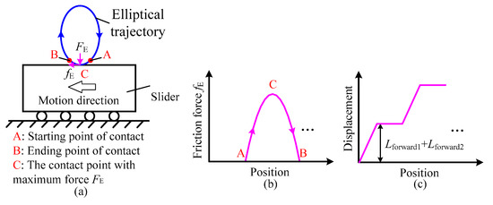
Figure 2.
Schematic diagram illustrating the suppressing principle by employing the elliptical trajectory: (a) the contact driving process, (b) the relationship between the position of output end of flexure hinge mechanism and the friction force, and (c) the stepping displacement.
The core of avoiding the backward motion by utilizing the elliptical trajectory is that the output end of the flexure hinge mechanism will periodically contact with the slider during the driving process, and the normal stick-slip driving mode is transformed into the elliptically intermittent driving mode. Figure 2a illustrates the contact driving process between the output end of flexure hinge mechanism and the slider. As the elliptical trajectory has an overlapping portion with one side of the slider, when the output end of the flexure hinge mechanism reaches the point A, it starts to contact the slider, thereby generating the normal force FE and friction force fE acting on the slider. When the friction force fE exceeds the friction force between the slider and the base, the flexure hinge mechanism will stick the slider to realize movement until it moves to the disengagement point B. This contact driving process is very similar to the “stick” stage in the normal stick-slip driving process described above. However, when analyzing the motion conditions during this process, it is worth nothing that the friction force fE is not always increasing, as during the “stick” stage in the normal stick-slip driving process. As illustrated in Figure 2b, the friction force fE will increase first and then decrease, and this process can be divided into two parts by point C (i.e., the point where the frictional force fE is the largest). From point A to point C, the output end of the flexure hinge mechanism draws closer to the slider, and thus the normal force FE and friction force fE increases. This part is almost the same as the “stick” stage in the normal stick-slip driving process, resulting in a forward displacement Lforward1. From point C to point B, the output end of the flexure hinge mechanism pulls away from the slider, and thus the normal force FE and friction force fE decrease. This part has the same role with the “slip” stage in the normal stick-slip driving process that makes the flexure hinge mechanism recover to its original status, but the big difference is the motion trajectory. For the normal stick-slip principle, the flexure hinge mechanism recovers by following the same trajectory of slow extension, resulting in the backward motion. However, as shown in Figure 2, when employing the elliptical trajectory, the flexure hinge mechanism recovers by following the other side of the elliptical trajectory, i.e., from point C to point B, which is the mirror image of that from point A to point C. Therefore, the backward motion appearing in the normal stick-slip principle will transform into a second forward displacement Lforward2. After that, the output end of flexure hinge mechanism moves from point B to point A, and prepares for the next driving cycle. Correspondingly, the one-step displacement is Lforward1 + Lforward2. Repeat the above driving processes, and the slider could realize the stepping displacement without backward motion in theory, as illustrated in Figure 2c.
To verify the feasibility of the elliptical trajectory on suppressing the backward motion, a prototype of piezoelectric actuator is designed. Figure 3a presents the three-dimensional (3D) structure of the actuator, which mainly consists of a flexure hinge mechanism, a slider, two piezoelectric stacks (PES1 and PES2), a translation stage, and a base. The translation stage is used for tuning the initial gap between the output end of the flexure hinge mechanism and the slider. The whole structure of the actuator, as well as the flexure hinge mechanism is designed symmetrically. The PES1 and PES2 (5 mm × 5 mm × 20 mm, AE0505D16DF, TOKIN, Japan) are preloaded and installed inside the flexure hinge mechanism, and they work as the driving source. The output displacements of PESs are transmitted and synthesized by the flexure hinge mechanism, whose detailed structure is presented in Figure 3b. To obtain a good elastic deformation performance, the flexure hinge mechanism is fabricated by aluminum alloy AL7075. To ensure the motion accuracy and reduce the stress concentration, the circular flexure hinges are employed as shown in Figure 3b. The core of the flexure hinge mechanism are two groups of dual right circular flexure hinge mechanism (DRCFH), which cause high stiffness and a compact structure. The symmetrical structure of the flexure hinge mechanism ensures that the bidirectional driving performances are consistent and the kinematics are simple. When two harmonic signals with a specific phase difference are applied to these two PESs, respectively, the resultant output displacement at the output end of the flexure hinge mechanism will follow an elliptical trajectory, which will be further discussed in Section 4.
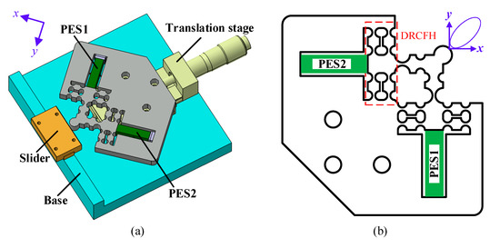
Figure 3.
(a) Three-dimensional (3D) structure of the designed piezoelectric actuator working by employing the elliptical trajectory, and (b) structure of the flexure hinge mechanism for generating the elliptical trajectory.
3. Theoretical Analysis of Flexure Hinge Mechanism
As the flexure hinge mechanism is responsible for the transmission and synthesis of the output displacement of the PESs, its compliance will directly determine the output characteristics of the actuator. Therefore, the compliance matrix method is employed to theoretically analyze the compliance of the flexure hinge mechanism, including the output compliance, input compliance and the magnification ratio of the DRCFH. Furthermore, by introducing the stiffness of the PES, the output range of the flexure hinge mechanism and the single-step displacement of the slider, with different initial gaps under a certain driving voltage and phase difference, were further deduced.
3.1. Compliance Analysis
3.1.1. Compliance Matrix Method
The compliance matrix method mainly includes two steps: (1) calculate the compliance matrix of each single flexure hinge and (2) combine them into a global compliance matrix according to the connection relationship of the flexure hinges after coordinate transformation.
Figure 4 shows the schematic diagram of the right circular flexure hinge, which is the main structure of the flexure hinge mechanism shown in Figure 3a. Koseki et al. summarized the compliance matrix of this kind of flexure hinges [36]. When the input force is acted on the point Oi, in the local coordinate system Oi-xyz, the output displacement can be obtained as
where Ci is the compliance matrix of a single right circular flexure hinge expressed in its local coordinate Oi-xyz when force Fi is acted on point Oi.
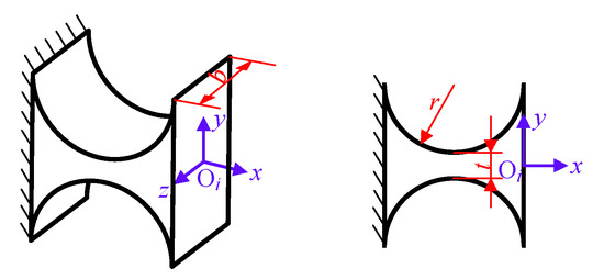
Figure 4.
Schematic diagram of the right circular flexure hinge.
No matter how complicated the flexure hinge mechanism is, it is always composed of finite number of basic hinges connected in series or in parallel. Yao et al. gave the rules of combining compliance matrix into a global compliance matrix and the coordinate transformation matrix for the series and parallel structures [37].
Figure 5 illustrates the series and parallel structures commonly used in the designed flexure hinge mechanism. As shown in Figure 5a, in a flexure hinge mechanisms in series, when the force FO2 is applied on the coordinate system O2-xyz and the output displacement δO1 is obtained in the coordinate system O1-xyz, the compliance CO1O2 of the series structure can be expressed as
where m is the number of the flexure hinges between the fixed end and the acting point of the force FO2; represents the transformation matrix of local coordinate Oi-xyz with respect to the coordinate Oj-xyz, and it can be given as
where is the rotation matrix which depends on the angle of the coordinate Oi-xyz with respect to the Oj-xyz, and is the translation matrix, which depends on the position vector of the coordinate Oi-xyz with respect to the Oj-xyz. When , can be derived as
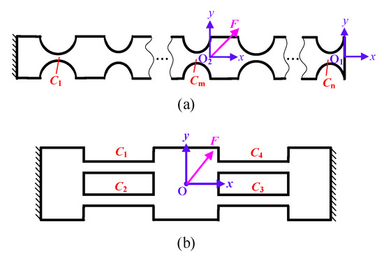
Figure 5.
Common serial and parallel flexure hinge mechanisms: (a) a series flexure hinge mechanism and (b) a typical parallel flexure hinge mechanism.
For a typical parallel structure as illustrated in Figure 5b, four leaf spring flexure hinges are connected with each other in a parallel form. When the force F is acted on the coordinate system O-xyz and the output displacement is obtained at the same position, the compliance COO of the parallel structure can be calculated by
where KOO is the stiffness matrix of the parallel structure.
3.1.2. Compliance of the DRCFH
The DRCFH structure is an important part of the flexure hinge mechanism of the designed actuator shown in Figure 3b. Figure 6a illustrates the separated DRCFH structure. It is similar to the typical parallel mechanism illustrated in Figure 5, and four flexible components consisting of two right circular flexure hinges in series are adopted to substitute for the leaf spring flexure hinges in Figure 5. Due to the symmetric structure of the DRCFH, only the compliance of the left half is calculated, and the right half can be obtained by rotating the left half with an angle of π around point A.

Figure 6.
(a) DRCFH structure and (b) left half of the DRCFH structure.
As shown in Figure 6b, the left half can be further divided into a lower part and an upper part, which are connected in parallel. According to Equations (2) and (5), the compliance of left half can be calculated as
where and denote the compliance of the lower and upper parts of the left half of the DRCFH, respectively. Ci (i = 1, 2, 3, 4) is the compliance of the right circular flexure hinge in the local coordinate system, which can be obtained according to Equation (1). TiA (i = 1, 2, 3, 4) is the transformation matrix from each local coordinate system Oi-xyz to the coordinate system A-xyz.
Then, the compliance of the right half of the DRCFH can be obtained by rotating the left half.
where TZ(π) represents the transformation matrix that contains only π degrees of rotation, and the rotation axis is z axis.
Finally, the compliance of the DRCFH can be deduced by connecting the left half and the right half in parallel according to Equation (5), and it is
3.1.3. Output Compliance
Figure 7a calibrates the flexure hinge mechanism by marking the nodes of every hinge. As illustrated in Figure 3b, the flexure hinge mechanism has a symmetrical structure, so it can be disassembled into three parts as shown in Figure 7b to simplify the calculation. Herein, the first part and the third part are both composed of the DRCFH and two flexure hinges connected in series, and the second part can be regarded as a rigid platform due to its high stiffness. Furthermore, the structure of the flexure hinges in the first part is symmetrical with that in the third part, which means the output performance of the third part can be obtained by the similar method. When an external force FA, coming from the PES, acts on the coordinate system A-xyz of the first part while no force acts at the third part, the output displacement δO in the coordinate system O-xyz can be obtained by calculating the output compliance COA according to the compliance matrix method aforementioned.
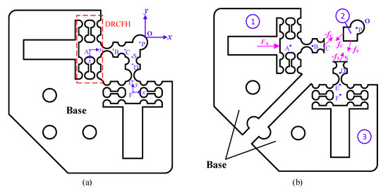
Figure 7.
(a) Coordinate calibration of the compliance mechanism, and (b) the divided flexure hinge mechanism and its force analysis.
As it is difficult to directly calculate the output compliance at point O due to some common mechanisms mentioned above, the displacement at point S and C is calculated first. As shown in Figure 7b, the displacement at point C of the first part is attributed to the combined action of external FA and internal force -fC, where fC is the interaction force between the first and the second part. Accordingly, the compliance of the first part being relevant to the two forces can be expressed as
where CCC is the compliance of the first part when the output displacement and force are both in the C-xyz coordinate system, and CCA represents the compliance between the output displacement in the coordinate system C-xyz and the force acting on the coordinate system A-xyz. Both of them can be calculated according to Equation (2).
Meanwhile, the force acting on the third part is only -fS, so the displacement at point S can be obtained easily as
As mentioned above, the second part can be regarded as a rigid body without elastic deformation, and this part is balanced with the action of fC and fS.
where is the deformation of transformation matrix, and its values are equal to .
As points S, C, and O are all on the same rigid body, the displacement relationship of the three points can be obtained by transformation, and thus
Substituting Equations (11), (12), and (14) into Equation (13), the internal forces fC and fS can be eliminated. Therefore, the following relationship could be obtained.
Hence, the output compliance COA can be given as
According to the principle of symmetry, the output compliance COF of the flexure hinge mechanism when piezoelectric force exerts in the vertical direction alone can be obtained as
As the piezoelectric stacks in two directions will work simultaneously during actual work, the output compliance of the entire flexure hinge mechanism needs to integrate COA and COF. Let the piezoelectric input force is FI = [fx, fy]T and the output displacement is δO = [δOx, δOy]T, then the output compliance COI can be expressed as
where COA(i,j) represents the element corresponding to the i-th row and j-th column of the compliance matrix COA. Due to the symmetry, COF(2,2) and COA(1,1) are equal, and COF(1,2) and COA(2,1) are also equal.
3.1.4. Input Compliance
The input compliance reflects the relationship between the input force of the flexure mechanism coming from the PES and the displacement at the input end. When the vertical piezoelectric stack works alone, the input displacement is affected by the compliance of the first part and the third part, as shown in Figure 7b. The compliance of the flexure hinges in these two parts can be divided into two groups connected in parallel. One group is composed of a horizontal series chain (the first part in Figure 7b) and flexure hinges D and E in series, and the other part is a DRCFH structure. Thus, when the vertical PES works individually, the input compliance can be deduced as
When the horizontal PES works individually, the input compliance CGG can be expressed as
Similarly, considering the two PESs work together, when the piezoelectric input force is FI = [fx, fy]T and the output displacement is δI = [δIx, δIy]T, the output compliance CII can be expressed as
In fact, CFF(1,2) and CGG(2,1) have a difference of about two orders of magnitude compared to CFF(2,2) and CGG(1,1), so the input compliance can be simplified to
Heretofore, the input and output compliances of the flexure hinge mechanism have been calculated. Based on these two parameters, the output range of the flexure hinge mechanism can be further determined.
3.2. Output Range
The output range of the flexure hinge mechanism determines the range of a single-step displacement of the actuator, which is one of the important output characteristics of the actuator. It can be deduced by multiplying the input range and the structure magnification ratio.
3.2.1. Magnification Ratio
From the above input and output compliances, the magnification ratio of the flexure hinge mechanism could be easily obtained. Taking the horizontal input as an example, let the input force equal FI, then the magnification ratio AO can be calculated as
3.2.2. Input Range
As the piezoelectric stack has a certain rigidity, and the deformation of the flexure hinge mechanism will apply a certain resistant force on the piezoelectric stack during operation, the elongation of the piezoelectric stack under the working state is less than that without a load. Let the elongation of the piezoelectric stack under the working condition equal L, and the elongation under no load is L0. Referring to the simplified method of the piezoelectric stack proposed by Li et al. [38], Figure 8 shows different states of the piezoelectric stack.
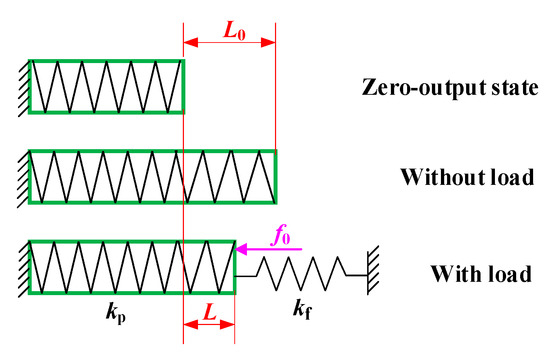
Figure 8.
Several states of piezoelectric stack [38].
As the piezoelectric stack and the flexure hinge mechanism can be regarded as a parallel system, the elongation L under the working state of the piezoelectric stack can be derived by
where kp is the stiffness of the piezoelectric stack; kf is the input stiffness of the flexure hinge mechanism which is equal to the inverse component of the compliance matrix of the flexure hinge mechanism along the piezoelectric input direction, i.e., kf = CII −1(1,1); and f0 is the preload during installation.
When neglecting the hysteresis and nonlinearity of the piezoelectric stack, referring to the model of Tian et al. [39], the relationship between the excitation voltage VPES of the piezoelectric stack and its elongation L0 without load can be expressed as
where n is the number of the layers of the piezoelectric ceramic in the PES, d33 is the piezoelectric constant, and k is the equivalent proportional coefficient.
3.2.3. Output Range
After the magnification ratio and output range are deduced, the output range R of the flexure hinge mechanism along any direction of x and y is
3.3. Single-Step Displacement of the Slider
The output range of the flexure hinge mechanism is not the final single-step displacement of the slider, whereas it indirectly affects the output displacement of the slider by affecting the size of the elliptical driving trajectory. Figure 9 exaggeratedly describes the relationship between the output trajectory of the flexure hinge mechanism and the single-step displacement of the slider, and the output trajectory is partitioned into two areas by the line where the minor axis lies; s and l represent the single-step displacement and gap between the slider and the flexure hinge, respectively. When the contact face of the flexure hinge mechanism and the slider is in Area Ι, there will be no backward motion appearing in the output displacement of the slider. On the the contrary, when the contact face is in Area ΙΙ, backward motion will appear in the output displacement of the slider due to the properties of elliptical trajectory. Therefore, the initial gap should be larger than lmin, as shown in Figure 9.
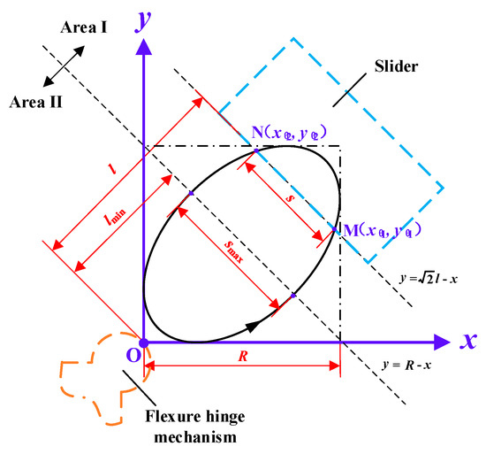
Figure 9.
Relationship between the output range of the flexure hinge mechanism and the single-step displacement of the slider.
It is well known that the phase difference of the output displacement along the x and y axis have an effect on the elliptical trajectory. When the phase of the output displacement along the x axis is θ (θ∈(0, 2π)), and the phase difference is φ (φ∈(0, π/2)), the movements of the composite elliptical trajectory along the x axis and the y axis can be derived as
As shown in Figure 9, when the initial gap between the slider and the flexure hinge mechanism is l, the contact starting point of the slider and the flexure hinge is point M (xθ1, yθ1), the end point is point N (xθ2, yθ2), and the corresponding single-step displacement of the slider is s. The analytical expression of line MN is . By substituting Equations (29) and (30) into the analytical expression of line MN, the following equation can be obtained:
Let θ1 and θ2 be the two solutions of Equation (31), which represent the two values of θ when the flexure hinge mechanism and the slider are at points M and N, respectively. The analytical expression of the minimum value of the initial gap is , and the maximum value lmax can be obtained by equalizing Equations (29) and (30); it can be deduced as .
Then, the single-step displacement of the slider can be represented by the coordinates of the points M and N.
Observing Equation (32), the maximum single-step displacement of the slider can be easily obtained.
According to Equations (28) and (33), it is easily noted that the maximum single-step displacement smax of the slider has a linear function relationship with the driving voltage, and a trigonometric function relationship with the phase difference.
Then, by combining Equations (31)–(33) the single-step displacement of the slider can be derived as
In Equation (34) is not easy to visualize the relationship between all the variables. As the phase difference is often set as a constant in the experiment, the relationship curves between the single-step displacement of the slider s and the initial gap (step is (lmax−lmin)/100) are drawn under different voltages and a constant phase difference of 45°, as shown in Figure 10.
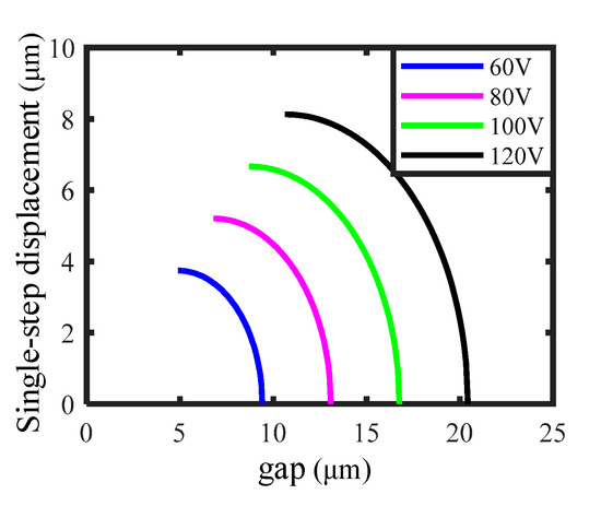
Figure 10.
Curves between the single-step displacement of the slider and the gap obtained under different voltages and a constant phase difference of 45°.
From Figure 10, several characteristics can be observed. First of all, for each curve, as the gap increases, the single-step displacement of the slider shows a descending trend, and the descending speed becomes faster and faster. When the gap reaches a certain value, the single-step displacement of the slider is zero. Secondly, for the same gap, the single-step displacement of the slider increases as the voltage rises. Thirdly, as the voltage rises, the minimum gap, the maximum gap, and the gap adjustment interval are all promoted, which is consistent with the intuitive cognition.
4. Generation of Elliptical Trajectory
To realize the principle as illustrated in Figure 2, the generation of an elliptical trajectory is the critical step. In this paper, the flexure hinge mechanism combined with two PESs is used for this purpose. As the output axes of two PESs are perpendicular to each other as illustrated in Figure 3b. According to the elliptical equation, if two harmonic signals with the same amplitude and frequency, but a specific phase difference, are applied to these two PESs, respectively, the output end of the flexure hinge mechanism will in theory generate an elliptical trajectory. In Figure 11, an example is given. When two sine-wave driving voltages with a phase difference of 45° and the amplitude of 80 V, as plotted in Figure 11a, are applied to two PESs, respectively, the output range R of the compliance mechanism can be calculated first. Then, according to Equations (29) and (30), the motion trajectory at the output end O is synthesized, which shows elliptical features with the major axis and the minor axis being perpendicular and parallel to the axis of slider, respectively, as illustrated in Figure 11b. Furthermore, if the amplitude and frequency of the two driving voltages are fixed, the shape of the elliptical trajectory (the lengths of major axis and minor axis) will be determined by the phase difference. According to the theoretical derivation in the part 3, the theoretical motion elliptical trajectories of both output point O and point P can be expediently deduced. For comparison with the following experiment results, the theoretical elliptical trajectories at point P corresponding to the phase differences of 0°, 15°, 30°, 45°, 60°, and 75°are preferred in Figure 12a–f, respectively. As the phase difference increases from 0° to 75°, the length of major axis gradually decreases, and the length of minor axis increases.
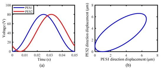
Figure 11.
An example showing the generation of elliptical trajectory: (a) two sine-wave driving voltages with the same amplitude and frequency but a phase difference of 45°, and (b) the resultant elliptical trajectory.
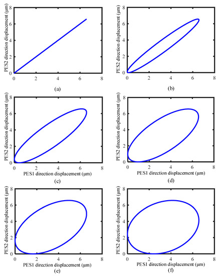
Figure 12.
Theoretical motion trajectories of point P corresponding to different phase differences: (a) 0°, (b) 15°, (c) 30°, (d) 45°, (e) 60°, and (f) 75°.
To obtain the real motion trajectory of the output end of the flexure hinge mechanism, an experimental system, as shown in Figure 13a, was established. It mainly includes the prototype of piezoelectric actuator, the voltage amplifier (E01.A3, Harbin Core Tomorrow Science and Technology Co., Ltd., Harbin, China), the industrial control computer, two laser displacement sensors (LK-H020, Keyence Corporation, Osaka, Japan), and the vibration isolation platform. The driving voltage waves were programmed by the LabVIEW software, and sent to the analog output card (PCI NI6722, National Instruments Corporation, Austin, TX, USA). The generated driving signals were further amplified by the voltage amplifier, and then applied to these two PESs. The resultant displacements at the output end of the flexure hinge mechanism along the major and minor axes of elliptical trajectories were measured synchronously by two laser displacement sensors, respectively, as illustrated in Figure 13b,c. A test block pasted with the silicon wafer is placed at point P to reflect the laser beam from the laser sensor, in turn, to realize the measurement of displacement, as shown in Figure 13c.
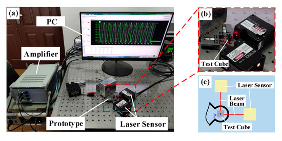
Figure 13.
Experimental system for testing the motion trajectory of the output end of the flexure hinge mechanism: (a) overall experimental devices, (b) the local detailed graph of the actuator and the laser sensors, and (c) the test schematic diagram.
Using the above experimental system, to test the elliptical trajectory, two sine-wave driving voltages with the amplitude of 80 V, frequency of 20 Hz and various phase differences (0°, 15°, 30°, 45°, 60°, and 75°) were applied to these two PESs. For comparison, the measured displacements (along the major and minor axes of elliptical trajectories) were converted into the displacements along the PES1 direction and the PES2 direction, which are the same as the coordinate system of the theoretical calculation above. Then, the measured motion trajectories after transformation and the theoretical motion trajectories are simultaneously presented in Figure 14.
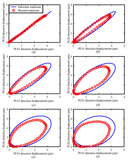
Figure 14.
Comparison of the measured and theoretical motion trajectories of the output end of the flexure hinge mechanism under different phase differences: (a) 0°, (b) 15°, (c) 30°, (d) 45°, (e) 60°, and (f) 75°.
In Figure 14, the measured motion trajectories under various phase differences show similar features to those obtained by the theoretical analysis. When the phase difference is 0°, the resultant motion is an approximate straight line; when increasing the phase difference, the real motion trajectory shows features of elliptical trajectory, and the length of major axis first increases and then decreases. However, some differences still exist when compared with the theoretical elliptical trajectories. The measured length of major axis is less than that predicted by theoretical analysis. Corresponding to the driving voltage of 80 V, the theoretical displacement of PESs is 6.57 μm, however, the measured displacement at the output end is about 6 μm. Thus, the length of the major axis is shortened. From the perspective of theoretical calculation, the preload f0 during installation in Equation (28) is unmeasurable, which may be the main reason for the great difference. Furthermore, with consideration of the limitations of the experimental device, it may also be caused by the inevitable offset between the actual measurement position and the theoretical circle center, caused by the volume of the test cube that cannot be ignored. Another difference is that the measured motion trajectories show some distortion, which could be the result of coupled motion existing between two output axes of PESs. In other words, when PES1 outputs displacement, it will also lead to displacement output along the axis of PES2. This kind of coupled motion would intrinsically exist if the elliptical trajectory were generated by two vertically arranged PESs and a symmetrical flexure hinge mechanism.
Although the real motion trajectories are a little different from the theoretical trajectories, the approximate elliptical trajectories have been achieved under some phase differences, for example, 15°, 30°, 45°, and 60°. As the emphasis of this study is on suppressing the backward motion which appears in the normal stick-slip principle by employing the elliptical trajectory, the coupled motion between two axes of PESs will not be discussed in detail here, and in the future, a specific flexure hinge mechanism will be further developed to reduce the coupled phenomenon.
Next, a suitable phase difference will be selected for the following experiments, and the selection criteria is related with the lengths of the major axis and minor axis of the elliptical trajectory. If the major axis is too short, the gap adjustment interval (GDI) will be shortened, increasing the difficulty in position adjustment. If the minor axis is too short, the maximum single-step displacement (MSD) of the slider will decrease, which weakens the driving ability.
The relationship between the MSD and the phase difference has been established in Equation (33). Here, the GDI should also be quantified. The value range of the gap l has been given above, so let the GDI be lint, which can be expressed as
When only considering the influence of the phase difference and fixing the voltage to 80 V, the relationship between the MSD (GDI) and the phase difference changing from 0 to π/2 (step value π/36) can be obtained, as illustrated in Figure 15.
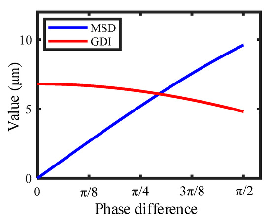
Figure 15.
The maximum single-step displacement (MSD) and the gap adjustment interval (GDI) changing with the phase difference in the range of 0 to π/2 (step value π/36).
Figure 15 indicates that the trends of MSD and GDI are opponent, which means that larger MSD and GDI cannot be obtained at the same time. The most compromised phase difference calculated is 0.295π, which is the intersection of the two curves and, at this point, MSD and GDI are equal, and both have larger values. In practical applications, it is necessary to select an appropriate phase difference according to the performance requirements of the actuators; that is, when a larger MSD is required to pursue larger driving velocity, the phase difference exceeding 0.295π may be a better choice, and in order to meet the intention of convenient adjustment, less than 0.295π may be more suitable. This paper is mainly to prove the feasibility of the driving principle, so in the follow-up experiments, π/4 is selected as the representative to verify the driving performances for convenience
5. Verification and Performances
In order to verify the feasibility of the proposed driving principle, and also to test the output performances of the designed piezoelectric actuator, an experimental system, as shown in Figure 16, was established. Being different from the experimental system in Figure 13, this system only requires one laser displacement sensor to measure the output displacement of the slider.
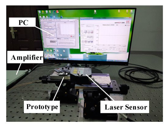
Figure 16.
Experimental system for testing the output performances of the designed piezoelectric actuator.
According to the suppressing principle, to suppress the backward motion, the relative gap between the output end of flexure hinge mechanism and the slider must be within a certain range. If the relative gap is too big, as the major axis of motion trajectory has limited length, the output end of flexure hinge mechanism is not able to contact the slider, or the effective driving length is too short. If it is too small, the output end of flexure hinge mechanism would not completely separate from the slider when it moves from point B to point A, as illustrated in Figure 2, resulting in the backward motion. Therefore, a suitable relative gap should be determined first by experiments.
Here, to find the suitable relative gap, two sine-wave driving voltages with the amplitude of 80 V, frequency of 20 Hz and phase difference of 45° (the driving voltage of PES1 is ahead 45° of that of PES2) were applied to these two PESs. Initially, we made the flexure hinge mechanism have contact with the slider. In this case, the backward motion will appear in the output displacement. Afterwards, we gradually increased the relative gap until the backward motion almost disappeared, and the corresponding gap was defined as the critical relative gap, i.e., the relative gap of zero. When further increasing the relative gap to +5 μm, the slider did not move due to the large gap; whereas, when decreasing the relative gap to −5 μm, the backward motion will appear again. The corresponding experimental results are presented in Figure 17. Here, the forward motion is defined as the motion of the slider to the side of PES1, and when the slider moves to the side of PES2, it is regarded as the reverse motion. Accordingly, the subsequent experiments were carried out under this critical relative gap of zero.
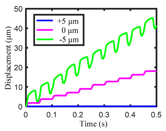
Figure 17.
Motion characteristics of the slider under various gaps.
Under this critical relative gap and the driving frequency of 20 Hz, the output displacement of the slider changing with various driving voltages (60, 80, 100, and 120 V) was measured and presented in Figure 18a. It is rather remarkable that the slider almost does not move when the driving voltage is 60 V. This is as the critical relative gap is identified for the driving voltage of 80 V, which may be a little large for 60 V. Thus, the output end of flexure hinge mechanism cannot contact the slider. When increasing the driving voltage to 80, 100, and 120 V, very good stepping motions, almost without backward motion, are achieved, which means that the critical relative gap is also applicable for these driving voltages.
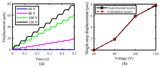
Figure 18.
(a) Motion characteristics of the slider obtained under the critical relative gap and various driving voltages, and (b) single-step displacement changing with the voltage under the critical relative gap.
Figure 18b shows the relationship between the voltage and the single-step displacement of the slider under the critical relative gap. The experimental results are presented by the solid line, and the theoretical calculation results are presented by the dashed line. These two results are very close, and the maximum deviation is only 2.67%, demonstrating the correctness of the theoretical analysis. However, it is noted that, no matter which curve it is, it shows strong nonlinearity. If the gap is changed, the curve will also change drastically. It is impossible to calculate the equation of the curve with a simple function.
Although the actuator shown in Figure 3 is designed for working under the elliptical trajectory, it can realize normal stick-slip driving when a trapezoid driving voltage is applied to the PES1 or PES2. Accordingly, for comparison, under the critical relative gap, the trapezoid driving voltage with a frequency of 20 Hz and various amplitudes (40, 60, 80, 100, and 120 V) were applied to PES2. Figure 19 presents the output displacement. The change in the amplitude of driving voltage here is used to simulate the effects of a relative gap on the output characteristics. Evidently, although the backward motion is reduced when decreasing the driving voltage, it indeed exists for all the driving voltages from 40 to 120 V. The comparative results in Figure 18a and Figure 19 demonstrate the effectiveness of the elliptical trajectory on suppressing the backward motion.
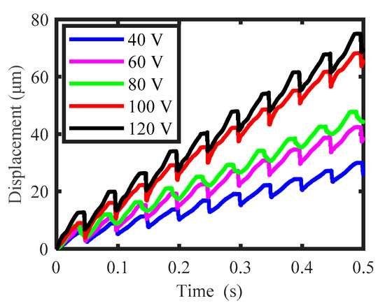
Figure 19.
Output displacement of the slider working under the normal stick-slip driving principle.
Furthermore, under the driving voltages of 80 V, phase difference of 45°, and critical relative gap, the effects of driving frequency on the output characteristics are tested. Figure 20a shows the output displacement of the slider obtained under various driving frequencies (20, 40, 60, 80, and 100 Hz). Figure 20b shows the relationship between the velocity of the slider and the frequency. It is easily observed that increasing the driving frequency, the motion velocity of the slider increases linearly, reaching 366 μm/s at 100 Hz. Therefore, the velocity of the slider could be easily controlled by only changing the frequency. Furthermore, when the driving frequency is in the range of 20 to 60 Hz, an ideal stepping displacement without the backward motion is achieved. Further, increasing the driving frequency to 80 and 100 Hz, a very small backward motion appears. This kind of change is mainly due to the effects of driving frequency on the output characteristics of PES, which further affects the contact condition between the output end of flexure hinge mechanism and the slider. However, compared with the results obtained under the normal stick-slip driving principle in previous studies [24,25,31,32], the backward motion in Figure 20a is quite small, especially as the ideal stepping displacement without backward motion could obtained under the frequency range of 20 to 60 Hz.
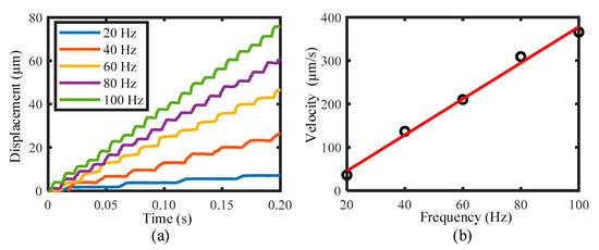
Figure 20.
(a) Motion characteristics of the slider obtained under various driving frequencies, and (b) the velocity of the slider changing with the frequency under the critical relative gap.
The above results show the forward motion characteristics of the slider. As the designed actuator has a symmetrical structure, the reverse motion could be realized by simply changing the phase difference of the driving voltages, i.e., the driving voltage of PES2 being ahead 45° of that of PES1. Under the driving voltage of 80 V, frequency of 20 Hz, and critical relative gap, reverse motion of the slider was attempted, and the output displacement is presented in Figure 21. It is noteworthy that the reverse motion of the slider also shows the stepping characteristics almost without the backward motion. Thus, forward and reverse stepping motions of the slider have been successfully realized by employing the elliptical trajectory, and the backward motion appearing in the normal stick-slip principle has been effectively suppressed, verifying the feasibility and validity of the suppressing principle by employing the elliptical trajectory.
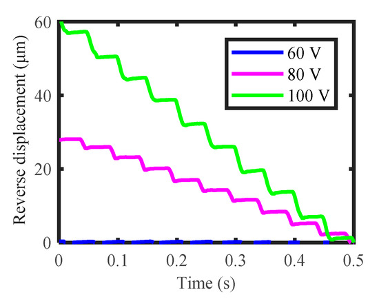
Figure 21.
Reverse motion characteristics of the slider under the driving frequency of 20 Hz, various driving voltages, and critical relative gap.
6. Conclusions
In this paper, to avoid the inherent backward motion of stick-slip piezoelectric actuators, a novel principle of utilizing the elliptical trajectory was proposed. According to this principle, an actuator prototype was designed by using a flexure hinge mechanism and two vertically arranged piezoelectric stacks. By analysis and experiments, the following conclusions could be obtained.
- Although the measured motion trajectories were a little different from the theoretical ones, the approximate elliptical trajectories had been achieved by the flexure hinge mechanism combined with two vertically arranged piezoelectric stacks;
- There existed a critical relative gap, under which the piezoelectric actuator could output stepping displacement with completely suppressed backward motion when working under the elliptical trajectory. However, under this gap, the backward motion appeared to correspond to various driving voltages when the actuator worked under the normal stick-slip driving principle. These comparative results demonstrated the feasibility and effectiveness of the proposed suppressing principle;
- Under this critical relative gap, when changing the driving voltage and frequency in a certain range, the actuator could achieve forward and reverse stepping displacement nearly without the backward motion when working under the elliptical trajectory, further confirming the applicability.
Author Contributions
Conceptualization, H.H.; methodology, X.Y.; validation, X.Y., J.T. and W.G.; investigation, J.T. and H.F.; resources, H.H.; writing—original draft preparation, X.Y. and J.T.; writing—review and editing, H.H.; visualization, J.L. and T.L.; supervision, H.H.; project administration, H.H.; and funding acquisition, H.H. All authors have read and agreed to the published version of the manuscript.
Funding
This research was funded by the National Natural Science Foundation of China (Grant No. 52075221), the Young Elite Scientists Sponsorship Program by CAST (YESS) (Grant No. 2017QNRC001), the Graduate Innovation Fund of Jilin University (Grant No. 101832020CX100), and the Fundamental Research Funds for the Central Universities (2019–2021).
Conflicts of Interest
The authors declare no conflict of interest.
References
- Cai, K.; He, X.; Tian, Y.; Liu, X.; Zhang, D.; Shirinzadeh, B. Design of a XYZ Scanner for Home-Made High-Speed Atomic Force Microscopy. Microsyst. Technol. 2017, 24, 3123–3132. [Google Scholar] [CrossRef] [Green Version]
- Yong, Y.K.; Wadikhaye, S.P.; Fleming, A.J. High Speed Single- and Dual-Stage Vertical Positioners. Rev. Entific. Instrum. 2016, 87, 085101. [Google Scholar] [CrossRef] [PubMed]
- Zhu, Z.; To, S.; Zhu, W.; Li, Y.; Huang, P. Optimum Design of a Piezo-Actuated Tri-Axial Compliant Mechanism for Nano-Cutting. IEEE Trans. Ind. Electron. 2017, 65, 6362–6371. [Google Scholar] [CrossRef]
- Zhu, W.-L.; Zhu, Z.; He, Y. Development of a Novel 2-D Vibration-Assisted Compliant Cutting System for Surface Texturing. IEEE/ASME Trans. Mechatron. 2017, 22, 1796–1806. [Google Scholar] [CrossRef]
- Hu, H.; Zhao, H.; Jie, M. A Novel and Compact Nanoindentation Device for in Situ Nanoindentation Tests inside the Scanning Electron Microscope. AIP Adv. 2012, 1, 012104. [Google Scholar] [CrossRef] [Green Version]
- Rabe, R.; Breguet, J.M.; Schwaller, P.; Stauss, S.; Michler, J. Observation of Fracture and Plastic Deformation during Indentation and Scratching inside the Scanning Electron Microscope. Thin Solid Film. 2004, 469, 206–213. [Google Scholar] [CrossRef]
- Huang, H.; Zhao, H. In Situ Nanoindentation and Scratch Testing Inside Scanning Electron Microscopes: Opportunities and Challenges. Sci. Adv. Mater. 2014, 6, 875–889. [Google Scholar] [CrossRef]
- Ha, N.S.; Nguyen, Q.V.; Goo, N.S.; Park, H.C. Static and Dynamic Characteristics of an Artificial Wing Mimicking an Allomyrina Dichotoma Beetle’s Hind Wing for Flapping-Wing Micro Air Vehicles. Exp. Mech. 2012, 52, 1535–1549. [Google Scholar] [CrossRef]
- Ha, N.S.; Jin, T.L.; Goo, N.S.; Park, H.C. Anisotropy and Non-Homogeneity of an Allomyrina Dichotoma Beetle Hind Wing Membrane. Bioinspiration Biomim. 2011, 6, 046003. [Google Scholar] [CrossRef]
- Liang, C.; Wang, F.; Shi, B.; Huo, Z.; Zhou, K.; Tian, Y.; Zhang, D. Design and Control of a Novel Asymmetrical Piezoelectric Actuated Microgripper for Micromanipulation. Sens. Actuators A Phys. 2017, 269, 227–237. [Google Scholar] [CrossRef]
- Wang, F.; Liang, C.; Tian, Y.; Zhao, X.; Zhang, D. Design and Control of a Compliant Microgripper With a Large Amplification Ratio for High-Speed Micro Manipulation. IEEE/ASME Trans. Mechatron. 2016, 21, 1262–1271. [Google Scholar] [CrossRef]
- Xuan, Z.; Jin, T.; Ha, N.S.; Goo, N.S.; Kim, T.H.; Bae, B.W.; Ko, H.S.; Yoon, K.W. Performance of Piezo-Stacks for a Piezoelectric Hybrid Actuator by Experiments. J. Intell. Mater. Syst. Struct. 2014, 25, 2212–2220. [Google Scholar] [CrossRef]
- Ha, N.S.; Le, V.T.; Goo, N.S. Investigation of Fracture Properties of a Piezoelectric Stack Actuator Using the Digital Image Correlation Technique. Int. J. Fatigue 2017, 101, 106–111. [Google Scholar] [CrossRef]
- Michler, J.; Rabe, R.; Bucaille, J.L.; Moser, B.; Breguet, J.M. Investigation of Wear Mechanisms through in Situ Observation during Microscratching inside the Scanning Electron Microscope. Wear 2005, 259, 18–26. [Google Scholar] [CrossRef]
- Meza, L.R.; Das, S.; Greer, J.R. Strong, Lightweight, and Recoverable Three-Dimensional Ceramic Nanolattices. Science 2014, 345, 1322–1326. [Google Scholar] [CrossRef] [PubMed] [Green Version]
- Huang, H.; Zhao, H.; Shi, C.; Wu, B.; Fan, Z.; Wan, S.; Geng, C. Effect of residual chips on the material removal process of the bulk metallic glass studied by in situ scratch testing inside the scanning electron microscope. AIP Adv. 2012, 2, 042193. [Google Scholar] [CrossRef]
- Li, J.; Huang, H.; Morita, T. Stepping Piezoelectric Actuators with Large Working Stroke for Nano-Positioning Systems: A Review. Sens. Actuators A Phys. 2019, 292, 39–51. [Google Scholar] [CrossRef]
- Wang, S.; Rong, W.; Wang, L.; Xie, H.; Sun, L.; Mills, J.K. A Survey of Piezoelectric Actuators with Long Working Stroke in Recent Years: Classifications, Principles, Connections and Distinctions. Mech. Syst. Signal Process. 2019, 123, 591–605. [Google Scholar] [CrossRef]
- Wang, L.; Chen, W.; Liu, J.; Deng, J.; Liu, Y. A Review of Recent Studies on Non-Resonant Piezoelectric Actuators. Mech. Syst. Signal Process. 2019, 133, 106254. [Google Scholar] [CrossRef]
- Zhang, S.; Liu, J.; Deng, J.; Liu, Y. Development of a Novel Two-DOF Pointing Mechanism Using a Bending-Bending Hybrid Piezoelectric Actuator. IEEE Trans. Ind. Electron. 2018, 66, 7861–7872. [Google Scholar] [CrossRef]
- Liu, Y.; Yan, J.; Wang, L.; Chen, W. A Two-DOF Ultrasonic Motor Using a Longitudinal–Bending Hybrid Sandwich Transducer. IEEE Trans. Ind. Electron. 2018, 66, 3041–3050. [Google Scholar] [CrossRef]
- Li, J.; Zhao, H.; Qu, H.; Cui, T.; Fan, Z. A Piezoelectric-Driven Rotary Actuator by Means of Inchworm Motion. Sens. Actuators A Phys. 2013, 194, 269–276. [Google Scholar] [CrossRef]
- Wang, S.; Rong, W.; Wang, L.; Pei, Z.; Sun, L. A Novel Inchworm Type Piezoelectric Rotary Actuator with Large Output Torque: Design, Analysis and Experimental Performance. Precis. Eng. 2017, 51, 545–551. [Google Scholar] [CrossRef]
- Wang, S.; Rong, W.; Wang, L.; Pei, Z.; Sun, L. Design, Analysis and Experimental Performance of a Novel Stick-Slip Type Piezoelectric Rotary Actuator Based on Variable Force Couple Driving. Smart Mater. Struct. 2017, 26, 055005. [Google Scholar] [CrossRef]
- Zhang, Y.; Peng, Y.; Sun, Z.; Yu, H. A Novel Stick-Slip Piezoelectric Actuator Based on a Triangular Compliant Driving Mechanism. IEEE Trans. Ind. Electron. 2018, 66, 5374–5382. [Google Scholar] [CrossRef]
- Fan, H.; Tang, J.; Li, T.; Yang, X.; Huang, H. Active Suppression of the Backward Motion in a Parasitic Motion Principle (PMP) Piezoelectric Actuator. Smart Mater. Struct. 2019, 28, 125006. [Google Scholar] [CrossRef]
- Tang, J.; Fan, H.; Liu, J.; Huang, H. Suppressing the Backward Motion of a Stick–Slip Piezoelectric Actuator by Means of the Sequential Control Method (SCM). Mech. Syst. Signal. Process. 2020, 143, 106855. [Google Scholar] [CrossRef]
- Huang, H. A Novel Driving Principle by Means of the Parasitic Motion of the Microgripper and Its Preliminary Application in the Design of the Linear Actuator. Rev. Sci. Instrum. 2012, 83, 055002. [Google Scholar] [CrossRef] [PubMed]
- Huang, H.; Fu, L.; Zhao, H.; Shi, C.; Ren, L.; Li, J.; Qu, H. Note: A Novel Rotary Actuator Driven by Only One Piezoelectric Actuator. Rev. Sci. Instrum. 2013, 84, 121101. [Google Scholar] [CrossRef]
- Cheng, T.; He, M.; Li, H. A Novel Trapezoid-Type Stick–Slip Piezoelectric Linear Actuator Using Right Circular Flexure Hinge Mechanism. IEEE Trans. Ind. Electron. 2017, 64, 5545–5552. [Google Scholar] [CrossRef]
- Guo, Z.; Tian, Y.; Zhang, D.; Wang, T.; Wu, M. A Novel Stick-Slip Based Linear Actuator Using Bi-Directional Motion of Micropositioner. Mech. Syst. Signal. Process. 2019, 128, 37–49. [Google Scholar] [CrossRef] [Green Version]
- Li, Y.; Li, H.; Cheng, T.; Lu, X.; Zhao, H.; Chen, P. Note: Lever-Type Bidirectional Stick-Slip Piezoelectric Actuator with Flexible Hinge. Rev. Sci. Instrum. 2018, 89, 086101. [Google Scholar] [CrossRef]
- Huang, H.; Li, J.; Zhao, H.; Shi, C. On the Correlation between the Structure and One Stepping Characteristic of a Piezo-Driven Rotary Actuator. Microsyst. Technol. 2016, 22, 2821–2827. [Google Scholar] [CrossRef]
- Li, J.; Zhou, X.; Zhao, H.; Shao, M.; Li, N.; Zhang, S.; Du, Y. Development of a Novel Parasitic-Type Piezoelectric Actuator. IEEE/ASME Trans. Mechatron. 2017, 2, 22–29. [Google Scholar] [CrossRef]
- Wen, J.; Wan, N.; Wang, R.; Chen, S.; Zheng, J.; Li, J. A Novel Linear Walking Type Piezoelectric Actuator Based on the Parasitic Motion of Flexure Mechanisms. IEEE Access 2019, 7, 25908–25914. [Google Scholar] [CrossRef]
- Koseki, Y.; Tanikawa, T.; Koyachi, N.; Arai, T. Kinematic analysis of a translational 3-d.o.f. micro-parallel mechanism using the matrix method. Adv. Robot. 2002, 16, 251–264. [Google Scholar] [CrossRef]
- Jiang, Y.; Li, T.M.; Wang, L.P. Stiffness Modeling of Compliant Parallel Mechanisms and Applications in the Performance Analysis of a Decoupled Parallel Compliant Stage. Rev. Sci. Instrum. 2015, 86, 131–792. [Google Scholar] [CrossRef] [PubMed]
- Li, Y.; Huang, J.; Tang, H. A Compliant Parallel XY Micromotion Stage with Complete Kinematic Decoupling. IEEE Trans. Autom. Sci. Eng. 2012, 9, 538–553. [Google Scholar] [CrossRef]
- Tian, Y.; Zhang, D.; Shirinzadeh, B. Dynamic Modelling of a Flexure-Based Mechanism for Ultra-Precision Grinding Operation. Precis. Eng. 2011, 35, 554–565. [Google Scholar] [CrossRef]
Publisher’s Note: MDPI stays neutral with regard to jurisdictional claims in published maps and institutional affiliations. |
© 2021 by the authors. Licensee MDPI, Basel, Switzerland. This article is an open access article distributed under the terms and conditions of the Creative Commons Attribution (CC BY) license (https://creativecommons.org/licenses/by/4.0/).