Article

Effects of Ferroelectric Fillers on Composite Dielectric Elastomer Actuator

1
Department of Aerospace Engineering, Embry-Riddle Aeronautical University, Daytona Beach, FL 32114, USA
2
Department of Mechanical Engineering, Embry-Riddle Aeronautical University, Daytona Beach, FL 32114, USA
*
Author to whom correspondence should be addressed.
Actuators 2021, 10(7), 137; https://doi.org/10.3390/act10070137
Submission received: 14 May 2021 / Revised: 8 June 2021 / Accepted: 17 June 2021 / Published: 22 June 2021
(This article belongs to the Special Issue Electroactive Polymer Actuators)

Abstract

:
Integrating nano- to micro-sized dielectric fillers to elastomer matrices to form dielectric composites is one of the commonly utilized methods to improve the performance of dielectric elastomer actuators (DEAs). Barium titanate (BaTiO3) is among the widely used ferroelectric fillers for this purpose; however, calcium copper titanate CaCu3Ti4O12 (CCTO) has the potential to outperform such conventional fillers. Despite their promising performance, CCTO-based dielectric composites for DEA application are studied to a relatively lower degree. Particularly, the composites are characterized for a comparably small particle loading range, while critical DEA properties such as breakdown strength and nonlinear elasticity are barely addressed in the literature. Thus, in this study, CCTO was paired with polydimethylsiloxane (CH3)3SiO[Si(CH3)2O]nSi(CH3)3 (PDMS), Sylgard 184, to gain a comprehensive understanding of the effects of particle loading and size on the dielectric composite properties important for DEA applications. The dielectric composites’ performance was described through the figures of merit (FOMs) that consider materials’ Young’s modulus, dielectric permittivity, and breakdown strength. The optimum amounts of the ferroelectric filler were determined through the FOMs to maximize composite DEA performance. Lastly, electromechanical testing of the pre-stretched CCTO-composite DEA validated the improved performance over the plain elastomer DEA, with deviations from prediction attributed to the studied composites’ nonlinearity.

1. Introduction

Owing to their outstanding electromechanical characteristics, dielectric elastomer actuators (DEAs) have become one of the most intensively studied and developed electroactive polymers (EAP) [1]. A common DEA can be described as a parallel plate capacitor with compliant electrodes and a soft dielectric elastomer in between. When voltage is applied to the electrodes, the pressure generated by electrostatic attraction compresses the elastomer through the out-of-plane direction and expands the entire actuator in the in-plane direction. To estimate the performance of DEA, a commonly accepted figure of merit (FOM) is used [2],
F O M = 3 ε r ε 0 E B 2 Y
where ε r , ε 0 , E B , and Y are the dielectric elastomer’s relative permittivity, vacuum permittivity, breakdown strength, and Young’s modulus, respectively. The FOM assumes the elastomer to be linearly elastic with dielectric properties independent of strain to ease DEA performance estimation.
As per Equation (1), the FOM entirely depends on DEA elastomer material properties, with acrylic and silicone elastomers being the most widely used to achieve high actuation performance. While acrylic DEAs usually provide larger actuation deformation due to higher relative permittivity and softness, silicone DEAs possess more stable time- and temperature-dependent properties, longer lifetime, and often higher specific energy density. These properties make silicone a more suitable elastomer material for practical implementation and prospective DEA commercialization [3]. Although currently available commercial silicones can produce DEAs with reliable and consistent characteristics, industrial implementation requires elastomers that produce higher actuation forces and deformations. Thus, several methods, such as adding highly dielectric [4,5] and conductive fillers [6], blending elastomers with polymers [7], as well as chemically modifying elastomers [8,9] are used to improve silicones’ dielectric and mechanical properties. Although an increase in permittivity can be attained using these methods, other material properties, namely higher Young’s modulus and lower breakdown strength, can unfavorably affect the actuation performance. Nevertheless, in dielectric composites, these negative drawbacks can be mitigated through an optimized amount of evenly dispersed particles.
Among traditionally utilized fillers, titanium-based ferroelectric particles have demonstrated the ability to increase elastomer’s permittivity [3]. Barium titanate (BaTiO3) is a particularly successful and commonly employed filler in dielectric composites due to its high relative permittivity, averaging around 6000 [10,11]. However, calcium copper titanate CaCu3Ti4O12 (CCTO) recently received exceptional attention attributed to its immense dielectric permittivity, which varies between 10,000 and 100,000 for pure materials and as high as 400,000 with chemically doped modifications [12]. Unlike BaTiO3, CCTO-based composites are relatively unexplored for DEA application. Some studies investigated the effects of filler loading on polymer composites by using single sized CCTO particles [13,14,15,16,17,18,19], while others investigated the effect of particle size by using fixed weight fraction [20,21]. Furthermore, to the authors’ knowledge, only one study on filler loading, up to 9 wt.%, in CCTO/polydimethylsiloxane (CH3)3SiO[Si(CH3)2O]nSi(CH3)3 (PDMS) composites presents the breakdown strength as a critical parameter for DEAs [14]. In general, consistent results were not observed for filler loading effects in most cases within the studied range. However, for maximum CCTO/PDMS dielectric composite performance, extended range of filler loadings and different particle sizes need to be studied to identify optimum particle loading. Therefore, this work aims to provide a more comprehensive analysis of CCTO-based composites for DEA applications by meticulously studying particle loading effects (for a wide range of filler loading before anticipated mechanical percolation thresholds [22]) for different particle sizes (specific surface area). Composites are characterized through the FOMs accounting for the main DEA properties, including the breakdown strength. Additionally, BaTiO3 particles are used as a benchmark for dielectric composites. To adequately analyze experimental results, properties of bulk BaTiO3 and CCTO are collected in Table 1. To illustrate the effectiveness of CCTO-based DEAs, the optimum filler loadings are determined for various DEA applications by the FOMs and validated through biaxial electromechanical testing. Finally, as DEAs can operate at high strains (e.g., in pre-stretched configurations), composites’ nonlinear elasticity is addressed through their tangent moduli to quantify the stiffness reinforcement at various particle loadings and strains.

2. Materials and Methods

Primary materials for dielectric composites are listed below:
  • PDMS, Sylgard 184 (Dow Inc., Midland, MI, USA, part #4019862), number average molecular weight of 27,000 [35], elastomer matrix of dielectric composites. As a widely used commercial PDMS for DEA application, Sylgard 184 was chosen due to its moderate dielectric and mechanical properties, low polydispersity and branching, low pre-cured viscosity (3.5 Pa-s), and fast curing in the presence of temperature. The latter two properties allow to disperse particles using simple fabrication methods and prevent particles from settling down during the curing process, respectively.
  • BaTiO3 (TPL Inc., Albuquerque, NM, USA, HPB-4000), near-spherical particles with a mean diameter of 0.42 μm and tightly packed size distribution (Figure 1a), specific surface area of 4 m2/g, density of 6 g/cm3, purity of 99.5%, and permittivity of 6000.
  • CCTO_#1 (Stanford Advanced Materials Corp., Lake Forest, CA, USA, part #19185478), random morphology, low aspect ratio particles, with a mean effective diameter of 0.72 μm (Figure 1b), specific surface area of 1.74 m2/g, density of 4.7 g/cm3, purity of 99.5%, and permittivity range of 9600–12,000.
  • CCTO_#2 (Bonding Chemical, Katy, TX, USA, part #535616), random morphology, low aspect ratio particles, with a mean effective diameter of 1.8 μm (Figure 1c), specific surface area of 0.28 m2/g, density of 4.7 g/cm3, purity of 98.2%, and permittivity range of 9600–12,000.
Considering the relatively small aspect ratios of the CCTO particles, the significance of their shape on the investigated composite’s properties was dismissed in the analysis [36,37].

2.1. Composites Mixtures and Film Preparation

For each of the three fillers, seven composite films with particle loading of 2, 5, 10, 15, 20, 30, and 40 wt.% were prepared. Initially, particles were mixed and dispersed in the rubber base of Sylgard 184 (Part A) using a planetary mixer Thinky ARM-310 (Laguna Hills, CA, USA) for 10 min at 2000 rpm. Then, Sylgard’s curing agent (Part B) was added in a 15:1 (A:B) ratio to Part A to improve the FOM of the plain silicone [7], but mainly to extend silicone handling time before curing. The latter made it possible to evenly disperse particles and fabricate high-quality thin composite films by blade casting method according to a well-developed technique [38]. Additional information on the films’ preparation, thickness measurements, and supplemental materials is provided in Appendix B.

2.2. Material Characterization

2.2.1. Permittivity

Characterization was performed utilizing well-polished aluminum electrodes, with the precision LCR meter GW Instek LCR-6020 (Montclair, CA, USA) on 50 by 50 mm, 320 μm thick square coupons at 10 Hz. The relative dielectric permittivity values of the coupons were calculated from the experimental values of capacitance as an infinite parallel-plate capacitor, C = ε r ε 0 A / d , where C is capacitance, A is electrode area, and d is the distance between electrodes (elastomer thickness). Electrodes and coupon sizes were chosen such that electrode area and composite film thickness provide A / d 140 to minimize field fringe effects [39].

2.2.2. Mechanical Testing

Rectangular coupons of 10 by 70 mm (with 60 mm gauge length) were cut from 320 μm thick films. A tensile test was performed using a universal test machine AMETEK CS225 (Berwyn, PA, USA) with a 1 kg load cell ANYLOAD 101AH-1kg (Fairfield, NJ, USA) at an extension rate of 60 mm/min (100% of strain per minute).

2.2.3. Breakdown Strength

Using a custom setup, 100 μm thick composite films were tested. Films were placed on an aluminum plate that acted as a ground. A 2 mm diameter pin with rounded edges (positive electrode) was placed vertically and touched the top surface of the elastomer film with minimum penetration. The dielectric test was performed by the slow rate-of-rise method via a high-voltage amplifier TREK 20/20CH-S (Denver, CO, USA) according to ASTM D149. For each new weight fraction of the composite, the voltage was applied in three steps: quickly increased to 50% of the anticipated breakdown strength, then gradually increased to 75% of the anticipated breakdown strength at a rate of 100 V/s, and then at a rate of 20 V/s until breakdown.

2.2.4. Pre-Stretched DEA Testing

Biaxial electromechanical testing was performed on two pre-stretched, expanding-circle configuration DEAs made of plain silicone and optimum particulate composite. The test setup preparation is shown and described in Section 3.5. Both material and DEA testing were conducted according to the DEA standards [39].

3. Results and Discussion

The results of the primary parameters of interest in this study, i.e., material dielectric permittivity, Young’s modulus, and breakdown strength, are presented and discussed in Section 3.1, Section 3.2 and Section 3.3, respectively. For each particle type, mean experimental values are shown with their standard deviations (SD) and quadratically interpolated as a function of the particle weight fraction. In Section 3.4, the data is collected to analyze FOMs for DEA improved actuation performance, Table 2 represents their discrete values and measured composites’ properties. The same parameters were interpolated for the optimum filler fractions. Results of the pre-stretched DEA testing are presented and discussed in Section 3.5. Lastly, the nonlinear behavior of composites is investigated to reveal the reason behind the difference in theoretical and experimental FOM results.

3.1. Permittivity

All prepared composites, especially those with CCTO particles, exhibited a near-linear increase in permittivity, typical for composites with relatively low filler loadings (Figure 2b). Following the general trend, the small CCTO particles provided higher dielectric performance than the large particles. Although BaTiO3 bulk material has lower permittivity than bulk CCTO, their composites exhibited an inverse behavior. As high-permittivity particles usually unveil their potential at much higher filler loadings based on Bruggeman’s model [4] (Figure 2a), particle size (specific surface area) can play a dominant role in the final composite properties at lower filler loadings. While BaTiO3′s effect on permittivity in the experiment is congruent with the literature on PDMS/BaTiO3 composites [40,41], CCTO’s effect is lower than in the known studies [13,14,20]. Mainly, Vudayagiri et al. [14] investigated four different PDMS composites of similar permittivity mixed with CCTO. At 9 wt.% of CCTO (particle size was not reported), the improvement in permittivity was 18–48% relative to the plain silicone based on PDMS type. In the present work, the improvement of 13% is achieved for the same particle loading of small CCTO particles when mixed with Sylgard 184. The cause of this variance on the properties of composite can be multiple, including an interface region between the particles and matrix. Therefore, the effectiveness of a filler in composites depends on the interaction between filler and PDMS. This phenomenon and recent models based on it are thoroughly summarized by Barber et al. [4].

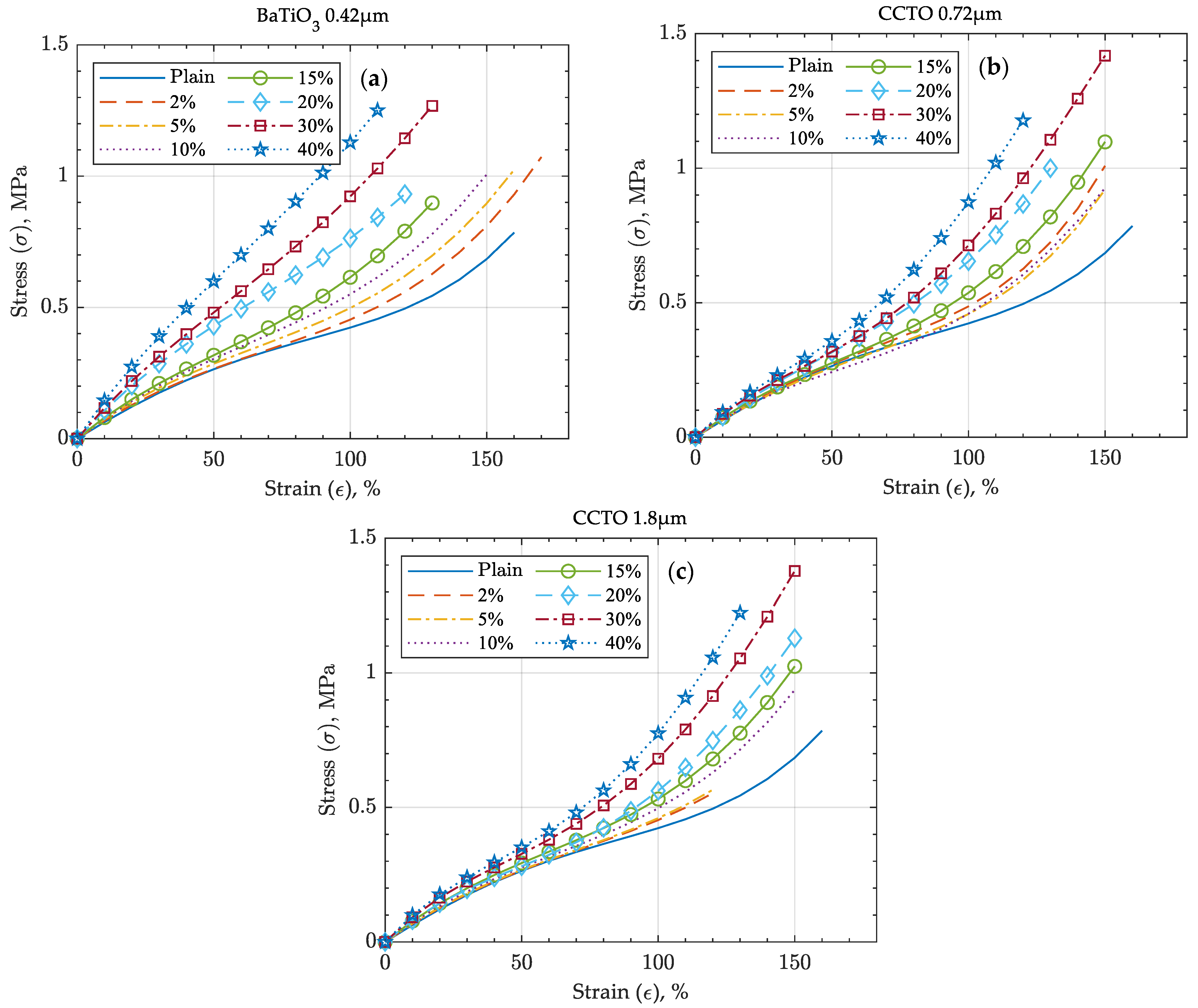
3.2. Mechanical Testing of Dielectrics

Figure 3 shows the effects of fillers on the composites’ Young’s moduli. All three curves display increasing trends as the amounts of fillers increase, validating the elastomer’s stiffness reinforcement. The gradual stiffening validates that none of the composites have reached their mechanical percolation, which is advantageous for DEA’s operation. The upward concavity of the curves agrees with the generalized rule of mixture, often used to represent Young’s modulus of particulate composites:
Y n = Y m n ν m + Y p n ν p
where Y is the Young’s modulus of a composite, v is the volume fraction, indices m and p stand for matrix and particles respectively, and n is a coefficient varying from −1 to 1 [42]. When comparing composites with small and large CCTO fillers, a minor difference in stiffness was observed as the particle loading increased. This also agrees well with common practice as a number of studies concluded that particle size has no effect on the Young’s modulus of micro-composites with filler size greater than 100 nm [36]. It is noteworthy that for both sizes of CCTO, changes in the Young’s modulus are barely observed at weight fractions lower than 15 wt.%. Hence, utilization of low particle loadings of CCTO is possible without penalizing composite softness. This behavior can be observed in several studies where CCTO showed a minor stiffening effect at low particle loadings in PDMS [14,20], polyurethane matrices [15], and even a noticeable softening effect in an epoxy matrix [43]. Lastly, although bulk CCTO has a higher Young’s modulus than bulk BaTiO3 (Table 1), its composites showed a considerably lower stiffening effect than composites with BaTiO3. Besides particles’ Young’s modulus, composites’ stiffness can be affected by an incomplete bonding of particles across their interface area with matrix [44]. In a well-dispersed, degassed particulate composite, such debonding can be caused by stretching a composite with an insufficient particle–matrix interfacial adhesion. Indeed, the preparation of thin tensile coupons usually involves peeling them from a substrate, which applies some stretching to the samples. Additionally, insufficient adhesion can occur when hydrophilic dielectric particles are dispersed in a hydrophobic matrix, e.g., PDMS.

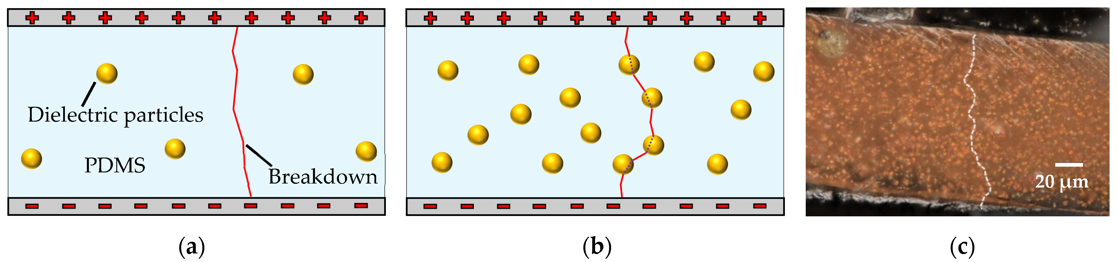
3.3. Breakdown Strength

The loss of breakdown strength in dielectric composites occurs due to a locally distorted and enhanced electric field and a path shortening effect of particles. Electric field is predominantly affected by particles’ agglomeration and size and, in the case of DC breakdowns, the difference in filler’s and matrix’s electrical conductivities [4]. When particles are added to the elastomer matrix to form a two-phase dielectric composite, the breakdown path can be shortened, resulting in a lower breakdown strength. Depending on the amounts of particles in the composite, the breakdown path can go purely through the elastomer (Figure 4a) or involve particles in its path (Figure 4b). If particles are conductive or have lower breakdown strength than the matrix, the breakdown path goes through them, shortening the path through the highly insulating PDMS. Consequently, particles’ amount, size, aspect ratio, alignment, and breakdown strength can influence the composites’ breakdown strength [37,45,46,47].
Figure 5 shows how dielectric strength decreased for all micro-composites with an increase in particle loading. Following the common trend, the composite with small CCTO particles maintained its breakdown strength better than that with large CCTO particles. Due to the small aspect ratio of CCTO particles, the morphology effect on the breakdown strength is neglected. Thus, the difference between the two CCTO-based composites’ breakdown strengths is mainly due to the particle size difference. BaTiO3-based composites showed the highest breakdown strength for most of the particle loading range due to the smaller size, lower conductivity, and higher breakdown strength of the particles (Table 1). Towards the highest filler loading, small CCTO particles showed comparable performance to BaTiO3 particles. Interestingly, CCTO-based composites in the present work maintained breakdown strength noticeably better than those in the referenced study [14]. The absence of particle size and morphology in the original study restricts a comprehensive deduction of the reason behind this difference. However, some variations in the testing procedure, specifically applied voltage increase rate and electrode shape, might have contributed to the result’s difference.
Table 2. Material characterization of prepared dielectric composites.
Material
Composition
ε r   ( )   @ 10 H z Y (MPa) E B   ( V / μ m ) F O M
( D E A )   Normalized
F O M
( S t r a i n )   Normalized
Tensile Strength
σ m a x   ( MPa )
Maximum Strain
δ m a x   ( % )
Maximum Actuaction Thickness Strain ε t   ( % ) 1
Sylgard 184
(15:1 mix ratio)
2.820.67390.3110.98417430.8
BaTiO3
0.42 μm
2%2.910.67690.00.9860.9921.1817230.3
5%3.030.74689.40.9610.9771.0415629.6
10%3.290.74987.80.9120.9510.99914728
15%3.350.81585.70.8570.9261.0613926.3
20%3.611.0384.90.7980.9031.0613324.5
30%4.491.1780.70.6730.8621.3213420.7
40%5.071.4472.40.5430.8291.4312516.7
CCTO
0.72 μm
2%2.950.65689.51.011.021.0615231.1
5%2.890.65588.51.021.051.0615431.3
10%3.20.67186.81.021.091.0915431.3
15%3.290.66685.20.9981.121.1614930.7
20%3.490.72083.00.9641.141.1814129.6
30%3.940.82377.30.861.151.5814026.4
40%4.520.93572.90.7281.121.4913122.4
CCTO
1.8 μm
2%2.940.66189.80.9951.010.62813230.6
5%2.980.66787.60.9871.030.67613330.3
10%3.030.68685.80.9621.061.0615429.6
15%3.180.71183.80.9221.081.0414728.3
20%3.380.71679.60.871.091.1614826.7
30%3.780.79575.10.7361.091.3114322.6
40%3.980.88166.10.5821.071.4213817.9
1 Calculated assuming linear elasticity of the silicone and composite [48].

3.4. Figure of Merit (FOM)

Using the measured composites’ properties, DEA FOMs were calculated and normalized with respect to Sylgard 184 (15:1 A to B part ratio). Figure 6a shows DEA FOM calculated according to Equation (1), which is based on maximum actuation strain. Figure 6b shows a FOM that evaluates actuation strain per unit voltage applied, calculated according to Equation (3):
F O M   ( s t r a i n   p e r   u n i t   v o l t a g e ) = ε r ε 0 Y
As Figure 6a shows, only a marginal improvement in maximum actuation strain can be achieved for a DEA with a small amount of selected CCTO particles. However, as per Figure 6b, considerable improvement in DEA actuation efficiency (strain per unit of applied voltage) can be achieved for both composites with CCTO particles. For the determined optimum composites, the main properties are interpolated in Table 3.

3.5. Pre-Stretched DEA Testing

The composite with 25.7 wt.% of small CCTO particles was actuated and compared to the plain silicone DEA to validate its higher actuation efficiency (Figure 7b–d). Figure 7d shows that the actuation strain per unit of electric field (voltage in case of equally thick films) is higher for the optimized CCTO composite, which validates that FOM was improved. Experimental improvement varies from approximately 15% at lower electric fields to the decreased performance of 8% towards the breakdown. Theoretical improvement should be 15% according to calculated FOM (Table 3). This trend can be explained by the nonlinear elasticity of the materials, which is intentionally neglected in FOMs calculations for uncomplicated material comparisons. The tested composites’ nonlinear material behavior can be conveniently presented in terms of the tangent moduli (Figure 8). According to Figure 8b, at 45% of strain (equivalent to 22.5% of biaxial film pre-stretch), actuation of DEA leads to softening of plain silicone but stiffening of the optimized 25.7 wt.% small-CCTO composite (an imaginary curve could be drawn between the 20 and 30 wt.% curves). This behavior of the materials led to the difference between the predicted optimum FOM and the experimental result.
In addition, the tangent moduli allow for further analysis of the CCTO and BaTiO3 stiffening effects. Similar to the Young’s modulus, the CCTO particle size does not considerably affect stiffening at all strains. It is seen that as the particle loading increases, the tangent moduli vary in relatively smaller ranges, causing BaTiO3 composites to behave more linearly. On the other hand, CCTO composites maintain their nonlinearity. While higher strain results in tangent moduli similar to that observed at lower values for BaTiO3 composites, tangent moduli of CCTO composites are relatively higher at high strains compared to initial values (Young’s moduli). However, the higher stiffness of CCTO composites towards its stretchability limit can hardly be considered a significant drawback, as DEAs typically operate at strains far from the maximum elongation of the elastomer material. In fact, this behavior contributes towards the DEA’s electromechanical stability. Therefore, the tangent modulus can be used not only for correcting performance prediction using conventional FOMs, but also for choosing the optimum degree of pre-stretch so that DEA operates in its lowest stiffness range.

4. Conclusions

This work studied the effects of particle loading and size on CCTO/PDMS dielectric composites for DEA applications and compared them to conventionally used BaTiO3 particles. Relative dielectric permittivity, Young’s modulus, and breakdown strength were experimentally determined to characterize the tested composites. Compared to other studies on CCTO/PDMS composites, current results with Sylgard 184 showed lower permittivity values but higher breakdown strength, emphasizing the importance of the compatibility of matrix and particles. The CCTO composites’ Young’s moduli started increasing at about 15 wt.% of filler loading and, overall, showed lower stiffening effects than BaTiO3. It allowed CCTO-based DEA to achieve significantly better performance, as shown by FOMs, even though the BaTiO3/PDMS composite possessed higher permittivity and breakdown strength. It was shown that for CCTO, even moderately smaller particles (with the six times larger specific surface area) achieved considerably greater performance in permittivity and breakdown strength, while having minor effects on Young’s modulus. FOMs were used to determine the optimum filler loading for dielectric composites with CCTO and BaTiO3 particles. While no optimum filler loading was found for BaTiO3, both types of CCTO composites maximized their performance at filler loadings outside the previously studied range (9 wt.%). Particularly, in this study, the optimum filler loading for CCTO was found to be 25.1–25.7 wt.% depending on the particle size. Electromechanical testing of the DEA made of the optimized composite with small CCTO particles solidified the improved material performance, while highlighting differences between theoretical FOM and actual DEA performance. Finally, composites’ elasticity was further studied through tangent moduli, which revealed the reasons behind the differences in theoretical FOM and results of electromechanical testing.

Author Contributions

Conceptualization, methodology: S.S., D.T.M. and A.E.A.; investigation, validation, data curation, writing—original draft preparation: S.S. and D.T.M.; software, formal analysis, visualization: S.S.; writing—review and editing: S.S., D.T.M., A.E.A., E.D. and D.K.; resources: E.D. and D.K.; supervision: D.K.; project administration, S.S. and D.K. All authors have read and agreed to the published version of the manuscript.

Funding

This research received no external funding.

Institutional Review Board Statement

Not applicable.

Informed Consent Statement

Not applicable.

Data Availability Statement

Data are contained within the article.

Conflicts of Interest

The authors declare no conflict of interest.

Appendix A

Figure A1. Size distribution of particles used for dielectric composites.
Actuators 10 00137 g0a1
Figure A2. Stress-strain curves of the tested PDMS composites with: (a) BaTiO3, (b) small CCTO, and (c) large CCTO.
Actuators 10 00137 g0a2
Figure A3. Pre-stretched DEA test results as observed.
Actuators 10 00137 g0a3
Table A1. Experimental results of biaxial electromechanical testing.
Material
Composition
Thickness t
(μm)
Applied   E (V/μm) and ( its   %   of   the   Material   E B ) Max Thickness Actuation
Strain   Reached   ε t   ( % )
Sylgard 184
(15:1 mix ratio)
78.680.2 (88.8%)−17.3
CCTO 0.72 μm
25.7 wt.%
89.666.3 (83.0%)−13.5

Appendix B

Supplemental materials for film preparation and actuation test:
  • Poly(acrylic acid) (MilliporeSigma, Burlington, MA, USA, part #523925) aqueous 35 wt.% solution of poly(acrylic acid) used for a sacrificial layer in the film preparation procedure.
  • Isopropanol (M.G. Chemicals Ltd., Burlington, ON, Canada, part #824) used for dissolving poly(acrylic acid).
  • Carbon conductive grease (M.G. Chemicals Ltd., part #846) used as pre-stretched DEA electrode material with a resistivity of 117 Ω·cm.
Thin films of dielectric composites with three ceramic fillers were prepared according to an existing well-developed technique [38], whose procedure was adopted as follows:
1.
125 μm PET films were placed on a vacuum plate to ensure their flatness.
2.
A sacrificial layer was applied using an applicator Zehntner ZUA2000 (Zurich, Switzerland) on each PET film. A 35 wt.% aqueous solution of poly(acrylic acid) was mixed with isopropanol in a 1:6 ratio to reach a 5 wt.% concentration of poly(acrylic acid) in the sacrificial solution.
3.
As the sacrificial layer dried out, material compositions were applied by manually operating the applicator. By setting the applicator to 500 μm, films with thicknesses of about 320 μm (thick film) were produced for mechanical and dielectric permittivity testing. For breakdown strength and biaxial electromechanical tests, 100 μm thick films (thin film) were produced by setting the applicator to 200 μm. It was noticed that higher application speed for the manually operated applicator provided better thickness evenness of the film.
4.
Finally, samples were cured in a Grieve SA-550 air furnace (Round Lake, IL, USA) at 100 °C for 45 min and cut into testing coupons.
Prepared nanocomposite films lost almost all their transparency at particle loading of 2–5 wt.%. Thus, both MTI-Instruments DTS-120-40 laser displacement sensor (Albany, NY, USA) and Fowler IP54 disk micrometer (Newton, MA, USA) measured each sample’s final thicknesses. When the micrometer was used for nanocomposite films, thickness values were analytically corrected by considering the measured Young’s moduli and the compressive force of 5 N.

References

  1. Hines, L.; Petersen, K.; Lum, G.Z.; Sitti, M. Soft Actuators for Small-Scale Robotics. Adv. Mater. 2017, 29, 1603483. [Google Scholar] [CrossRef] [PubMed]
  2. Sommer-Larsen, P.; Larsen, A. Materials for dielectric elastomer actuators. In Proceedings of the SPIE Smart Structures and Materials, San Diego, CA, USA, 27 July 2004; pp. 67–77. [Google Scholar]
  3. Madsen, F.B.; Daugaard, A.E.; Hvilsted, S.; Skov, A.L. The Current State of Silicone-Based Dielectric Elastomer Transducers. Macromol. Rapid Commun. 2016, 37, 378–413. [Google Scholar] [CrossRef] [PubMed] [Green Version]
  4. Barber, P.; Balasubramanian, S.; Anguchamy, Y.; Gong, S.; Wibowo, A.; Gao, H.; Ploehn, H.J.; zur Loye, H.-C. Polymer Composite and Nanocomposite Dielectric Materials for Pulse Power Energy Storage. Materials 2009, 2, 1697–1733. [Google Scholar] [CrossRef]
  5. Zhou, L.; Jiang, Y. Recent progress in dielectric nanocomposites. Mater. Sci. Technol. 2020, 36, 1–16. [Google Scholar] [CrossRef]
  6. Panahi-Sarmad, M.; Zahiri, B.; Noroozi, M. Graphene-based composite for dielectric elastomer actuator: A comprehensive review. Sens. Actuators A Phys. 2019, 293, 222–241. [Google Scholar] [CrossRef]
  7. Vaicekauskaite, J.; Mazurek, P.; Vudayagiri, S.; Ladegaard Skov, A. Silicone elastomer map: Design the ideal elastomer. In Proceedings of the SPIE Smart Structures + Nondestructive Evaluation, Denver, CO, USA, 13 March 2019. [Google Scholar]
  8. Shintake, J.; Matsuno, K.; Baba, K.; Takeuchi, H. Characterization of dielectric elastomer actuators made of slide ring materials. In Proceedings of the SPIE Smart Structures + Nondestructive Evaluation, Denver, CO, USA, 13 March 2019. [Google Scholar]
  9. Yu, L.; Madsen, F.; Hvilsted, S.; Skov, A. Dielectric elastomers, with very high dielectric permittivity, based on silicone and ionic interpenetrating networks. RSC Adv. 2015, 5. [Google Scholar] [CrossRef] [Green Version]
  10. Yoon, J.R.; Han, J.-W.; Lee, K.-M. Dielectric Properties of Polymer-ceramic Composites for Embedded Capacitors. Trans. Electr. Electron. Mater. 2009, 10, 116–120. [Google Scholar] [CrossRef] [Green Version]
  11. Lotz, P.; Matysek, M.; Lechner, P.; Hamann, M.; Schlaak, H. Dielectric elastomer actuators using improved thin film processing and nanosized particles. In Proceedings of the SPIE Smart Structures + Nondestructive Evaluation, San Diego, CA, USA, 10 April 2008. [Google Scholar] [CrossRef]
  12. Ahmadipour, M.; Ain, M.F.; Ahmad, Z.A. A Short Review on Copper Calcium Titanate (CCTO) Electroceramic: Synthesis, Dielectric Properties, Film Deposition, and Sensing Application. Nano Micro Lett. 2016, 8, 291–311. [Google Scholar] [CrossRef] [Green Version]
  13. Romasanta, L.; Leret, P.; Casaban, L.; Hernández, M.; Rubia, M.; Fernández, J.; Kenny, J.; Lopez-Manchado, M.; Verdejo, R. Towards materials with enhanced electro-mechanical response: CaCu3Ti4O12–polydimethylsiloxane composites. J. Mater. Chem. 2012, 22, 24705–24712. [Google Scholar] [CrossRef] [Green Version]
  14. Vudayagiri, S.; Zakaria, S.; Yu, L.; Hassouneh, S.; Benslimane, M.; Skov, A. High breakdown-strength composites from liquid silicone rubbers. Smart Mater. Struct. 2014, 23, 105017. [Google Scholar] [CrossRef]
  15. Wan, W.; Luo, J.; Huang, C.-E.; Yang, J.; Feng, Y.; Yuan, W.-X.; Ouyang, Y.; Chen, D.; Qiu, T. Calcium copper titanate/polyurethane composite films with high dielectric constant, low dielectric loss and super flexibility. Ceram. Int. 2017. [Google Scholar] [CrossRef]
  16. Wang, J.; Chao, X.; Li, G.; Feng, L.; Zhao, K. Fabrication and enhanced characterization of copper powder filled copper calcium titanate/poly(vinylidene difluoride) composite. J. Mater. Sci. Mater. Electron. 2016, 28, 1–5. [Google Scholar] [CrossRef]
  17. Duan, L.; Wang, G.; Zhang, Y.; Zhang, Y.; Wei, Y.; Wang, Z.; Zhang, M. High dielectric and actuated properties of silicone dielectric elastomers filled with magnesium-doped calcium copper titanate particles. Polym. Compos. 2016. [Google Scholar] [CrossRef]
  18. Zhang, Y.Y.; Wang, G.L.; Zhang, J.; Ding, K.H.; Wang, Z.F.; Zhang, M. Preparation and properties of core-shell structured calcium copper titanate@ polyaniline/silicone dielectric elastomer actuators. Polym. Compos. 2019, 40, E62–E68. [Google Scholar] [CrossRef]
  19. Babu, S.; Singh, K.; Govindan, A. Dielectric properties of CaCu3Ti4O12—Silicone resin composites. Appl. Phys. A 2012, 107. [Google Scholar] [CrossRef] [Green Version]
  20. Wang, G.; Zhang, Y.; Duan, L.; Ding, K.; Wang, Z.; Zhang, M. Property reinforcement of silicone dielectric elastomers filled with self-prepared calcium copper titanate particles. J. Appl. Polym. Sci. 2015, 132. [Google Scholar] [CrossRef]
  21. Zhang, Y.-Y.; Min, Y.; Wang, G.-L.; Wang, Z.-F.; Junliang, L.; Luo, Z.-W.; Zhang, M. Design and properties of calcium copper titanate/poly(dimethyl siloxane) dielectric elastomer composites. Rare Met. 2019. [Google Scholar] [CrossRef]
  22. Fralick, B.S.; Gatzke, E.P.; Baxter, S.C. Three-dimensional evolution of mechanical percolation in nanocomposites with random microstructures. Probabilistic Eng. Mech. 2012, 30, 1–8. [Google Scholar] [CrossRef] [Green Version]
  23. Sakakibara, T.; Izu, H.; Kura, T.; Shinohara, W.; Iwata, H.; Kiyama, S.; Tsuda, S. High-voltage photovoltaic micro-devices fabricated by a new laser-processing. In Proceedings of the IEEE 5th International Symposium on Micro Machine and Human Science, Nagoya, Japan, 2–4 October 1994; p. 75. [Google Scholar]
  24. Tunkasiri, T.; Rujijanagul, G. Dielectric strength of fine grained barium titanate ceramics. J. Mater. Sci. Lett. 1996, 15, 1767–1769. [Google Scholar] [CrossRef]
  25. Branwood, A.; Hurd, J.D.; Tredgold, R.H. Dielectric breakdown in barium titanate. Br. J. Appl. Phys. 1962, 13, 528. [Google Scholar] [CrossRef]
  26. Scott, J.F.; Azuma, M.; Paz de Araujo, C.A.; McMillan, L.D.; Scott, M.C.; Roberts, T. Dielectric breakdown in high-ε films for ULSI DRAMs: II. barium-strontium titanate ceramics. Integr. Ferroelectr. 1994, 4, 61–84. [Google Scholar] [CrossRef]
  27. Ertuğ, B. The Overview of the Electrical Properties of Barium Titanate. Am. J. Eng. Res. 2013, 2, 1–7. [Google Scholar]
  28. Ertuğ, B. Electrical Conductivity and Hysteresis Characteristic of BaTiO3-Based Sensors with Polymethyl metacrylate (PMMA) Pore Former. Sens. Mater. 2013, 25, 309–321. [Google Scholar]
  29. Subramanian, M.; Li, D.; Duan, N.; Reisner, B.; Sleight, A. High dielectric constant in a ACu3Ti4O12 and ACu3Ti3FeO12 phases. J. Solid State Chem. 2000, 151, 323–325. [Google Scholar] [CrossRef]
  30. Ramírez, M.; Parra, R.; Reboredo, M.; Varela, J.; Castro, M.M.; Ramajo, L. Elastic modulus and hardness of CaTiO3, CaCu3Ti4O12 and CaTiO3/CaCu3Ti4O12 mixture. Mater. Lett. 2010, 64, 1226–1228. [Google Scholar] [CrossRef]
  31. Li, T.; Chen, Z.; Chang, F.; Hao, J.; Zhang, J. The effect of Eu2O3 doping on CaCu3Ti4O12 varistor properties. J. Alloy. Compd. 2009, 484, 718–722. [Google Scholar] [CrossRef]
  32. Cheng, B.; Lin, Y.-H.; Deng, W.; Cai, J.; Lan, J.; Nan, C.-W.; Xiao, X.; He, J. Dielectric and nonlinear electrical behaviors of Ce-doped CaCu3Ti4O12 ceramics. J. Electroceram. 2012, 29, 250–253. [Google Scholar] [CrossRef]
  33. Tang, Z.; Wu, K.; Huang, Y.; Li, J. High Breakdown Field CaCu3Ti4O12 Ceramics: Roles of the Secondary Phase and of Sr Doping. Energies 2017, 10, 1031. [Google Scholar] [CrossRef] [Green Version]
  34. Samarakoon, D.P.; Govindaraju, N.; Singh, R.N. Dielectric Properties of Calcium Copper Titanate Ceramics Exposed to Air and Dry Nitrogen Atmospheres. Trans. Indian Inst. Met. 2019, 72, 2035–2041. [Google Scholar] [CrossRef]
  35. Santiago-Alvarado, A.; Cruz-Felix, A.; Iturbide, F.; Licona-Morán, B. Physical-chemical properties of PDMS samples used in tunable lenses. Int. J. Eng. Sci. Innov. Technol. 2014, 3, 563–571. [Google Scholar]
  36. Fu, S.-Y.; Feng, X.-Q.; Lauke, B.; Mai, Y.-W. Effects of particle size, particle/matrix interface adhesion and particle loading on mechanical properties of particulate–polymer composites. Compos. Part. B Eng. 2008, 39, 933–961. [Google Scholar] [CrossRef]
  37. Wang, Z.; Keith Nelson, J.; Hillborg, H.; Zhao, S.; Schadler, L.S. Dielectric constant and breakdown strength of polymer composites with high aspect ratio fillers studied by finite element models. Compos. Sci. Technol. 2013, 76, 29–36. [Google Scholar] [CrossRef]
  38. Rosset, S.; Araromi, O.; Schlatter, S.; Shea, H. Fabrication Process of Silicone-based Dielectric Elastomer Actuators. J. Vis. Exp. 2015, 2016. [Google Scholar] [CrossRef] [PubMed] [Green Version]
  39. Carpi, F.; Anderson, I.; Bauer, S.; Frediani, G.; Gallone, G.; Gei, M.; Graaf, C.; Jean-Mistral, C.; Kaal, W.; Kofod, G.; et al. Standards for dielectric elastomer transducers. Smart Mater. Struct. 2015, 24, 105025. [Google Scholar] [CrossRef] [Green Version]
  40. Nawanil, C.; Makcharoen, W.; Khaosa-Ard, K.; Maluangnont, T.; Vittayakorn, W.; Isarakorn, D.; Vittayakorn, N. Electrical and dielectric properties of barium titanate—Polydimethylsiloxane nanocomposite with 0–3 connectivity modified with carbon nanotube (CNT). Integr. Ferroelectr. 2019, 195, 46–57. [Google Scholar] [CrossRef]
  41. Sappati, K.k.; Bhadra, S. 0–3 Barium Titanate-PDMS Flexible Film for Tactile Sensing. In Proceedings of the 2020 IEEE International Instrumentation and Measurement Technology Conference (I2MTC), Dubrovnik, Croatia, 25–28 May 2020; pp. 1–6. [Google Scholar]
  42. Hosford, W.F. Mechanical Behavior of Materials, 2nd ed.; Cambridge University Press: Cambridge, UK, 2009. [Google Scholar]
  43. Dandan Satia, M.S.; Jaafar, M.; Julie, M. Properties of calcium copper titanate and barium titanate filled epoxy composites for electronic applications: Effect of filler loading and hybrid fillers. J. Mater. Sci. Mater. Electron. 2014, 25, 4923–4932. [Google Scholar] [CrossRef]
  44. Teng, H. Stiffness properties of particulate composites containing debonded particles. Int. J. Solids Struct. 2010, 47, 2191–2200. [Google Scholar] [CrossRef] [Green Version]
  45. Molberg, M.; Crespy, D.; Rupper, P.; Nüesch, F.; Månson, J.-A.E.; Löwe, C.; Opris, D.M. High Breakdown Field Dielectric Elastomer Actuators Using Encapsulated Polyaniline as High Dielectric Constant Filler. Adv. Funct. Mater. 2010, 20, 3280–3291. [Google Scholar] [CrossRef]
  46. Yang, X.; Hu, J.; Chen, S.; Jinliang, H. Understanding the Percolation Characteristics of Nonlinear Composite Dielectrics. Sci. Rep. 2016, 6, 30597. [Google Scholar] [CrossRef] [Green Version]
  47. Cai, Z.; Wang, X.; Luo, B.; Hong, W.; Wu, L.; Li, L. Dielectric response and breakdown behavior of polymer-ceramic nanocomposites: The effect of nanoparticle distribution. Compos. Sci. Technol. 2017, 145, 105–113. [Google Scholar] [CrossRef]
  48. Wissler, M.; Mazza, E. Modeling of a pre-strained circular actuator made of dielectric elastomers. Sens. Actuators A Phys. 2005, 120, 184–192. [Google Scholar] [CrossRef]
Figure 1. SEM images of dielectric particles: (a) BaTiO3 ( d a v g = 0.42 μm), (b) small CCTO ( d a v g = 0.72 μm), (c) large CCTO ( d a v g = 1.8 μm). A more detailed particle size analysis is presented in Appendix A Figure A1.
Actuators 10 00137 g001
Figure 2. (a) Effect of particles’ permittivity on the dielectric composite permittivity according to Bruggeman’s model [4] (for matrix permittivity ε m = 2.8 ). At lower volume filler loading, particles’ permittivity has a minor effect on the final dielectric composite permittivity (40 wt.% of BaTiO3 and CCTO equates to 10.8 and 12.8 vol.%, respectively). (b) Relative dielectric permittivity per weight fraction of BaTiO3/PDMS and CCTO/PDMS composites. Tested on 50 by 50 mm, 320 μm thick coupons. Each data point represents mean value and SD of 8 coupons tested.
Actuators 10 00137 g002
Figure 3. Young’s modulus of BaTiO3/PDMS and CCTO/PDMS dielectric composites. Tested on 10 by 70 mm, 320 μm thick coupons. Each data point represents mean value and SD of 5 coupons tested. Stress-strain curves of the tested composites are presented in Appendix A Figure A2.
Actuators 10 00137 g003
Figure 4. (a,b) Potential breakdown paths in dielectric composites illustrated based on the amount of filler particles and (c) estimated path from the actual CCTO/PDMS composite DEA, connecting closely placed particles (image taken with a digital microscope Keyence VHX-7000 Series (Itasca, IL, USA)). In (b), while dotted lines inside the particles do not represent an authentic path of breakdown, the nature of the breakdown strength loss can be illustrated.
Actuators 10 00137 g004
Figure 5. Breakdown strength of BaTiO3/PDMS and CCTO/PDMS dielectric composites. Tested on 100 μm thick films. Each data point represents the mean value and SD of 10 measurements.
Actuators 10 00137 g005
Figure 6. FOMs for (a) maximum actuation strain, and (b) actuation strain per unit voltage applied.
Actuators 10 00137 g006
Figure 7. Pre-stretched DEA testing. (a1) A circle (sized according to the desired pre-stretch) was marked on a silicone or dielectric composite film, (a2) the film was manually pre-stretched until the pre-marked circle matched the circular frame, (a3) pre-stretched film was fixed on the frame, (a4) carbon grease electrodes were brushed on both sides of the pre-stretched film, (a5) voltage was applied to electrodes while monitoring the actuation. Plain silicone and optimized CCTO/PDMS dielectric composite DEAs (b1,c1) at 0 V and (b2,c2) at maximum voltage applied, respectively. (d) Experiment results for thickness actuation of both DEAs and improved FOM (strain) of optimized CCTO/PDMS over plain PDMS. Thickness strain and electric field are calculated from the observed electrode radial expansion vs. applied voltage (Appendix A Figure A3 and Table A1), assuming incompressibility and linear elasticity of the silicone and composite [48].
Actuators 10 00137 g007
Figure 8. Tangent moduli as functions of strain of dielectric composites with different particle loadings (as shown in the legends) of (a) BaTiO3, (b) small CCTO, and (c) large CCTO particles.
Actuators 10 00137 g008
Table 1. Properties of bulk BaTiO3 and CCTO ceramics.
FillerRelative Permittivity (−)Young’s Modulus (GPa)Breakdown Strength (V/μm)Electrical Conductivity (S/cm)
BaTiO36000 [3]67 [23]2–24 1 [24,25,26]1–2.5 × 10⁻⁹ [27,28]
CCTO10,000–100,000 [12,29]256 [30]0.05–0.2 1 [31,32,33]5 × 10⁻⁸ 2
1 Values vary based on crystal size, purity, and testing ceramic film porosity. 2 Calculated from the data in [34].
Table 3. Interpolated material properties of dielectric composites with the optimum particle loading.
Material
Composition
ε r (−) @ 10 H z Y (MPa) E B (V/μm) F O M
( D E A )   Normalized
F O M
( S t r a i n )   Normalized
Tensile Strength
σ m a x   ( MPa )
Maximum Strain
δ m a x   ( % )
Maximum Actuaction Thickness Strain ε t   ( % )
Sylgard 184
(15:1 mix ratio)
2.820.67390.3110.98417430.8
CCTO 0.72 μm
6.8 wt.%
3.020.66688.01.0151.071.0715431.4
CCTO 0.72 μm
25.7 wt.%
3.750.76180.20.9051.151.4114628
CCTO 1.8 μm
25.1 wt.%
3.530.75677.50.8021.091.2314524.8
Publisher’s Note: MDPI stays neutral with regard to jurisdictional claims in published maps and institutional affiliations.

