Abstract
Electroactive polymers (EAPs), especially dielectric elastomer actuators (DEAs), belong to a very promising and emerging class of functional materials. While DEAs are mostly utilized to rely on carbon-based electrodes, there are certain shortcomings of the use of carbon electrodes in the field of soft robotics. In this work we present a fish-like bending structure to serve as possible propulsion element, completely avoiding carbon-based electrodes. The presented robot is moving under water, using a particularly tailored conductive hydrogel as inner electrode and a highly anisotropic textile material to manipulate the bending behavior of the robot. The charge separation to drive two DEAs on the outsides of the robot is provided by the conductive hydrogel while the surrounding water serves as counter electrode. To characterize the hydrogel, tensile tests and impedance spectroscopy are used as measurement methods of choice. The performance of the robot was evaluated using a digital image correlation (DIC) measurement for its bending deflections under water. The developed fish-like robot was able to perform a dynamic bending movement, based on a tri-stable actuator setup. The performed measurements underpin the sufficient characteristics for an underwater application of conductive hydrogel electrodes as well as the applicability of the robotic concept for under water actuations.
1. Introduction
Current developments in the field of EAPs are continuously creating new concepts and drive solutions with remarkable innovative momentum. One of the most promising classes of EAPs are the dielectric elastomers (DE) and the corresponding dielectric elastomer actuators. While a lot of effort is already put into optimizing their force output and efficiency, the demand on reliable electrodes allowing large deformations seems still not sufficiently solved. Established robotic concepts using DEAs mostly rely on carbon-based electrodes [1,2]. Such electrodes use a base material with infiltrated conductive particles like carbon black [3] or carbon nanotubes [4], compatible with the dielectric material. The existing trade-off with carbon-based electrodes lies in complementary mechanical (high deformations) and electrical (sufficient conductivity) properties. However, the optimal scenario for DEA-electrodes lies in perfectly conductive electrodes that are completely compliant. While an increase of filler content leads to increased electrical conductivity, the mechanical stiffness also increases. To provide a solution for that shortcoming, Carpi et al. demonstrated the feasibility of using conductive liquid electrodes for DEAs [5]. This work here proposes an alternative approach. By utilizing a conductive hydrogel, a robotic concept is developed to serve as possible propulsion mechanism in underwater setups. Since hydrogels are based on hydrophilic polymer structures, a great advantage is offered, everywhere a use in humid surroundings is desired [6]. The presented robot is designed to act in exactly such surroundings, since they represent a relevant case for many soft-robotic applications.
For such applications, the use of a tailored hydrogel as electrode material offers a promising alternative to the established approaches. In contrast to silicone carbon compound electrodes, three types of conductive hydrogels as electrode material are promising: conducting polymer hydrogels, micro or nanocomposite hydrogels and ionically conductive hydrogels [7].
In an ionically conductive hydrogel, as we use it here, the conductivity depends on the amount and the type of ions, as well as the interaction of the ions with the polymer network and the amount of water infiltrated into it. The interaction of the ions with the polymer network can be influenced by the type of monomer (charged/uncharged) as well as the degree of crosslinking, which in turn determines the elasticity of the hydrogel [8]. Keplinger et al. reported an ionic conductivity of a hydrogel with incorporated anorganic salts close to the conductivity in solution of the same salts [9]. In contrast to rigid nano- or microparticles, like carbon, the amount of ions does not have a large impact on the elasticity of the hydrogel, enabling comparatively low elastic moduli with adequate conductivities, respectively, polarizability of the charge carriers [10]. However, these properties only apply to the as-prepared state of the hydrogel. Salting out of ionic hydrogels must be avoided with a waterproof encapsulation and is usually given due to the embedding in form-giving silicone and the attached DE membrane [11]. Furthermore, dehydration of the hydrogel within the soft robotics application is in turn prevented by its use in water. Due to these properties, an application of hydrogel electrodes in aqueous environments or underwater is predestined.
Underwater robots for the investigation of reefs and maritime life [12] for example are gaining interest in recent years. These robots are performing propulsory movements in water [13] and are either remote-controlled [14] or even untethered and autonomous, like the octobot [15]. Developments of pure electroactive structures acting underwater are comparatively few. While most of the yet developed concepts rely on pneumatic [16] or hydraulic [12] actuation, pure electroactive concepts are still a marginal trend. There are some bending structures, generating propulsion by consecutively switching DEAs either in a carbon-based setup [17] or by using a conductive fluid to provide charge separation [18]. For robotic applications like these, the use of a hydrogel as electrode material offers a promising alternative to the established approaches.
The application of conductive hydrogels with such properties in electroactive setups to build up a DEA is up to now realized only for selected combinations of dielectric elastomers and different types of hydrogels. Keplinger [9] demonstrated a transparent hydrogel based on polyacrylamide as electrode material on an acrylic dielectric to build up a DEA to act as a loudspeaker. Such concepts for hydrogel electrodes mostly rely on acrylic dielectrics [19], sometimes used with additional carbon-nanotube fillers [20].
Here we present a fish-like structure performing a bending motion under water. We used an ionic hydrogel based on polyacrylamide to conduct charge to the inner side of a silicone-based dielectric. The outer electrode, having direct contact to the surrounding water, was provided with charge transport using the water itself. In this way the robot generates an undulating wave towards the end of the fin as possible propulsion method, similar to other fish-like robots [21,22].
In contrast to other robots swimming in water [11], the here presented robot uses two DEAs to consecutively control the direction of the bending since its initial state is straight. This alignment is achieved by incorporating a unidirectional textile material, consisting of glass fibers, right in the neutral plane of the robot. That setup ensures a straight alignment of the robot by applying two pre-stretched dielectric membranes on both outer sides of it. The hydrogel is encapsulated inside two chambers of the robot’s body so that the DEAs can be switched separately and it is safe from shortcuts to the surrounding water and will not dispergate and lose its properties.
In the following we present the robotic concept, the design and fabrication methods as well as the mechanical and electrical characterization of the ionic hydrogel as operating material. Displacement measurements of the soft fish-fin robot in water demonstrate the application of hydrogels in the field of textile-reinforced electroactive structures. In particular, the following aspects will be taken into focus:
- The use of equi-biaxial pre-stretched dielectric membranes on a unidirectionally acting setup;
- The use of a tailored textile material to manipulate the mechanical behavior of a soft actuator structure;
- The use of an ionic hydrogel to enable charge separation on the surfaces of the dielectric membrane;
- The complete avoidance of carbon-based electrodes in an underwater robotic setup;
- The implementation of two bending directions, resulting in three defined bending states.
2. Materials and Methods
2.1. Robotic Concept
The robotic concept makes use of a tailored textile material to manipulate the mechanical properties of the whole structure. A textile material HP-U400E (HP-Textiles, Schapen, Germany) with an areal weight of 457 was used for the construction of the robot. The material consists of unidirectionally oriented parallel glass fibers and was placed in the neutral plane of the robotic setup. The highly anisotropic mechanical properties of the uniaxial fibers ensures that an equi-biaxial stretch state of the dielectric membranes can be taken up, leading to a preferred bending direction orthogonal to the fiber direction. Around the textile layer, a silicone matrix was cast in a geometry that gives the functional shape of the robot. The silicone casting serves several requirements.
- It infiltrates the textile material and serves as matrix material to form a stable and defined compound.
- It defines the structure of the fish-fin geometry and gives its shape.
- It provides the cavities for the introduced hydrogel at the positions for the DEA electrodes.
- It defines the out-of-plane distance for the DEAs to generate the bending movement.
The dimensions of the robot and the positions of the cavities for the hydrogel are given in Figure 1. Figure 2 depicts the layered setup of the robot together with the layer thicknesses.
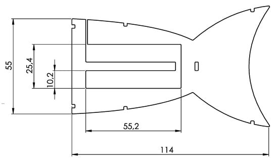
Figure 1.
Dimensions of the fish fin structure as the core part of the robot’s body in mm. Rectangle parts represent void spaces down to the neutral plane, providing cavities for the hydrogel.
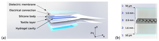
Figure 2.
Layered setup of (a) the robot with DEAs on both outer sides and (b) the symmetric arrangement of single layers and their corresponding thicknesses consisting of the dielectric films for the DEAs (1), the silicone layer with the included hydrogel cavities of the same thickness (2) and the textile layer (3) in the neutral plane.
The casting of the inner structure was carried out using the silicone material Sylgard 184 (Dow Corning, Midland, USA). The used cast mold was manufactured according to the geometrical design of the robot with respect to Figure 1 and Figure 2. The DEAs on both outer sides of the robot consisted of a silicone-based material Elastosil 2030 (Wacker, München, Germany). The membranes are equi-biaxially pre-stretched to a ratio of 1.5, leading to a membrane thickness of 22.2 μm in the stretched state. Afterwards the dielectric membranes were attached to the inner structure using Sylgard 184. In that step, also the electrical wiring was placed and encapsulated under the dielectric membranes with the silicone glue. After the materials were crosslinked and cured, the hydrogel was injected into the cavities using multiple cannulas. Therefore, the pre-mixed hydrogel solution was injected after the polymerization to crosslink right in the desired position of the cavities. Afterwards, the cannulas were removed and the penetrations were sealed with silicone.
The robotic concept aims to perform a tri-stable bending motion, induced by selectively activating the DEAs on the outer sides of the robot. Figure 3 gives an overview on the principle of the implemented stable bending states. To date, the robotic concept does not follow the aim of freely swimming under water. Since the bending motion is to be shown and evaluated, the design follows the approach to be able to clamp the robot at its front end (x = 0). Once the possible use as a driving mechanism is proven, the concept will be redesigned in a future study to be freely swimming and using the developed bending concept as driving element.
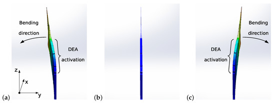
Figure 3.
Tri-stable bending principle of the robotic concept: (a) bending to the left side by activating the DEA on the right side; (b) initial straight configuration without activation of any DEA; (c) bending to the right side by activating the DEA on the left side.
2.2. Synthesis of the Hydrogel
For the synthesis of 5 mL ionic hydrogel, acrylamide (1.0 g, Sigma Aldrich, St. Louis, MI, USA), N,N’-methylene-bis-acrylamide (0.7 mg, Sigma Aldrich, St. Louis, MI, USA) and sodium chloride (876.6 mg, Sigma Aldrich, St. Louis, MI, USA) were dissolved in 3.699 mL ultrapure water. Before free-radical polymerization was started by adding ammonium peroxodisulfate (10.3 mg, Sigma Aldrich, St. Louis, MI, USA) and N,N,N’,N’-tetramethylethylenediamine (10.2 µL, Carl Roth, Karlsruhe, Germany), the pre-gel solution was ice-cooled. Afterwards, the still liquid and ice-cooled hydrogel solution was applied to the required sample mold with a pipette and polymerized at room temperature. An individual hydrogel volume per sample was needed depending on the usage: 1.35 mL per cavity for the robotic application, 400 µL per round mold for the electrical measurement and 2 mL per rod mold for the tensile test. The samples for the electrical measurements had a cylindrical geometry with a diameter of 13 mm and a height of 3 mm. The samples for the tensile test followed the geometry of shoulder rods with a thickness of 2.2 mm and a width of 6 mm. The hydrogel samples used for all the measurements were stored under stable conditions. The measurements were carried out within 24 h after the synthesis. The samples were stored in separate, sealed boxes with an additional set of water-infiltrated towels within to ensure high humidities. Each sample was packed separately to remain the other samples inert during measurement.
2.3. Mechanical Characterization
To evaluate the mechanical properties and the compliance of the used materials, uniaxial tensile tests were carried out using a tensile testing machine Zwick-Roell Z050. For the measurements a force transducer for maximum forces of 100 N was used. The tensile tests were carried out according to the standard DIN 53504 with a pulling speed of 500 . The data preparation included post-processing of the data to calculate the stresses from the measured forces and the stretch ratios from the measured elongations.
2.4. Electrical Characterization: Impedance Spectroscopy
The aim of the performed EIS measurement was to proof that a sufficient conductivity of the hydrogel is given for the desired application as DEA electrodes. The electrical characterization of the hydrogel was carried out with the as-prepared samples. A self-designed measuring cell was used to measure the prepared samples, cast in the optimized geometry specifically for this analysis method. The measuring cell (see Figure 4) for electrical impedance spectroscopy (EIS) comprises an aluminum block (80 × 60 × 53 mm) in which two heating cartridges and temperature sensors (Horst, Lorsch, Germany) are integrated, connected to an external temperature controller (Horst, Lorsch, Germany) to ensure a constant measuring temperature. The sample is located between two copper electrodes, which are connected to a potentiostat PGSTAT302N (Metrohm Autolab, Utrecht, Netherlands) with Frequency Response Analyzer (FRA module). The cell is situated in a Faraday cage. The potentiostat was calibrated by the manufacturer, the functionality of the FRA module was verified via a dummy cell with R(RC) circuit (Autolab dummy cell 2, Metrohm Autolab, Utrecht, The Netherlands) and specific calibration factors were determined using the provided Faraday cage and the shielded measuring cables of the setup.
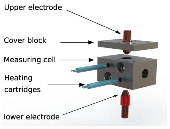
Figure 4.
Concept of the measurement cell with heating cartridges and copper electrodes to contact the sample inside of an aluminium block.
The impedance data was analyzed by the software NOVA 2.1.5 integrated into the potentiostat. The upper electrode (working electrode) of the assembly has a conical frustum shape with a base radius of 6.4 mm and a top radius of 2.4 mm. The lower electrode (counter electrode) has a cylindrical shape with a radius of 4 mm. The upper electrode is located in the lid of the aluminum block. This lid is screwed to the body of the block after the sample is placed onto the lower electrode inside of the cell. Due to the deformation of the hydrogel sample when sandwiched between the two electrodes, the exact contact area of the sample and the electrode cannot be given. The electrical measurements were conducted in a frequency range from 0.1 to 1000 Hz and an AC amplitude of 0.1 . The resulting current was measured. The tests were carried out at 298.15 K and the samples were heated in the measuring cell for 5 min. Each scan consisted of 14 points in the specific frequency range.
2.5. Image Correlated Measurement
To evaluate the bending behavior and the deflections of the built robot under water, a camera-based digital image correlation (DIC) measurement was used. The used camera system is an ARAMIS 5M (GOM, Germany) camera with the corresponding software ARAMIS v. 6.2. The measurement was calibrated to deliver position data with a frame rate set to a maximum of 29 Hz. The images were recorded with an image area of 1224 × 1025 pixels at a distance of approximately 50 cm from the object to the camera lens. To enable the camera system to detect the position data, four speckle patterns were glued on top of the robot. The speckles were generated with the software Speckle Generator from Correlated Solutions, printed on paper and covered with a protective silicone layer. Afterwards, they were glued on top of the fish fin along the active area. Figure 5a,b illustrates the prepared robot with the speckle patterns. The first speckle pattern was located at the clamped front part and the three further ones were attached with a distance of 20 mm from each other’s center.
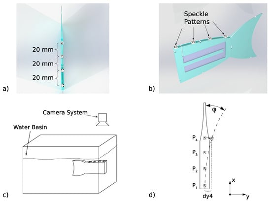
Figure 5.
Fish fin robot with speckle patterns for deflection measurements using digital image correlation. (a) Top view with distances of the speckle patterns, (b) side view, (c) water basin with the mounted robot under water and camera system above, (d) top view of the fish fin as seen by the camera.
The DEAs were activated with a voltage of 3000 V with a square-waveform at different switching frequencies between 0.6 Hz and 1 Hz. The camera recorded the robot’s movement and the positions of the speckle patterns in each video frame. For the measurement, the robot was clamped at the front side of the water basin and held in an upright position as depicted in Figure 5c,d. The camera system itself was held above the water basin with the prepared robot under water. By recording the images from above the setup it was possible to record the x- and y-position values of each of the speckles and to calculate the deflections afterwards. For that, the lower fixed speckle pattern was used as the reference pattern since it was clamped and not moving with the bending motion. The deflections in the y-direction were then calculated by forming the three displacement differences in relation to the y position of speckle P1,
3. Results and Discussion
We demonstrated a fully functional fish fin robot that utilizes a conductive hydrogel as highly conductive and very elastic electrode material. A total of two fish fins were built and investigated. The setup performs a bending motion under water with three stable bending states and performs as expected. In the following the results are discussed in detail.
3.1. Hydrogel Characteristics: Mechanical
To characterize the compliance of the hydrogel material, mechanical measurements were carried out. Three different samples were tested until fracture to evaluate the mechanical compliance of the material. Figure 6 shows the results of the mechanical measurements for the stretching until break and a zoom in the relevant stretch range between a ratio of 1 and 2.
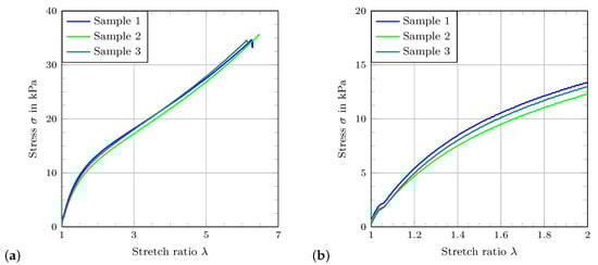
Figure 6.
Stress–stretch curves for the tensile tests. (a) Results of the measurement until fracture (b) zoom-in of the stress–stretch curves in the relevant stretch range.
For measurement, the samples are taken out of the moisturizing storage box and measured in one run. Drying effects can occur over the measurement time, explaining the slight offset of the curves. The slight fluctuations in the curves for the measurement until fracture are due to the mechanical mounting in the tensile testing machine and do not reflect any particular features of the material tested. To put the detected elastic properties of the hydrogel in context to the other polymer materials, Figure 7 gives a comparative overview between the stress-stretch properties of the conductive hydrogel, the dielectric material and the matrix material. It can be easily obtained that the used hydrogel is softer by orders of magnitude. The used hydrogel electrodes are also fabricated in smaller dimensions than the matrix material and the structure itself. Therefore, the stretch–stress comparison between the polymer materials can be used to obtain an impression about the compliance influence of the hydrogel on the robotic structure. From this comparison it can be deduced that the mechanical behavior of the overall structure is barely influenced by the hydrogel.
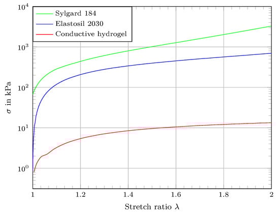
Figure 7.
Comparison of stretch–stress properties between the used polymer materials in logarithmic scale.
3.2. Hydrogel Characteristics: Electrical
Figure 8 shows an illustrative example of the electrochemical characterization of the hydrogel by impedance spectroscopy. The measurement resulted in low-noise, clear and plausible impedance spectra: As shown in Figure 8, the impedance values of the hydrogel are detected in the lower kΩ range within the investigated frequencies. In comparison to established electrode materials based on carbon fillers, showing resistance values in the range of 101 kΩ for electrodes in the size of 5 mm × 30 mm, the detected values are in a comparable order of magnitude [23]. The stable measurement and the detected range of the impedance values indicates that a proper charge transport in the material is given and the hydrogel can be regarded as conductive in terms of the desired application. Conversely, the principle applicability of this measurement method is proven. The phase amounts to ca. −45° what means that a resistive–capacitive behavior is detected. Since the desired application is sufficiently examined by determining the absolute properties of impedance, the method is not supported with equivalent circuit models which is most commonly used to draw more detailed conclusions from the impedance spectrum.
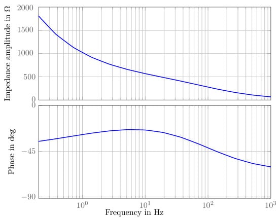
Figure 8.
Bode plot of the impedance amplitude and the phase of the hydrogel as the result of the performed measurement.
The performed measurements showed a wide range of fluctuating results in comparison to each other. The corrupted results could be classified as distorted and sorted out. Due to these fluctuations no clear trend could be derived from the measurement series. The EIS technique using hydrogel samples is influenced by a variety of effects which is why various reasons can be given for the deviations. The most likely reasons are:
- Environmental conditions (temperature, relative humidity);
- Aging effects of the samples (due to storage and measurement duration);
- Chemical reactions with the electrode material.
These effects must be controlled by means of an appropriate stability of the electrode material, a controllable test cell and resulting invariant measurement conditions. A measurement routine for this has been developed and a plausible result could be presented. Despite the lack of stable reproducible results, the order of magnitude of the impedance of the hydrogel is found to be within acceptable ranges for the developed setup. Further work will focus on the reproducibility and the modeling of the measurement results in order to use impedance spectroscopy as an even more meaningful tool for electrochemical characterization of hydrogels.
3.3. Displacement Measurements
To obtain an estimation of the resonance frequency of the system moving under water the detected deflections from the measurement series were processed. The maximum deflections were calculated from the DIC measurements of the movement of the fish fin in water (see Figure 5) for the different switching frequencies. By subtracting the minimum deflection from the maximum deflection of the whole measurement series:
the maximum deflection differences are determined. From these maximum deflection differences a resonance frequency can be directly derived. In the investigated setup the resonance frequency was determined at 0.8 Hz. Figure 9 shows the results of the frequency dependent evaluation.
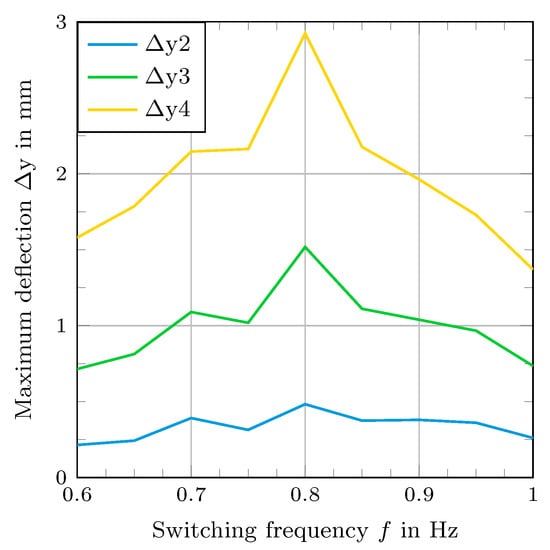
Figure 9.
Comparison of maximum deflection differences for the speckle patterns at P2–P4 from Figure 4 for different switching frequencies at the driving voltage of 3000 V.
Figure 10 gives an insight on the image processing. By detecting the exact positions of the speckle patterns in the initial state and the deformed state of the robot it was possible to calculate the deflections as described.
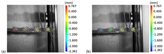
Figure 10.
Recorded images of the DIC measurement together with the detected displacement information in y-direction. (a) Exemplary for the robot near its initial state (b) for a deflected state.
The detailed measurement results of the detected deflections at the mechanical resonant frequency are given in Figure 11. It should be noted that there is a slight unsymmetry of the deflection to the negative y-direction. A possible explanation for that behavior is that the reflecting waves from the walls of the water basin additionally influence the bending motion.
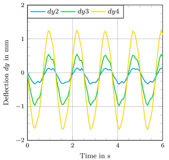
Figure 11.
Time course of the deflection of the fish fin at resonance frequency (0.8 Hz) at the driving voltage of 3000 V.
From that time course we determined the maximum bending deflection of 1.67 mm for the speckle point P4 as an absolute value.
4. Conclusions
The developed concept of a tri-stable bending structure could be validated and categorized as fully functional based on the performed measurements. It was possible to drive a robot underwater without the need for any carbon-based electrodes. The hydrogel-based electrodes showed both sufficient charge transport in the material and high compliance and elasticity, respectively. By utilizing the outstanding properties of the hydrogel in combination with the used anisotropic textile-elastomer composite, an actuator structure is presented that can be used as a possible propulsion element for underwater applications. The developed robotic concept presents an approach for possible enhancements of the electro-mechanical properties of the DEAs and to adjust the robotic concept to aqueous surroundings. The robot reached bending deflections under water of up to 1.67 mm at the end of the electrical activated part. A mechanical resonance frequency of 0.8 Hz for the movement under water could be obtained. The hydrogel-based electrodes performed in the expected manner with sufficient ability to provide the charge separation on the outer sides of the DEAs and highly elastic properties. In that way an underwater movement was possible, completely avoiding carbon-based electrodes for the DEAs.
The results show that the material is sufficiently suitable for a use as EAP electrodes since charge separation is the underlying effect in DEAs. For future developments there are open tasks and relevant aspects of interest. The goal of demonstrating sufficient charge transport ability with the help of the EIS measurement was fulfilled. The performed measurements do not give a definitive insight into whether the charge carriers are moving through the material or if the measured values indicate polarization effects in the form of charge separation. The examination of these effects will be a task for future work. Furthermore, an adaption of the applied voltages for the measurement to a higher range, similar to the use case could be taken into account to investigate additional effects of high voltages on the material. Another possibility for the development of improved performance gels lies in the composition of the conductive hydrogel itself. A specific adjustment of the transport mechanism by changing the charge carriers could lead to enhanced electrical properties and more adaptive tuneability to the desired application.
Author Contributions
Conceptualization, S.P. and A.M.; methodology, S.P., A.M., R.G., K.K. and J.M.; validation, S.P., R.G., A.M. and C.B.; formal analysis, S.P. and G.G.; investigation, A.M., K.K. and S.P.; resources, S.P., A.M. and R.G.; data curation, S.P. and A.M.; writing, original draft preparation, S.P., A.M., R.G. and J.M.; writing, review and editing, C.B., M.Z. and G.G.; visualization, S.P., A.M., R.G. and J.M.; supervision, C.B., M.Z. and G.G.; project administration, S.P. All authors have read and agreed to the published version of the manuscript.
Funding
This research was fully funded by the DFG (German Research Foundation), Project Number 380321452-GRK2430.
Institutional Review Board Statement
Not applicable.
Informed Consent Statement
Not applicable.
Data Availability Statement
Data is available from Authors upon reasonable request.
Acknowledgments
The DFG research project 380321452/GRK 2430 is supported by the Deutsche Forschungsgemeinschaft (DFG, German Research Foundation). The authors gratefully acknowledge the financial support.
Conflicts of Interest
The authors declare no conflict of interest.
Abbreviations
The following abbreviations are used in this manuscript:
| EAP | Electroactive polymer |
| DEA | Dielectric elastomer actuator |
| DE | Dielectric elastomer |
| DIC | Digital image correlation |
| EIS | Electrical impedance spectroscopy |
References
- Cheng, T.; Li, G.; Liang, Y.; Zhang, M.; Liu, B.; Wong, T.W.; Forman, J.; Chen, M.; Wang, G.; Tao, Y.; et al. Untethered soft robotic jellyfish. Smart Mater. Struct. 2018, 28, 015019. [Google Scholar] [CrossRef]
- Berlinger, F.; Duduta, M.; Gloria, H.; Clarke, D.; Nagpal, R.; Wood, R. A modular dielectric elastomer actuator to drive miniature autonomous underwater vehicles. In Proceedings of the 2018 IEEE International Conference on Robotics and Automation (ICRA), Brisbane, QLD, Australia, 21–25 May 2018; pp. 3429–3435. [Google Scholar]
- Anderson, I.A.; Tse, T.C.H.; Inamura, T.; O’Brien, B.; McKay, T.; Gisby, T. Flexidrive: A soft artificial muscle motor. In Electroactive Polymer Actuators and Devices (EAPAD) 2011; International Society for Optics and Photonics: Bellingham, WA, USA, 2011; Volume 7976, p. 79761T. [Google Scholar]
- Yuan, W.; Hu, L.; Yu, Z.; Lam, T.; Biggs, J.; Ha, S.M.; Xi, D.; Chen, B.; Senesky, M.K.; Grüner, G.; et al. Fault-tolerant dielectric elastomer actuators using single-walled carbon nanotube electrodes. Adv. Mater. 2008, 20, 621–625. [Google Scholar] [CrossRef]
- Carpi, F.; Chiarelli, P.; Mazzoldi, A.; De Rossi, D. Electromechanical characterisation of dielectric elastomer planar actuators: Comparative evaluation of different electrode materials and different counterloads. Sens. Actuators A Phys. 2003, 107, 85–95. [Google Scholar] [CrossRef]
- Mishra, S.; Rani, P.; Sen, G.; Dey, K.P. Preparation, properties and application of hydrogels: A review. In Hydrogels; Springer: Singapore, 2018; pp. 145–173. [Google Scholar]
- Liu, X.; Liu, J.; Lin, S.; Zhao, X. Hydrogel machines. Mater. Today 2020, 36, 102–124. [Google Scholar] [CrossRef]
- Lee, C.J.; Wu, H.; Hu, Y.; Young, M.; Wang, H.; Lynch, D.; Xu, F.; Cong, H.; Cheng, G. Ionic conductivity of polyelectrolyte hydrogels. ACS Appl. Mater. Interfaces 2018, 10, 5845–5852. [Google Scholar]
- Keplinger, C.; Sun, J.Y.; Foo, C.C.; Rothemund, P.; Whitesides, G.M.; Suo, Z. Stretchable, transparent, ionic conductors. Science 2013, 341, 984–987. [Google Scholar] [CrossRef] [PubMed] [Green Version]
- Wang, Z.; Cong, Y.; Fu, J. Stretchable and tough conductive hydrogels for flexible pressure and strain sensors. J. Mater. Chem. B 2020, 8, 3437–3459. [Google Scholar] [CrossRef] [PubMed]
- Li, T.; Li, G.; Liang, Y.; Cheng, T.; Dai, J.; Yang, X.; Liu, B.; Zeng, Z.; Huang, Z.; Luo, Y.; et al. Fast-moving soft electronic fish. Sci. Adv. 2017, 3, e1602045. [Google Scholar] [CrossRef] [PubMed] [Green Version]
- Katzschmann, R.K.; DelPreto, J.; MacCurdy, R.; Rus, D. Exploration of underwater life with an acoustically controlled soft robotic fish. Sci. Robot. 2018, 3, 16. [Google Scholar] [CrossRef] [PubMed] [Green Version]
- Joshi, A.; Kulkarni, A.; Tadesse, Y. FludoJelly: Experimental study on jellyfish-like soft robot enabled by soft pneumatic composite (SPC). Robotics 2019, 8, 56. [Google Scholar] [CrossRef] [Green Version]
- Ishida, M.; Drotman, D.; Shih, B.; Hermes, M.; Luhar, M.; Tolley, M.T. Morphing structure for changing hydrodynamic characteristics of a soft underwater walking robot. IEEE Robot. Autom. Lett. 2019, 4, 4163–4169. [Google Scholar] [CrossRef]
- Wehner, M.; Truby, R.L.; Fitzgerald, D.J.; Mosadegh, B.; Whitesides, G.M.; Lewis, J.A.; Wood, R.J. An integrated design and fabrication strategy for entirely soft, autonomous robots. Nature 2016, 536, 451–455. [Google Scholar] [CrossRef] [PubMed]
- Frame, J.; Lopez, N.; Curet, O.; Engeberg, E.D. Thrust force characterization of free-swimming soft robotic jellyfish. Bioinspir. Biomim. 2018, 13, 064001. [Google Scholar] [CrossRef] [PubMed]
- Shintake, J.; Schubert, B.; Rosset, S.; Shea, H.; Floreano, D. Variable stiffness actuator for soft robotics using dielectric elastomer and low-melting-point alloy. In Proceedings of the 2015 IEEE/RSJ International Conference on Intelligent Robots and Systems (IROS), Hamburg, Germany, 28 September–2 October 2015; pp. 1097–1102. [Google Scholar]
- Christianson, C.; Goldberg, N.N.; Deheyn, D.D.; Cai, S.; Tolley, M.T. Translucent soft robots driven by frameless fluid electrode dielectric elastomer actuators. Sci. Robot. 2018, 3, 17. [Google Scholar] [CrossRef] [PubMed] [Green Version]
- Xu, C.; Li, B.; Xu, C.; Zheng, J. A novel dielectric elastomer actuator based on compliant polyvinyl alcohol hydrogel electrodes. J. Mater. Sci. Mater. Electron. 2015, 26, 9213–9218. [Google Scholar] [CrossRef]
- Gao, Y.; Fang, X.; Tran, D.; Ju, K.; Qian, B.; Li, J. Dielectric elastomer actuators based on stretchable and self-healable hydrogel electrodes. R. Soc. Open Sci. 2019, 6, 182145. [Google Scholar] [CrossRef] [PubMed] [Green Version]
- Low, K.; Chong, C. Parametric study of the swimming performance of a fish robot propelled by a flexible caudal fin. Bioinspir. Biomim. 2010, 5, 046002. [Google Scholar] [CrossRef] [PubMed]
- Jusufi, A.; Vogt, D.M.; Wood, R.J.; Lauder, G.V. Undulatory swimming performance and body stiffness modulation in a soft robotic fish-inspired physical model. Soft Robot. 2017, 4, 202–210. [Google Scholar] [CrossRef] [PubMed] [Green Version]
- Schlatter, S.; Rosset, S.; Shea, H. Inkjet printing of carbon black electrodes for dielectric elastomer actuators. In Electroactive Polymer Actuators and Devices (EAPAD) 2017; International Society for Optics and Photonics: Bellingham, WA, USA, 2017; Volume 10163, p. 1016311. [Google Scholar]
Publisher’s Note: MDPI stays neutral with regard to jurisdictional claims in published maps and institutional affiliations. |
© 2021 by the authors. Licensee MDPI, Basel, Switzerland. This article is an open access article distributed under the terms and conditions of the Creative Commons Attribution (CC BY) license (https://creativecommons.org/licenses/by/4.0/).