Article

Five-Fingered Passive Force Feedback Glove Using a Variable Ratio Lever Mechanism †

1
State Key Lab of Virtual Reality Technology and Systems, Beihang University, No. 37 Xueyuan Road, Haidian District, Beijing 100191, China
2
Beijing Advanced Innovation Center for Biomedical Engineering, Beihang University, No. 37 Xueyuan Road, Haidian District, Beijing 100191, China
3
Department of Mechanical Engineering, University of Auckland, Auckland 1142, New Zealand
4
Peng Cheng Laboratory, Shenzhen 518052, China
*
Author to whom correspondence should be addressed.
This paper is an extended version of the conference paper “Achieving High Stiffness Range of Force Feedback Gloves using Variable Stiffness Mechanism” Presented at the 2019 IEEE World Haptics Conference (WHC) in Tokyo, Japan, 9–12 July 2019.
Actuators 2021, 10(5), 96; https://doi.org/10.3390/act10050096
Submission received: 26 March 2021 / Revised: 21 April 2021 / Accepted: 30 April 2021 / Published: 1 May 2021
(This article belongs to the Section Actuators for Robotics)

Abstract

:
Force feedback gloves allow users to touch and manipulate virtual objects intuitively. Compared with gloves providing active feedback force, gloves with passive feedback force are promising in terms of safety and low weight, but simulating the variable stiffness of virtual objects is more challenging. Addressing this difficulty, we propose a five-fingered glove with passive force feedback employing a variable ratio lever mechanism. The stiffness of the proposed glove is tuned by changing the structural stiffness of this mechanism rather than by applying torque control at each joint of the finger. The switch between free and constrained space is realized in real time by locking/unlocking the revolute joints of the glove using a servo motor. Furthermore, a predictive control mode is proposed to reduce the response time of the control system, and the actual response time is less than the limit of the delay (45 ms) that humans can perceive between visual and haptic stimuli. Experimental results show that the linear stiffness at the fingertip ranges from 0.89 to 619.89 N/m, and the maximum backdrive force of the proposed glove is less than 0.147 N.

1. Introduction

Wearable haptic devices that support diverse hand postures and provide users with natural interaction experiences have greater potential in various applications than traditional desktop haptic interfaces. Force feedback gloves, a typical example of wearable haptic devices, allow users to touch and intuitively manipulate (such as grasping, pinching, and lifting) remote or virtual objects, dramatically enhancing the immersion of the haptic experience. Given these advantages, force feedback gloves have attracted increasing attention from researchers and start-up companies, and are widely explored for virtual reality applications such as mechanical assembly, teleoperation, and virtual games.
Basing on the reviews [1,2], the characteristics of desirable force feedback gloves are as follows: first, the gloves should be capable of simulating virtual objects of different stiffness with fast dynamic response; second, the gloves must be safe and lightweight, and the tradeoff between backdrivability and maximum force/torque requires careful design to meet the requirements for both free space and constrained space; third, the gloves should be capable of simulating the cooperative operation of five fingers without mechanical interference, as well as providing a large workspace that allows users to fully clench their fists and extend/swing their fingers. Nevertheless, it is extremely challenging to develop a glove with such competitive characteristics.
The past three decades have seen the development of many force feedback gloves. On the basis of the actuation principle, force feedback gloves can be generally classified into three categories: gloves with pneumatic and/or hydraulic actuators [3], gloves with electric motors [4], and gloves with actuators that use functional materials [5,6]. Among these, force feedback gloves driven by electric motors, classified as active and passive [2], are widely favored because of their fast dynamic response, high precision control, and portability.
As defined in [2], active gloves can provide not only passive force but also active force or motion, and the active force generated by actuators is directly applied to the user’s hands through the transmission system. Passive gloves can only provide a passive force generated by a brake, controllable damper, or clutch. In the following section, we will mainly focus on electric-driven gloves and, for details on other actuation-based gloves, refer to [2].
CyberGrasp [7], which weighs 450 g, is an example of a force feedback glove driven by electric motors that provide active feedback force by using motor-driven cables. With a 180 g exoskeleton mounted on the back of the hand, the RML glove [8] provides haptic force feedback to each finger by using a single actuator unit and a uniquely designed push–pull cable mechanism. Jo and Bae [9] developed a force feedback glove, which integrated the linkage structure and force-controllable actuator module to apply the feedback force to the fingertip. A haptic hand exoskeleton with cable modules was realized by the PERCRO (Laboratory of the Scuola Superiore Sant’Anna, Pisa, Italy), which used three motors to change the direction and magnitude of the force applied on each finger [10]. These gloves can provide active force and simulate virtual objects of different stiffnesses. However, their transmission systems tend to be bulky, increasing the complexity of the device. Worse yet, as the active force generated by the motors is transmitted directly to the fingers, safety may be compromised if the motors fail.
Compared with active gloves, passive gloves have greater advantages of light weight, safety, and simple structure. Wolverine [11], a well-known haptic glove employing the brake mechanism, can provide a passive feedback force up to 106 N, with a total weight of about 55 g. Dexmo [12], which provides binary haptic feedback, produces passive feedback force by driving two stopping sliders and locking the ratchet wheel firmly in place. The aforementioned passive solutions not only reduce weight but also are inherently safe, however, they cannot simulate virtual objects with variable stiffness.
In our previous work [13], to realize the simulation of variable stiffness while ensuring user safety and light weight, we introduced a variable stiffness mechanism into the passive solution and developed a single-fingered force feedback glove with variable stiffness (named the SFVS glove). Compared with the existing passive gloves, the SFVS glove can simulate virtual objects of different stiffnesses, while further studies should be explored to simulate the cooperative operation of five fingers for natural interaction. In addition, the desirable minimum stiffness is zero, whereas the minimum simulated stiffness of the SFVS glove is higher than 130 Nmm/rad (the stiffness in this paper is defined as the ratio of the torque to the rotation angle). Furthermore, the weight of the SFVS glove needs to be further reduced to improve its wearability. Finally, the actual response time of the SFVS glove is higher than 45 ms, exceeding the limit of the perceivable delay between visual and haptic stimuli [14,15].
In this work, we developed a novel five-fingered force feedback glove with variable stiffness (named the FFVS glove). We substantially extended our previous work in terms of dexterity, stiffness range, weight, and response time. Compared with the SFVS glove [13], the FFVS glove not only can achieve the cooperative operation of five fingers with a fast dynamic response, but also has a wider adjustable stiffness range and lighter weight for each finger. We discuss the performance of the FFVS glove in light of quantitative experiments.

2. Variable Stiffness Mechanism

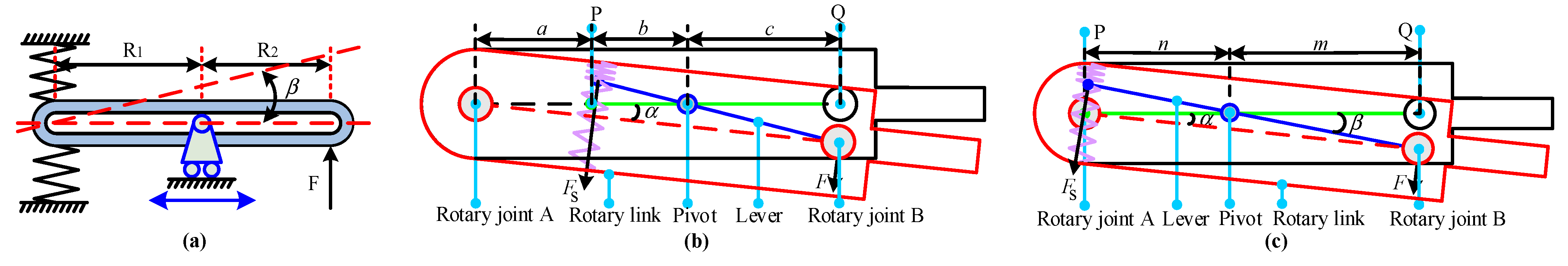
2.1. Principle of Variable Stiffness

Different from devices employing a constant stiffness mechanism, variable stiffness devices typically use elastic components to realize stiffness variation. According to the mechanical structure, variable stiffness mechanisms can generally be classified into five categories [16]: triangle mechanism [17], four-bar mechanism [18], lever mechanism [19,20], special surface mechanism [21], and S-shaped rotating mechanism [22]. Among them, the lever mechanism is widely used because of its advantages in terms of adjustable stiffness range, spatial layout of the device, and motion range.
There are three critical factors for variable stiffness mechanisms based on a lever, namely, the point of action of the external force, the position of the connection of the springs, and the pivot location [23]. As shown in Figure 1a, in the design of the variable stiffness mechanism with a movable pivot, the location of both the external force and the springs is kept constant, whereas the location of the pivot can be tuned. F denotes the external force, and R1 and R2 denote the distance from the pivot position to the points at which the springs connect and the force acts, respectively.
According to the principle described in [23], the rotation angle of the lever ( β ) and the spring constant are constant. The stiffness of the mechanism can be tuned by changing the location of the pivot. Additionally, the stiffness range of the mechanism is dependent on the ratio between R1 and R2, and it is independent of the lever length and the spring constant. The stiffness can be derived as the following equation:
k = T / β = 2 k s ( R 1 / R 2 ) 2 ( R 1 + R 2 ) 2 cos β
where k and ks denote the stiffness of the lever mechanism and the spring constant, respectively; T and β are the equivalent torque and the deflection angle under the external force F, respectively.

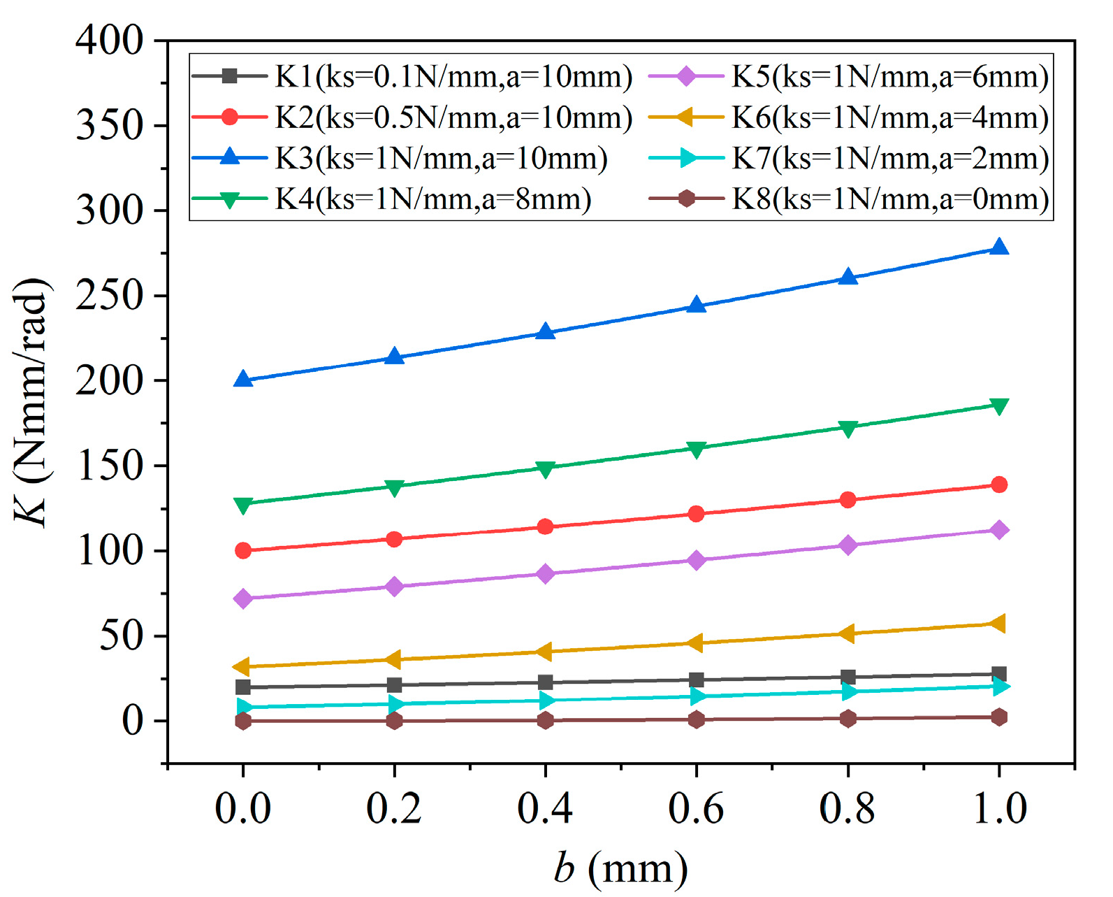
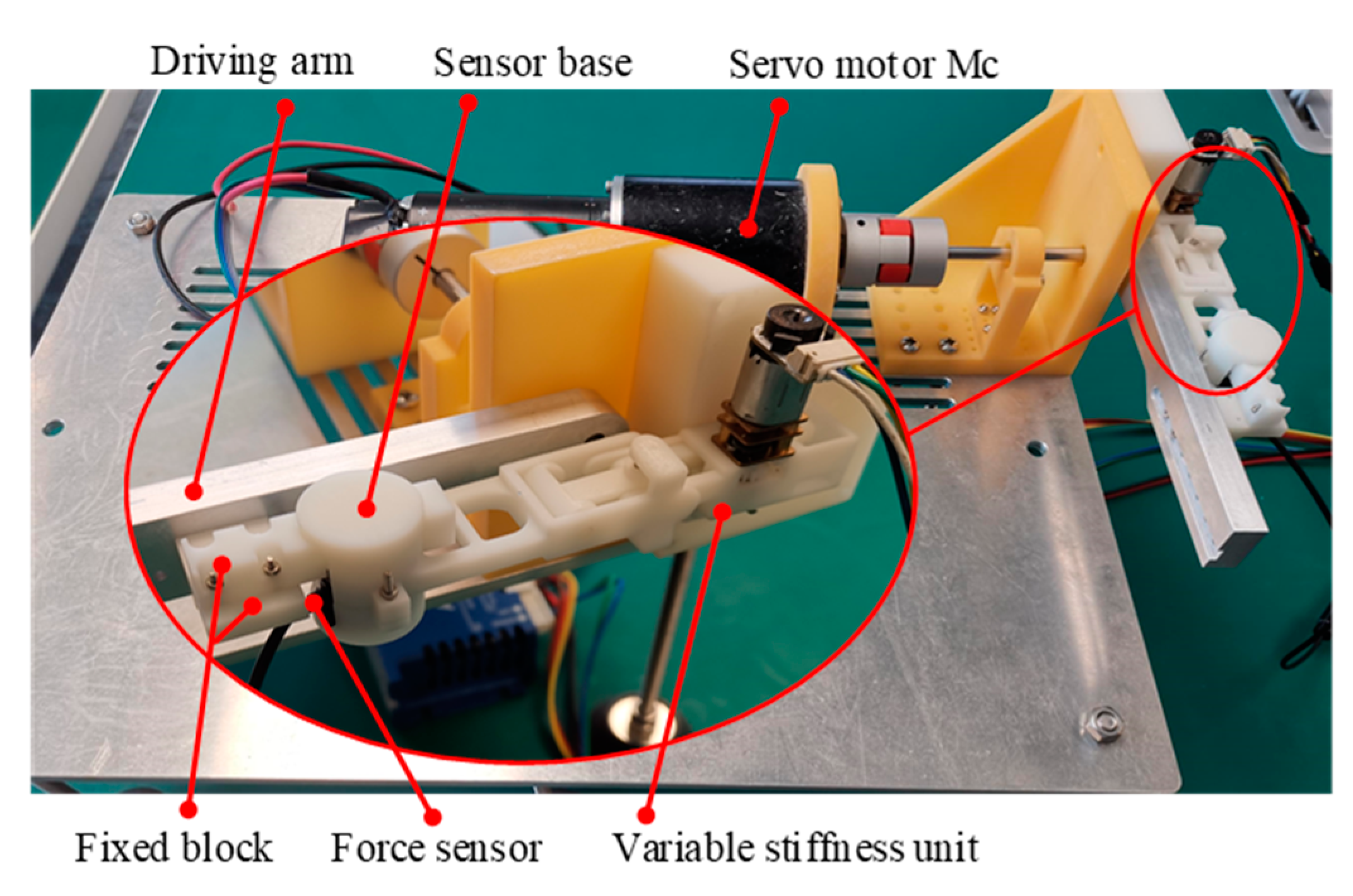
2.2. Design of Variable Stiffness Unit

In our previous work [13], we developed the SFVS glove with variable stiffness by designing a variable stiffness unit. In this work, based on this variable stiffness unit, we optimize the connection positions of the fixed link and the rotary link, further widening the adjustable stiffness range of our FFVS glove. Figure 1b, c depict the variable stiffness units of the SFVS glove and the FFVS glove, respectively.
In the SFVS glove, when the pivot is at point Q, the parameter c approaches zero, and the theoretical stiffness K of the variable stiffness unit is infinity. As the pivot moves from point Q to point P, b decreases and c increases, resulting in a decrease in stiffness K . When the pivot is at point P, the parameter b is zero and the theoretical stiffness K of the variable stiffness unit decreases to minimum ( K = 2 k s a 2 ). Therefore, the minimum stiffness of the variable stiffness unit depends on the parameter a and spring constant k s .
As shown in Figure 2, we quantitatively analyze the effect of the factors above on the stiffness of the variable stiffness unit. When parameter a is 10 mm, the stiffness K increases with the increase in spring constant k s . When the spring constant k s is constant, the stiffness K decreases with the decrease in parameter a . To obtain the minimum stiffness, the parameter a should be zero. Based on the above analysis, we optimize the connection positions of the fixed link and the rotary link in our five-fingered glove (i.e., the length of distance n), further widening the adjustable stiffness range of our five-fingered glove. The theoretical minimum stiffness of the current prototype in this manuscript is zero. In the following, we will further illustrate the effectiveness of optimizing the variable stiffness unit to enlarge the stiffness range through theoretical analysis.
As shown in Figure 1c, when the rotation angle of the rotary link is α , the lever rotates from its initial position (green line) of a certain angle β (blue line). We assume that the springs only deform along the axial direction during the deformation process, and there is no radial shear deformation. Therefore, the force F S generated by the springs is
F s = k s ( Δ + x ) k s ( Δ x ) = 2 k s x
where k s denotes the spring constant; Δ is the pre-deformation of the spring, which is half of the maximum deformation; and x denotes the deformation of the spring. Assuming that the distance from the pivot to point P is n , thus, x can be written as
x = n sin β
Since two symmetrically arranged springs are connected on one side to the lever and on the other side to the rotary link, the force F applied to the lever by the rotary link can be derived as
F = F s n / m
where m denotes the distance from the pivot to point Q. Under the action of F , the resultant torque applied to the rotary link can be written as
T = F ( n + m )
From the geometric relationship in Figure 1c, the relationship between α and β can be obtained as
m sin β = ( n + m ) s i n α
Thus, the stiffness of the mechanism can be formulated as
K = T / α = 2 k s cos α ( m + n ) 2 n 2 / m 2
At the equilibrium position, the stiffness can be expressed as
K = T / α = 2 k s ( m + n ) 2 n 2 / m 2
According to Figure 1c and Figure 8, the point of action of force F corresponds with the pivot position when the pivot is at point Q. In this case, the parameter m and angle α approach zero, and the theoretical stiffness K of the variable stiffness unit is infinity. As the pivot moves from point Q to point P, n decreases and m increases, resulting in a decrease in stiffness K . When the pivot is at point P (i.e., the pivot is coaxial with rotary joint A), the parameter n and the theoretical stiffness K of the variable stiffness unit decrease to zero. Hence, the minimum stiffness of the variable stiffness unit of the proposed FFVS glove is significantly lower than that of the SFVS glove.
The mechanical realization of the variable stiffness unit of our FFVS glove is shown in Figure 3. A servo motor M1 is rigidly attached to the fixed link and drives the translational link through a gear. The other end of the translational link is the pivot, which is connected to the lever. When the servo motor M1 runs, the pivot position changes as the translational link moves. The fixed link, lever, and rotary link form two revolute joints A and B. The rotation angle of the rotary link is constrained in the range of ±45° by the limiting mechanism of the variable stiffness unit.
In addition, we investigate the variation of the maximum rotation angle of the rotary link with the location of the pivot. As shown in Figure 4, the maximum rotation angle of the rotary link is constrained to be 0.785 rad (45°) when the distance between point P and the pivot is less than 1.5 mm. As the distance between point P and the pivot increases, the maximum rotation angle decreases. When the pivot moves to point Q, the variable stiffness unit forms a rigid body and the rotation angle becomes zero.

3. Design of Five-Fingered Force Feedback Glove

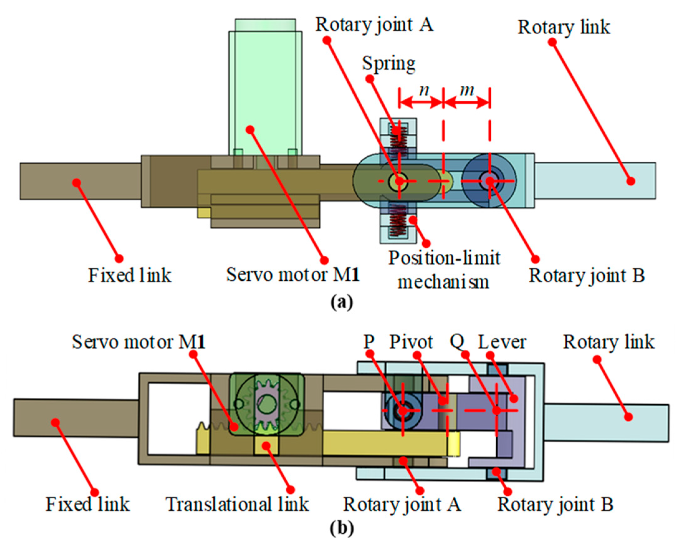
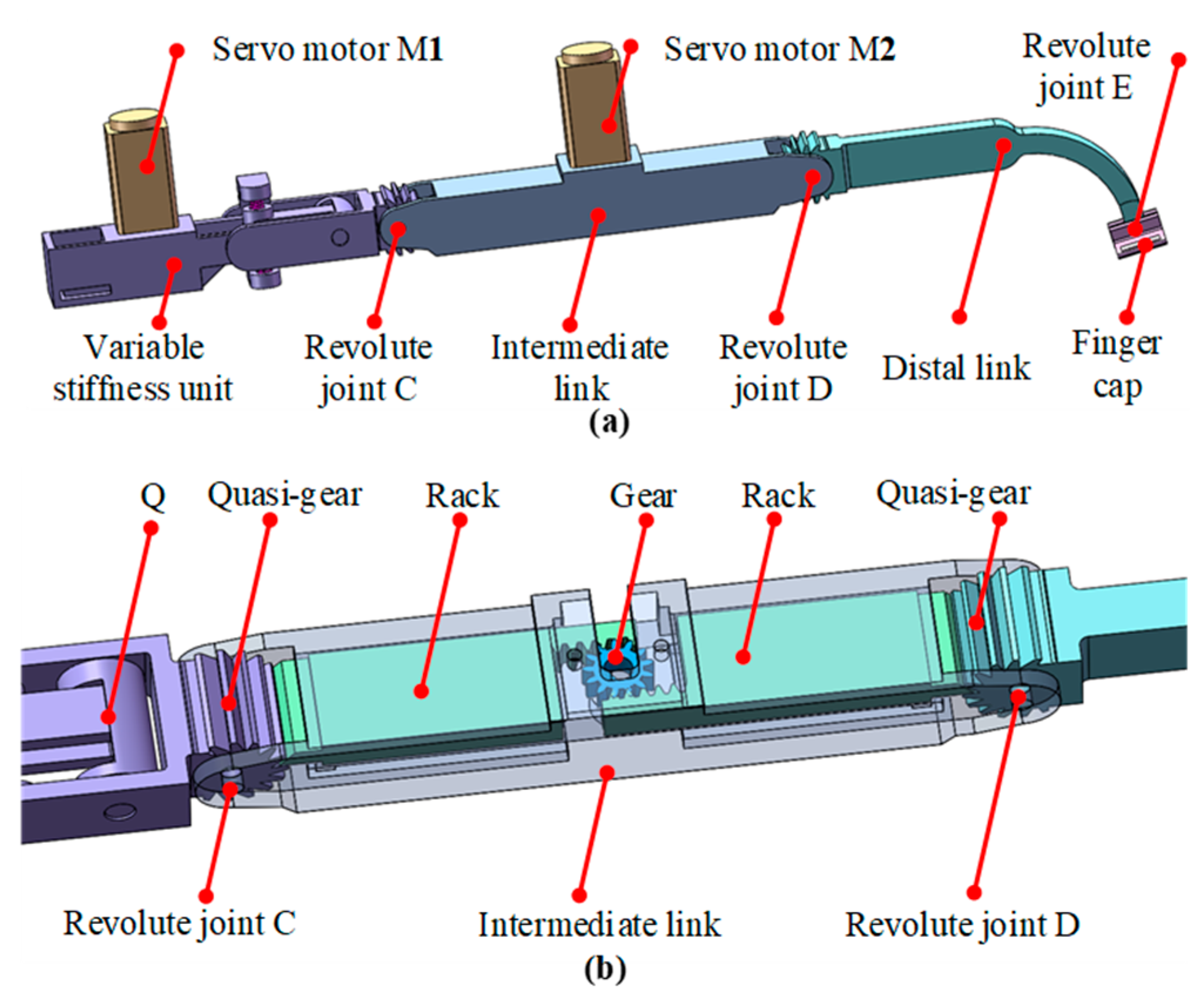
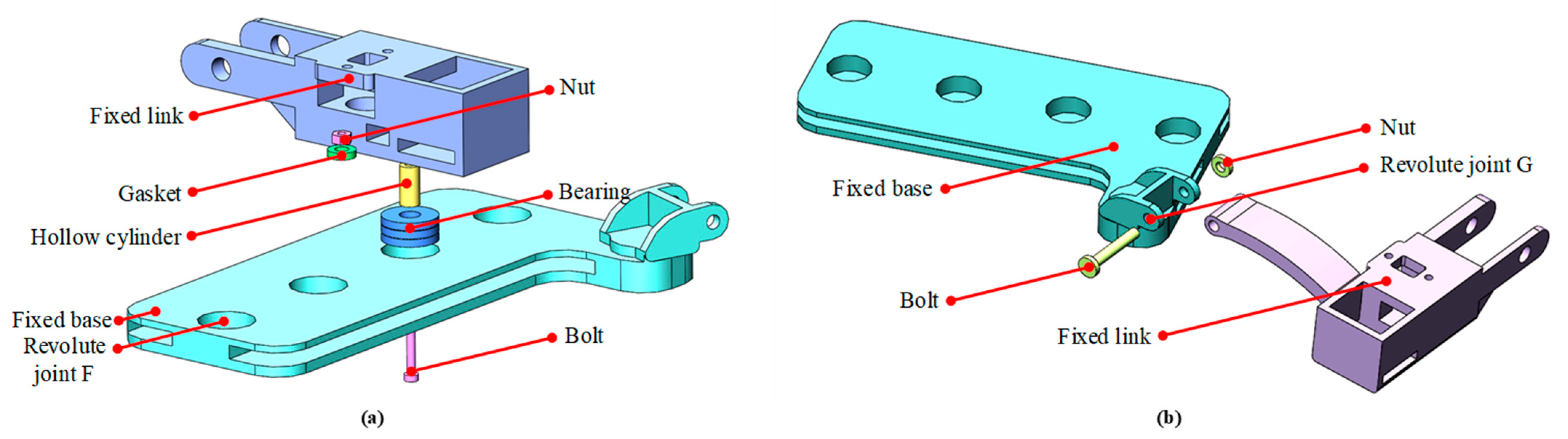
3.1. Mechanical Design of Single Finger

In the FFVS glove, each finger has the same structure. Taking the middle finger as an example, it has three rotary joints, which allow full flexion and full extension. As shown in Figure 5a, the intermediate link connects with the variable stiffness unit and the distal link through revolute joints (C and D). The other end of the distal link transmits the feedback force to the fingertip through the finger cap.
As illustrated in Figure 5b, a locking mechanism is used for the conversion process of the free and constrained space states. When simulating free space, the pivot is at point Q and revolute joints C and D work in the unlocked state, that is, the two joints rotate as the user’s finger bends. While simulating constrained space, the variable stiffness unit is activated when the servo motor M1 drives the translational link to change the location of the pivot and, meanwhile, the servo motor M2 drives two racks to lock the quasi-gears firmly in place. The control mode for simulating the free and constrained spaces is detailed in Section 4.2.
When users grasp a virtual object in the constrained space, the feedback force on the fingertip can be derived as
F f = K α / L
where L is the distance from the rotary joint A to the fingertip, and α is the rotation angle of the rotary link. The linear stiffness at the fingertip can be expressed as
K L = F f / Δ Z = K α cot α / L 2
where Δ Z = L sin α is the movement distance of the fingertip in the vertical direction.

3.2. Iterative Design Analysis

Considering the extensive flat structure on the intermediate and distal links, we performed iterative design analysis on these two links to reduce their weight without compromising the structural strength of our FFVS glove. In the process of iterative design analysis, the minimum strain energy was considered as the objective function. The maximum limit of the nodal displacement (displacement ≤ 1 mm) and the upper limit of the volume fraction for the entire design space (intermediate link: volume ≤ 60%, distal link: volume ≤ 35%) were defined as the constraint conditions. The maximum number of iterations is 50. To ensure that the glove looks more aesthetically pleasing, we also applied the symmetry constraint.
Similar to Section 3.1, we took the middle finger as an example to perform iterative design analysis using the Abaqus Topology Optimization Module (ATOM, SIMULIA, France). In the quantitative measurement experiment, the maximum feedback force of the SFVS glove reaches up to 12 N [13]. Therefore, the experimental load was selected as 12 N, and the corresponding boundary conditions were applied according to the actual situation in the iterative design analysis.
According to the results, we removed the extensive flat structures of the intermediate link and the distal link of our FFVS glove to reduce its weight. Compared with the weight of each component of the SFVS glove, the weight of the intermediate link and the distal link in the FFVS glove decreased by 20.78% and 12.36%, respectively. In addition, the weight of the fixed link is also reduced by 52.14% through the optimization of the structural layout.

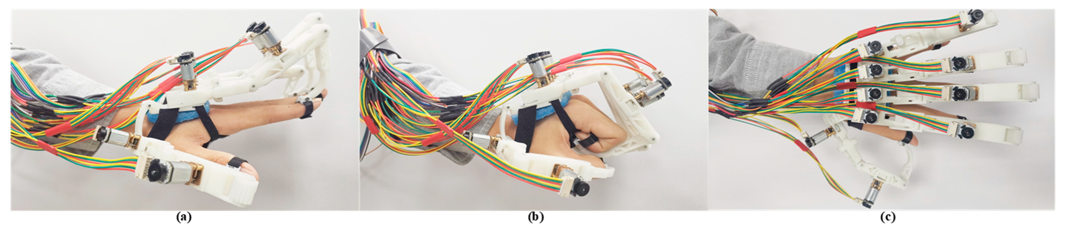
3.3. Physical Prototype of Five-Fingered Force Feedback Glove

The proposed FFVS glove is composed of a fixed base and five fingers. With the exception of the thumb, the connection structures of the other four fingers are identical. Herein, we discuss the middle finger as an example. Figure 6a illustrates the connection mechanism between the fixed link of the variable stiffness unit and the fixed base. The gasket and the hollow cylinder are used to ensure a certain gap between the fixed link and the fixed base. The rotary movement between the fixed link and the fixed base is allowed by the bearing, enabling the ab-adduction of fingers. All the above mentioned components are connected using nuts and bolts. Each finger has four DoFs, including revolute joint C, revolute joint D, revolute joint E, and revolute joint F.
As shown in Figure 6b, the fixed base and the fixed link of the thumb are connected using a nut and bolt, meeting the rotation requirement between the thumb and fixed base. The thumb has four joints (revolute joint C, revolute joint D, revolute joint E, and revolute joint G), allowing four DoFs. As stated above, the total number of DoFs of our FFVS glove is 20, adequate for simulating the grasping and manipulation of virtual objects in daily interactions.
As shown in Figure 7, the finger cap of each finger and the fixed base are, respectively, placed on the dorsal side of the fingertip and the back of the user’s hand. A Velcro band is used to fit different-sized hands, and a foam pad connected to the fixed base further ensures a better fit with the curve of the back of the hands. The motion range of the finger is large enough to achieve ab-adduction and full extension/flexion, adequate to simulate diverse grasping postures. The components of the glove (with the exception of motors) are made of resin and fabricated through 3D printed technology (stereo lithography appearance, SLA). The total weight of the 3D printed components is about 137 g.

4. Control System of Five-Fingered Glove

4.1. Architecture of the Control System

The control system consists of a PC, two low-level controllers (STM32F407ZGT6), servo motor drivers (TB6612FNG), and servo motors. One of the two controllers serves as the primary controller, whereas the other one is the secondary controller. The primary controller communicates with the PC through USART and directly controls the servo motors of thumb, index finger, and middle finger. The other servo motors are controlled by the secondary controller that communicates with the primary controller. When a user grasps or releases a virtual object, the servo motors are controlled to change the states of the locking mechanism and the stiffness of the variable stiffness unit.
The response time is an important metric for quantifying the performance of a force feedback glove. A control system with a low response frequency would significantly reduce the immersion of haptic interaction. In our FFVS glove, the response time of the control system depends on two aspects, the conversion process of the locking mechanism and the regulating process of the variable stiffness unit.
For the locking mechanism, the actual response time of servo motor M2 (SG90, Tiankongrc, Shenzhen, China) used in our previous work [13] is 70 ms. In this paper, we substituted the servo motor M2 with a new servo motor with the same specifications as M1 to improve the response speed of the locking mechanism. After this modification, the variable stiffness unit and the locking mechanism of our FFVS glove use two identical servo motors (GM12-N20K, Shenzhen Chihai Motor Co., Ltd., Shenzhen, China). In our FFVS glove, the response time of the locking mechanism was less than 25 ms, which was measured by an incremental Hall encoder and an STM32 timer (with a temporal resolution of 10 µs).
For the variable stiffness unit, the regulating process depends on the control mode, which determines the maximum movement distance of the pivot, affecting the response time for providing haptic feedback. At present, most virtual interaction systems adopt a simple control method called, in this paper, the direct control mode. The detailed control process of the direct control mode is shown in Figure 8a and Figure 9a. In simulating the grasping motion, when the virtual finger touches the edges of the virtual cube, the pivot is actuated by the servo motor M1 and moves from point Q to the target point. Simultaneously, the working state of the revolute joins C and D transforms from the unlocked state into the locked state. On the contrary, in simulating the releasing motion, when the virtual finger departs from the edges of the virtual cube, the pivot moves to point Q and the two revolute joints unlock. Although the direct control mode has the advantage of a small backdrive force (details in Section 5.2), the response time of the variable stiffness unit exceeds 45 ms when the target point is far from point Q (e.g., when the target is point P, the response time is 75 ms). In the following section, we will describe how to overcome this challenge.

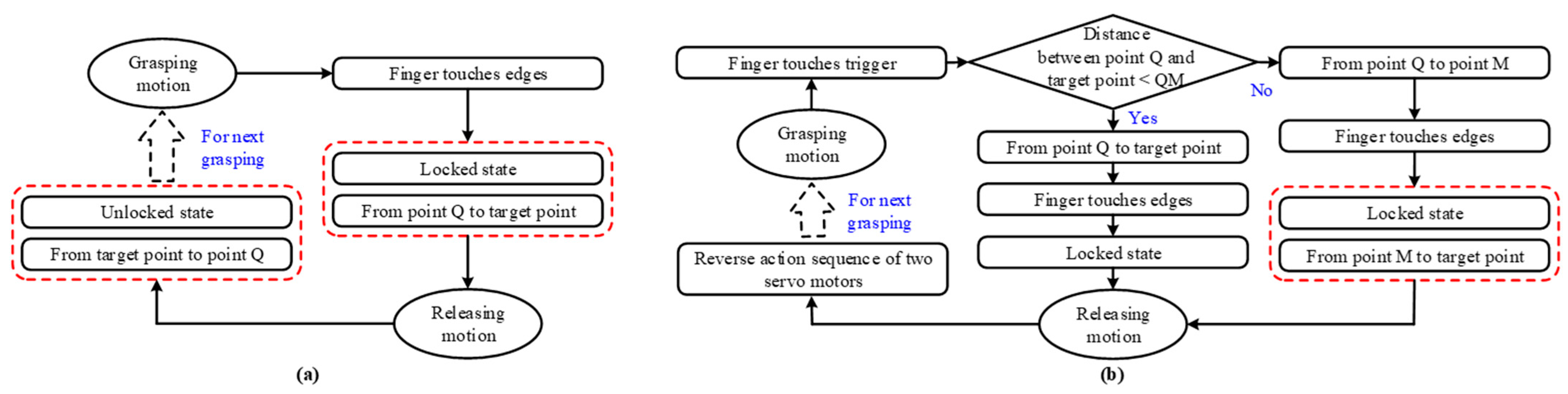
4.2. Predictive Control Mode

One way to reduce the response time of the control system is to regulate the variable stiffness unit in advance. However, early adjustment of the variable stiffness unit will result in the rotation of the rotary link, making the backdrive force greater than that of the direct control mode, and the longer the distance of the early adjustment, the greater the backdrive force. Therefore, in this paper, we propose a predictive control mode for our FFVS glove so as to meet the requirements for both the backdrive force and the response time.
As illustrated in Figure 8b and Figure 9b, we set a trigger boundary. In grasping the virtual objects, when the virtual finger touches the trigger boundary, the servo motor M1 is activated and drives the pivot to start moving. At this time, if the distance between point Q and the target point is shorter than that between points Q and M (we set a reference point M, and the movement of the pivot takes less than 45 ms from point Q to M), the pivot moves to the target point. As the virtual hand moves continuously, the two revolute joints are locked by the servo motor M2 when the virtual finger touches the edges of the virtual cube. On the other side, when the distance between point Q and the target point is longer than that between points Q and M, the control process of the predictive control mode is as follows. First, the pivot moves from point Q to point M when the virtual finger touches the trigger boundary. Subsequently, when the virtual finger touches the edges of the virtual cube, the locking mechanism is activated and, meanwhile, the pivot moves from point M to the target point. In releasing virtual objects, the action sequence of two servo motors is exactly the reverse of that during the grasping phase.

5. Performance Evaluation

In line with the criteria proposed by Salisbury et al. [24], we use the adjustable stiffness range, backdrivability, and maximum feedback force to quantify the performances of the proposed FFVS glove. Herein, we also evaluate the response time, safety, workspace, and fabrication costs of the glove.

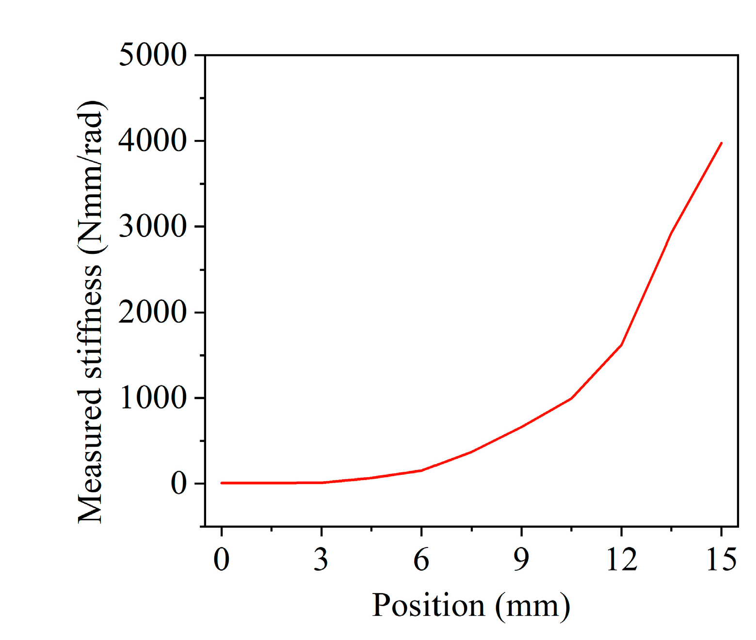
5.1. Performance of Variable Stiffness Unit

To quantitatively evaluate the stiffness performance of the variable stiffness unit, we developed a stiffness measurement device. As shown in Figure 10, the variable stiffness unit is connected to the measurement device, and the force sensor is placed in the sensor base. The torque generated by the servo motor Mc is transmitted to the force sensor through the driving arm, fixed block, and sensor base. To reduce the assembly gap, the rotary link of the variable stiffness unit and the sensor base are integrated into a single component through 3D printing.
During the measurement process, when the pivot moved from point P to point Q, 11 sampling points were selected at equal intervals. The servo motor Mc drove the driving arm to rotate after the pivot had moved to the setting position. The rotation angle and the feedback force were measured using the optical encoder and ATI Nano17 force sensor (ATI Industrial Automation Inc., US), respectively, on the basis of which we obtained the stiffness of the variable stiffness unit (Table 1 and Figure 11)
Experimental results show that the actual stiffness is 7.28 Nmm/rad when the pivot is at point P. The stiffness increases with the increase in the distance between point P and the pivot. When the pivot is at point Q, the theoretical stiffness is infinity. However, due to the elastic modulus of the 3D printed components, the assembly gap caused by the 3D printer machining accuracy, and the shape of the components (mostly slender links), the device slightly deforms, and the maximum stiffness measured by the experiment is 3972.15 Nmm/rad. In the future, we plan to adopt lightweight materials with high elastic modulus (such as carbon fiber or titanium alloy) and precision manufacturing technology, so as to meet the requirements of small deformation, small machining error, and light weight.

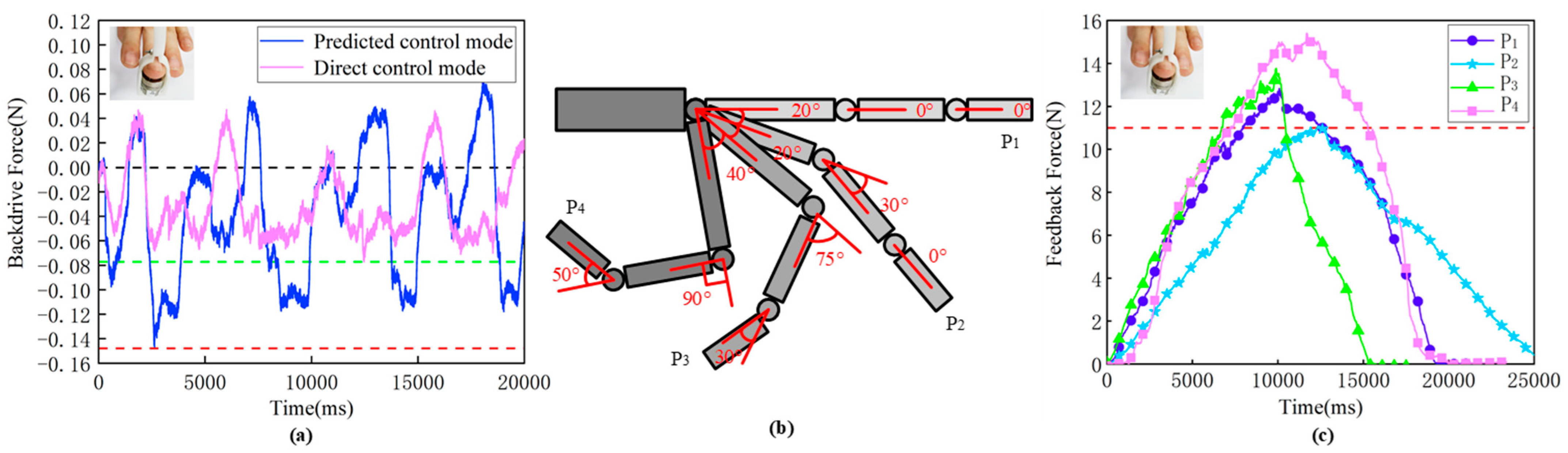
5.2. Performance of Free Space Simulation

For a high-fidelity force feedback glove, the backdrive force should be as small as possible to avoid obstructing the movement of fingers when simulating the free space. We used the same measurement method as in our previous work [13]. As shown in Figure 12a, the fingertip is located on the top of the force sensor, and the fingertip and the force sensor are together placed on a custom-designed finger cap.
The backdrive force of our glove is caused by the friction force at each kinematic joint, the gravity force of each link, and the inertial force of each link. In the experiment, an ATI Nano17 force sensor was used to acquire the backdrive force. The user moved the finger back and forth at near-constant velocity (i.e., each back-and-forth iteration that involved clenching and extending of the fingers took about three to four seconds).
Figure 12a compares the backdrive force between the direct control model and the predictive control mode. We can see that the maximum backdrive force of the direct control mode is no more than 0.08 N when simulating free space (i.e., the pivot was at point Q, and the revolute joints C and D were unlocked). For the predictive control mode, we found that it took less than 45 ms from point Q to the middle point. Therefore, we chose the middle point as point M, described in Section 4. When the pivot was at the middle point and two revolute joints (C and D) were unlocked, the maximum backdrive force of the predictive control mode was about 0.147 N. Although the backdrive force of the predictive control mode is slightly larger than that of the direct control model, it is still small and can meet the requirements of our proposed FFSV glove.

5.3. Performance of Constrained Space Simulation

A force feedback glove should not only be able to simulate the free space but also provide enough feedback force to simulate the constrained space. For our variable stiffness unit, when the pivot is at point Q and revolute joints C and D are locked, the force feedback glove forms a rigid body and its feedback force reaches its maximum.
To evaluate the performance of constrained space simulation, we selected four sampling poses along the trajectory of the middle finger (the length of the middle finger is 95 mm under the extended state), as depicted in Figure 12b. At each sampling pose, the maximum feedback force was measured using the same measurement method and measurement system as our previous work [13]. As shown in Figure 12c, the maximum feedback force exceeds 11 N (red dotted line) at all sampling poses, with the highest being 15.41 N at P4.

5.4. Performance of Other Indicators

For our predictive control mode, the maximum movement distance of the pivot is half the distance between point P and point Q when simulating the grasping motion. We measured the response time of the pivot regulation process (i.e., the response time of the regulating process of the variable stiffness unit) by using an incremental Hall encoder and the STM32 timer (with a temporal resolution of 10 µs). The response time for the maximum movement distance of the pivot was 44 ms, which is less than the limit of the delay (45 ms) a human can perceive between visual and haptic stimuli. Therefore, the actual response time of our FFVS glove can meet the interaction requirements in a virtual experience [14,15].
In our FFVS glove, the servo motors are used to regulate the stiffness of the variable stiffness unit and switch the working state of the locking mechanism, rather than to directly apply torque or force at each finger joint, thus avoiding the risk of injuries when the motors fail. In terms of workspace, our FFVS glove has twenty DoFs, helping to achieve full extension/flexion and ab-adduction. This allows users to manipulate virtual objects using diverse gestures in a natural manner.
In addition, the mechanical structures of our FFVS glove are made of resin material and fabricated through 3D printing at a cost of USD 27.98. The controllers, servo motors, servo motor drivers, wires, bearings, and other parts were purchased for USD 105.73. Therefore, the total cost of our FFVS glove, at about USD 140, is much lower than that of existing commercial force feedback gloves, making it more economical and accessible to consumers.

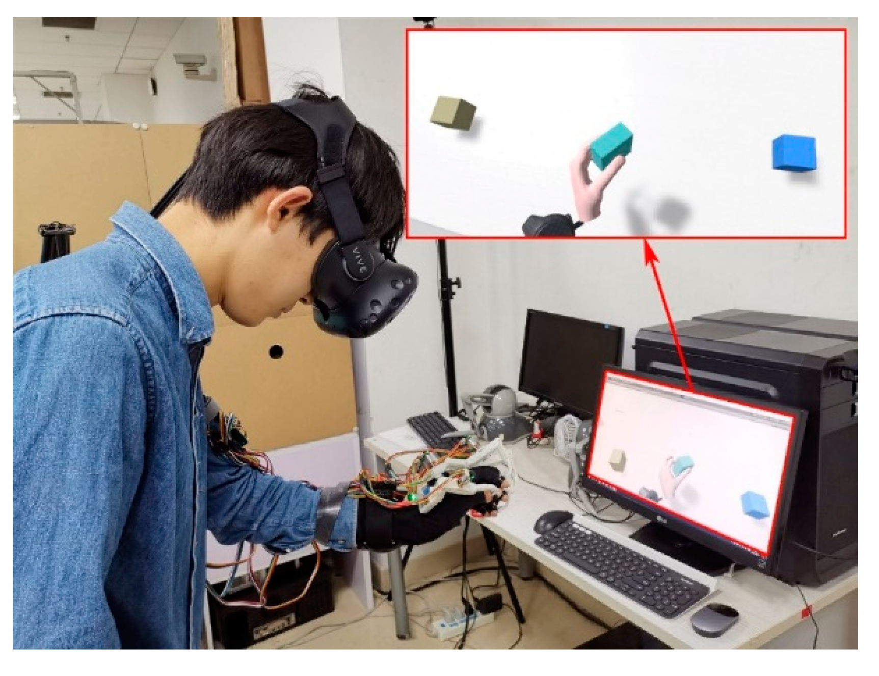
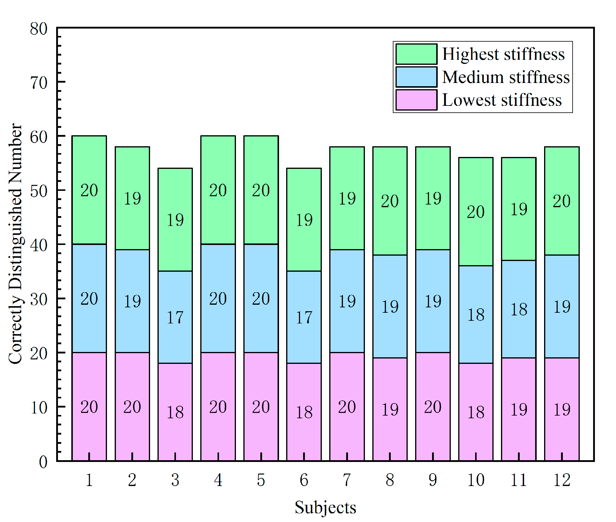
5.5. Exploratory Experiment: Grasping Task

To preliminarily evaluate the effectiveness of the FFVS glove and explore its potential in virtual interaction scenarios, we conducted an exploratory experiment. Twelve participants (six females) recruited from Beihang University took part in the experiments, ranging in age from 20 to 22 years (mean: 21, standard deviation: 0.71). Two of them had previously experienced virtual reality games/systems more than three times, and no participant had any deficiency in stiffness perception ability. All participants signed a written consent form after they had been informed of the objective and procedure of both experiments.
In the training phase, the participants gradually learned how to use our FFVS glove to touch and grasp cubes of various stiffnesses. After 5 min of training, each participant performed 20 trials. In each trial, the participant was allowed to grasp three cubes with the same size and shape but with different colors, as shown in Figure 13. The cubes were randomly assigned one of the following stiffness levels: 68, 370, or 725 Nmm/rad. The different colors of three cubes were only used for easy identification of these cubes and convenient reporting of the experimental results, and there was no corresponding relationship between the color and stiffness. Most importantly, the three cubes with different stiffnesses could achieve the same maximum visual deformation.
Figure 14 presents the data of all trials. The number in each bar segment represents the number of trials in which the participant correctly identified the stiffness level. Green bars, blue bars, and carmine bars represent the highest stiffness, the medium stiffness, and the lowest stiffness, respectively. The average identification accuracy of each stiffness level was higher than 93% for all 12 participants, with 17 being the lowest correct identification number in 20 trials for each stiffness level. These experimental results show that the proposed glove can effectively render objects of different stiffnesses and allow users to distinguish them correctly.

6. Discussion

The quantitative results show that, compared with the SFVS glove [13], the performance of the FFVS glove proposed in this paper is significantly improved in terms of stiffness range, response time, and single-finger weight. Nevertheless, rigorous work needs to be further conducted to improve the performance of the proposed glove.
Firstly, the locking mechanism used for the switching between the free and constrained space states only has two states, unlocked or locked. A simpler mechanism such as a miniature electromagnetic switch can be adopted in the locking mechanism to reduce the number of motors and decrease the complexity of the control system, while maintaining the lightweight structure and fast dynamic response.
Secondly, user evaluation is an effective way to explore the potential of haptic gloves. To fulfill this goal, we plan to integrate motion sensing functions in all rotating joints of our five-fingered glove, and conduct a rigorous perceptual evaluation (such as JND measurement) and some virtual interaction tasks to further evaluate the performance of our glove.

7. Conclusions

In this paper, we present a five-fingered passive force feedback glove employing a variable ratio lever mechanism. By modulating the location of the pivot, our FFVS glove can provide a large range of adjustable stiffness while ensuring a small backdrive force. Through iterative design analysis, the weight of the glove is reduced, and the total weight of the five-fingered prototype is 257 g. In addition, we devise a predictive control mode to improve the response speed of the control system. The motion range of our FFVS glove is large enough to achieve ab-adduction and full extension/flexion without mechanical interference, which significantly enhances the dexterity of the glove and enables users to interact naturally with virtual objects. Furthermore, we quantitatively evaluated the performance of our FFVS glove through objective experiments. In future research, additional haptic modalities such as thermal feedback could be integrated into the glove and the user studies could be carried out to evaluate the performance of the multimodal haptic feedback glove.

Author Contributions

Conceptualization, Y.G.; methodology, Y.G. and D.W.; software, H.W.; validation, X.Y., H.W., and Y.G.; writing—original draft preparation, Y.G.; writing—review and editing, Y.Z., W.X., and D.W.; supervision, D.W. All authors have read and agreed to the published version of the manuscript.

Funding

This work is supported by the National Key Research and Development Program under Grant 2016YFB1001202 and by the National Natural Science Foundation of China under Grant 61532003.

Institutional Review Board Statement

The study was conducted according to the guidelines of the Declaration of Helsinki, and approved by the State Key Laboratory of Virtual Reality Technology and Systems of China.

Informed Consent Statement

Informed consent was obtained from all subjects involved in the study.

Data Availability Statement

Not applicable.

Conflicts of Interest

The authors declare no conflict of interest.

References

  1. Pacchierotti, C.; Sinclair, S.; Solazzi, M.; Frisoli, A.; Hayward, V.; Prattichizzo, D. Wearable haptic systems for the fingertip and the hand: Taxonomy, review, and perspectives. IEEE Trans. Haptics 2017, 10, 580–600. [Google Scholar] [CrossRef] [PubMed] [Green Version]
  2. Wang, D.; Song, M.; Naqash, A.; Zheng, Y.; Xu, W.; Zhang, Y. Toward whole-hand kinesthetic feedback: A survey of force feedback gloves. IEEE Trans. Haptics 2019, 12, 189–204. [Google Scholar] [CrossRef] [PubMed]
  3. Zubrycki, I.; Granosik, G. Novel haptic glove-based interface using jamming principle. In Proceedings of the 2015 10th International Workshop on Robot Motion and Control, Poznan, Poland, 6–8 July 2015; pp. 46–51. [Google Scholar]
  4. Endo, T.; Kawasaki, H.; Mouri, T.; Doi, Y.; Yoshida, T.; Ishigure, Y.; Shimomura, H.; Matsumura, M.; Koketsu, K. Five-fingered haptic interface robot: HIRO III. IEEE Trans. Haptics 2011, 4, 14–27. [Google Scholar] [CrossRef] [PubMed]
  5. Blake, J.; Gurocak, H.B. Haptic glove with MR brakes for virtual reality. IEEE/ASME Trans. Mechatron. 2009, 14, 606–615. [Google Scholar] [CrossRef]
  6. Kuroda, Y.; Shigeta, Y.; Imura, M.; Uranishi, Y.; Oshiro, O. Haptic glove using compression-induced friction torque. In Proceedings of the ASME 2013 Dynamic Systems and Control Conference, Palo Alto, CA, USA, 21–23 October 2013; p. V002T26A004. [Google Scholar]
  7. CyberGlove Systems. Cybergrasp. 2013. Available online: http://www.cyberglovesystems.com/ (accessed on 26 March 2021).
  8. Zhou, M.A.; Ben-Tzvi, P. RML glove—An exoskeleton glove mechanism with haptics feedback. IEEE/ASME Trans. Mechatron. 2015, 20, 641–652. [Google Scholar]
  9. Jo, I.; Bae, J. Design and control of a wearable hand exoskeleton with force-controllable and compact actuator modules. In Proceedings of the 2015 IEEE International Conference on Robotics and Automation, Seattle, WA, USA, 26–30 May 2015; pp. 5596–5601. [Google Scholar]
  10. Fontana, M.; Dettori, A.; Salsedo, F.; Bergamasco, M. Mechanical design of a novel hand exoskeleton for accurate force displaying. In Proceedings of the 2009 IEEE International Conference on Robotics and Automation, Kobe, Japan, 12–17 May 2009; pp. 1704–1709. [Google Scholar]
  11. Choi, I.; Hawkes, E.W.; Christensen, D.L.; Ploch, C.J.; Follmer, S. Wolverine: A wearable haptic interface for grasping in virtual reality. In Proceedings of the 2016 IEEE/RSJ International Conference on Intelligent Robots and Systems, Daejeon, Korea, 9–14 October 2016; pp. 986–993. [Google Scholar]
  12. Gu, X.; Zhang, Y.; Sun, W.; Bian, Y.; Zhou, D.; Kristensson, P.O. Dexmo: An inexpensive and lightweight mechanical exoskeleton for motion capture and force feedback in VR. In Proceedings of the 2016 CHI Conference on Human Factors in Computing Systems, San Jose, CA, USA, 7–12 May 2016; pp. 1991–1995. [Google Scholar]
  13. Guo, Y.; Wang, D.; Wang, Z.; Yang, X.; Wang, H.; Zhang, Y.; Xu, W. Achieving high stiffness range of force feedback gloves using variable stiffness mechanism. In Proceedings of the 2019 IEEE World Haptics Conference, Tokyo, Japan, 9–12 July 2019; pp. 205–210. [Google Scholar]
  14. Vogels, I.M.L.C. Detection of temporal delays in visual-haptic interfaces. Hum. Factors 2004, 46, 118–134. [Google Scholar] [CrossRef] [PubMed]
  15. Doxon, A.J.; Johnson, D.E.; Tan, H.Z.; Provancher, W.R. Human detection and discrimination of tactile repeatability, mechanical backlash, and temporal delay in a combined tactile-kinesthetic haptic display system. IEEE Trans. Haptics 2013, 6, 453–463. [Google Scholar] [CrossRef] [PubMed]
  16. Wang, Y.; Fang, L. Principle and design of mechanically musculoskeletal variable-stiffness mechanism. Robot 2015, 37, 506–512. [Google Scholar]
  17. Van Ham, R.; Vanderborght, B.; Van Damme, M.; Verrelst, B.; Lefeber, D. MACCEPA, the mechanically adjustable compliance and controllable equilibrium position actuator: Design and implementation in a biped robot. Robot. Auton. Syst. 2007, 55, 761–768. [Google Scholar] [CrossRef]
  18. Huang, T.; Huang, H.; Kuan, J. Mechanism and control of continuous-state coupled elastic actuation. J. Intell. Robot. Syst. 2014, 74, 571–587. [Google Scholar] [CrossRef] [Green Version]
  19. Groothuis, S.S.; Rusticelli, G.; Zucchelli, A.; Stramigioli, S.; Carloni, R. The variable stiffness actuator vsaut-ii: Mechanical design, modeling, and identification. IEEE/ASME Trans. Mechatron. 2014, 19, 589–597. [Google Scholar] [CrossRef]
  20. Tsagarakis, N.G.; Sardellitti, I.; Caldwell, D.G. A new variable stiffness actuator (CompAct-VSA): Design and modelling. In Proceedings of the 2011 IEEE/RSJ International Conference on Intelligent Robots and Systems, San Francisco, CA, USA, 25–30 September 2011; pp. 378–383. [Google Scholar]
  21. Vanderborght, B.; Tsagarakis, N.G.; Van Ham, R.; Thorson, I.; Caldwell, D.G. MACCEPA 2.0: Compliant actuator used for energy efficient hopping robot Chobino1D. Auton. Robot. 2011, 31, 55–65. [Google Scholar] [CrossRef]
  22. Masahiko, O.; Nobuyuki, I.; Yuto, N.; Masayuki, I. Stiffness readout in musculo-skeletal humanoid robot by using rotary potentiometer. In Proceedings of the SENSORS, 2010 IEEE, Waikoloa, HI, USA, 1–4 November 2010; pp. 2329–2333. [Google Scholar]
  23. Jafari, A.; Tsagarakis, N.G.; Caldwell, D.G. AwAS-II: A new actuator with adjustable stiffness based on the novel principle of adaptable pivot point and variable lever ratio. In Proceedings of the 2011 IEEE International Conference on Robotics and Automation, Shanghai, China, 9–13 May 2011; pp. 4638–4643. [Google Scholar]
  24. Salisbury, K.; Brock, D.; Massie, T.; Swarup, N.; Zilles, C. Haptic rendering: Programming touch interaction with virtual objects. In Proceedings of the 1995 Symposium on Interactive 3D Graphics, Monterey, CA, USA, 9–12 April 1995; pp. 123–130. [Google Scholar]
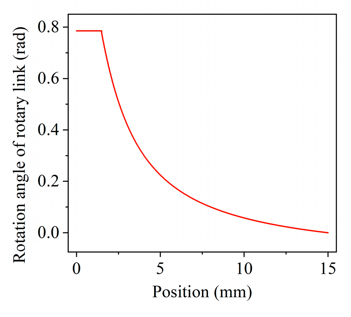
Figure 1. The schematic of the stiffness adjustment principle: (a) Variable stiffness mechanism with a movable pivot (adapted from [16,23]); (b) the stiffness adjustment principle of the SFVS glove; (c) the stiffness adjustment principle of the FFVS glove.
Actuators 10 00096 g001
Figure 2. Effect of spring constant k s and parameter a on stiffness K .
Actuators 10 00096 g002
Figure 3. Virtual prototype of the variable stiffness unit: (a) Front view and (b) top view.
Actuators 10 00096 g003
Figure 4. Maximum rotation angle based on the location of the pivot.
Actuators 10 00096 g004
Figure 5. The virtual prototype in SolidWorks: (a) The overall structure of each finger; (b) the locking mechanism of each finger.
Actuators 10 00096 g005
Figure 6. The connection mechanism between the fixed link and the fingers: (a) The connection structure of the four fingers (no thumb); (b) the connection structure of the thumb.
Actuators 10 00096 g006
Figure 7. Motion states of the glove: (a) Full extension; (b) full flexion; (c) full lateral extension state (maximum abduction).
Actuators 10 00096 g007
Figure 8. The control flow of two different control modes: (a) Direct control mode; (b) predictive control mode.
Actuators 10 00096 g008
Figure 9. The interactive process of two different control modes: (a) Direct control mode; (b) predictive control mode. The red and blue bounding boxes represent the trigger boundary and the edge of the virtual cube.
Actuators 10 00096 g009
Figure 10. The measurement system for stiffness characterization.
Actuators 10 00096 g010
Figure 11. Stiffness of the variable stiffness unit vs. the position of the pivot.
Actuators 10 00096 g011
Figure 12. Performance of free and constrained space simulation: (a) Normal force signals during free space simulation; (b) sampling poses along the trajectory of the middle finger; (c) normal force signals under different sampling poses. The inset figure shows the measurement method of feedback force, and the black, green, and red lines represent 0 N, 0.077 N, and 0.147 N, respectively.
Actuators 10 00096 g012
Figure 13. Exploratory experiment: grasping task.
Actuators 10 00096 g013
Figure 14. Discrimination accuracy of different stiffness cubes during the grasping task.
Actuators 10 00096 g014
Table 1. Stiffness of the variable stiffness unit.
Position (mm)0.01.53.04.56.07.59.010.512.013.515.0
Theoretical stiffness (Nmm/rad)0.005.5628.1382.66200.00450.001012.502450.007200.0036,450.00Infinity
Measured stiffness (Nmm/rad)7.288.8011.8768.16153.70372.42662.08993.131324.172924.213972.15
Linear stiffness (N/m)0.891.091.509.6222.4555.41100.02151.89205.20455.55619.89
Publisher’s Note: MDPI stays neutral with regard to jurisdictional claims in published maps and institutional affiliations.

