Critical Performance Aspects of Retrofitting Apartment Buildings Using a Multifunctional Façade System

Abstract
1. Introduction
2. The Meefs System and Target Buildings
2.1. The Multifunctional Energy Efficient Façade System for Building Retrofitting - The Meefs System
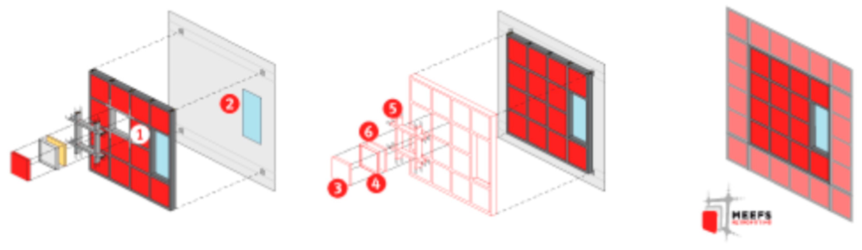
- The structure (Figure 1, 4+5): the Meefs system structure is based on lightweight and cost-effective structural panels and an anchorage system for fixing these structural panels to the existing façade.
- Operating Control System: the façade integrates an intelligent control system for the energy management and control of all the mobile elements. This is integrated in the building energy system.
- Technological modules consisting of structural module and technological units (Figure 1, 3+4+5). All the modules integrated in the façade include a particular technology or flexible combinations of technologies allowing the reduction of primary energy, either by reducing the energy demand of the building or by supplying energy by means of renewable energy sources (RES).
- Back layer insulation: this insulation layer is fixed at the back of each multifunctional panel.
2.2. Critical Issues of the Meefs Systems
2.3. Target Building Stocks
2.3.1. Finnish Apartment Buildings
2.3.2. German Apartment Buildings
2.3.3. Spanish Apartment Buildings
3. Hygrothermal Performance Challenges of Meefs Retrofitting System
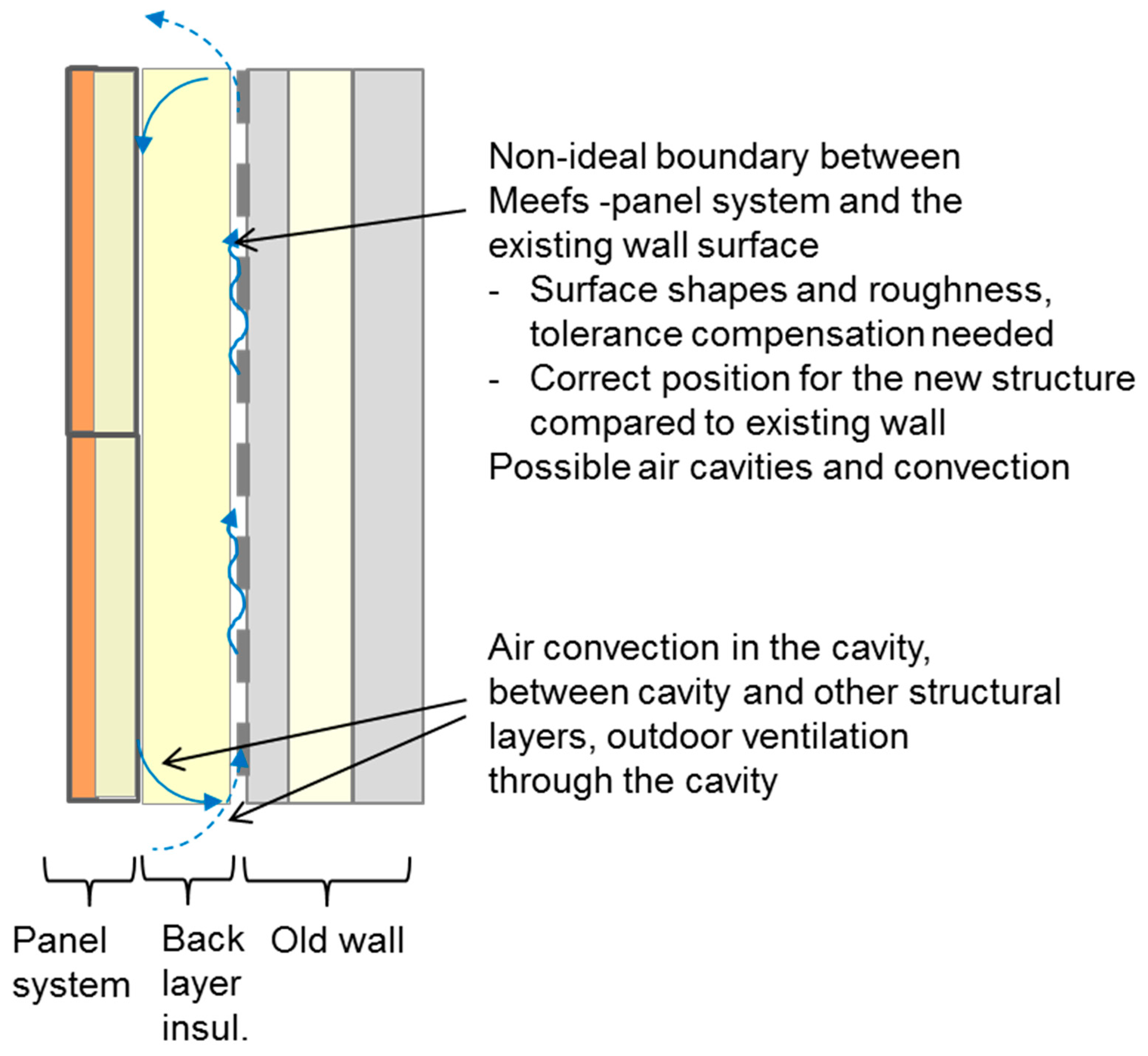
3.1. Thermal Performance - Effect of Non-ideal Contact Conditions and Air Cavities
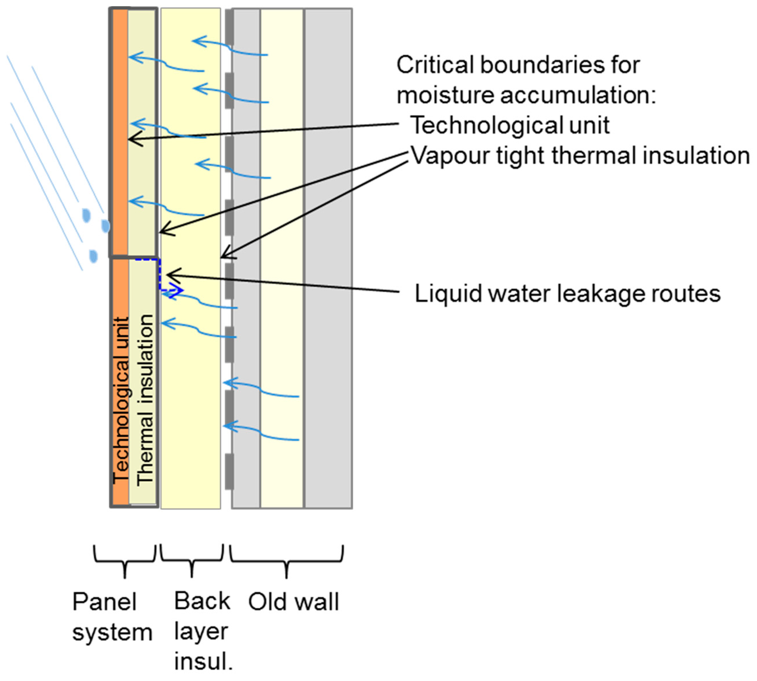
- Load 1) Initial moisture of the material layers, accumulated mainly in the exterior parts of the existing wall (exterior concrete core, brickwork, etc.). Typically, the driving rain is the main reason for the high moisture content.
- Load 2) Moisture flow from indoor air into the structure. This takes place typically by diffusion, and in some cases the air leakages between indoor air space and structural layers can also enhance local moisture transport into the wall.
- Load 3) Possible water leakages through the exterior parts of the wall, typically defects in the structural details or weather protection layers.
3.2. Air Tightness of the Renovated Façade
3.3. Thermal Bridges in the Renovation System
3.4. Moisture Performance Principles
4. Numerical Analysis of the Hygrothermal Performance of Retrofitted Buildings
4.1. Solutions for Safe Moisture Performance of Exterior Renovation Systems
4.1.1. Vapor Open Exterior Layers
4.1.2. Ventilation of the Wall
4.2. Analyzed Cases of the Wall Ventilation
- B)
- Brick wall with 130 mm of brick work on both sides of 100 mm thick mineral wool insulation.
- C)
- Concrete sandwich structure with 80 mm exterior concrete core, 100 mm of mineral wool insulation and inside 120 mm concrete layer.
- N)
- (Normal dry) All the material layers had moisture content corresponding to 80% relative humidity (RH) conditions. This corresponds to the upper limit of safe moisture content. In this case the moisture content of the existing wall structure has to be measured and initial drying has to be possibly carried out before the installation of the renovation system.
- W)
- (Wet) The exterior brick work or concrete core layer of the old structure had increased moisture content due to driving rain. The moisture content of this layer was set to correspond to 95% RH conditions. All the other material layers had initial moisture content corresponding to 80% RH. This corresponds to the case where the existing structure is not dried out before the installation of the renovation system.
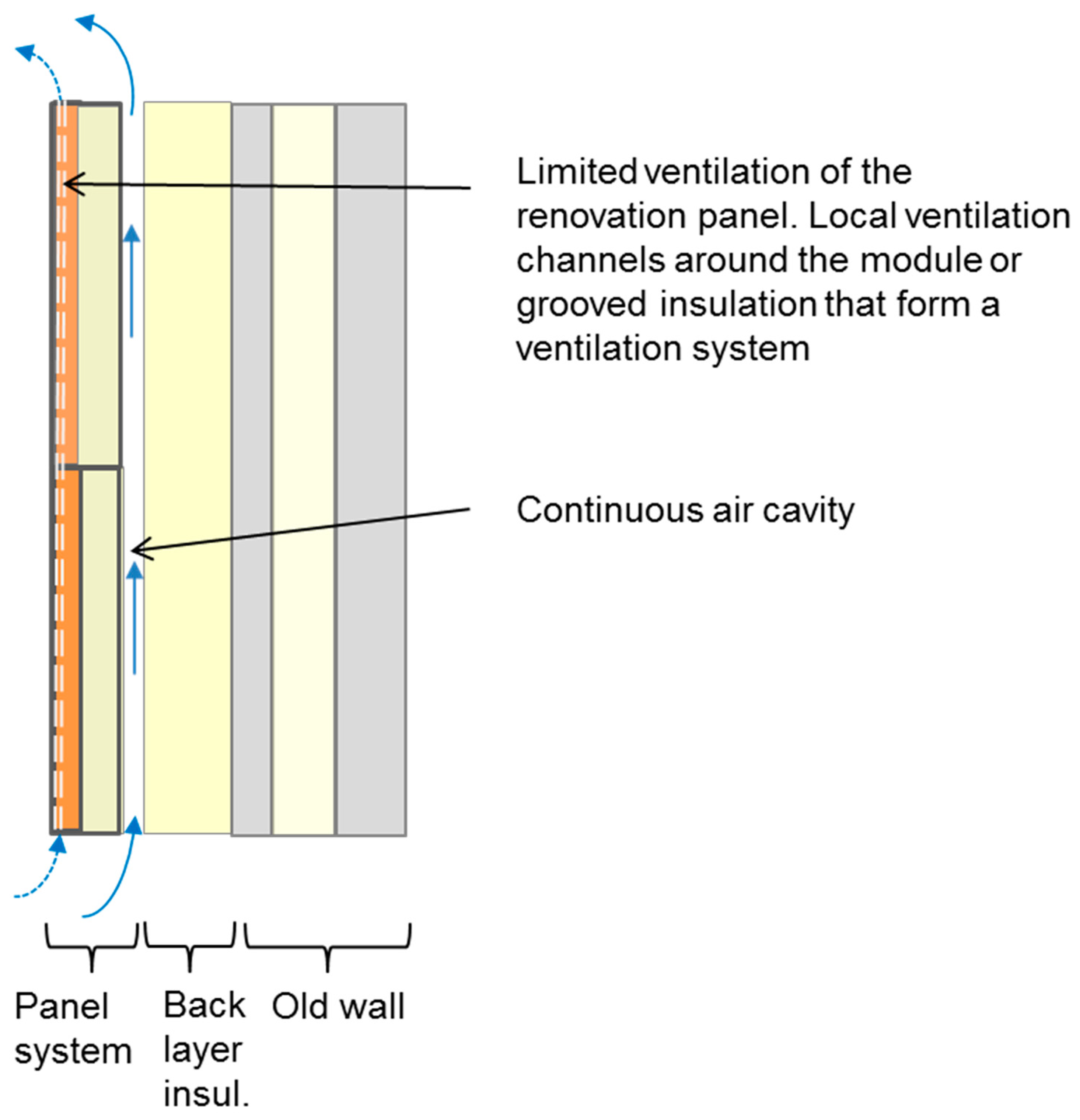
4.3. Limited Ventilation of the Renovation Panel
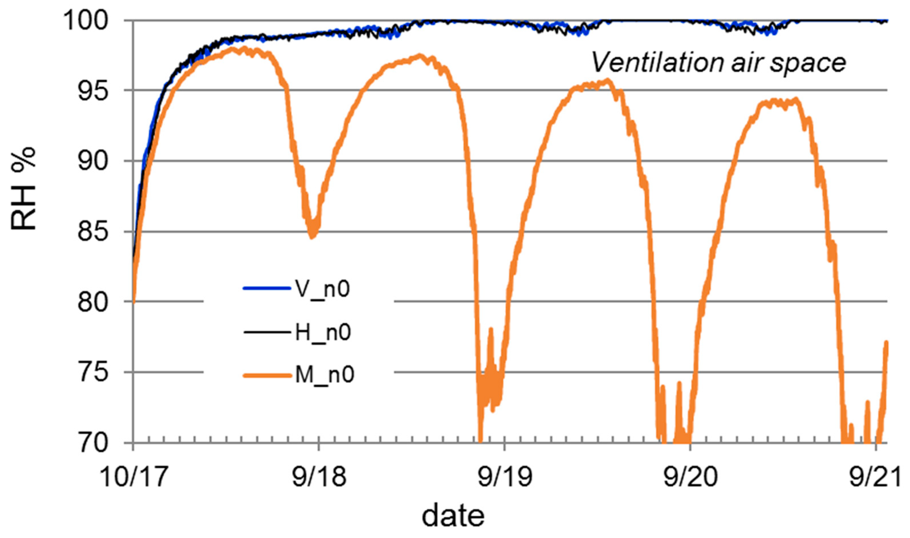
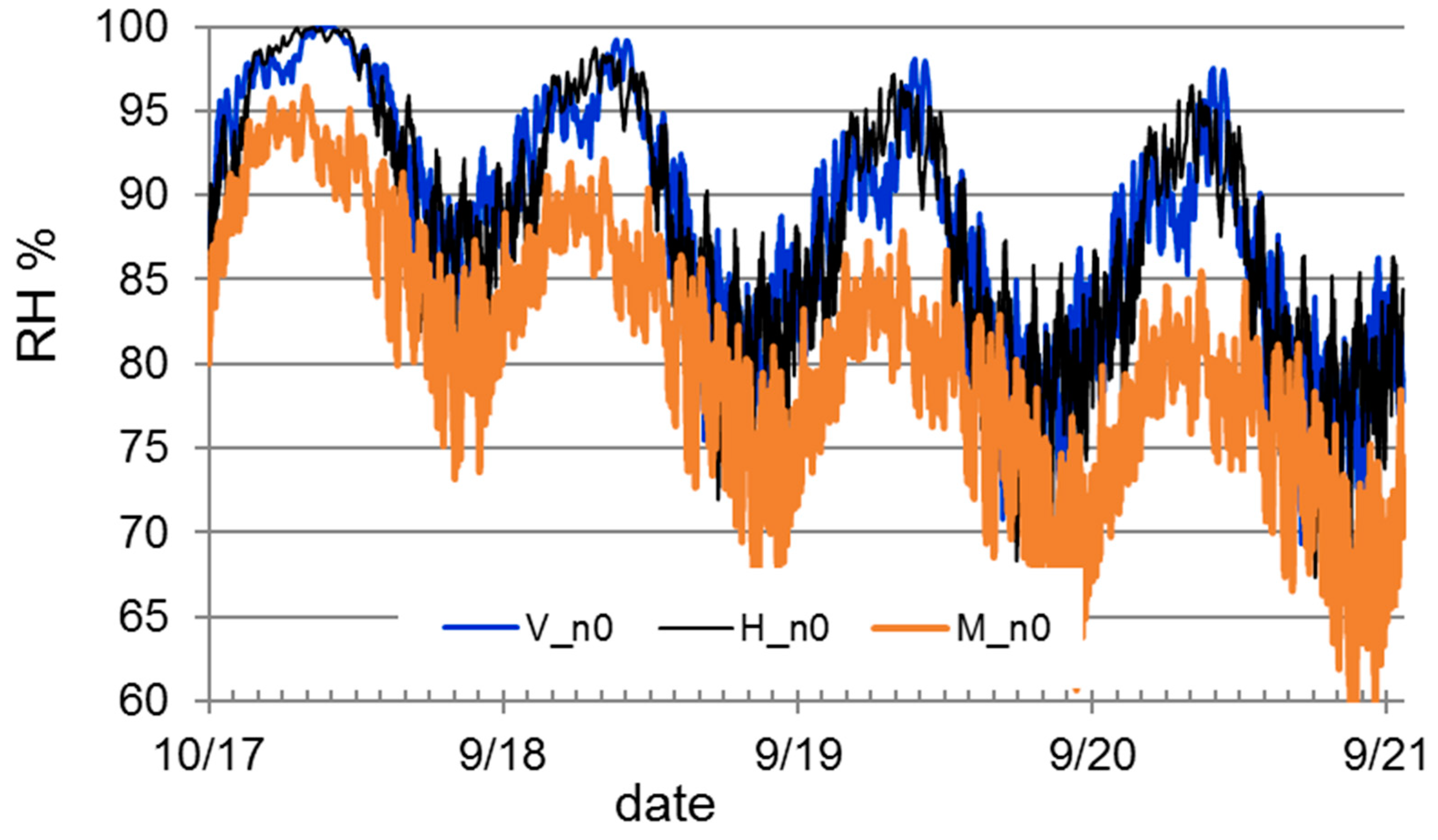
4.3.1. Normal Dry Initial Moisture Content
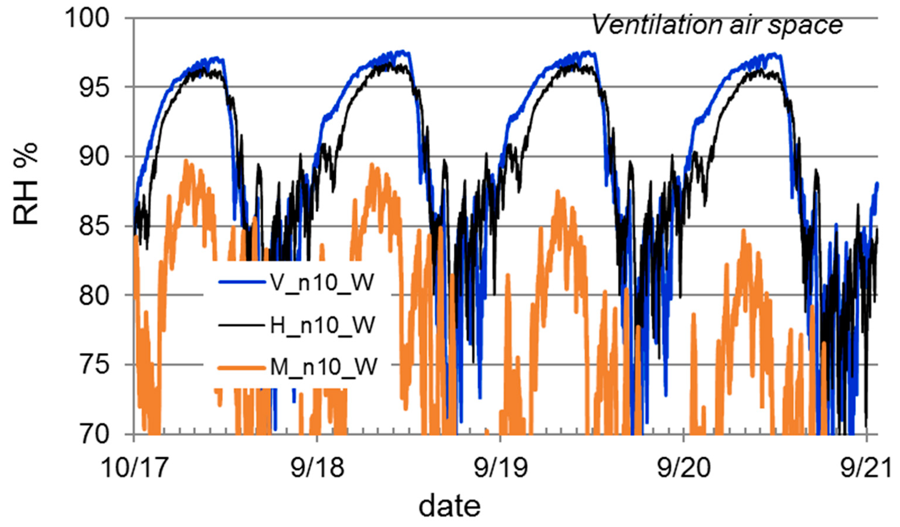
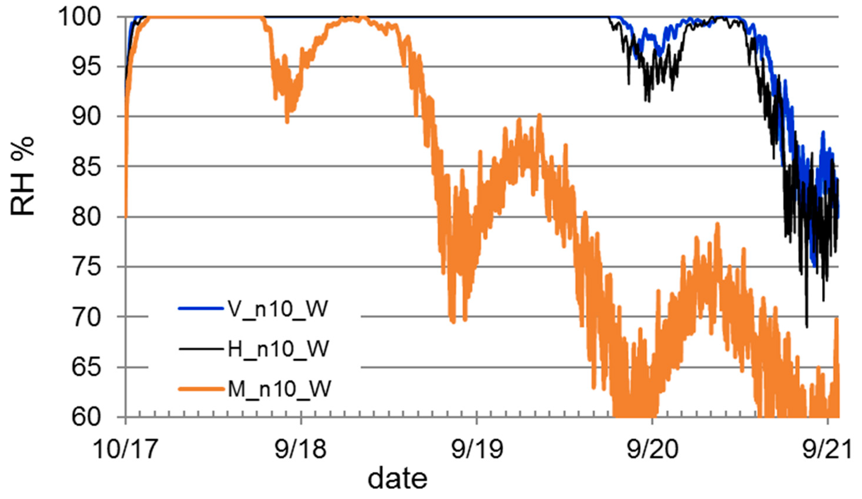
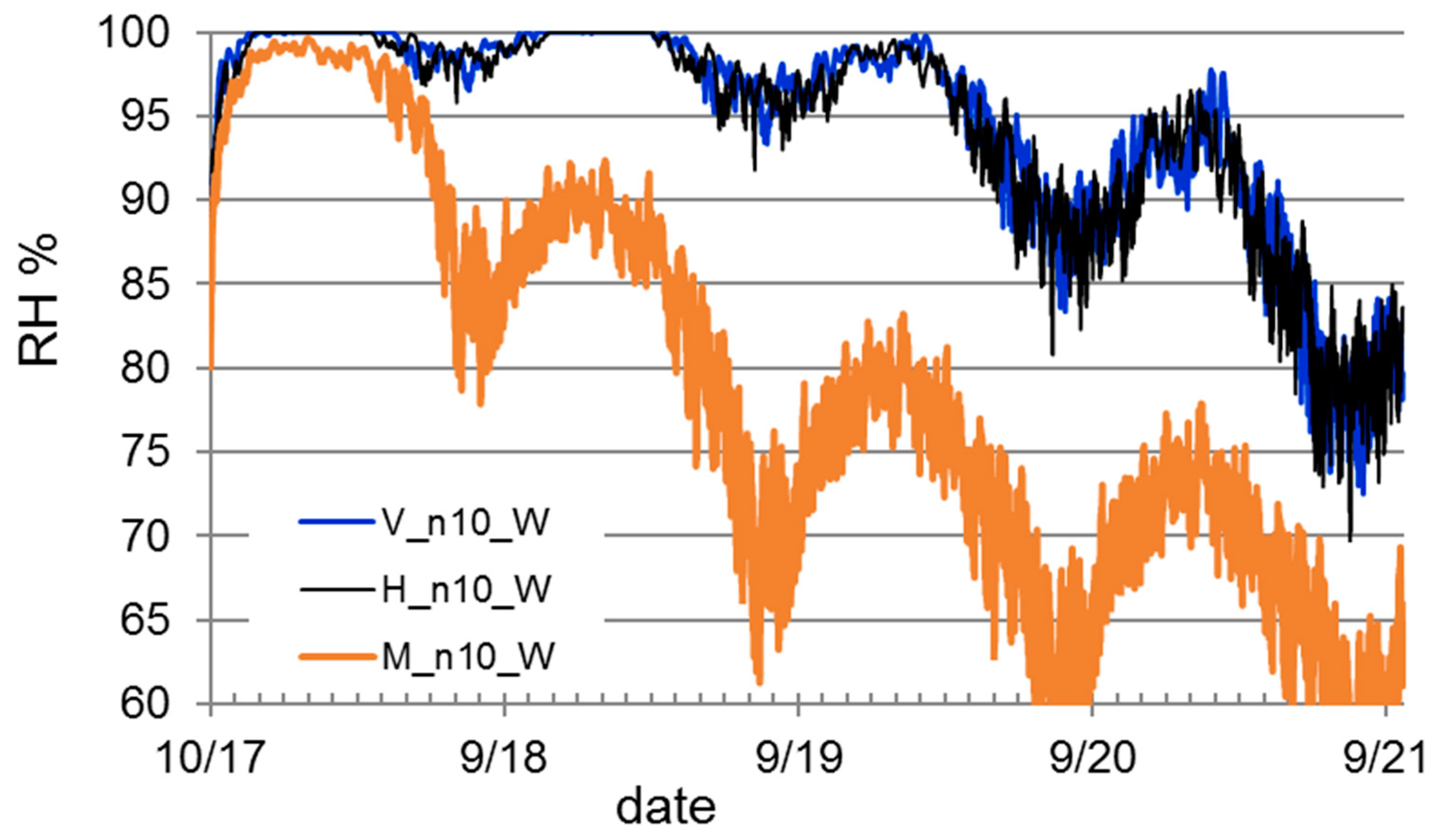
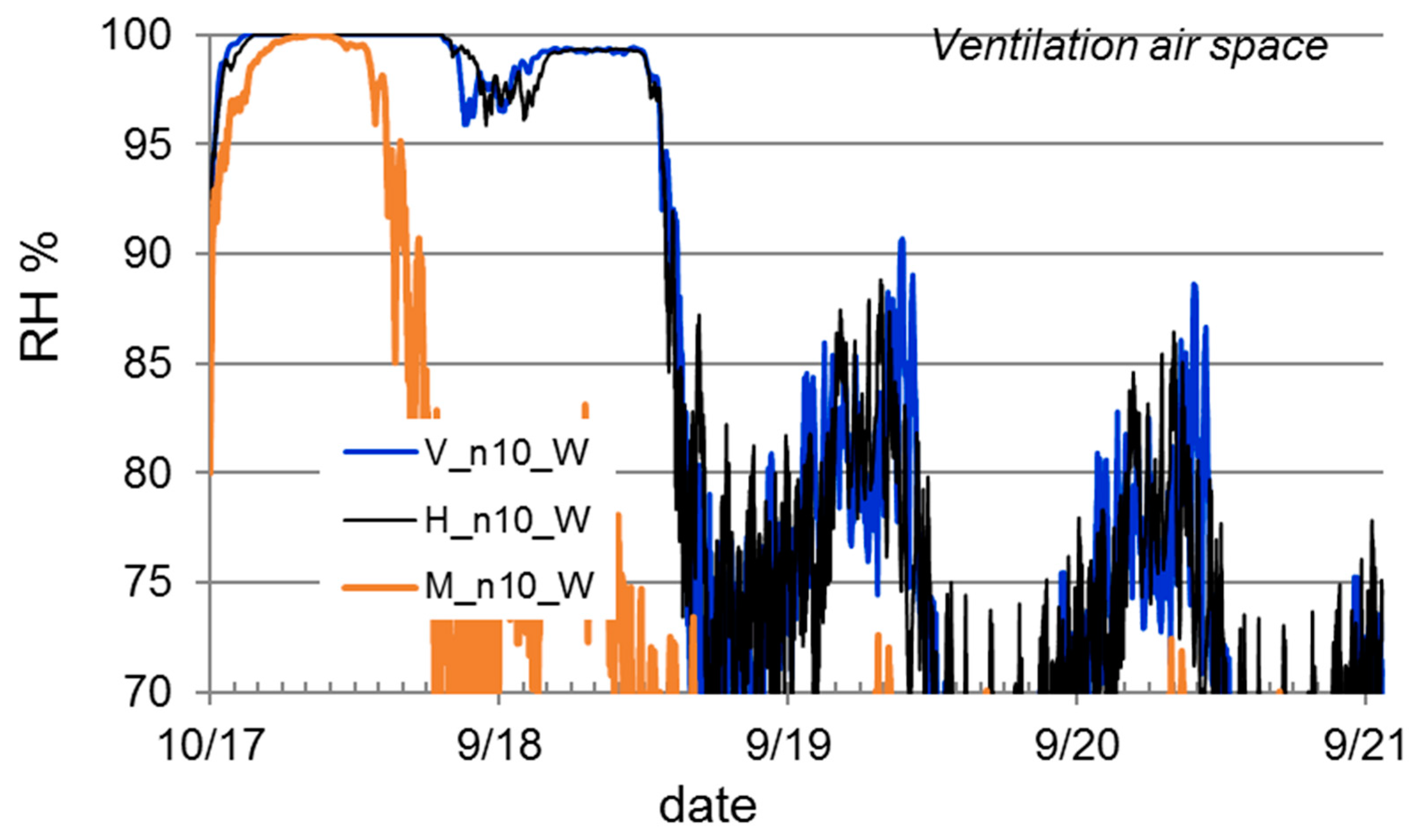
4.3.2. Initially Wet Brick Walls
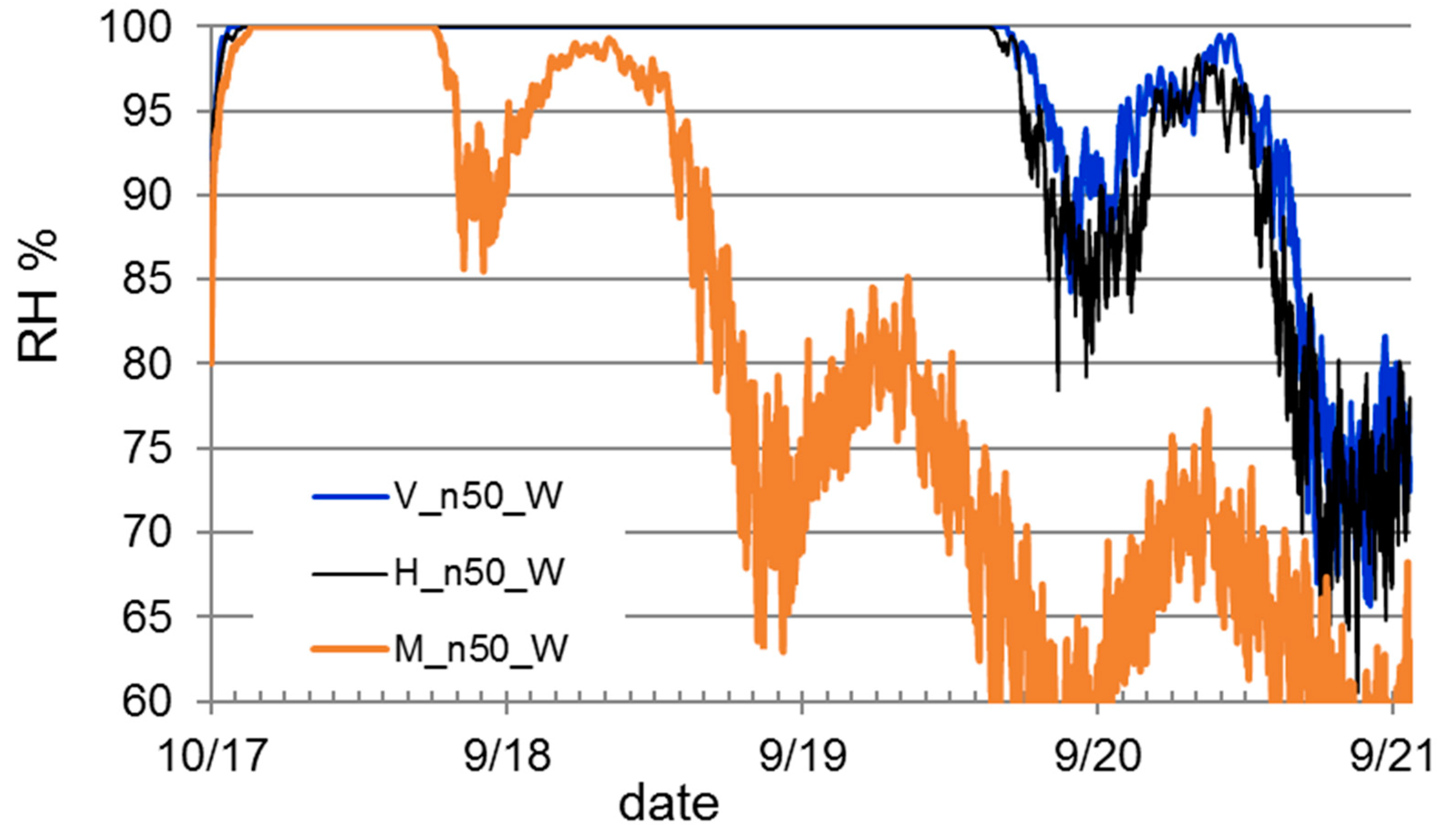
4.3.3. Initially Wet Concrete Sandwich Walls
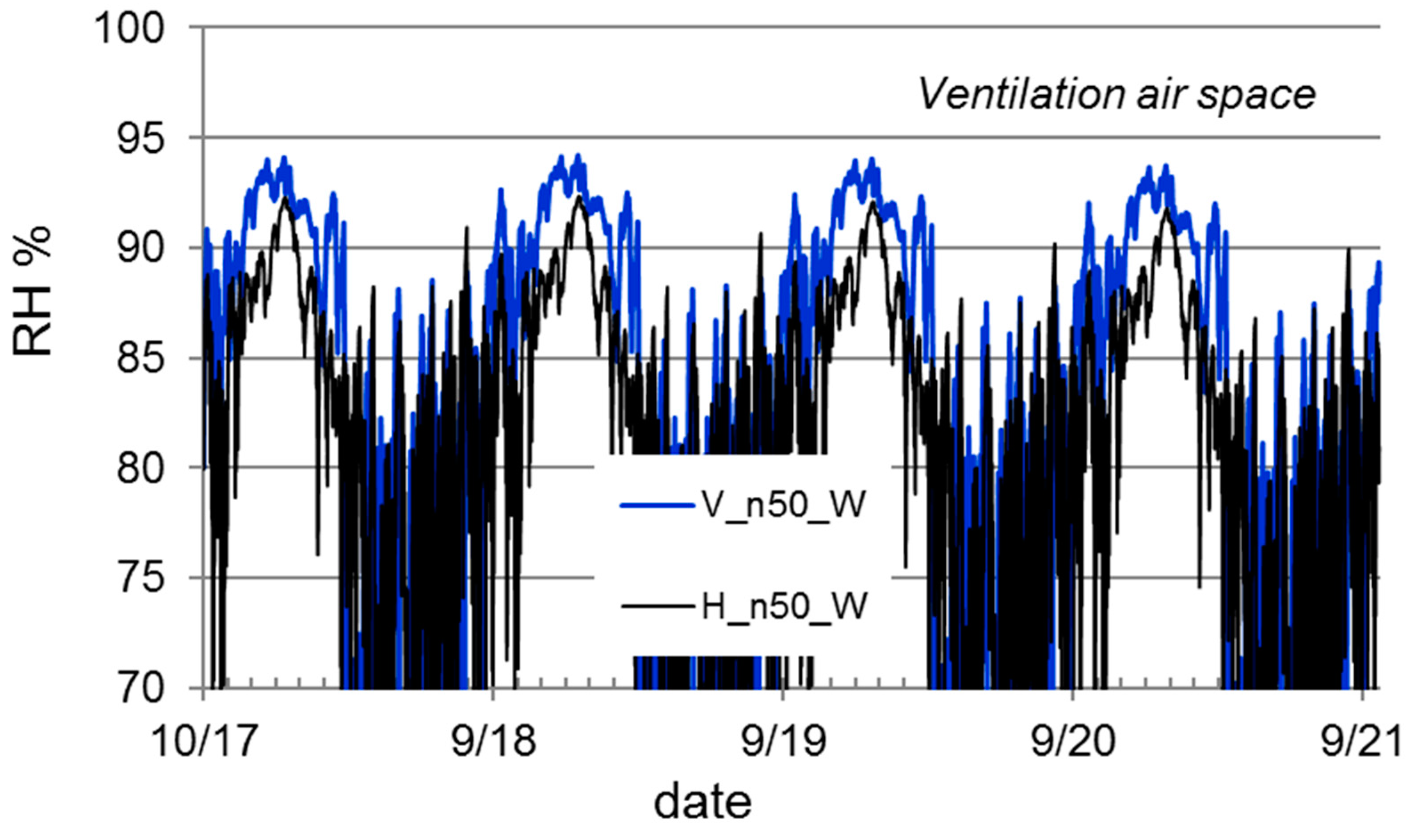
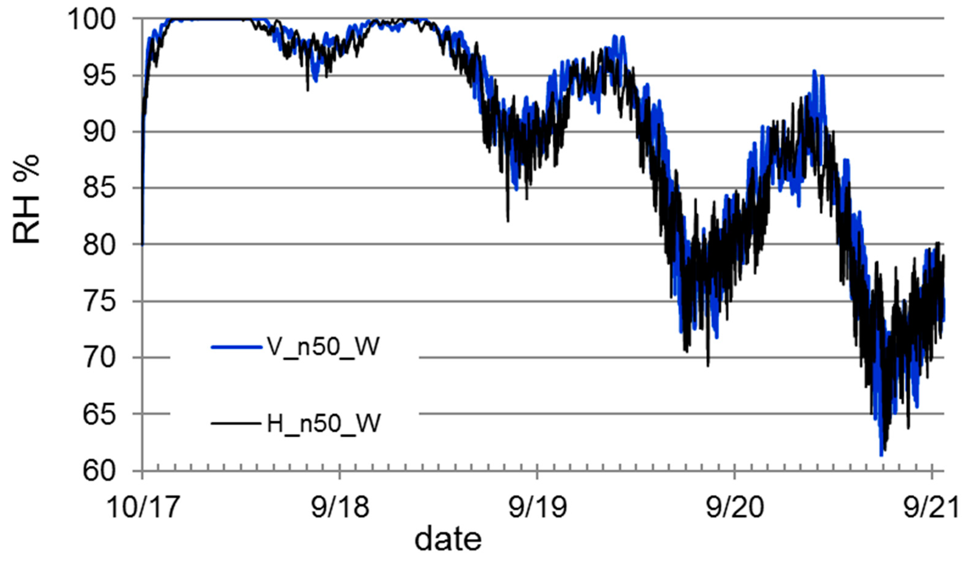
4.4. Wall Ventilation Using Continuous Air Cavity between Material Layers
4.5. Evaluation of the Different Wall Ventilation Schemes
4.6. Effect of Ventilation on the Heat Losses
5. Discussion and Conclusions
- Any exterior renovation system should be able to dry out also outwards under different European climate conditions.
- The drying ability of the system should be ensured in the design phase of the systems.
- When the renovation panel forms a nearly vapor tight outer layer, drying can be achieved only by using ventilation of the structure.
- The possible ventilation rate and drying efficiency depends on the ventilation flow route in the renovated system.
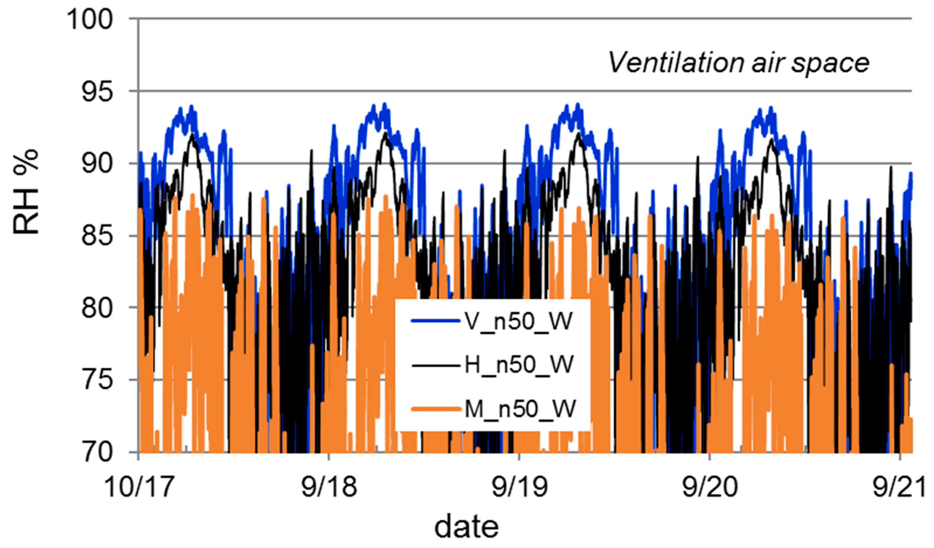
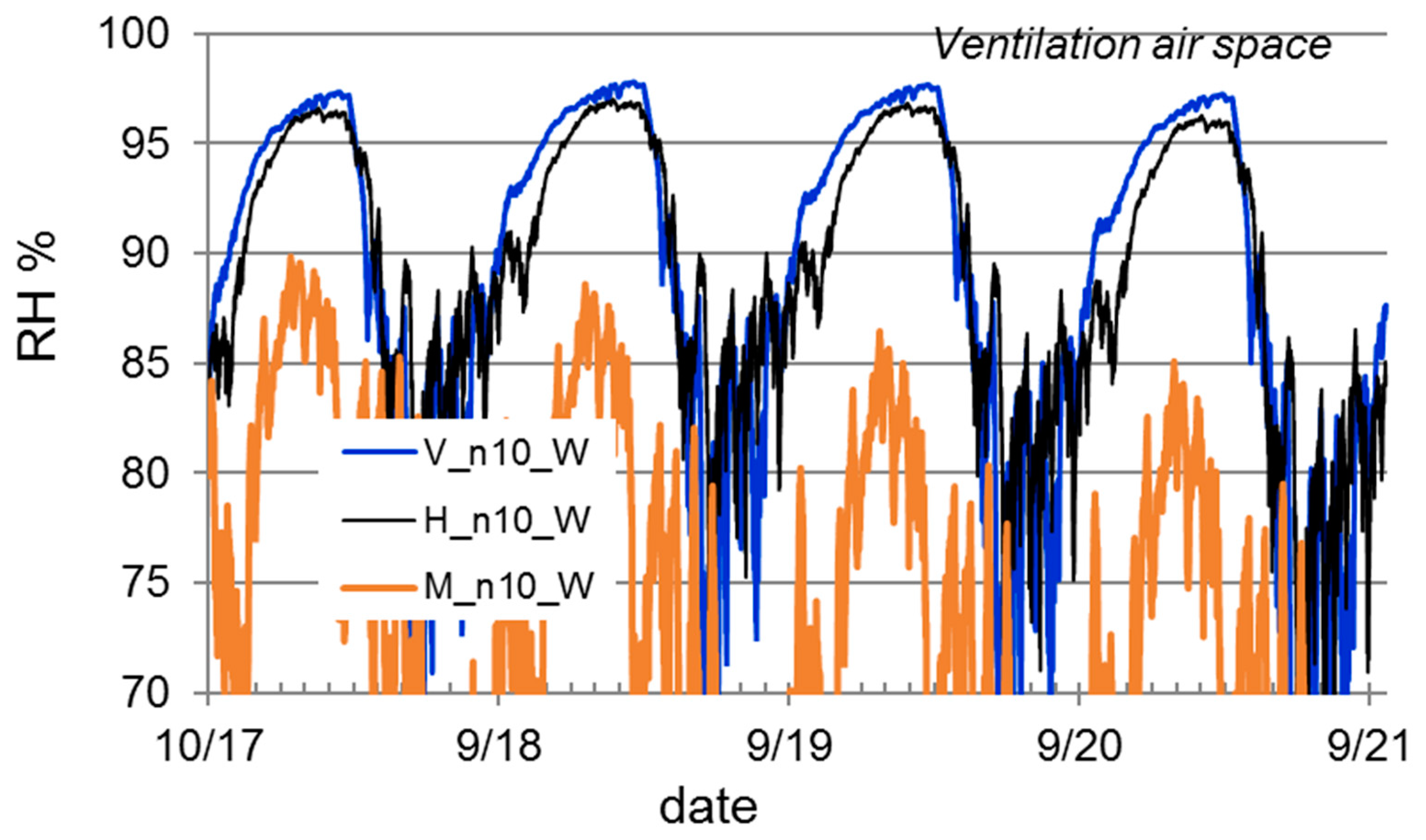
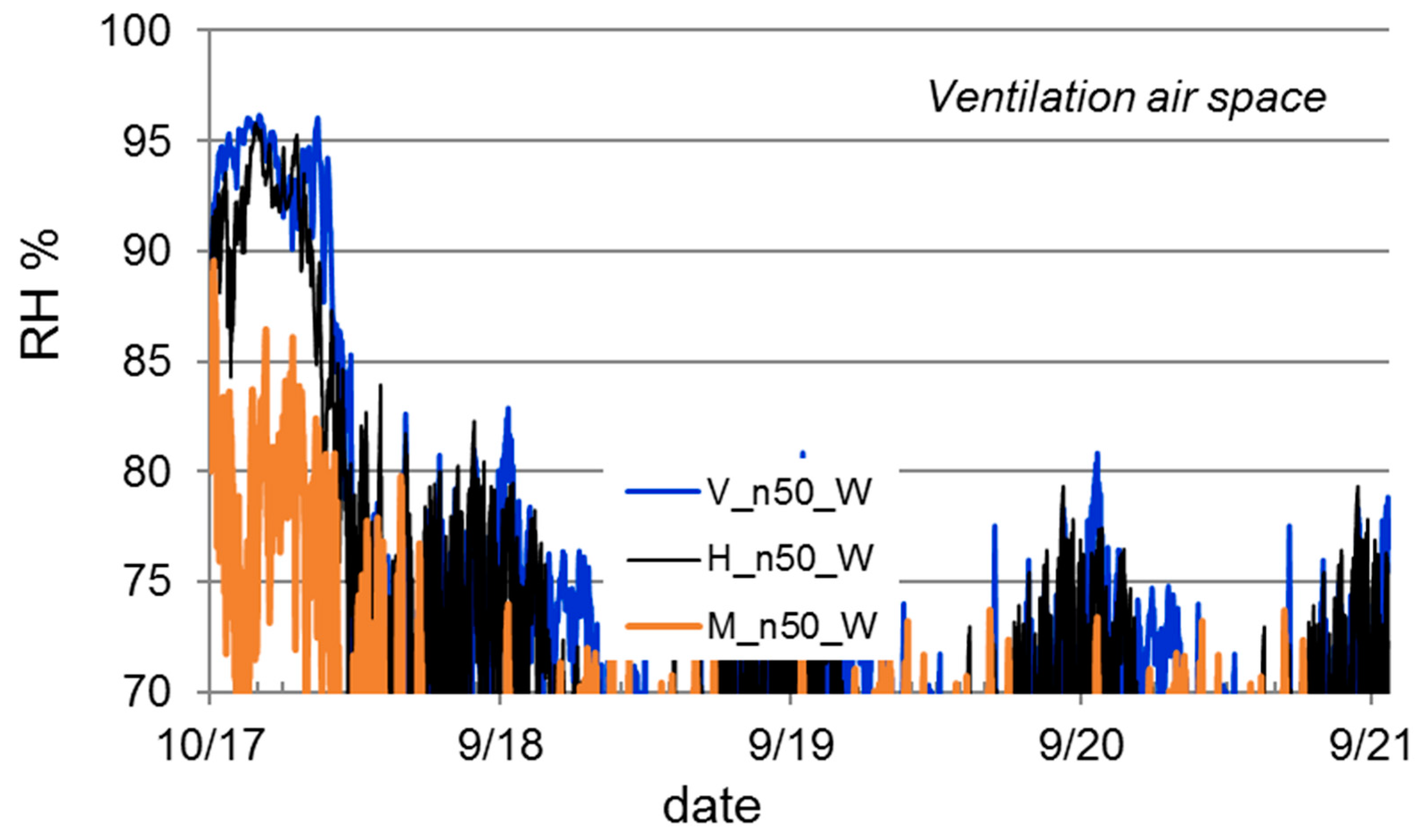
- The drying of initially wet wall structures through the renovated system was possible only when the ventilation air flow rate was high enough (50 air changes in a 10 mm continuous one floor high air cavity) and the ventilation took place between the new insulated module and the back layer insulation. In this case, the effectiveness of the thermal insulation on the exterior side of the ventilation cavity will be reduced severely.
- When the ventilation takes place through local ventilation channels (edge area of the frames) or grooves in thermal insulation close to the exterior surface of the technical module, the drying efficiency remains relatively low. In this case, the existing structure should be dried out before the installation of the Meefs system to a moisture content corresponding to 80% RH equilibrium.
- The requirements for drying efficiency and the ventilation of structures are emphasized in cold and mild climate conditions. In some limited cases, the system can have safe performance under Madrid climate, but the risks are clear in Finnish and German climate conditions.
- Any exterior renovation system of the building façades should be designed from the beginning so that the total performance of the system is taken into account. This means that the drying efficiency, possibly needed ventilation scheme and the true effects on the thermal performance are studied and the system can be applied in practice without risk of malfunctions.
- Ventilation always affects the thermal performance of structures. With air change rate n = 50 1/h between the technical module and installation insulation, the heat losses practically nullify the effect of the thermal insulation on the exterior side of the ventilation cavity. Thus, the real thermal performance does not correspond to the U-values solved under non-ventilated conditions.
Author Contributions
Funding
Acknowledgments
Conflicts of Interest
References
- Economidou, M.; Atanasiu, B.; Despret, C.; Maio, J.; Nolte, I.; Rapf, O. Europe’s Buildings Under the Microscope: A Country-By-Country Review of the Performance of the Buildings; Buildings Performance Institute Europe (BPIE): Brussels, Belgium, 2011. [Google Scholar]
- European Construction Technology Platform (ECTP). EeB PPP. Project Review 2018; European Construction Technology Platform (ECTP): Brussels, Belgium, 2018. [Google Scholar]
- Economist Intelligence Unit. Achieving scale in energy-efficient buildings in China: A view from the construction and real estate sectors. The Economist, 6 August 2013; 1–17. [Google Scholar]
- European Housing Forum. Changing Lifestyles, Changing Climate—The Role of Housing in the EU: Recommendations from the European Housing Forum Towards the EU, Based on a Series of Four Lectures; European Housing Forum: 2010. Available online: https://www.europeanhousingforum.eu/uploads/4/4/0/6/44065093/changing_lifestyles_changing_climate.pdf (accessed on 25 June 2019).
- Tofield, B.; Ingham, M. Refurbishing Europe: An EU Strategy for Energy Efficiency and Climate Action Led by Building Refurbishment; UEA Low Carbon Innovation Centre and Build with CaRe: 2012. Available online: http://archive.northsearegion.eu/files/repository/20140331180352_BuildwithCaReResearchReport-RefurbishingEuropeFeb2012.pdf (accessed on 25 June 2019).
- Artola, I.; Rademaekers, K.; Williams, R.; Yearwood, J. Boosting Building Renovation: What Potential and Value for Europe? European Parliamentary Committees: Brussels, Belgium, 2016; pp. 1–72. Available online: http://www.europarl.europa.eu/RegData/etudes/STUD/2016/587326/IPOL_STU(2016)587326_EN.pdf (accessed on 25 June 2019).
- Paiho, S.; Ahvenniemi, H. Non-Technical Barriers to Energy Efficient Renovation of Residential Buildings and Potential Policy Instruments to overcome Them—Evidence from Young Russian Adults. Buildings 2017, 7, 101. [Google Scholar] [CrossRef]
- Xing, Y.; Hewitt, N.; Griffiths, P. Zero carbon buildings refurbishment—A Hierarchical pathway. Renew. Sustain. Energy Rev. 2011, 15, 3229–3236. [Google Scholar] [CrossRef]
- Sadineni, S.B.; Madala, S.; Boehm, R.F. Passive building energy savings: A review of building envelope components. Renew. Sustain. Energy Rev. 2011, 15, 3617–3631. [Google Scholar] [CrossRef]
- Lewandowski, W.M.; Lewandowska-Iwaniak, W. The external walls of a passive building: A classification and description of their thermal and optical properties. Energy Build. 2014, 69, 93–102. [Google Scholar] [CrossRef]
- Hradil, P.; Toratti, T.; Vesikari, E.; Ferreira, M.; Häkkinen, T. Durability considerations of refurbished external walls. Constr. Build. Mater. 2014, 53, 162–172. [Google Scholar] [CrossRef]
- EAE (European Association for External Thermal Insulation Composite Systems). About ETICS. Available online: https://www.ea-etics.eu/etics/about-etics/ (accessed on 15 February 2019).
- Künzel, H.; Künzel, H.M.; Sedlbauer, K. Long-term performance of external thermal insulation systems (ETICS). Architectura 2006, 5, 11–24. [Google Scholar]
- Amaro, B.; Saraiva, D.; de Brito, J.; Flores-Colen, I. Statistical survey of the pathology, diagnosis and rehabilitation of ETICS in walls. J. Civ. Eng. Manag. 2014, 20, 511–526. [Google Scholar] [CrossRef]
- Heikkinen, P.; Kaufmann, H.; Winter, S.; Larsen, K.E. TES Energy Façade—Prefabricated Timber Based Building System for Improving the Energy Efficiency of the Building Envelope; TES Energy Façade project report. Available online: https://www.holz.ar.tum.de/fileadmin/w00bne/www/04_Forschung/02_Abgeschlossen/TES_EnergyFacade_manual_2009.pdf (accessed on 15 February 2019).
- Cronhjort, Y. Improving the energy efficiency of our built environment through retrofitting and urban infill: TES Energy Facade in the Finnish context. In Proceedings of the SB 2011 Helsinki World Sustainable Building Conference, Helsinki, Finland, 18–21 October 2011. [Google Scholar]
- Cronhjort, Y.; Le Roux, S. Holistic retrofit and follow-up through monitoring: Case Virkakatu, Oulu, Finland. In Proceedings of the NSB 2014 10th Nordic Symposium on Building Physics, Lund, Sweden, 15–19 June 2014; pp. 1171–1179. [Google Scholar]
- Friege, J.; Chappin, E. Modelling decisions on energy-efficient renovations: A review. Renew. Sustain. Energy Rev. 2014, 39, 196–208. [Google Scholar] [CrossRef]
- Meno, S.; Chica, J.A.; Tapia, A.; Del Portillo, L.A. New industrialised developments for the envelope energy retrofitting based on heat recovery ventilation. In Proceedings of the VI International Congress on Architectural Envelopes, Donostia-San Sebastián, Spain, 20–22 June 2012. [Google Scholar]
- Molkoselkä, M. 60–70-Lukujzen Sandwich-Julkisivujen Remontointi ja Lisäeristäminen. Bachelor’s Thesis, Rovaniemen ammattikorkeakoulu, Rovaniemi, Finland, 2011. [Google Scholar]
- Nieminen, J. Innova. Kerrostalosta Passiivitaloksi. Tietopaketti Taloyhtiöille; VTT Technical Research Centre of Finland: Espoo, Finland, 2012. [Google Scholar]
- Paiho, S.; Abdurafikov, R.; Hoang, H. Cost analyses of energy-efficient renovations of a Moscow residential district. Sustain. Cities Soc. 2015, 14, 5–15. [Google Scholar] [CrossRef]
- Mata, É.; Sasic Kalagasidis, A.; Johnsson, F. Cost-effective retrofitting of Swedish residential buildings: Effects of energy price developments and discount rates. Energy Effic. 2015, 8, 223–237. [Google Scholar] [CrossRef]
- Noris, F.; Adamkiewicz, G.; Delp, W.W.; Hotchi, T.; Russell, M.; Singer, B.C.; Spears, M.; Vermeer, K.; Fisk, W.J. Indoor environmental quality benefits of apartment energy retrofits. Build. Environ. 2013, 68, 170–178. [Google Scholar] [CrossRef]
- Brown, N.W.O.; Malmqvist, T.; Bai, W.; Molinari, M. Sustainability assessment of renovation packages for increased energy efficiency for multi-family buildings in Sweden. Build. Environ. 2013, 61, 140–148. [Google Scholar] [CrossRef]
- Tuominen, P.; Forsström, J.; Honkatukia, J. Economic effects of energy efficiency improvements in the Finnish building stock. Energy Policy 2013, 52, 181–189. [Google Scholar] [CrossRef]
- Lindstedt, T.; Kärki, A.; Palmu, T.; Junnonen, J.-M. Teollisten Korjausrakentamismenetelmien Konseptointi; Aalto-Yliopiston Julkaisusarja TIEDE + TEKNOLOGIA 20/2011; Aalto University: Espoo, Finland, 2011. [Google Scholar]
- Lahdensivu, J.; Köliö, A. Suomalaisen betonikerrostalokannan korjaustarpeet. Kiinteistöposti Prof. 2010, 10, 36–38. [Google Scholar]
- Loga, T.; Diefenbach, N.; Stein, B.; Born, R. TABULA Scientific Report Germany: Further Development of the German Residential Building Typology; Institut Wohnen und Umwelt: Darmstadt, Germany, 2012. [Google Scholar]
- Energy Performance Indicator Tracking Schemes for the Continuous Optimisation of Refurbishment Processes in European Housing (EPISCOPE). Scenario Analyses Concerning Energy Efficiency and Climate Protection in Regional and National Residential Building Stocks—Examples from Nine European Countries: EPISCOPE Synthesis Report No. 3; Institut Wohnen und Umwelt: Darmstadt, Germany, 2016. [Google Scholar]
- Capeluto, I.G.; Ochoa, C.E. On the determination of climate strategies for a multifunctional energy retrofit facade system. In Proceedings of the CISBAT 2013: Clean Technology for Smart Cities and Buildings, Lausanne, Switzerland, 4–6 September 2013; pp. 49–54. [Google Scholar]
- Meefs Project. Retrofitting Facade Concept. Available online: https://www.meefs-retrofitting.eu/project/retrofitting-facade-concept.html (accessed on 15 April 2019).
- Paiho, S.; Seppä, I.P.; Jimenez, C. An energetic analysis of a multifunctional façade system for energy efficient retrofitting of residential buildings in cold climates of Finland and Russia. Sustain. Cities Soc. 2015, 15, 75–85. [Google Scholar] [CrossRef]
- Jelle, B.P. Traditional, state-of-the-art and future thermal building insulation materials and solutions—Properties, requirements and possibilities. Energy Build. 2011, 43, 2549–2563. [Google Scholar] [CrossRef]
- Baetens, R.; Jelle, B.P.; Thue, J.V.; Tenpierik, M.J.; Grynning, S.; Uvsløkk, S.; Gustavsen, A. Vacuum insulation panels for building applications: A review and beyond. Energy Build. 2010, 42, 147–172. [Google Scholar] [CrossRef]
- Baetens, R.; Jelle, B.P.; Gustavsen, A. Aerogel insulation for building applications: A state-of-the-art review. Energy Build. 2011, 43, 761–769. [Google Scholar] [CrossRef]
- Riffat, S.B.; Qiu, G. A review of state-of-the-art aerogel applications in buildings. Int. J. Low-Carbon Technol. 2013, 8, 1–6. [Google Scholar] [CrossRef]
- Libessart, L.; Kenai, M.A. Measuring thermal conductivity of green-walls components in controlled conditions. J. Build. Eng. 2018, 19, 258–265. [Google Scholar] [CrossRef]
- Omrany, H.; Ghaffarianhoseini, A.; Ghaffarianhoseini, A.; Raahemifar, K.; Tookey, J. Application of passive wall systems for improving the energy effciency in buildings: A comprehensive review. Renew. Sustain. Energy Rev. 2016, 62, 1252–1269. [Google Scholar] [CrossRef]
- Shameri, M.A.; Alghoul, M.A.; Sopian, K.; Zain, M.F.M.; Elayeb, O. Perspectives of double skin façade systems in buildings and energy saving. Renew. Sustain. Energy Rev. 2011, 15, 1468–1475. [Google Scholar] [CrossRef]
- Agathokleous, R.A.; Kalogirou, S.A. Double skin facades (DSF) and building integrated photovoltaics (BIPV): A review of configurations and heat transfer characteristics. Renew. Energy 2016, 89, 743–756. [Google Scholar] [CrossRef]
- Pietrzyk, K. Risk management of windows performance. Energy Procedia 2015, 78, 2476–2481. [Google Scholar] [CrossRef]
- Werner, A.; Roos, A. Simulations of coatings to avoid external condensation on low U-value windows. Opt. Mater. (Amst). 2008, 30, 968–978. [Google Scholar] [CrossRef]
- Werner, A.; Roos, A. Condensation tests on glass samples for energy efficient windows. Sol. Energy Mater. Sol. Cells 2007, 91, 609–615. [Google Scholar] [CrossRef]
- Souayfane, F.; Fardoun, F.; Biwole, P.H. Phase change materials (PCM) for cooling applications in buildings: A review. Energy Build. 2016, 129, 396–431. [Google Scholar] [CrossRef]
- Kenisarin, M.; Mahkamov, K. Passive thermal control in residential buildings using phase change materials. Renew. Sustain. Energy Rev. 2016, 55, 371–398. [Google Scholar] [CrossRef]
- Hollaway, L.C. A review of the present and future utilisation of FRP composites in the civil infrastructure with reference to their important in-service properties. Constr. Build. Mater. 2010, 24, 2419–2445. [Google Scholar] [CrossRef]
- Kendall, D. Building the future with FRP composites. Reinf. Plast. 2007, 51, 26–33. [Google Scholar] [CrossRef]
- Berardi, U.; Dembsey, N. Thermal and fire characteristics of FRP composites for architectural applications. Polymers (Basel). 2015, 7, 2276–2289. [Google Scholar] [CrossRef]
- Bedon, C. Review on the use of FRP Composites for Facades and Building Skins. Am. J. Eng. Appl. Sci. 2016, 9, 713–723. [Google Scholar] [CrossRef]
- Bjegovic, D.; Pecur, I.B.; Messerschmidt, B.; Milovanovic, B.; Alagusic, M. Influence of fire barriers on fire performance of facades with combustible insulation. In Proceedings of the MATEC Web of Conferences, 2nd International Seminar for Fire Safety of Facades, Lund, Sweden, 11–13 May 2016; p. 11. [Google Scholar]
- Asimakopoulou, E.K.; Kolaitis, D.I.; Founti, M.A. Assessment of Fire Engineering Design Correlations Used to Describe the Geometry and Thermal Characteristics of Externally Venting Flames. Fire Technol. 2017, 53, 709–739. [Google Scholar] [CrossRef]
- Lau, D.; Qiu, Q.; Zhou, A.; Chow, C.L. Long term performance and fire safety aspect of FRP composites used in building structures. Constr. Build. Mater. 2016, 126, 573–585. [Google Scholar] [CrossRef]
- Finnish Communications Regulatory Authority. Automaatiolaitteiden Suojaaminen on Tärkeää. Available online: https://www.viestintavirasto.fi/kyberturvallisuus/tietoturvanyt/2016/11/ttn201611081338.html (accessed on 30 December 2018).
- Official Statistics of Finland. Dwellings and Housing Conditions: 2013, Overview; Statistics Finland: Helsinki, Finland, 2014. [Google Scholar]
- Official Statistics of Finland. Blocks of Flats in Finland, As of 31.12.2012. Number of Buildings by Intended Use and Heating Fuel on 31 Dec. 2012. Available online: http://www.tilastokeskus.fi/til/rakke/tau.html (accessed on 30 October 2013).
- Nemry, F.; Uihlein, A.; Colodel, C.M.; Wittstock, B.; Braune, A.; Wetzel, C.; Hasan, I.; Niemeier, S.; Frech, Y.; Kreißig, J.; et al. Environmental Improvement Potentials of Residential Buildings (IMPRO-Building); JCR Scientific and Technical Reports; Joint Research Centre: Brussels, Belgium, 2008. [Google Scholar]
- Häkkinen, T.; Ruuska, A.; Vares, S.; Pulakka, S.; Kouhia, I.; Holopainen, R. Methods and Concepts for Sustainable Renovation of Buildings; VTT Technical Research Centre of Finland: Espoo, Finland, 2012. [Google Scholar]
- Neuvonen, P. Kerrostalon Julkisivukorjaus. Julkisivun Ominaispiirteet ja Korjaustavan Valinta; Suomen Ympäristö 37/2009; Ympäristöministeriö: Helsinki, Finland, 2009.
- Lahdensivu, J.; Hilliaho, K. Lämmöneristepaksuudet suomalaisissa betonielementtirakenteisissa asuinkerrostaloissa. Kiinteistöposti 2010, 9, 26–28. [Google Scholar]
- Lechtenböhmer, S.; Schüring, A. The potential for large-scale savings from insulating residential buildings in the EU. Energy Effic. 2011, 4, 257–270. [Google Scholar] [CrossRef]
- Medina Benejam, G. Bottom-up characterisation of the Spanish building stock—Archetype buildings and energy demand. Master’s Thesis, Chalmers University of Technology, Gothenburg, Sweden, 2011. [Google Scholar]
- Valencian Institute of Building. Use of Building Typologies for of National Building Stock: Existent Experiences in Spain; Valencian Institute of Building: Valencia, Spain, 2011. [Google Scholar]
- Mata, É.; Medina Benejam, G.; Sasic Kalagasidis, A.; Johnsson, F. Modelling opportunities and costs associated with energy conservation in the Spanish building stock. Energy Build. 2015, 88, 347–360. [Google Scholar] [CrossRef]
- Knaack, U.; Klein, T.; Bilow, M.; Auer, T. Facades: Principles of Construction; Walter de Gruyter GmbH: Berlin, Germany, 2014. [Google Scholar]
- Aksamija, A. Sustainable Facades: Design Methods for High.-Performance Building Envelopes; John Wiley & Sons, Inc.: Hoboken, NJ, USA, 2013; ISBN 978-1-1184-5860-0. [Google Scholar]
- Fraunhofer. What is WUFI®? Available online: https://wufi.de/en/software/what-is-wufi/ (accessed on 31 May 2019).
- Ibrahim, M.; Wurtz, E.; Biwole, P.H.; Achard, P.; Sallee, H. Hygrothermal performance of exterior walls covered with aerogel-based insulating rendering. Energy Build. 2014, 84, 241–251. [Google Scholar] [CrossRef]
- Pasztory, Z.; Peralta, P.N.; Molnar, S.; Peszlen, I. Modeling the hygrothermal performance of selected North American and comparable European wood-frame house walls. Energy Build. 2012, 49, 142–147. [Google Scholar] [CrossRef]
- Coelho, G.B.A.; Henriques, F.M.A. Influence of driving rain on the hygrothermal behavior of solid brick walls. J. Build. Eng. 2016, 7, 121–132. [Google Scholar] [CrossRef]
- Aksamija, A. Design methods for sustainable, high-performance building facades. Adv. Build. Energy Res. 2016, 10, 240–262. [Google Scholar] [CrossRef]


| Property | Issue to be Considered | Relevance to Meefs | Remarks |
|---|---|---|---|
| Thermal properties | |||
| Performance of the thermal insulation under different temperature and moisture conditions | Stability of dimensions and thermal performance properties | Wide variation of potential materials | |
| Thermal insulation that acts as a tolerance compensating layer filling the gap between the rough surface of the old wall and the technical panel | It should be made of soft material with low compression strength to be able to form uniform contact with the old wall surface | Back layer insulation | The thickness of the layer depends on the requirements of the assembly, i.e. rough surface requires thicker back layer insulation |
| Thickness in cold climates | Insulation material | Thick building envelopes possible depending on the insulation material used [34] | New insulation materials with low thermal conductivity allowing a thin insulation layer are expensive [35,36,37] |
| Avoiding varying thermal and moisture loads | Insulation of connections | Electrical and hydraulic connections and installations of the operation control system are integrated into the Meefs structure | Varying loads like liquid water contact and freezing should be considered/prevented |
| Cooling effect of the green façade | Not necessarily profitable in cold climates due to good insulation. Seasonal maintenance. | Green façade units can be integrated into the Meefs [33] | Plants need an irrigation system which means additional costs and produces a new source for moisture loads. The humidity influences thermal conductivities [38]. |
| Overheating of the cavity space | Ventilation in order to diminish overheating in summer and contribute to energy savings in the winter [39] | The Meefs system works as the second skin of the building | Some other issues relevant to double skin façades (e.g., [40]) may also be relevant to the Meefs system |
| Adequate cooling of the photovoltaics (PVs) (efficiency decreases under high temperatures) | Mechanical ventilated façades could ensure adequate cooling of the PVs [41] | PV is one potential technology for the Meefs façade | |
| Restricting effects of thermal bridges | Continuous thermal insulation. Effect of structure frames on the U-value. | Panel framing reduces the thermal resistance of the technical units. Back layer insulation is especially important for the U-value of the renovated system. | Thermal conductivity of the framing material and the form of the frames have strong effect on the thermal bridge effect |
| Moisture properties | |||
| External water condensation | Harmful action of moisture [42] in glazing | U-values of glazing below 1.3 W/m2K, where the risk is most potential [43], can occur also with Meefs technical panels | Different window coating solutions reduce this risk [43,44] |
| Adequate drying efficiency of the renovation system to meet with the loads from indoor air and from the (possibly wet) existing structure | Local accumulation of moisture inside the technical panel or on the boundary between the panel and back layer insulation | No ventilation system planned but requires ventilation at least in Northern and Central-European conditions. | Ventilation affects the thermal performance of the wall. The effect depends on the ventilation route and rates. |
| High enough vapor diffusion coefficient of the back layer insulation | Sufficient moisture flow from the old structure | Risk of high local moisture contents if not considered. Also, consider the drying of the new panel system as a whole. | From back layer insulation, the moisture should be ventilated or transported through the panel insulation to the panel ventilation routes. This aspect is only a part of the moisture performance. A holistic approach is needed to evaluate the whole performance. |
| Condensation of water inside the units including phase-change materials (PCMs) (or inside any other panel that does not allow drying of internal moisture loads) | Protection from rain and frost | Two new technical units are based on PCMs | Proper selection of phase-change materials in different climate conditions has a big impact on their functionality [45,46] |
| Property | Issue to be Considered | Relevance to Meefs | Remarks |
|---|---|---|---|
| Structural properties | |||
| Using fiber reinforced polymer (FRP) | Long-term durability in cold climates | The FRP structure hosts all the installations in the Meefs system. | Benefits of FRPs include long-term durability, weathering resistance, exceptional mechanical properties and suitability for prefabrication [47,48,49] |
| Structural safety | Endurance in weather conditions | Any breakage of the exterior system may cause risks of falling parts to the surroundings. | FRP-based case studies can give more evidence [50] |
| Mechanical strength and structural stability | Clarification of the exact structure | It is not yet clear if the panel framing system is in contact with the existing wall surface | If the frames are supported 140 mm apart from the existing structure the mechanical strength and structural stability aspects have to be taken into account when designing the system. Suitability of the existing structure for the new load bearing requirements. |
| Positioning of the structure | Vertical and horizontal directions and the smoothness of the surface of the old structure is not perfect. How to reach good contact with new system having straight surfaces. | Risk of uncontrolled ventilation routes between the existing wall and the Meefs panel may affect the thermal performance of the system | This aspect is related to the back layer insulation, i.e., smoothing out the irregularities and adjusting the old sloping and the new straight envelope |
| Window openings | Existing windows are left deep from the exterior surface of the new panel/new exterior window structure | The old windows will remain. Their position is not ideal for the thermal or moisture performance due to changes in temperature fields and the possible thermal bridging | Changing windows completely could be considered to overcome this challenge more easily [21] |
| Fire properties | |||
| Tolerance against fire of the thermal insulation | Potentially increased fire load on façades with combustible thermal insulation [51] | Meefs is modular, unlike EPICS, but fire protection needs to be taken into consideration | |
| Fire safety regulations | Requirements differ for ventilated and non-ventilated façades [52] | At least limited ventilation seems to be necessary for the system to have safe moisture performance. Careful selection of thermal insulation materials The fire capacity and other fire properties of the technical units needs to be assessed prior to installation. | Must be defined separately for each building according to regional regulations |
| Tolerance against fire of fiber reinforced polymer (FRP) | Need of experimental fire safety tests [49] Smoke emission under fire needs to be carefully assessed [53] | Used in the structure of Meefs | Pyrolysis simulations are not an effective way to design fire safety of FRPs for architectural applications [49] |
| Cleaning properties | |||
| Cleaning of the supply air in units including PCMs | Air filtering solution in units including PCMs | Valid if replacement air is taken through the unit | Air filters should be easy to change and the air channels easy to clean |
| Cleaning of the ventilation channels | Air flow routes | Some Meefs units are used for fresh air intake or are part of the building ventilation system | The air channels should be easy to clean |
| Data security properties | |||
| Data security | Connection to Internet | Remote control of the operating control system | Unprotected remote management functions in Internet can be used for criminal purposes [54] |
| Year of Construction | Design Value (mm) | Actual Average Values (mm) |
|---|---|---|
| 1963–1975 | 90 | 83 |
| 1976–1985 | 120 | 109 |
| 1986–1996 | 140 | 131 |
| U-values in W/m2K | For a Finnish Apartment Building from the 1970s (Nieminen [21]) | For Finnish Apartment Buildings Built in the 1970s (Häkkinen et al. [58]) | For Buildings in Cold Climate Zones Built before 1975 (Lechtenböhmer and Schüring [61]) | Maximum for Buildings in Cold Climate Zones Built after 1975 (Lechtenböhmer and Schüring [61]) |
|---|---|---|---|---|
| façade | 0.3–0.40 | 0.475 | 0.50 | 0.25 |
| roof | 0.3–0.40 | 0.335 | 0.50 | 0.18 |
| floor | N.A. | 0.48 | 0.50 | 0.19 |
| windows | 2.10–2.40 | 2.44 | 3.00 | 1.60 |
| N.A. = not available | ||||
| Construction Year | Wall | Roof | Floor | Window |
|---|---|---|---|---|
| until 1978 | 1.15 | 0.77 | 1.05 | 2.64 |
| from 1979 to 1994 | 0.64 | 0.40 | 0.71 | 2.37 |
| from 1995 | 0.28 | 0.23 | 0.36 | 1.28 |
| Construction Year | Wall | Roof | Floor | Window |
|---|---|---|---|---|
| before 1975 | 1.7 | 2.25 | 2.25 | 5.8 |
| from 1980 to 2005 | 1.2 | 0.9 | 1.2 | 5.8 |
| from 2006 | 0.86 | 0.49 | 0.64 | 3.5 |
| Case Code | Climate | Initial Conditions Wet/Dry | Air Change Rate in 10 mm Continuous Air Cavity n, 1/h | Old Wall: Concrete (C) or Brick (B) |
|---|---|---|---|---|
| V_n0 | Vantaa, Finland | Dry | 0 | C and B |
| H_n0 | Holzkirchen, Germany | Dry | 0 | C and B |
| M_n0 | Madrid, Spain | Dry | 0 | C and B |
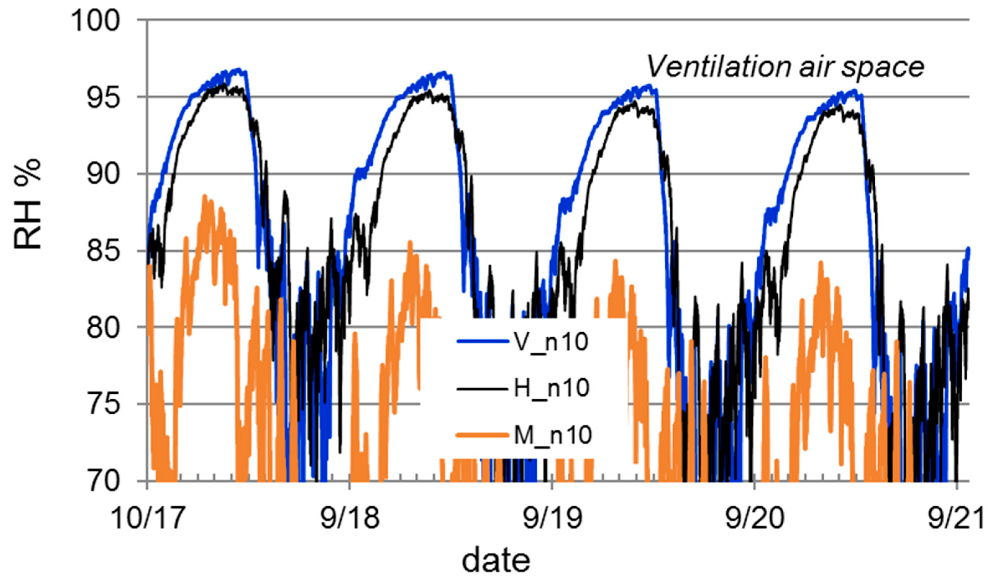
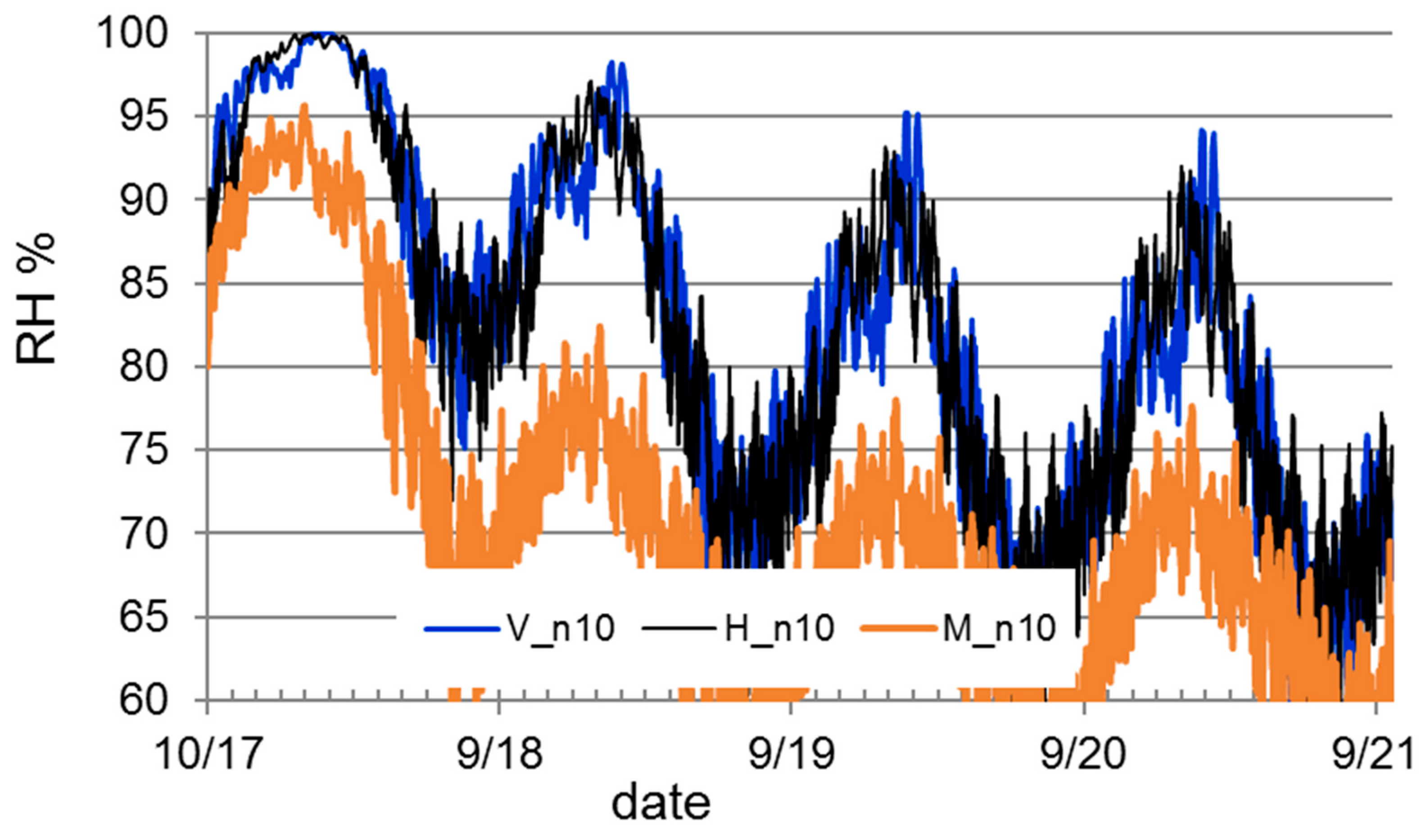
| V_n10 | Vantaa, Finland | Dry | 10 | B |
| H_n10 | Holzkirchen, Germany | Dry | 10 | B |
| M_n10 | Madrid, Spain | Dry | 10 | B |
| V_n10_W | Vantaa, Finland | Wet | 10 | C and B |
| H_n10_W | Holzkirchen, Germany | Wet | 10 | C and B |
| M_n10_W | Madrid, Spain | Wet | 10 | C and B |
| H_n50_W | Holzkirchen, Germany | Wet | 50 | C and B |
| M_n50_W | Madrid, Spain | Wet | 50 | B |
| V_n50_W | Vantaa, Finland | Wet | 50 | C and B |
| Case Code | Climate | Initial Conditions Wet/Dry | Air Change Rate in 10 mm Continuous Air Cavity n, 1/h | Old Wall: Concrete (C) or Brick (B) |
|---|---|---|---|---|
| V_n10_W | Vantaa, Finland | Wet | 10 | B |
| H_n10_W | Holzkirchen, Germany | Wet | 10 | B |
| M_n10_W | Madrid, Spain | Wet | 10 | B |
| H_n50_W | Holzkirchen, Germany | Wet | 50 | B |
| M_n50_W | Madrid, Spain | Wet | 50 | B |
| V_n50_W | Vantaa, Finland | Wet | 50 | B |
© 2019 by the authors. Licensee MDPI, Basel, Switzerland. This article is an open access article distributed under the terms and conditions of the Creative Commons Attribution (CC BY) license (http://creativecommons.org/licenses/by/4.0/).
Share and Cite
Paiho, S.; Ojanen, T.; Pinto Seppä, I.; Paavola, M. Critical Performance Aspects of Retrofitting Apartment Buildings Using a Multifunctional Façade System. Buildings 2019, 9, 184. https://doi.org/10.3390/buildings9080184
Paiho S, Ojanen T, Pinto Seppä I, Paavola M. Critical Performance Aspects of Retrofitting Apartment Buildings Using a Multifunctional Façade System. Buildings. 2019; 9(8):184. https://doi.org/10.3390/buildings9080184
Chicago/Turabian StylePaiho, Satu, Tuomo Ojanen, Isabel Pinto Seppä, and Martta Paavola. 2019. "Critical Performance Aspects of Retrofitting Apartment Buildings Using a Multifunctional Façade System" Buildings 9, no. 8: 184. https://doi.org/10.3390/buildings9080184
APA StylePaiho, S., Ojanen, T., Pinto Seppä, I., & Paavola, M. (2019). Critical Performance Aspects of Retrofitting Apartment Buildings Using a Multifunctional Façade System. Buildings, 9(8), 184. https://doi.org/10.3390/buildings9080184