Article

Assessing Structural Damage after a Severe Wildfire: A Case Study

by
Angeliki Papalou
* and
Dimitrios K. Baros
Department of Civil Engineering, University of Peloponnese; 26334 Patras, Greece
*
Author to whom correspondence should be addressed.
Buildings 2019, 9(7), 171; https://doi.org/10.3390/buildings9070171
Submission received: 27 June 2019 / Revised: 13 July 2019 / Accepted: 16 July 2019 / Published: 18 July 2019

Abstract

:
Wildfires have always been a threat to forests and areas of high combustible vegetation. When they are not kept under control, they can spread to residential areas, creating severe damage and destruction. This paper examines the effects of the extreme heat conditions that developed during a wildfire on buildings as a function of their construction type. One of the deadliest wildfires in Greece (July 2018) is considered as a case study, and the damage that occurred to buildings during this event is presented. The temperature of the various structural subsystems in extreme heat conditions was estimated using the finite element method. Parameters that influenced the corresponding temperature distribution were identified. Simple guidelines are given to prevent or reduce damage in buildings exposed to wildfires.

1. Introduction

Every year during dry seasons, wildfires start in areas of combustible vegetation all over the world. Under extreme weather, these fires can spread uncontrollably, destroying everything in their path, including vegetation and structures, and endangering human lives.
Preventing the ignition and spreading of wildfires is not an easy task. It involves actions that have to take place prior or after the start of a fire:
  • Opening security roads in the forest area, creating fire breaks, and limiting available fuel with prescribed burns and vegetation thinning;
  • Monitoring and detecting the ignition of a fire in its early stages based on human surveillance and/or advanced detection and monitoring techniques, including satellite remote sensing, forest animals as biological sensors, image processing, etc. [1];
  • Educating people in the community to avoid the initiation of fires when high winds are expected, especially in areas with combustible vegetation;
  • Acquiring (by the government, local or national) all necessary equipment and personnel for fire suppression and having a plan of action to reduce fire spread and to direct people who are being evacuated from areas of danger.
There are factors that influence the spread of a wildfire that cannot be avoided, such as weather conditions (wind speed, direction, relative humidity, air temperature) and topography [2]. Wildfires can spread uncontrollably, destroying the infrastructure of an exposed area. There are several factors that influence the vulnerability of a building to wildfires, including its location, the flammability of the materials outside and inside the structure, and the design and construction materials used [3].
The design of fire-resistant structures is an important issue, especially in areas surrounded by combustible vegetation. The safety of lives and the protection of structures in case of fire are the subjects of fire codes. Active and passive control systems can be used to increase the fire safety of a structure [4]. Active control systems such as automatic sprinklers may fail to work under extreme conditions, and passive fire protection may be the last resort to contain fires and protect the structure. Passive fire protection adopts structural design strategies (i.e., the usage of fire-resistant materials) that prevent the spreading of a fire and protect buildings from collapsing.
Under regular conditions, structural analysis provides the tools to safely design a structure to support its loads. Most current design codes are based on the method of limit state design (strength and serviceability limit states). The main concern for a structure exposed to fire is its ability to maintain its strength and stability.
Research about structural damage associated with wildfires is limited [5]. Previous work has mainly focused on investigating the behavior of buildings exposed to fire, using models of buildings and creating fire conditions. Bailey et al. [6] examined the behavior of a full-scale steel frame building. Lamont et al. [7] examined the structural stability of a steel frame building without passive fire protection. The finite element method and a standard fire model were used for determining the displacements and strains developed in structural members exposed to fire. Foster et al. [8] presented thermal and structural results using numerical models based on a full-scale building during a compartment fire test. Wald et al. [9] investigated the temperature development and distribution of internal forces within various structural elements of a compartment on a steel–concrete composite frame building during a large-scale fire test.
It is essential for engineers to understand the effects a fire may have on structures depending on the material they consist of and to predict the loads and the properties a structure may have under these extreme conditions. This paper outlines the design process used to predict the loads and the remaining capacity a structure will have when exposed to fire. The behavior of different construction materials exposed to fire is analyzed using as a case study one of the deadliest wildfires that have occurred in Greece, on July 23, 2018. A numerical analysis was performed to identify the temperature of structural subsystems exposed to fire conditions using the finite element method. Simple guidelines are given to prevent or reduce damage in buildings exposed to extreme heat conditions.

2. Fires and Structures

A wildfire may start from lightning, from damaged power cables, from people’s activities, etc., and can spread uncontrollably, destroying large areas of land. The stages of a typical fire include the “ignition stage”, when the combustion material (fuel), oxygen, and heat interact, creating a fire; the ”growth stage” (flash-over), when the fire (depending on the amount of fuel and oxygen) starts growing; the “fully developed stage”, when all fuel is used and the fire reaches its maximum extent; and the “decay stage”, when most of the fuel or the oxygen has been used and the fire gradually ceases.
The behavior of structures exposed to fire depends on several factors, including construction materials, the temperatures developed, and the duration of the fire. The temperatures developed inside structural members must be estimated either for design purposes or for a damage assessment of a structure exposed to fire. These temperatures can be estimated if the gas temperature throughout the burning time is known. The gas temperature developed from a wildfire is more difficult to predict and depends on weather conditions [10].
Gas temperatures can be estimated using a design fire. A nominal fire or a natural fire can be selected. A nominal fire is represented by a standard curve of uniform gas temperature with time (e.g., ISO 834-1 [11]). It is independent of fuel and ventilation conditions and continues with time without decaying. A natural fire depends on fuel, geometry, and ventilation conditions, and it decays following the stages of a typical fire, as described above. Simplified models can be used to predict gas temperature, such as one-zone models, two-zone models, and computational fluid dynamics. Nominal fires are often used for designing purposes.
After calculating the maximum gas temperature, the temperature at the surface of the material can be estimated and is usually 50–100 °C less than the gas temperature depending on the time the member is exposed to fire. Inside the structural member, the temperature reduces by depth. High temperatures change the properties of the materials, leading to a reduction in the strength and modulus of elasticity. If the members’ expansion is restricted, additional stresses develop inside the member, which plays an important role especially in steel members.
In structural design, fire is considered an accidental event. Structures exposed to fire loads are examined only in the ultimate limit state, and it is sufficient to only analyze parts of the structure without the need to examine the whole. A load combination that can be used is
G k + ψ 1 Q k , 1 + ψ 2 Q k , 2
where the safety factor for the permanent load Gk is unity; Qk,1, Qk,2 are the leading and accompanying variable actions, respectively; and ψ1, ψ2 are the corresponding building factors.
In the first step of fire design, the temperatures of the materials are estimated. Then, a structural analysis is performed considering a load combination such as the one discussed above, including also the forces induced by the fire. These forces are developed due to the constraints that may exist in the structure that restrict its thermal expansion or that are due to large deformations [4]. In the structural analysis, material properties either are modified from the beginning (adopting the reduced due to fire values), or a step-by-step analysis is considered with increasing loads and decreasing property values [12].
According to Eurocodes [13,14,15], the fire design strength ( f d , f i ) of construction materials, including steel, concrete, and masonry, is given by
f d , f i = k f i f k γ Μ , f i ,
where f k is the characteristic strength of the material at normal temperature, k f i is a reduction factor depending on the material’s temperature, and γ M , f i is a partial safety factor for the strength of the material for the fire conditions, usually taken as 1.
The fire design strength ( f d , f i ) of timber [16] is given by
f d , f i = k mod , f i k f i f k γ Μ , f i ,
where k f i and k mod , f i are modification factors for fire considering the strength and effects the temperature has on the strength of timber, respectively.

3. Construction Materials Exposed to Fire

In the following sections, a brief discussion of the properties, the expected behavior, and ways to improve the fire resistance of each construction material composing the structural form is presented. The effects of a fire on the behavior of materials can also be identified as effects from direct and indirect fire actions. Damages from indirect fire actions occur when thermal expansion and deformation are constrained.

3.1. Behavior of Concrete in Fires

Concrete is composed of aggregates, cement, and water, and when it is reinforced, of steel bars. It has low thermal conductivity, and it is considered to be noncombustible. Its good behavior in fires is further improved when it consists of carbonate or lightweight aggregates. As long as the temperature of concrete is below 500 °C, concrete’s strength is not affected. Above 500 °C, the compressive strength of concrete starts to reduce (direct fire action). The strength reduction is higher for high-strength concrete. The modulus of elasticity is also reduced with an increase in temperature, and this reduction starts at temperatures lower than 200 °C. After concrete cools down, it regains most of its strength. Concrete’s steel bars are protected when the concrete cover is still in place. If they are exposed directly to fire, their yield strength is reduced considerably above 400 °C. When steel bars cool down, they regain most of their strength [17].
The concrete’s color after exposure to fire can give a good estimation of the temperature the concrete’s surface reached. Below 300 °C, there is not a real change in color. Above 300 °C and below 600 °C, the color is pink; between 600 and 900 °C, the color changes to gray; and above 900 °C it is buff-yellow. Smut also appears even below 300 °C.
The increase in temperature may cause large axial forces if thermal expansion is restrained (indirect fire action). The usual damage that can occur is spalling of the cover concrete that protects the steel bars from corrosion and fire. This is most likely due to an increase in the pore pressure in the cement paste. Other possible damage may include sagging of beams and slabs, diagonal cracking in continuous beams, cracking of columns, etc.
For concrete, the addition of polypropylene fibers to the concrete mix can increase its resistance to spalling. The fibers melt under high temperatures, creating passages for the vapors to escape [18]. The increase of cover thickness increases the protection of the steel bars, and the use of fire resistance coatings can increase the safety of the buildings exposed to fire.

3.2. Behavior of Masonry in Fires

Masonry structures are incombustible and behave better than concrete, steel, or timber structures exposed to fire. The surfaces of the units experience high temperatures (leading to flaking and discoloration of the outer layer), while the material underneath the surface is protected, experiencing lower temperatures. Low-porosity materials experience more disruption than porous ones do. Calcareous units maintain their compressive strength up to 700 °C, while the modulus of elasticity is reduced [12]. Brick units above 400 °C experience a reduction in strength and the modulus of elasticity. Discoloration (direct fire action) is due to both shoot deposition and thermal oxidation of iron-containing minerals [19]. Thermal oxidation can begin to take place at temperatures as low as 250–300 °C. Different minerals produce differently colored changes. This may not comprise the structural stability of the material, but it can generate aesthetic damage.

3.3. Behavior of Timber in Fires

Timber structures are vulnerable to fire, since wood is a combustible material. Heavy and light timber structures behave differently when exposed to fire. Heavy timber structures [20] consist of large-dimension members that behave well in fires. When they are ignited, their surfaces burn, creating a layer of char that protects the inner wood for a long time.
The moisture of the inner wood below the layer of char evaporates above 100 °C. At 200 °C, the wood thermally decomposes. The charring temperature is about 300 °C [3]. The strength and modulus of elasticity of wood are reduced with increasing temperatures (direct fire action).
Resistance against fire for light timber structures consisting of smaller-dimension members can be provided by protective materials such as gypsum boards, fiber cement panels, and protective coatings. The connections can be protected either by being inside the wood section or by enclosure by a gypsum board. Gusset plates have poor behavior in fires when they are unprotected.

3.4. Behavior of Steel in Fires
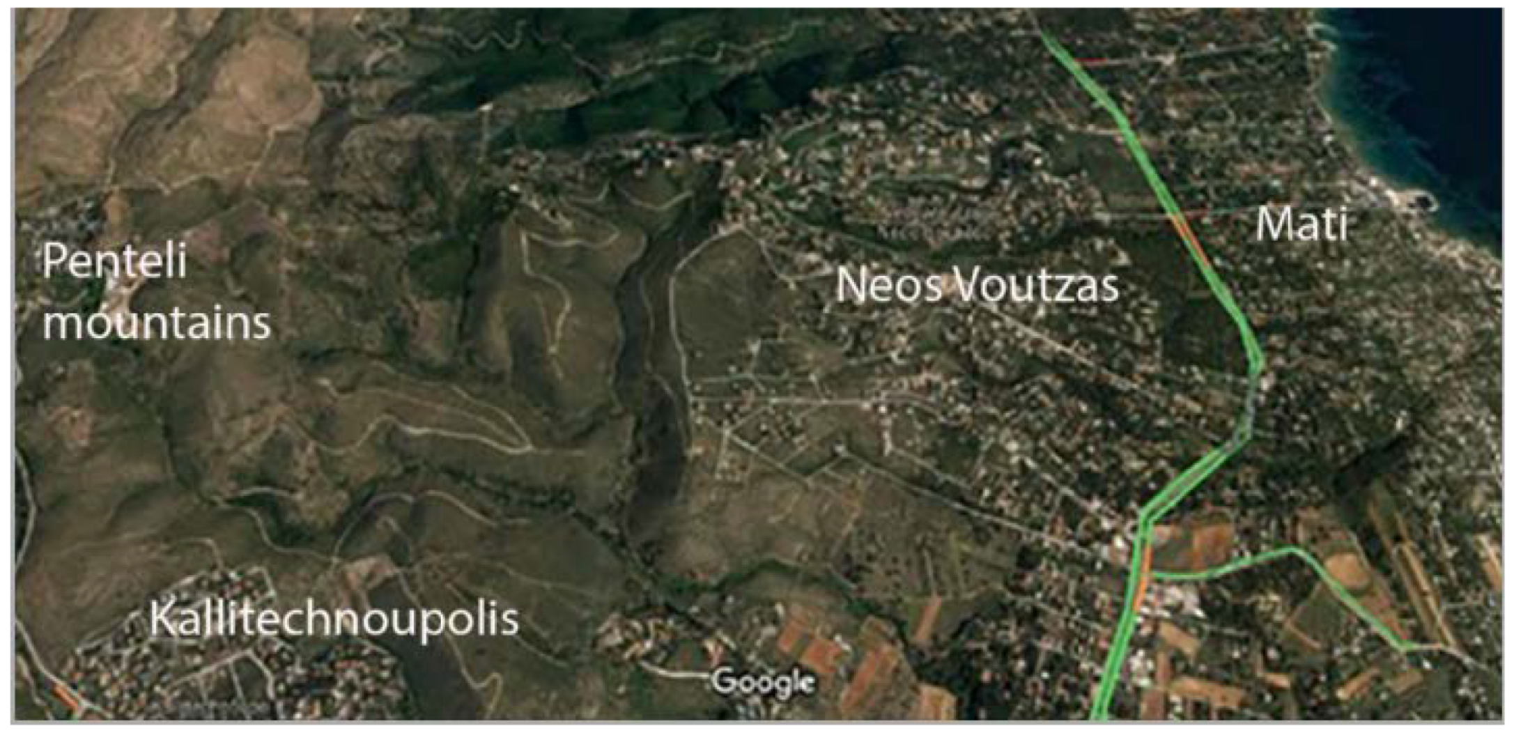
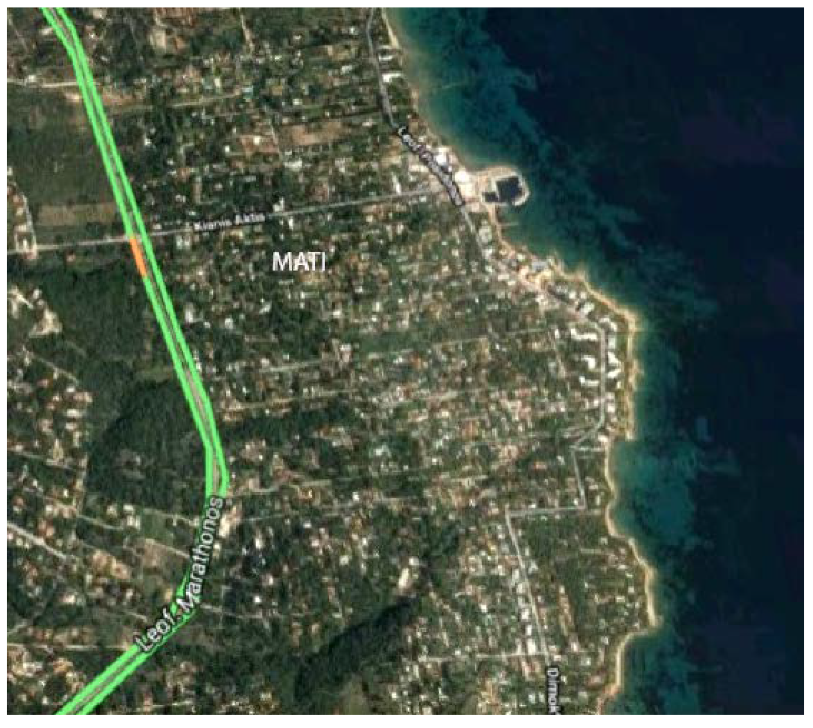
Steel members are usually thin and have higher thermal conductivity than other construction materials. When they are unprotected, they perform poorly when exposed to fire [4]. Steel’s yield strength and modulus of elasticity drop considerably above 300 °C. At about 700 °C, strength and stiffness reduce to half values (direct fire action). In addition, restricted thermal expansion can result in large deformations and the buckling of thin steel members (indirect fire actions). If the temperature does not exceed 700 °C and there is no prolonged exposure, the mechanical properties return to their initial values after cooling down. If steel members are exposed to temperatures above 700 °C for more than 20 min, oxidation will appear on the surface, as well as pitting and a loss of cross-sectional thickness (direct fire action). Above 870 °C, their properties do not return to their initial values. Steel members will have smaller ductility and higher strength and hardness.
The protection of steel members from fire can be achieved through several methods, including the application of certain coatings (for example, intumescent coating), encasement with concrete, and enclosure with boards (calcium silicate, gypsum, timber, etc.)

4. Case Study

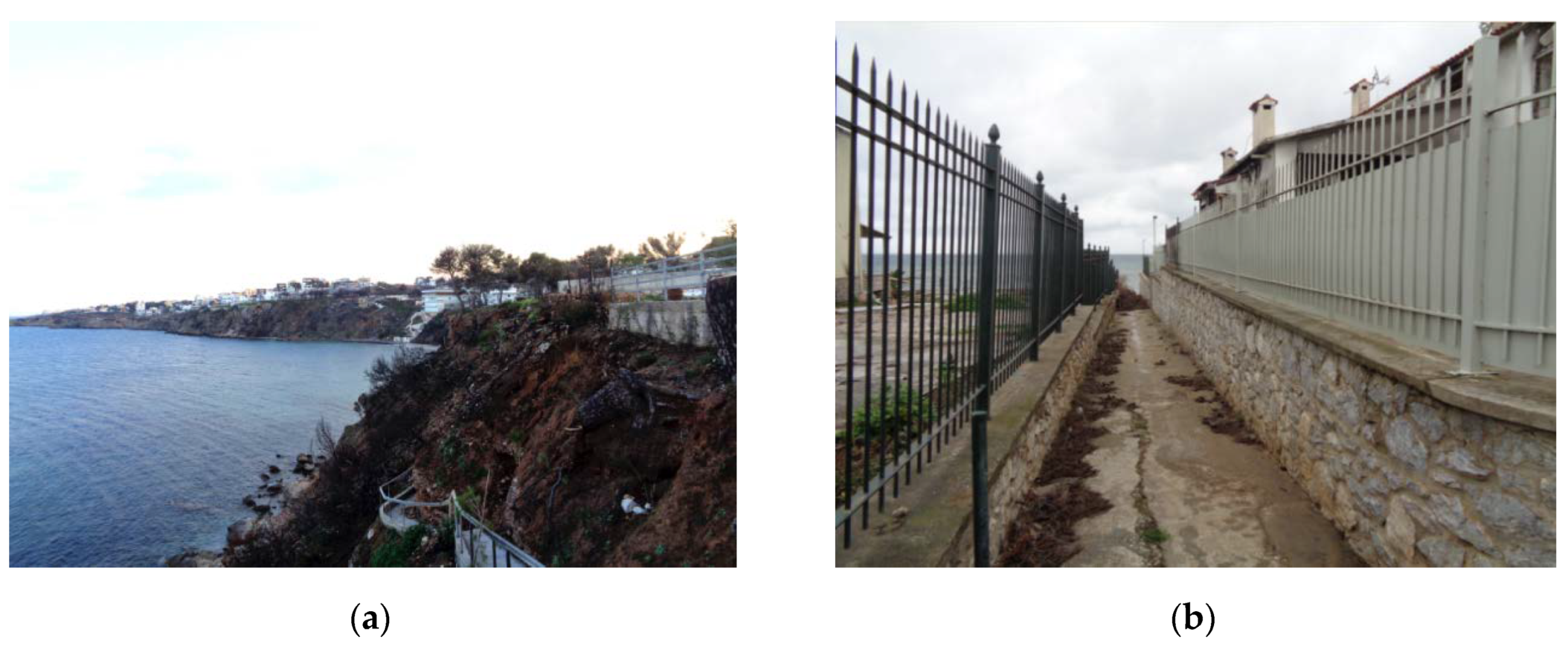
4.1. Details of the Occurrence of the Wildfire

Mati is a Greek village located on the east coast of Attica that attracts many visitors and tourists during the summer. Its proximity to Athens (30 km) makes it an ideal second-home place for Athenians. On July 23, 2018, a wildfire started in the Penteli Mountains west of Mati, passing through Kallitechnoupolis and Neos Voutzas (Figure 1), destroying everything in its path, and reaching the village in the evening.
A significant fraction of Mati (Figure 2) is covered by pine trees, which are highly flammable. Strong winds (stronger than 90 km/h, reaching 120 km/h at times) moved the fire uncontrollably over the area. A 20-m-wide highway (Marathon Ave., green color) that separated the main inhabited part of the village from a higher-altitude area was considered to be a barrier for fires and a safety measure for the village, but it did not restrain the fire. With both of its sides covered by pine trees, it was easily crossed by the fire.
The high winds moved the fire toward the coast. Someone would think that the beach would provide an easy escape for Mati’s inhabitants and visitors. Unfortunately, the beach is not easily accessed, since most of the area is elevated several meters above sea level (Figure 3a) and the existence of fences along the coast blocks access to the sea. The few narrow paths (Figure 3b) leading toward the sea were difficult to locate in the smoky air conditions the fire had created.
During these difficult hours, with insufficient/wrong guidance from the local authorities and a limited number of fire-fighting vehicles, panic was created. Some people left the area using their cars, but others got stuck in the narrow roads, losing their lives. Most of the people that reached the sea were able to survive after staying there for several hours before they were rescued. There were, however, several people who could not find the path toward the sea in the smoky, suffocating conditions and suffered a tragic death. Twenty-six of them were found together at the top of a cliff above the sea. The total death toll in Mati and the villages next to it reached 102. Figure 4 shows part of the destruction the day after the fire.

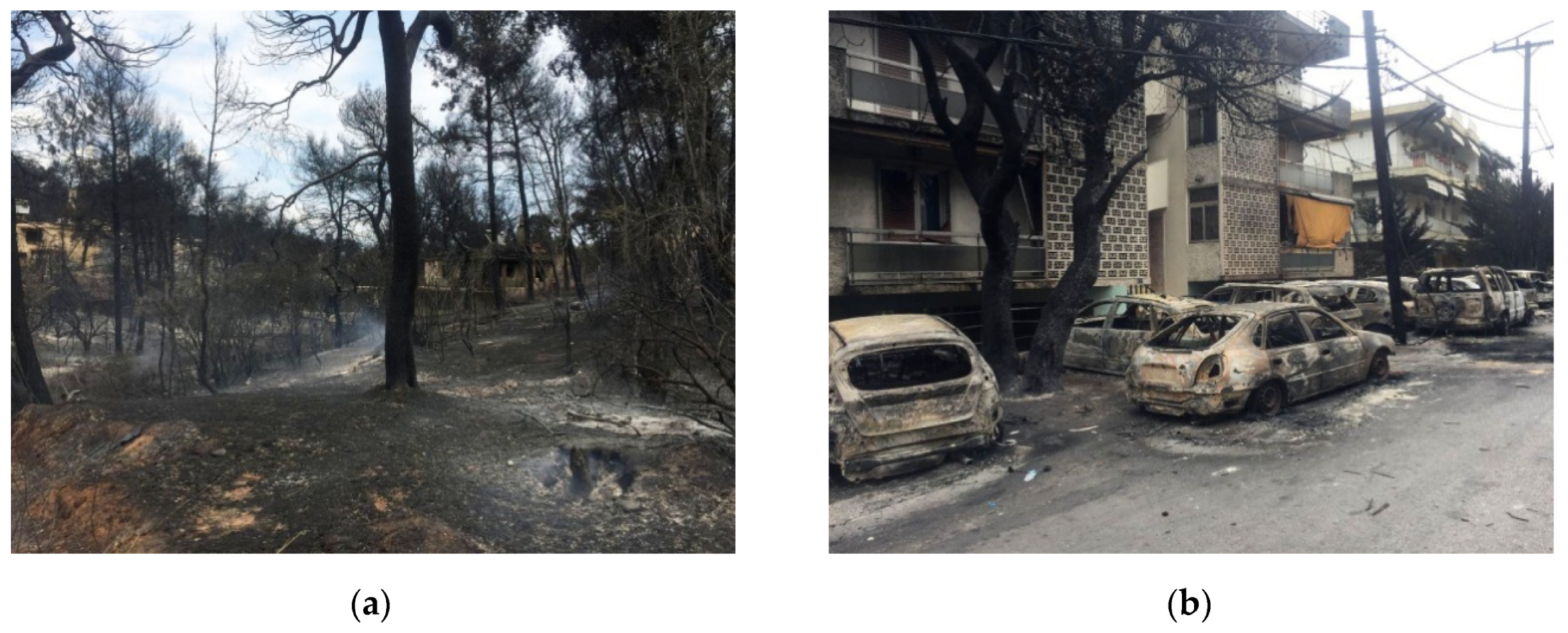
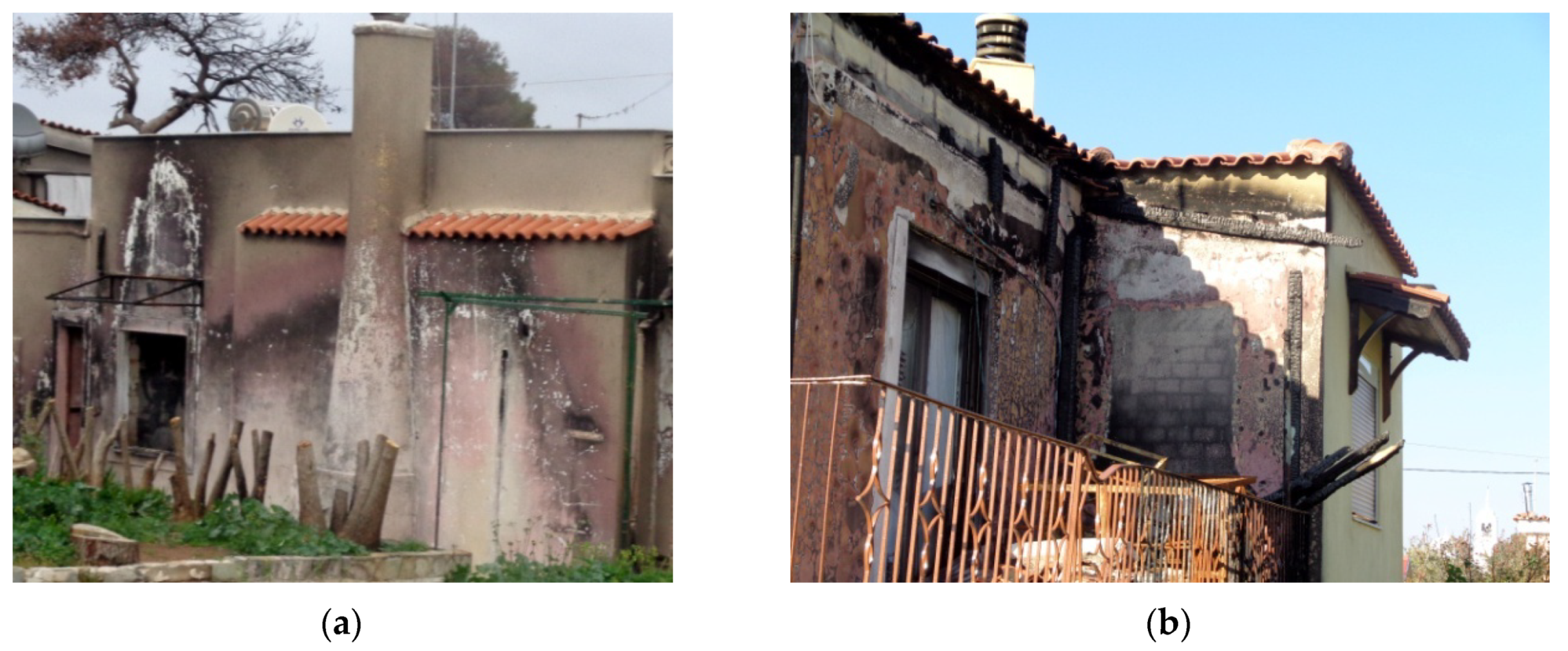
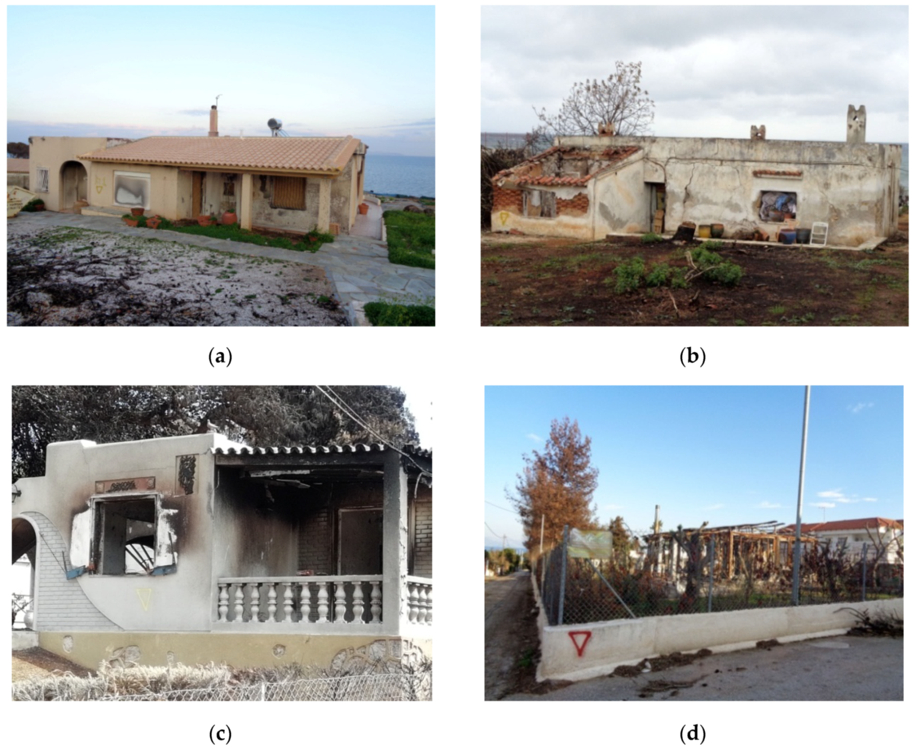
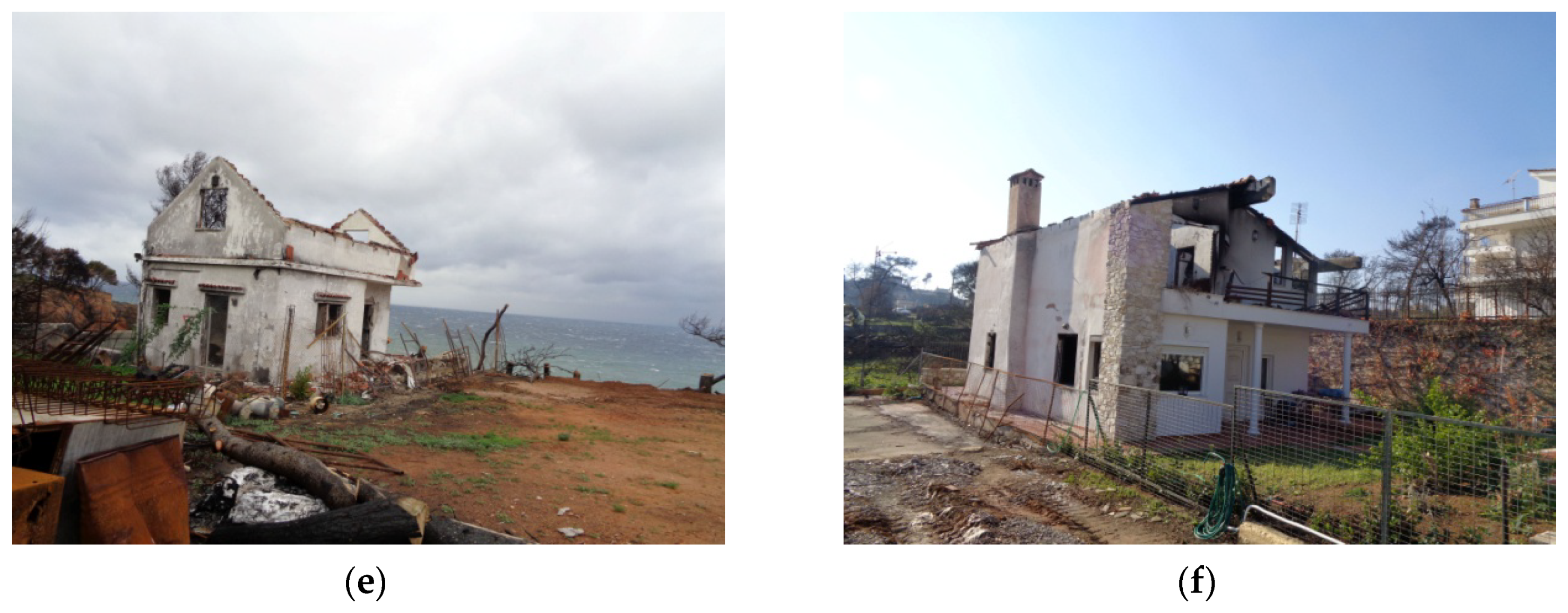
4.2. Observed Damage

The buildings in Mati were mainly made from concrete frames with brick infill walls or masonry with timber/concrete roofs. A few buildings had steel or wood frames as a light structural system and plaster boards as infills. In the following sections, the damage observed in the buildings is described.

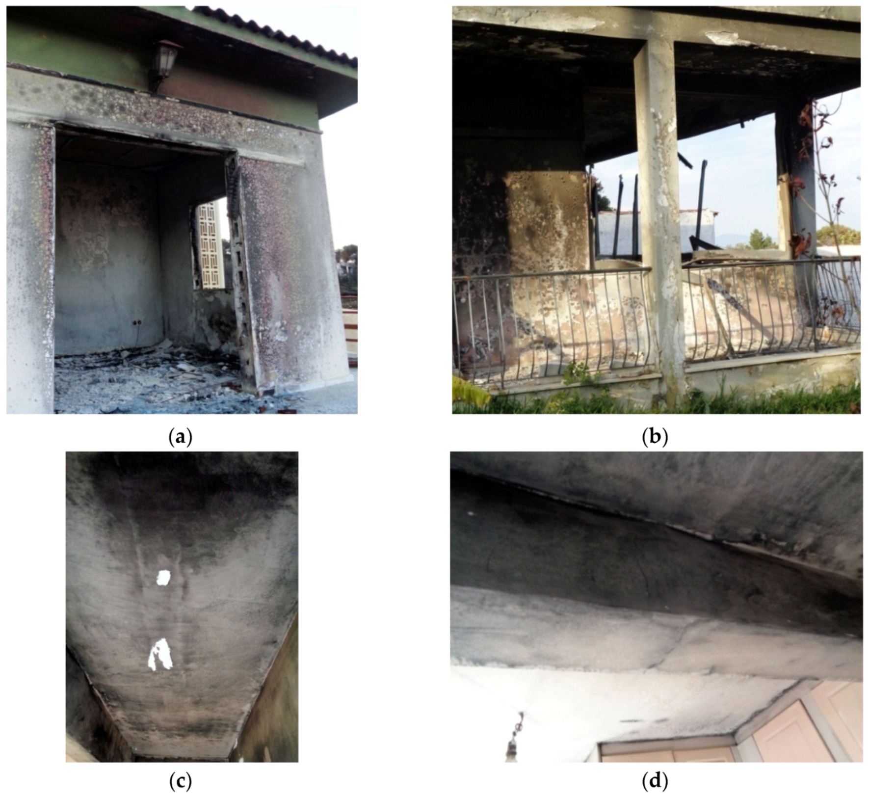
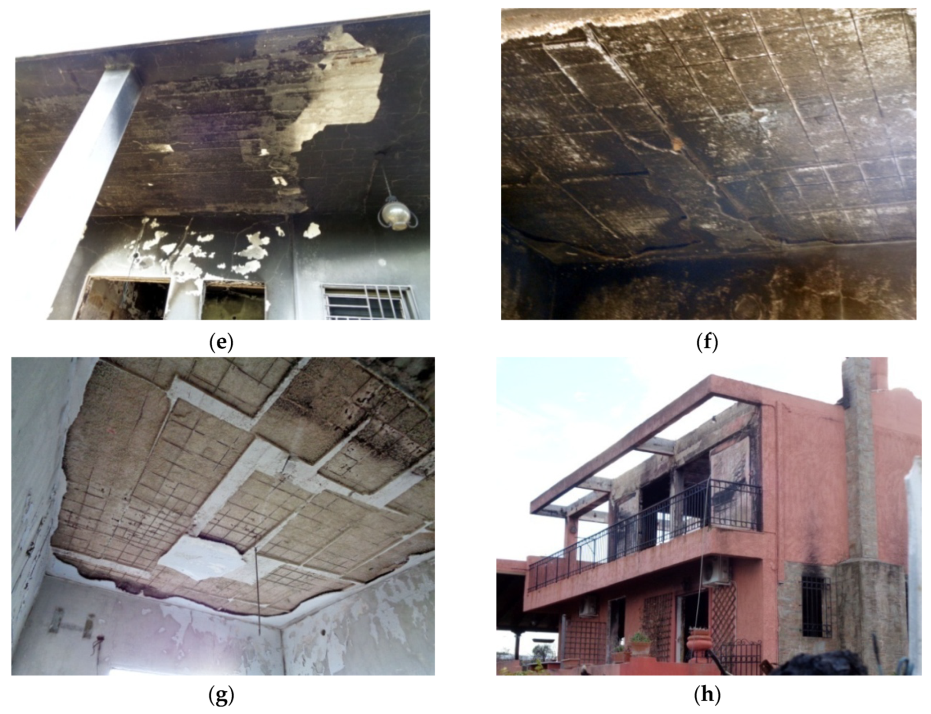
4.2.1. Observed Damage of Reinforced Concrete Buildings

The buildings depicted in Figure 5 consisted of a reinforced concrete frame and brick infill walls. Discoloration of the cement plaster occurred in the walls exposed to fire, especially around the windows (Figure 5a). The different observed colors reveal the temperatures that developed. Aside from the discoloration, more severe damage was observed, including cracks in small-section concrete columns (Figure 5b), the sagging of concrete slabs (Figure 5c), cracks in the middle section of beams (Figure 5d), and spalling of the slab’s plaster (Figure 5e), which in some cases proceeded to the concrete cover of the steel bars, exposing them to high-temperature conditions (Figure 5f,g). Most of the windows were destroyed, and the melting of the frame increased the temperature, as can be observed from the colors around the windows (Figure 5a,h). When the fire entered the house, it burnt everything in its way, leaving standing the frame and the walls of the building. Even though considerable damage occurred, most of the buildings with concrete frames and infill walls were still repairable.

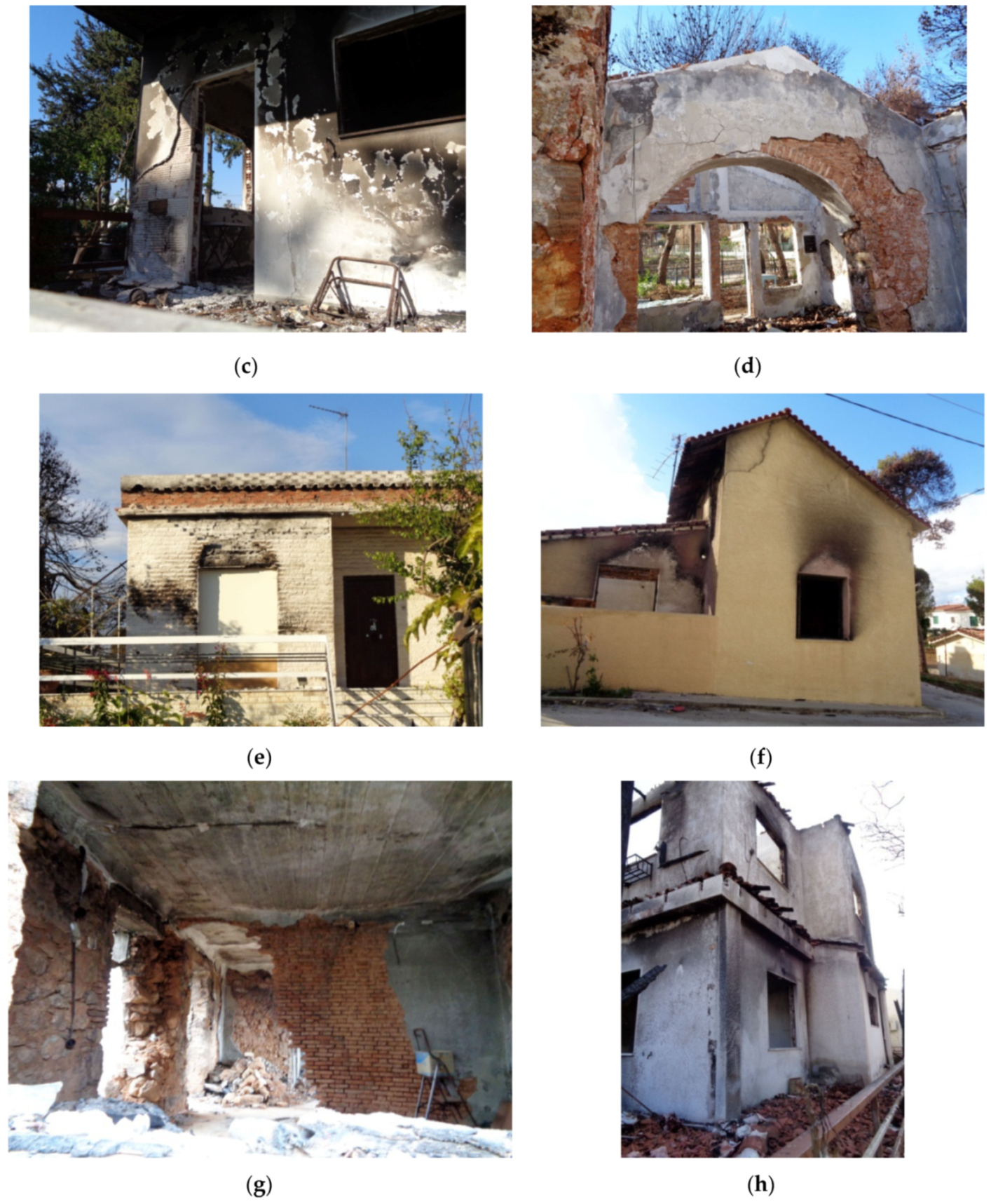
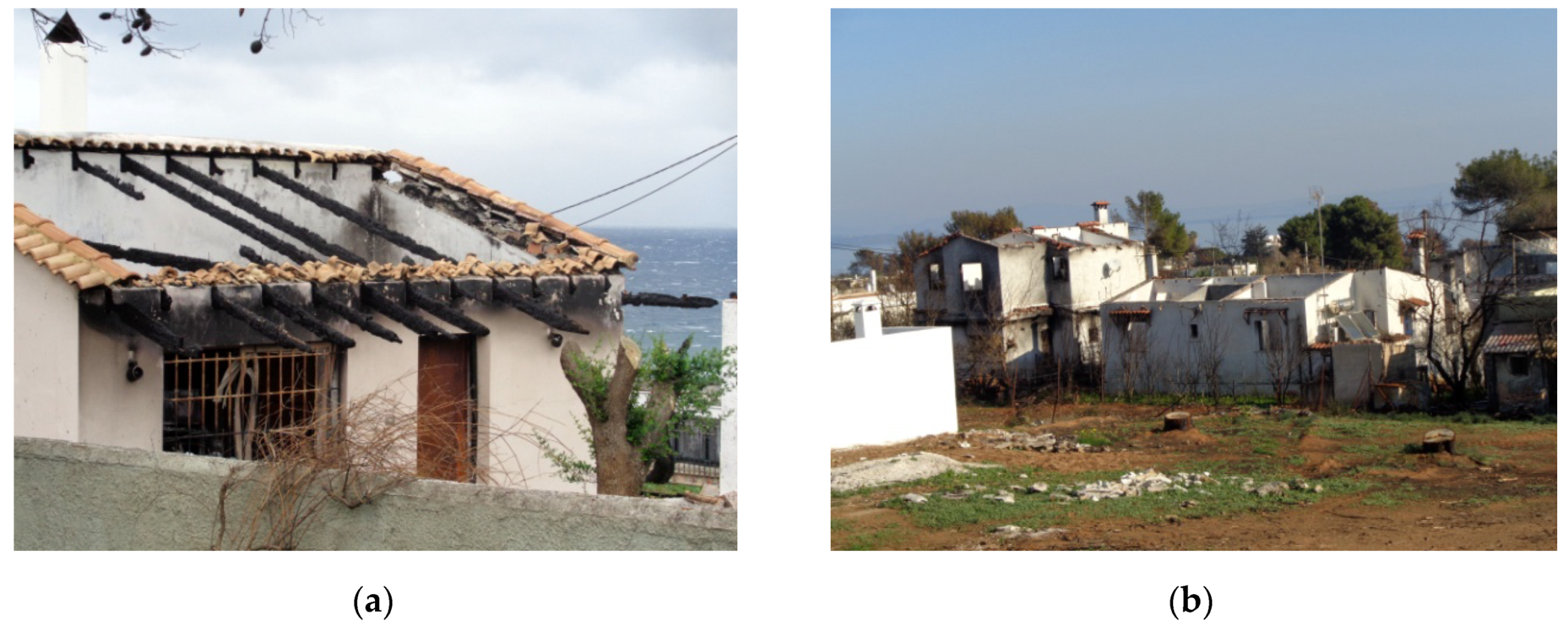
4.2.2. Observed Damage of Masonry Buildings

The houses from masonry in Mati were composed from stone, brick, cement blocks, or a combination of them. Discoloration of the units exposed to fire was observed, especially above the windows (Figure 6a,b). Cracking and peeling were observed in walls covered with paint or plaster (Figure 6c,d). The windows exposed to fire were burnt. Cracks appeared above the windows and below the wooden roof (Figure 6e,f). Some units fell down, destroying part of the masonry walls (Figure 6g). The roofs that were made from wood were burnt (Figure 6h). The pictures show that the windows, the roof, and everything inside the house may have been destroyed, but the walls in most of the buildings were still standing, experiencing damage in the form of cracks above the windows, discoloration, and destruction of the plaster covering the walls.

4.2.3. Observed Damage of Timber Structures

Only a few structures were made solely from wood in Mati. Wood was used mostly as a structural framework in roofs, as a patio cover, and in windows. These parts of the buildings were destroyed when they were exposed to fire (Figure 7).

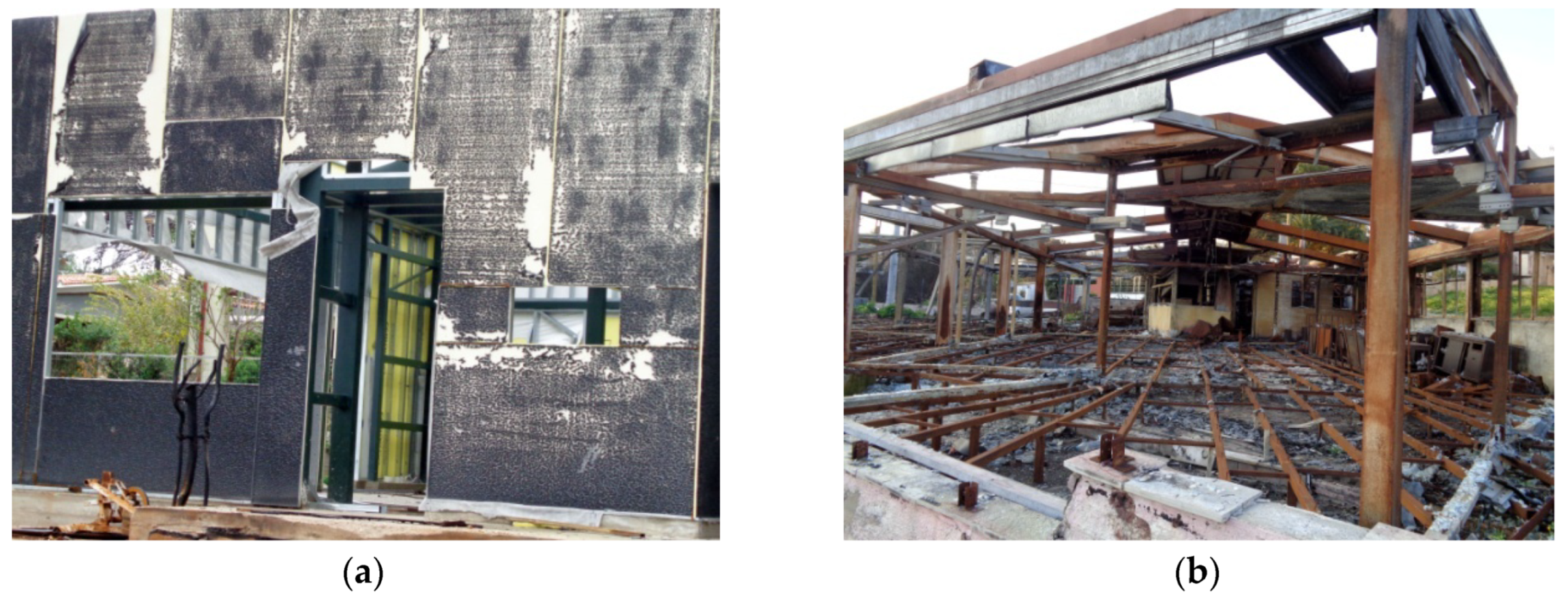
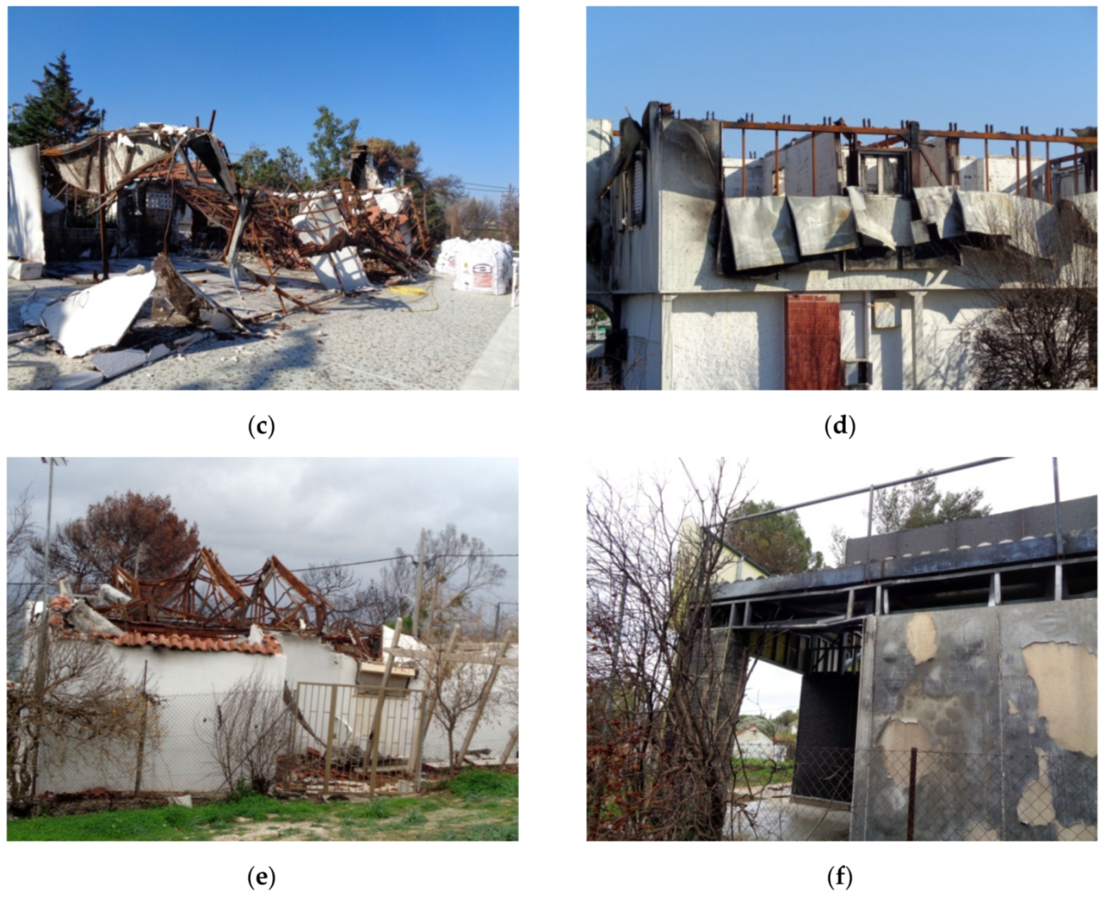
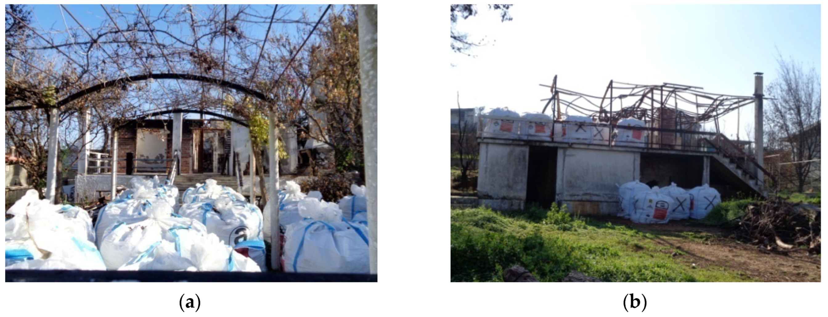
4.2.4. Observed Damage of Buildings with Steel Frames

Few buildings in Mati had a steel frame as a structural form. These buildings were light-weight, with cement boards as infill walls and in some cases metal siding panels with thermal insulation for exterior walls. The strong beams and columns of the buildings either were not affected or exhibited some oxidation (Figure 8a,b). Most of the thin metal members were oxidized and buckled, revealing the temperatures that developed and the prolonged period of time they were exposed to fire (Figure 8c). In some buildings, cement boards with their light wire mesh followed the collapse of the structural form (Figure 8c). In others, the external walls from metal siding panels buckled (Figure 8d). The members of steel roof trusses exposed for a prolonged time to fire exhibited oxidation, severe damage, and buckling (Figure 8e). Some thin aluminum parts in the window frames buckled (Figure 10f).
Asbestos existed in more than 200 buildings in the area exposed to fire (Figure 9). After the fire, the remains were collected and put inside special bags in order to be carried away and deposited in a safe place.
After the fire, a crew of engineers visited all of the buildings, characterizing them (depending on the observed damage) as repairable, nonrepairable, or without any damage. Depending on the characterization, the building was marked with a colored sign. A green sign corresponded to a building without damage, yellow to a building with repairable damage (Figure 10a–c), and red to a building with nonrepairable damage (Figure 10d,e). In some buildings, only one of the floors was characterized as nonrepairable (Figure 10f). Almost half of the buildings were characterized as green, 23% as yellow, and 28% as red.

5. Numerical Analysis

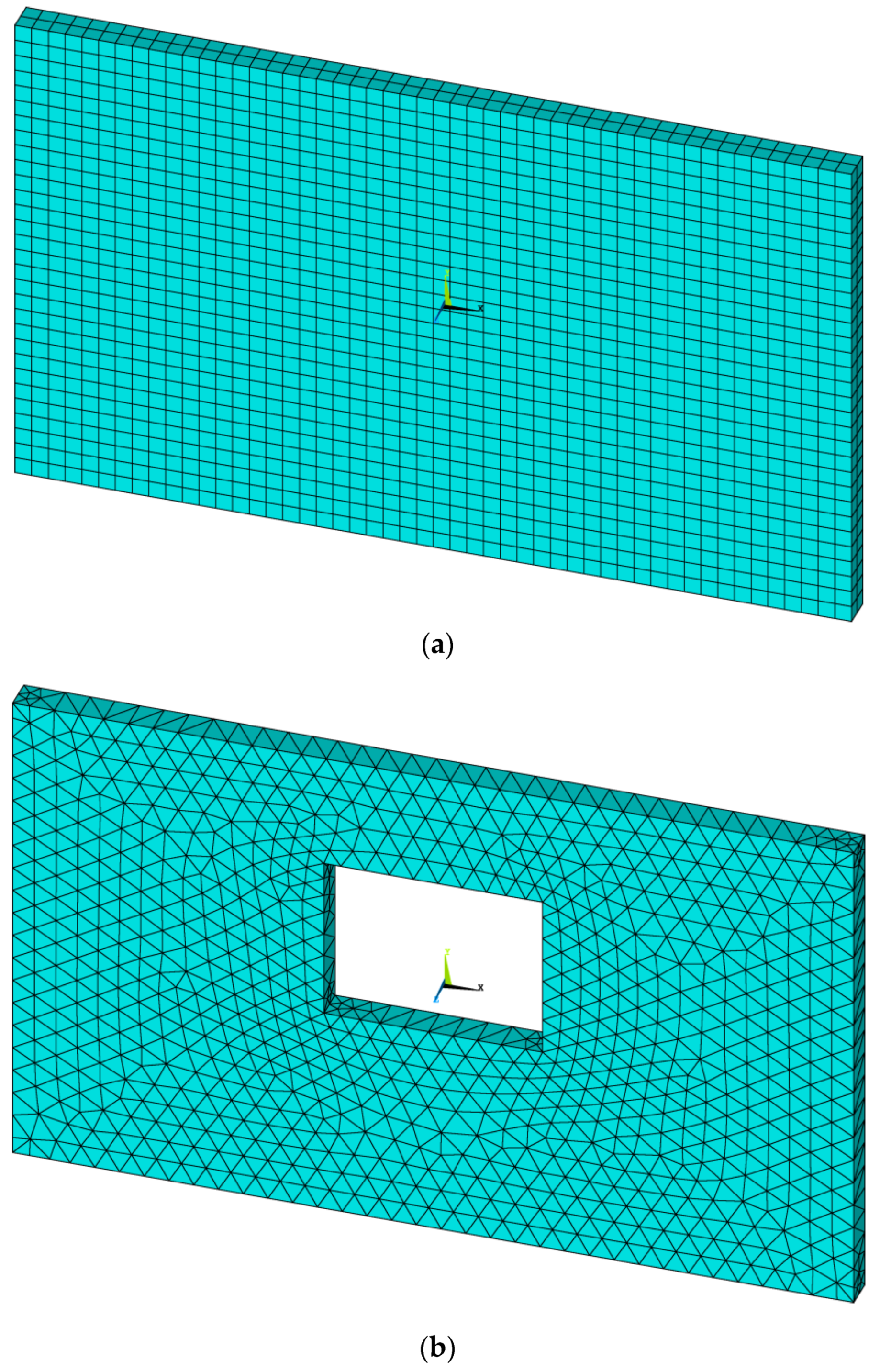
5.1. Numerical Model

A numerical analysis was performed as a supplement to the in situ investigations discussed in the previous sections. The main aim of this analysis was to estimate the temperature distribution in structural subsystems under extreme heat scenarios similar to those experienced during the 2018 Attica region wildfires. The numerical results were compared to field observations in order to evaluate the reliability of the model’s predictions.
Considering the typology of the residential buildings in the area of the case study, we focused our numerical investigation on an analysis of a typical wall panel of dimensions 5 m in length and 3 m in height. Wall thickness was expected to affect the temperature distribution on the nonexposed wall face and was addressed in a parametric manner. Two values were examined, with 0.20 m representing a typical masonry infill and 0.50 m representing the bearing masonry of a medium-rise building.
Moreover, the effect of openings was also included in our numerical investigation, given the fact that structural damage patterns on walls appear to be connected with their presence (or absence). Thus, two different models of 0.20-m-thick wall panels were used in the analysis: W1A represented a “continuous” wall without openings, and W1B represented a window opening of dimensions 1.3 m in length and 1 m in height located at the center of a panel (Figure 11).
A numerical representation of the examined wall panels was derived using ANSYS [21] computer code. The volumes comprising each panel were meshed into respective proper 3-D finite elements (FEs). A solid element with thermal conduction capability was selected. The element was defined by eight nodes and isotropic or orthotropic material thermal properties. It had a single degree of freedom, namely temperature, at each node. A hexahedral, prism-shaped, tetrahedral, or pyramid-shaped element could be formed by properly managing node locations in order to better match the geometry of each problem. The “continuous” wall panel model (W1A) was meshed into 3000 hexahedral elements, whereas prism-shaped elements were more appropriate for a specimen with an opening. In the latter case, the number was increased to 5683 elements as a result of the slightly denser grid that was applied in the area immediately around the opening in order to improve the accuracy of the results. It should be noted that finer meshes were also applicable since the computational load for the solution of such simplified heat transfer problems is rather limited, yielding numerical models manageable from typical personal computers and suitable for use in practical applications.
Thermal conductivity, λc, was identified as the crucial parameter that defines the behavior and the results of the numerical model. As discussed in previous sections, the environment built in the area of the case study is comprised mostly of low- and medium-rise masonry buildings or buildings with reinforced concrete structural systems and masonry infills.
Concrete, cementinius mortars, and typical clay masonry units (bricks) or limestone stone units are the most common materials used. The thermal conductivity of standard concrete reduces as temperature rises. Eurocode 2 [13] provides one upper bound and one lower bound equation for λc with respect to temperature. The lower bound estimation provides values ranging from 1.36 W/m K for a temperature of 0 °C to about 0.60 W/m K for a temperature of 1200 °C. The lowest value is further reduced to 0.50 W/m K in Eurocode 4 [14]. According to Eurocode 6 [15], the thermal conductivity of typical clay masonry units may rise from 0.42 W/m K to about 1.24 W/m K, which represents an upper bound value for temperatures greater than 200 °C. On the other hand, the λc of limestone units ranges from 1.00 W/m K to a highest value of about 4.00 W/m K at 200 °C, but then gradually drops to practically 0 at about 1200 °C. However, the equivalent thermal conductivity of masonry also depends on the λc value of the cementinius mortar, which is similar to that of concrete. Considering the previous discussion, we decided that thermal conductivity should also be addressed in a parametric manner. Two values of λc were considered: 0.50 W/m K, representing a lower bound estimation, and 1.00 W/m K, which is a typical mid-range value associated with the materials used for the construction of the buildings in the area of our case study.

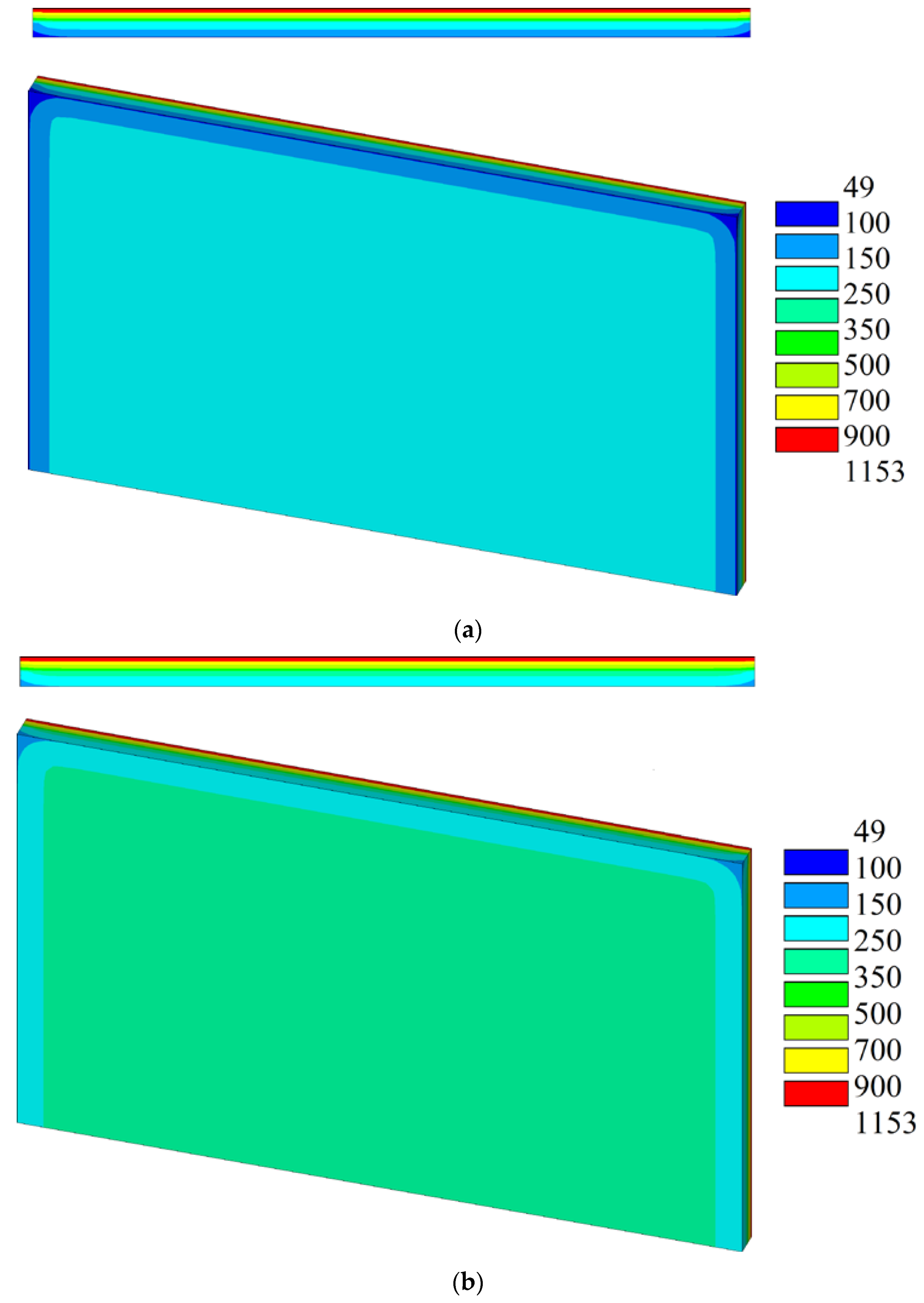
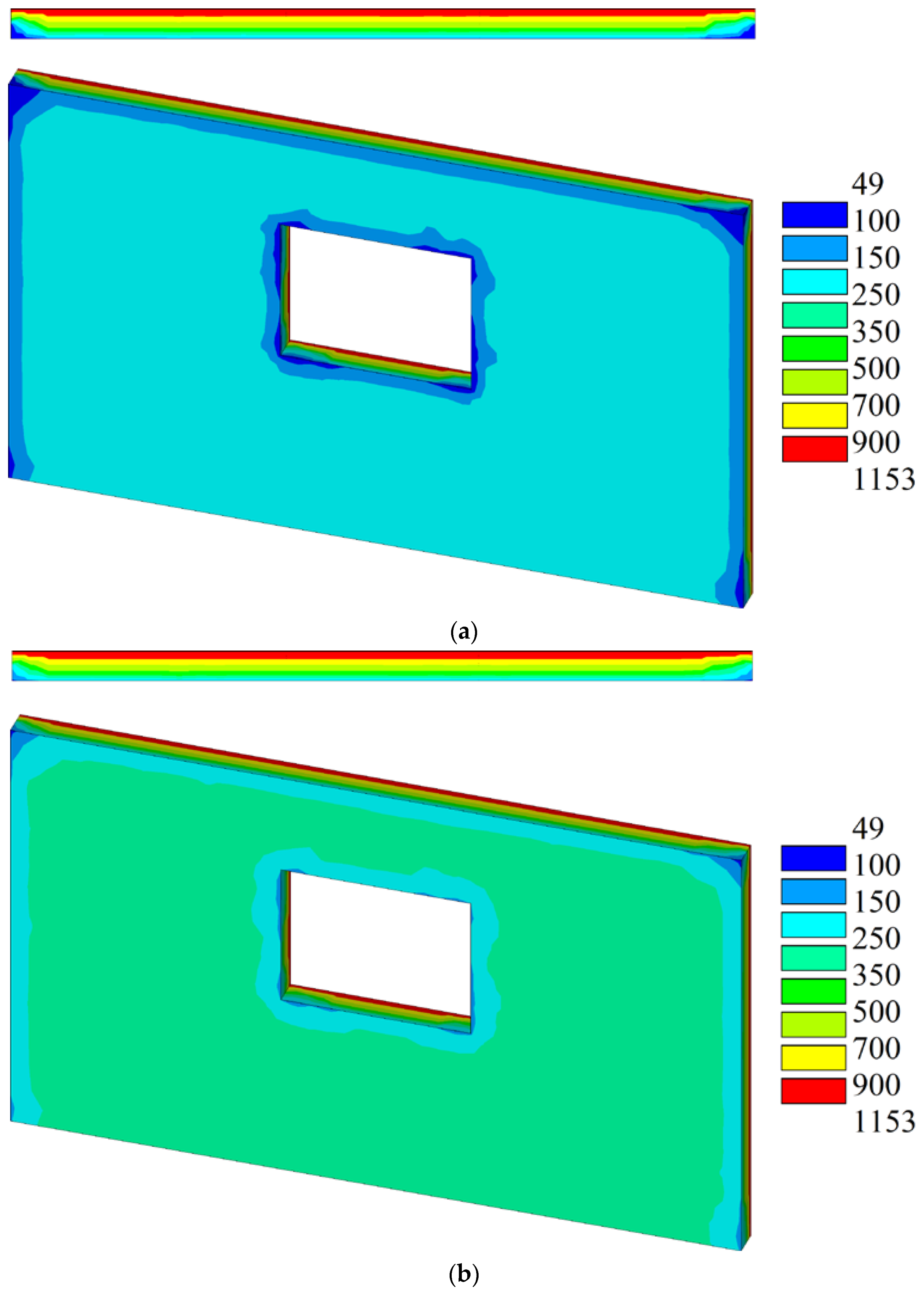
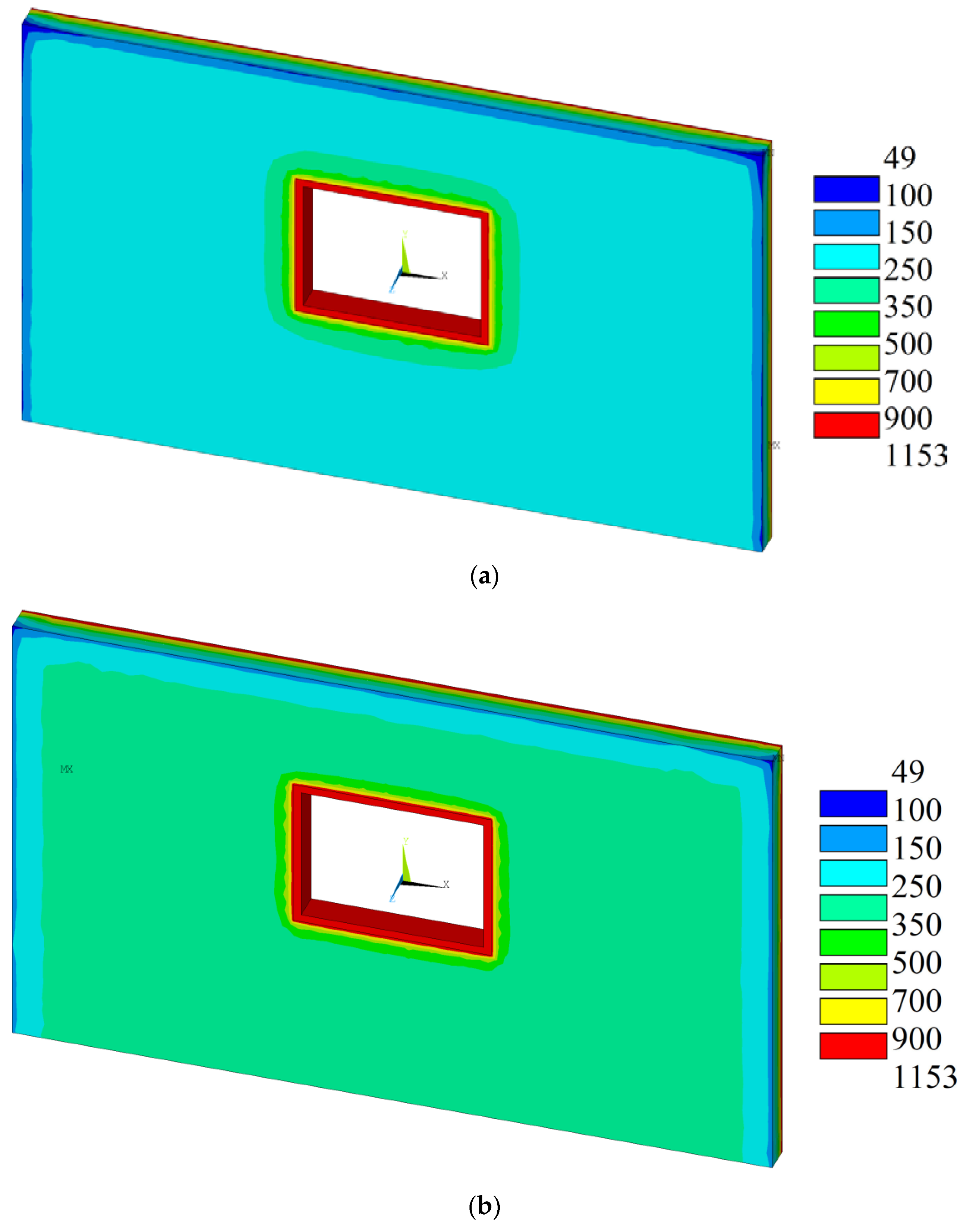
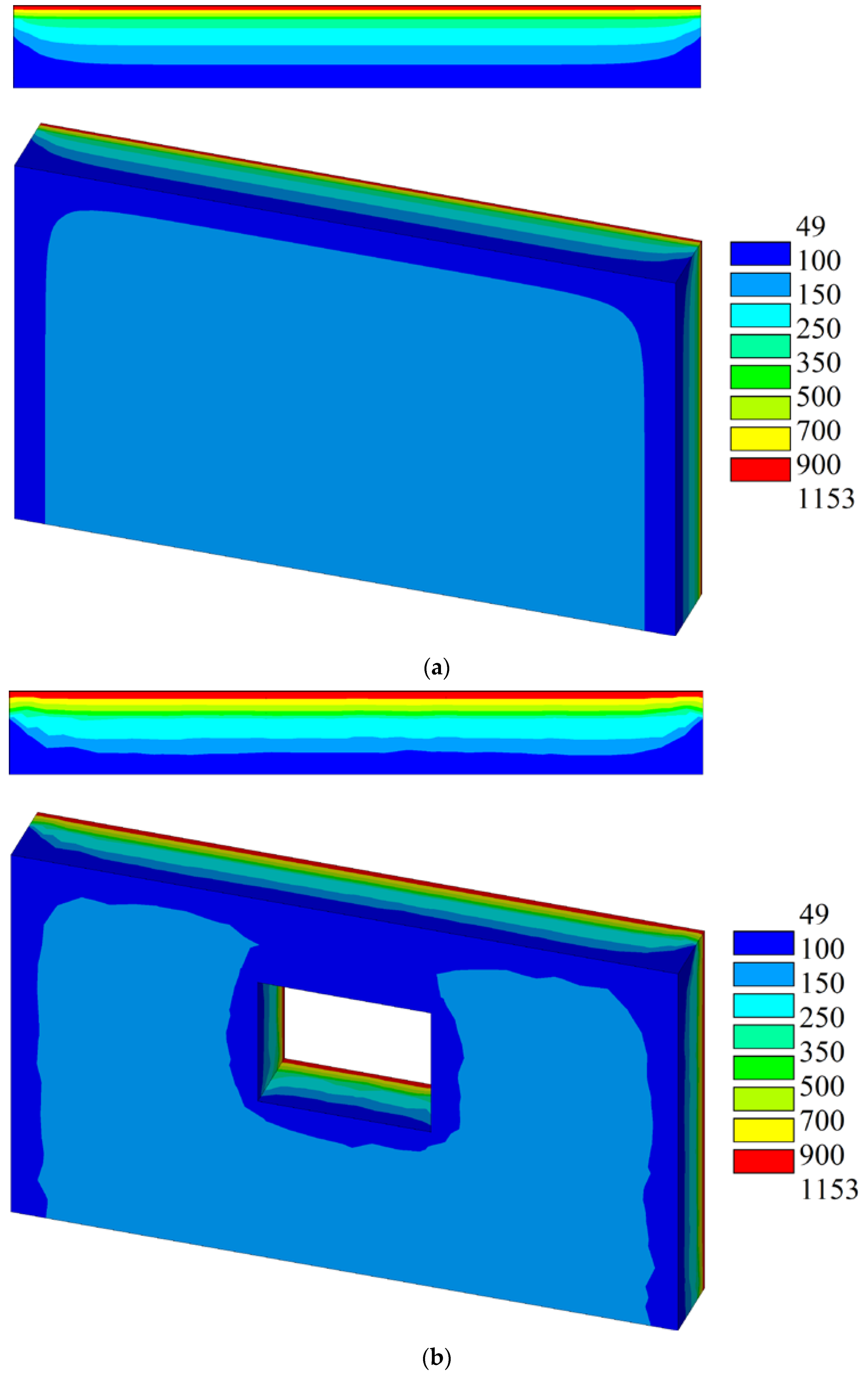
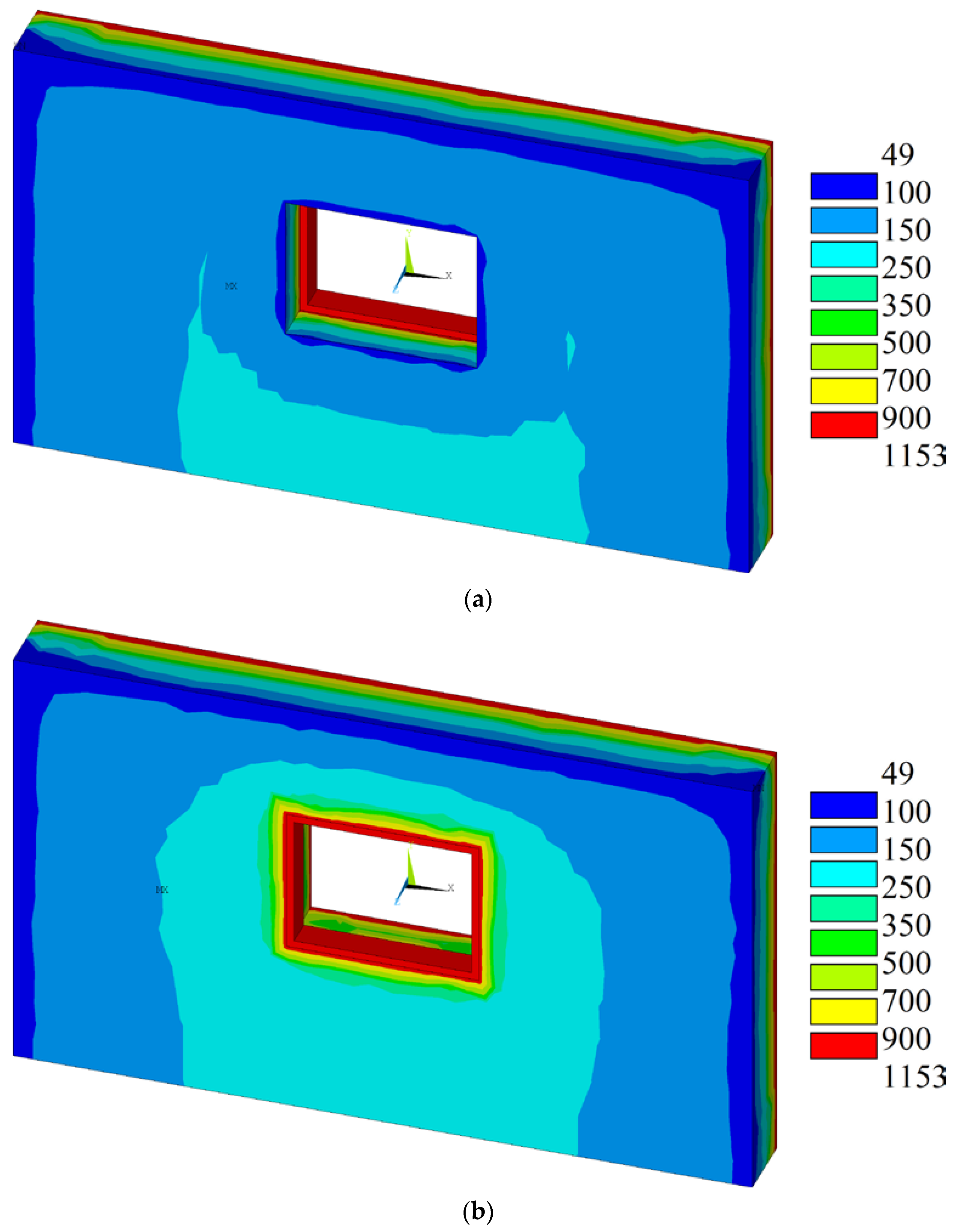
5.2. Numerical Analysis Results and Discussion

Temperature loads were described using a standard ISO 834 fire curve [11] with a total duration of 240 min. The duration was selected considering the severity and extreme temperatures recorded at the actual case study event. For the same reason, one face of the wall model was assumed as uniformly “loaded” with the previously described temperature history. Convection and radiation boundary conditions were defined on all other surfaces of the wall specimens except for the bottom one (which was assumed to be connected to the foundation and the ground). Typical values for the respective coefficients were selected according to the literature [22,23,24]. The surface convection coefficient was set equal to 20 Wm−2 °C−1, while emissivity related to the wall surfaces was adopted as εm = 0.7.
The temperature gradients on the nonexposed face and a section of the wall for the W1A and W1B models are presented in Figure 12 and Figure 13, respectively.
As can be seen in both figures, the use of the lower value of λc led to relatively low temperature values (< 200 °C) on the nonexposed face. This was not consistent with the in situ observations of extensive coloration and structural damage related to high temperature values on both exposed and nonexposed faces of walls. The use of λc = 1.00 W/m K significantly improved the results, leading to temperatures up to about 400 °C on the nonexposed face of the model. Thus, we may conclude that the latter value of thermal conductivity was more appropriate for the numerical investigation of the problem. The previous observations were consistent with results found in similar research efforts (e.g., References [22,23,24,25]). However, as shown in Figure 13, both numerical models appeared to misinterpret the effect of openings. Lower temperatures were calculated in their immediate areas, which would indicate that openings are actually “stress relief” zones, and as a result, no significant structural damage should be expected close to them. Obviously this contradicted the previously discussed field observations (e.g., Figure 6e).
In order to further investigate the reason for the contradiction between the numerical results and the field observations, a more accurate representation of an actual wall panel was employed. In this case, the window frame was properly included in the numerical model. Window frames of typical residential buildings are usually constructed from aluminum or, in rare cases, steel. Aluminum has a significantly larger thermal conductivity, namely about 200 W/m K, than masonry does. Hence, the thermal behavior of the window frame differs greatly from that of the surrounding wall. In order to properly analyze the behavior of this “dual system”, both its components should be carefully included in a numerical model.
Window frames were included in the numerical model as a separate volume that was subsequently meshed to respective 3-D FEs with properties representative of the frame material (λc = 200 W/m K). The heat transfer between the separate volumes was achieved by using proper nodal constraints for the frame–masonry interfaces. Indicative results from the analysis of the more detailed model, including the window frame, are presented in Figure 14.
The numerical results indicated that the model identified the effect of openings, as it properly calculated the variation and higher values of temperature that may lead to concentrated structural damage in the immediate area of wall openings, as was observed in the field.
Finally, Figure 15 presents the results for W2A and W2B models. These were similar to W1A and W1B, respectively, with the wall thickness increased to 0.50 m.
Thermal conductivity was considered equal to 1.00 W/m K in both cases. The analysis results indicated that even in the extreme temperature scenario that was applied, relatively low values of temperature (< 150 °C) were expected in the nonexposed wall face. This may be possible in cases of very thick stone masonry. The results were improved when the window frame was properly modeled, as shown in Figure 16.
In this case, the numerical findings suggested that the location of the window frame may also affect the temperature distribution and, as a result, the expected structural damage. As shown in Figure 16b, when the window frame was closer to the nonexposed face and the fire reached it, a higher temperature in its immediate area was possible, leading to extensive structural damage on the nonexposed face of thick masonry. This was consistent with some of the field observations discussed in the previous sections of the present article.
Based on our initial findings, we believe that a more extensive numerical analysis program considering a wider range of alternative values of thermal conductivity may shed more light for the case of thick stone masonry.
In future investigations, a wider range of values of thermal conductivity will be considered for thick masonry. In addition, the thermal and mechanical response of a building with a concrete frame with brick infill walls and one with load bearing masonry walls and a timber roof exposed to fire will be analyzed numerically. The obtained results will be compared to the observed damage to identify the parameters that most influence response in the case of fire.

6. Conclusions

The effects of extreme temperatures on different construction materials were outlined. The severity and the extent of damage in buildings that was caused by one of Greece’s deadliest wildfires (occurring in July 2018) were presented. Observations of the damage that occurred in the buildings exposed to this wildfire demonstrated the resistance of concrete, steel, masonry, and timber structures to extreme heat conditions. As expected, concrete and masonry structures exhibited a superior performance to steel and timber.
A finite element analysis on the thermal response of a typical wall panel under extreme heat conditions was performed by varying the geometry of the wall panel and its thermal conductivity. The analysis showed the following:
  • When the walls were exposed to extreme heat conditions and damage was observed, the highest thermal conductivity value recommended by Eurocode better represented the temperatures developed;
  • The edges of the nonexposed faces of the wall panels were least affected by the extreme heat conditions;
  • When wall openings were included in the analysis, they had to be considered together with their window frame in order to properly identify the temperatures that developed;
  • The thickness of the wall panel played an important role in temperature distribution. The larger the thickness was, the lower the temperatures were that developed across the wall panel;
  • The location of the window frame played an important role in thick masonry. When it was closely, the exposed face had a small effect on the temperatures that developed across the window and on the nonexposed face. The opposite occurred when the window frame was closer to the nonexposed face and the fire reached it. In the last case, the area around the window was affected the most.
It is observed that even simple FE models with carefully selected material thermal properties can provide useful information on the temperature distribution in structural members that can be directly linked to damage from wildfires.
The results from such a numerical analysis can be used as the basis for design optimization or the rehabilitation of structural damage after extreme wildfire events similar to the one discussed in the present article. Simple guidelines can be used to reduce/prevent structural damage in buildings exposed to fire.

Author Contributions

Conceptualization, A.P.; Formal Analysis, D.K.B.; Software, D.K.B.; Visualization, A.P.; Writing-Review-Editing, A.P. and D.K.B.

Funding

This research received no external funding.

Conflicts of Interest

The authors declare no conflicts of interest.

References

  1. Chowdary, V.; Gupta, M.K. Intelligent communication, control devices. In Advances in Intelligent Systems and Computing; Springer: Singapore, 2018; pp. 1111–1117. [Google Scholar]
  2. Dimitrakopoulos, A.; Gogi, C.; Stamatelos, G.; Mitsopoulos, I. Statistical analysis of the fire environment of large forest fires (> 1000 ha) in Greece. J. Environ. Stud. 2011, 20, 327–332. [Google Scholar]
  3. Xanthopoulos, G. Factors affecting the vulnerability of houses to wildland fire in the Mediterranean region. In Proceedings of the International Workshop Forest Fires in the Wildland-Urban Interface and Rural Areas in Europe, Athens, Greece, 15–16 May 2003. [Google Scholar]
  4. Buchanan, A.H.; Abu, A.K. Structural Design for Fire Safety, 2nd ed.; Wiley: Hoboken, NJ, USA, 2017. [Google Scholar]
  5. Porterie, B.; Consalvi, J.-L.; Loraud, J.-C.; Giroud, F.; Picard, C. Dynamics of wildland fires and their impact on structures. Combust. Flame 2007, 149, 314–328. [Google Scholar] [CrossRef]
  6. Bailey, C.G.; Moore, D.B. The behaviour of full-scale steel framed buildings subject to compartment fires. Struct. Eng. 1999, 7, 15–21. [Google Scholar]
  7. Lamont, S.; Lane, B.; Flint, G. Behavior of Structures in Fire and Real Design—A case Study. J. Fire Prot. Eng. 2006, 16, 5–35. [Google Scholar] [CrossRef]
  8. Foster, S.; Chladna, M.; Hsieh, C.; Burgess, I.; Plank, R. Thermal and structural behaviour of a full scale composite building subject to a severe compartment fire. Fire Saf. J. 2007, 42, 183–199. [Google Scholar] [CrossRef]
  9. Wald, F.; Simoes da Silva, L.; Moore, D.B.; Lennon, T.; Chladna, M.; Santiago, A.; Benes, M.; Borges, L. Experimental behaviour of a steel structure under natural fire. Fire Saf. J. 2006, 41, 509–522. [Google Scholar] [CrossRef]
  10. Butler, B.W. Characterization of convective heating in full scale wildland fires. In Proceedings of the VI International Conference on Forest Fire Research, Coimbra, Portugal, 15–18 November 2010; Viegas, D.X., Ed.; Miscellaneous Publication: Washington, DC, USA, 2010. [Google Scholar]
  11. ISO 834-1. Fire-Resistance Tests—Elements of Building Construction, Part 1: General Requirements; International Organization for Standardization: Geneva, Switzerland, 1999. [Google Scholar]
  12. Technical Chamber of Greece and National Technical University of Athens. Practical Guide for the Evaluation of Load Bearing Capacity and Structural Repairs on Small Concrete and Masonry Buildings after Fires; Technical Chamber of Greece and National Technical University of Athens: Athens, Greece, 2008. (In Greek) [Google Scholar]
  13. EN 1992-1-2. Eurocode 2—Design of Concrete Structures—Part 1-2: General Rules Structural Fire Design; European Committee for Standardization (CEN): Brussels, Belgium, 2004. [Google Scholar]
  14. EN 1994-1-2. Eurocode 4—Design of Composite Steel and Concrete Structures—Part 1-2: General Rules—Structural Fire Design; European Committee for Standardization (CEN): Brussels, Belgium, 2005. [Google Scholar]
  15. EN 1996-1-2. Eurocode 6—Design of Masonry Structures—Part 1-2: General Rules—Structural Fire Design; European Committee for Standardization (CEN): Brussels, Belgium, 2005. [Google Scholar]
  16. Vassart, O.; Zhao, B.; Cajot, L.G.; Robert, F.; Meyer, U.; Frangi, A. JRC Science and Policy Reports Eurocodes: Background & Applications Structural Fire Design; Report EUR 26698 EN; Publications Office of the European Union: Brussels, Belgium, 2014. [Google Scholar]
  17. Kiute, L.M.; Mang’uriu, G.N.; Mulu, P. Effects on flexural strength of reinforced concrete beam subjected to fire. Civ. Environ. Res. 2014, 6, 36–45. [Google Scholar]
  18. Comsa, T. Spalling Mechanism in Concrete Exposed to Elevated Temperatures. Master’s Thesis, Aalborg University, Aalborg, Denmark, 2013. [Google Scholar]
  19. Gomez-Heras, M.; Fort, R. Impact of fire on stone-built heritage. An overview. J. Archit. Conserv. 2009, 15, 47–58. [Google Scholar] [CrossRef]
  20. Buchanan, A.H.; Ostman, B.; Frangi, A. Fire resistance of timber structures. In International Journal of Standards; NIST Special Publication 1188; National Institute of Standards and Technology: Washington, DC, USA, 2014. [Google Scholar]
  21. ANSYS Inc. ANSYS Mechanical APDL, Computer Software; ANSYS Inc.: Canonsburg, PA, USA, 2014. [Google Scholar]
  22. Dzolev, I.M.; Cvetkovska, M.J.; Ladinovic, D.Z.; Radonjanin, V.S. Numerical analysis on the behaviour of reinforced concrete frame structures in fire. Comput. Concr. 2018, 21, 637–647. [Google Scholar]
  23. Nguyen, T.D.; Meftah, F.; Chammas, R.; Mebarki, A. The behaviour of masonry walls subjected to fire: Modelling and parametrical studies in the case of hollow burnt-clay bricks. Fire Saf. J. 2009, 44, 629–641. [Google Scholar] [CrossRef]
  24. Nguyen, T.D.; Meftah, F. Behavior of hollow clay masonry walls during fire. Part 2: 3D finite element modeling and spalling assessment. Fire Saf. J. 2014, 66, 35–45. [Google Scholar] [CrossRef]
  25. Du, H.; Hu, X.; Zhang, B.; Minli, Y. Numerical simulation on behaviour of timber-concrete composite beams in fire. In IOP Conference Series: Earth and Environmental Science; IOP Publishing Ltd: Bristol, UK, 2017; p. 012148. [Google Scholar]
Figure 1. Satellite picture of the areas affected by the fire (from Google Maps).
Buildings 09 00171 g001
Figure 2. Satellite picture of Mati before the fire occurrence (from Google Maps).
Buildings 09 00171 g002
Figure 3. Pictures of Mati after the fire: (a) Coastal area; (b) narrow path leading toward the sea.
Buildings 09 00171 g003
Figure 4. Pictures of Mati the day after the fire (a) forest area (b) damaged buildings and vehicles.
Buildings 09 00171 g004
Figure 5. Pictures showing damage that occurred in reinforced concrete frame buildings and infill walls after the wildfire in Mati: (a,h) discoloration around openings; (b,d) cracking on concrete members; (c) sagging of slabs; (eg) spalling of concrete cover.
Buildings 09 00171 g005aBuildings 09 00171 g005b
Figure 6. Photographs of damage in masonry buildings after the wildfire in Mati: (a,b) discoloration of exposed surfaces; (cf) cracking of walls; (g) extensive damage; (h) destroyed wooden roof.
Buildings 09 00171 g006aBuildings 09 00171 g006b
Figure 7. (a,b) Photographs presenting damage that occurred in wooden roofs after the wildfire in Mati.
Buildings 09 00171 g007
Figure 8. Photographs depicting damage that occurred in buildings with a steel frame after the wildfire in Mati: (a,b) relatively unaffected strong members; (c) corrosion and buckling of thin metal members; (d) buckling of metal panels; (e) severe damage of trusses; (f) buckling of aluminum frames.
Buildings 09 00171 g008aBuildings 09 00171 g008b
Figure 9. (a,b) Pictures of the remains of buildings containing asbestos, which was enclosed in special bags.
Buildings 09 00171 g009
Figure 10. Pictures of buildings characterized as repairable (ac), non-repairable (d,e), or with a nonrepairable upper floor (f).
Buildings 09 00171 g010aBuildings 09 00171 g010b
Figure 11. Model layout: (a) W1A; (b) W1B wall specimens.
Buildings 09 00171 g011
Figure 12. Analysis results for the W1A specimen and two values of material thermal conductivity: (a) 0.50 W/m K; (b) 1 W/m K.
Buildings 09 00171 g012
Figure 13. Analysis results for the W1B specimen and two values of material thermal conductivity: (a) 0.50 W/m K; (b) 1 W/m K.
Buildings 09 00171 g013
Figure 14. Analysis results for the W1B specimen, including an aluminum window frame, and considering (a) 120 min and (b) 240 min of exposure.
Buildings 09 00171 g014
Figure 15. Analysis results for (a) W2A and (b) W2B specimens (material thermal conductivity 1 W/m K).
Buildings 09 00171 g015
Figure 16. Analysis results for the W2B specimen, including an aluminum window frame, close to (a) the exposed and (b) nonexposed face and considering 240 min of exposure.
Buildings 09 00171 g016

