Ultimate Flexural Capacity of Reinforced Concrete Elements Damaged by Corrosion


Abstract
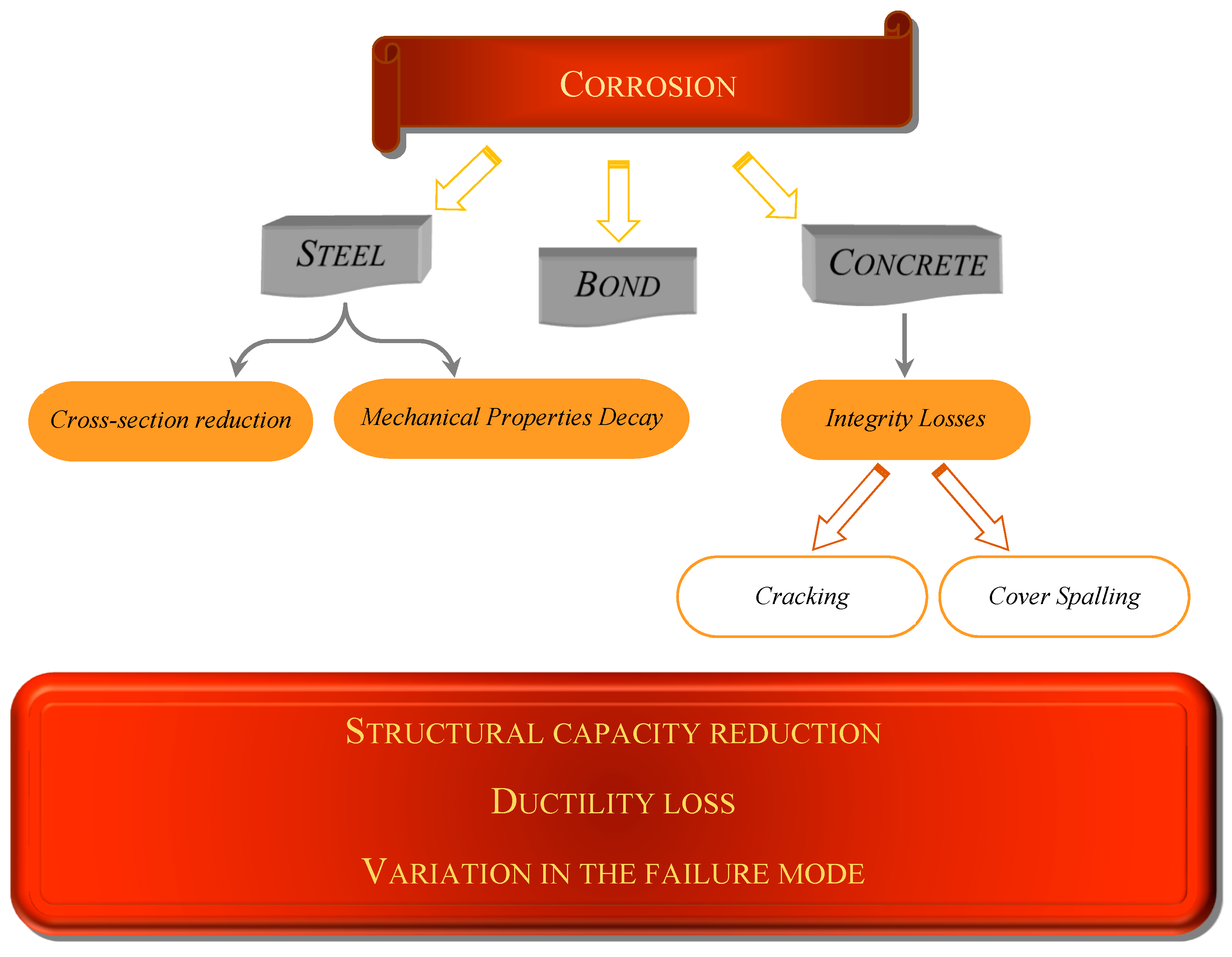
:1. Introduction
2. The Corroded Element with Flexure: Numerical Modeling
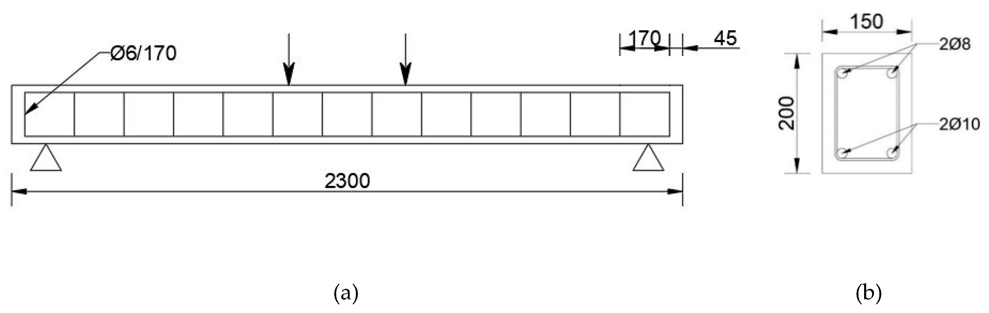
2.1. Selected Experimental Case Study
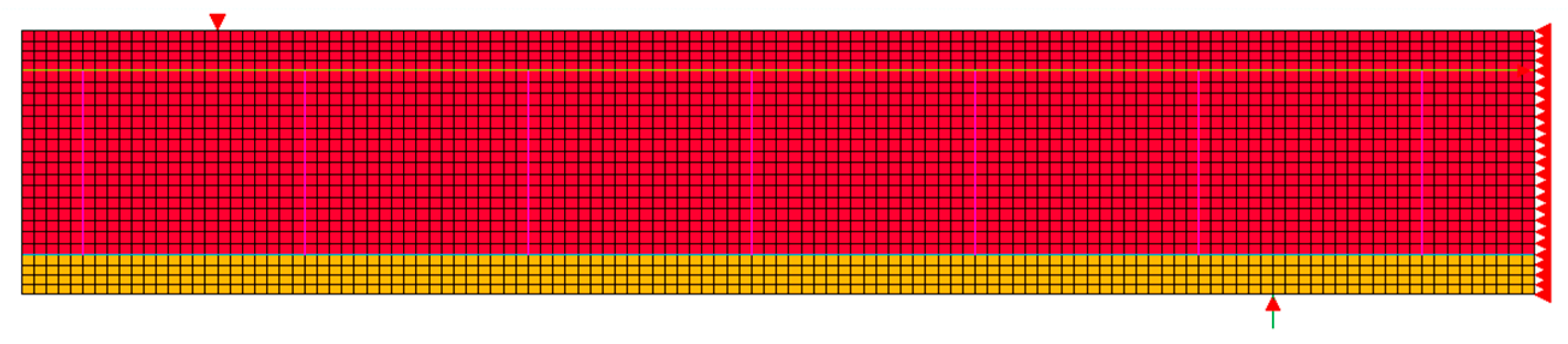
2.2. FE Analysis and Material Properties
2.3. Bond–Slip Model
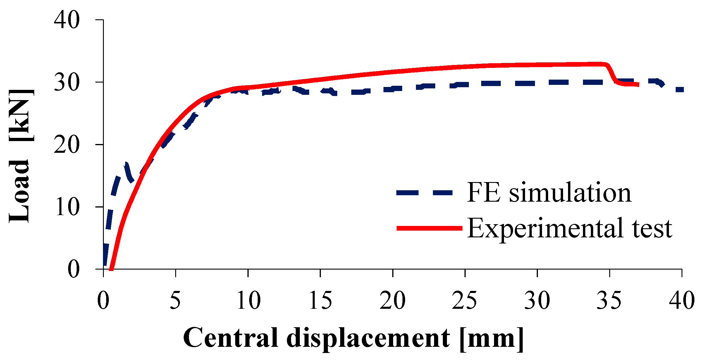
2.4. Comparison between the Numerical and the Experimental Results
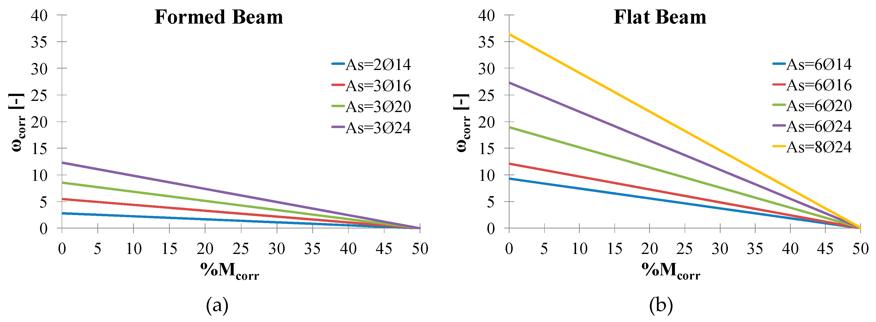
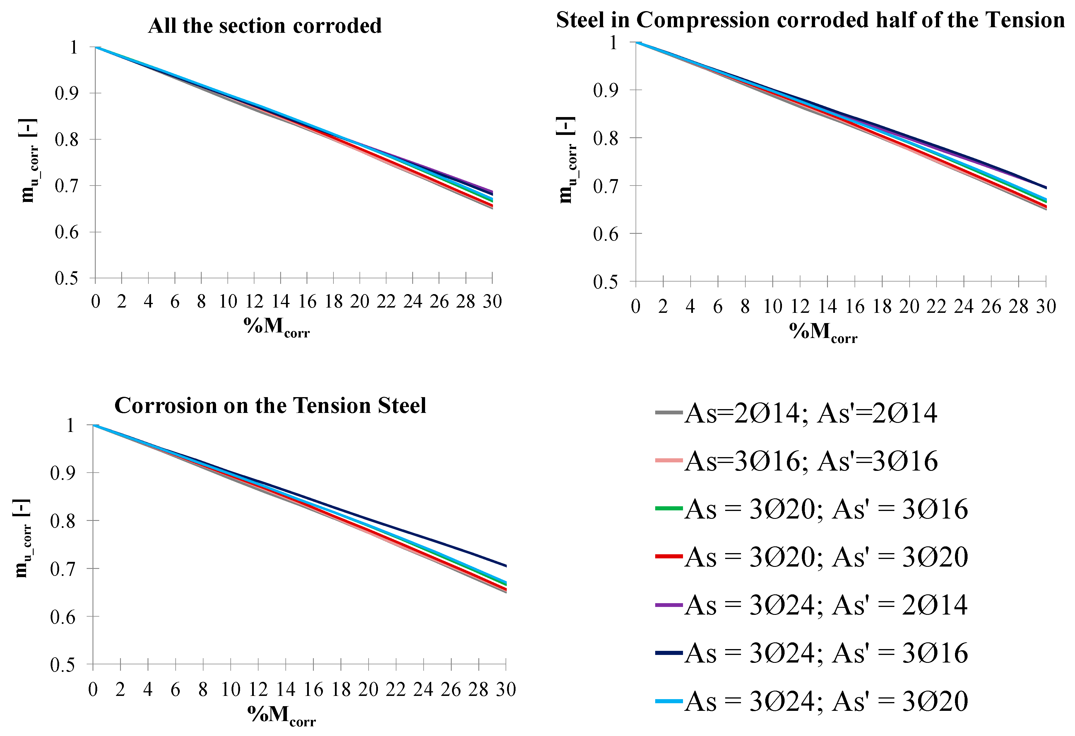
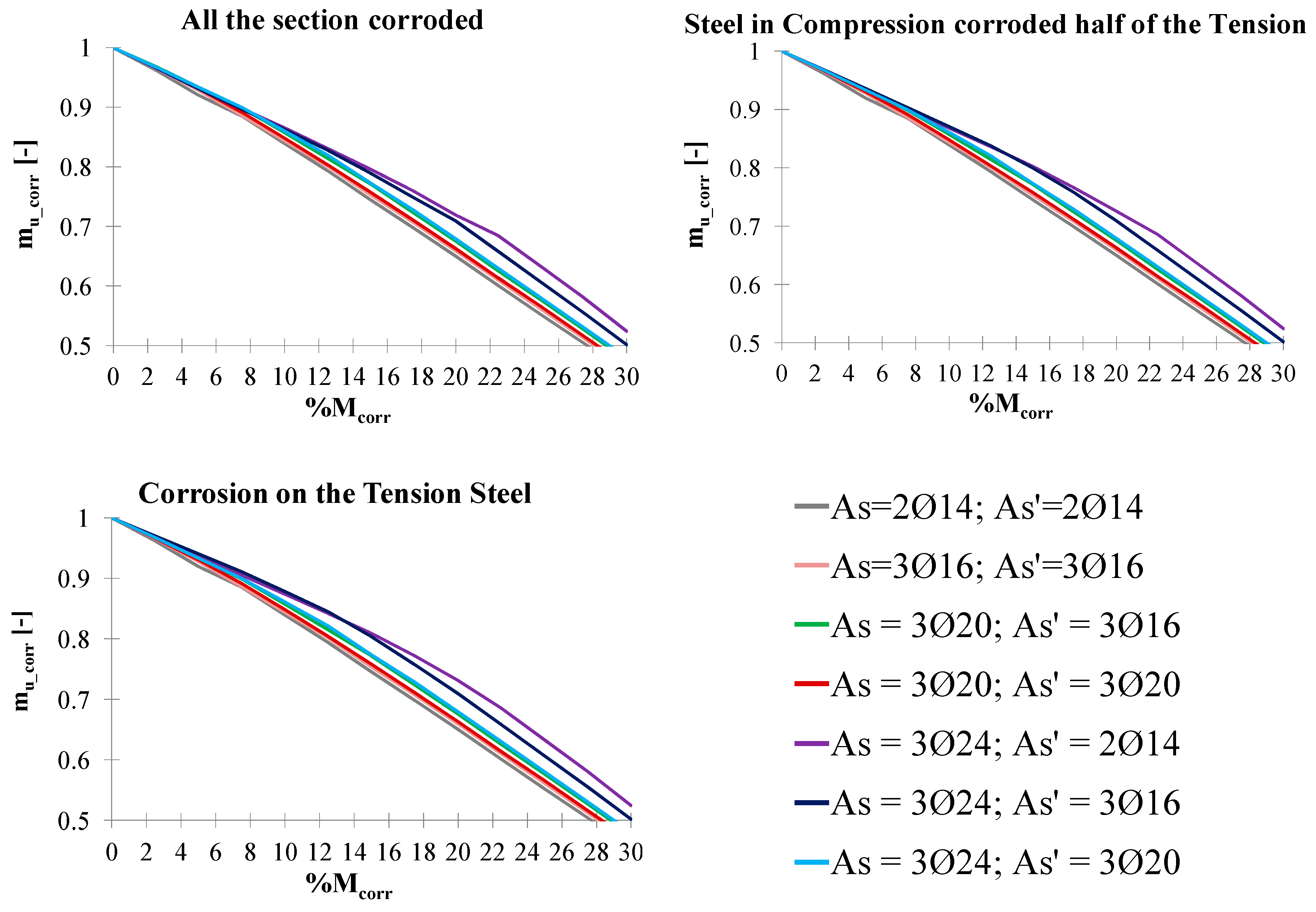
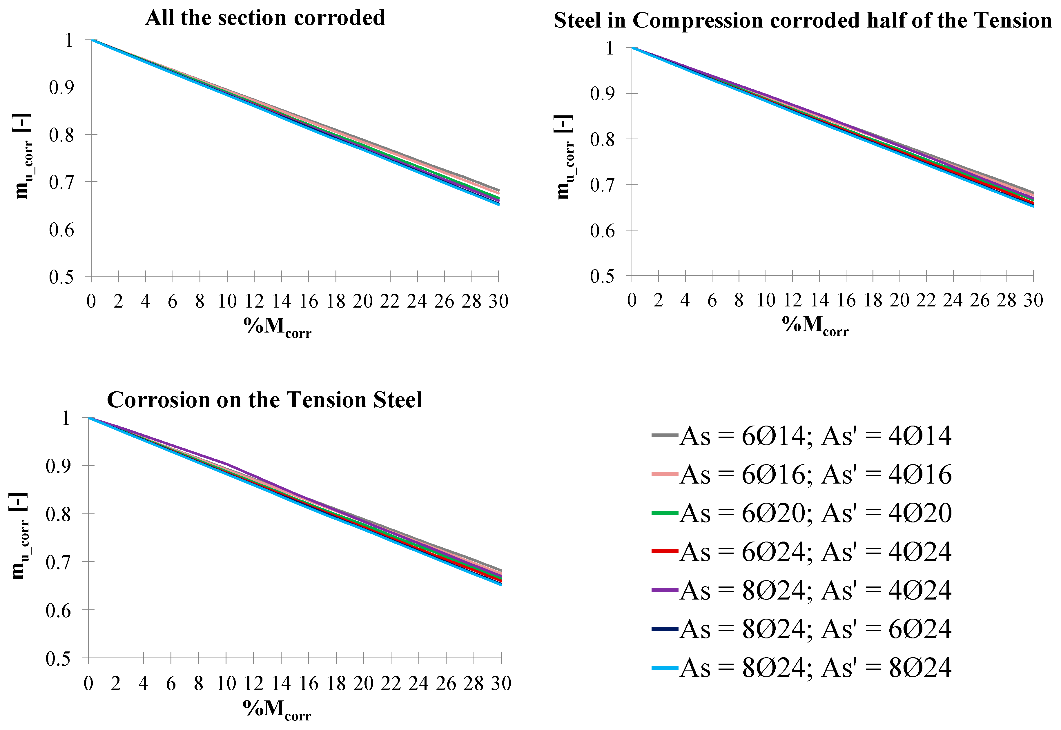
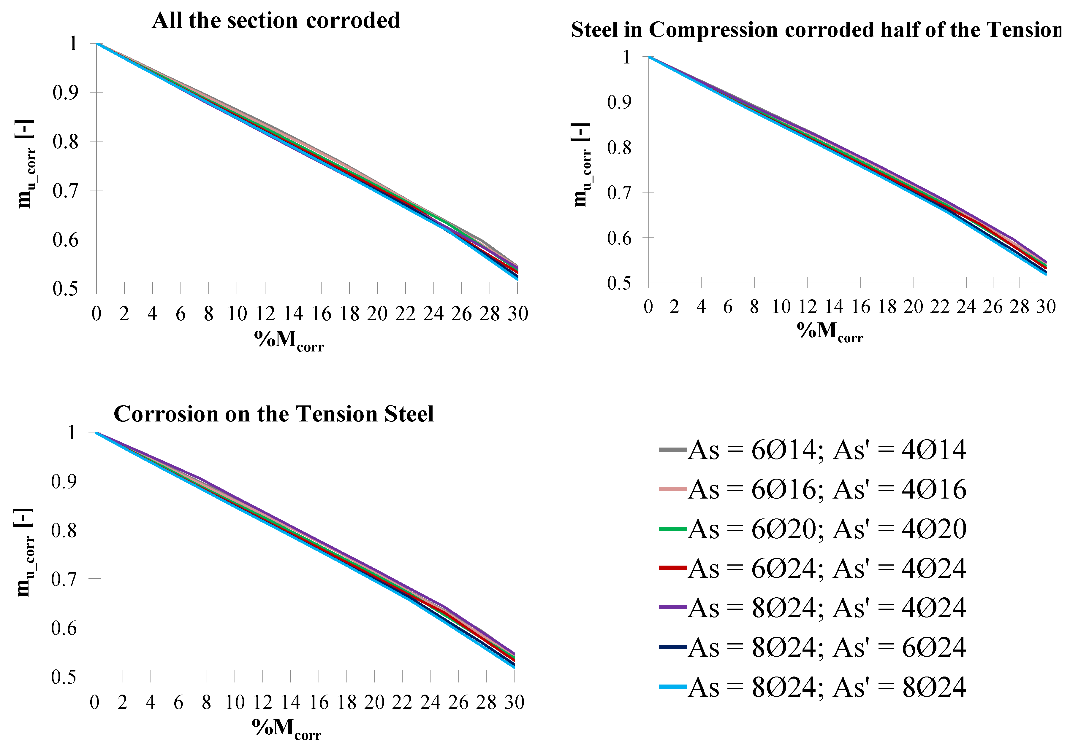
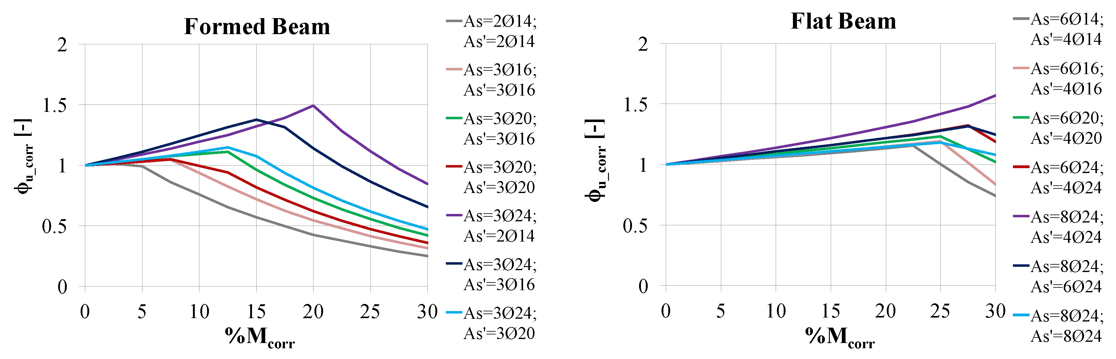
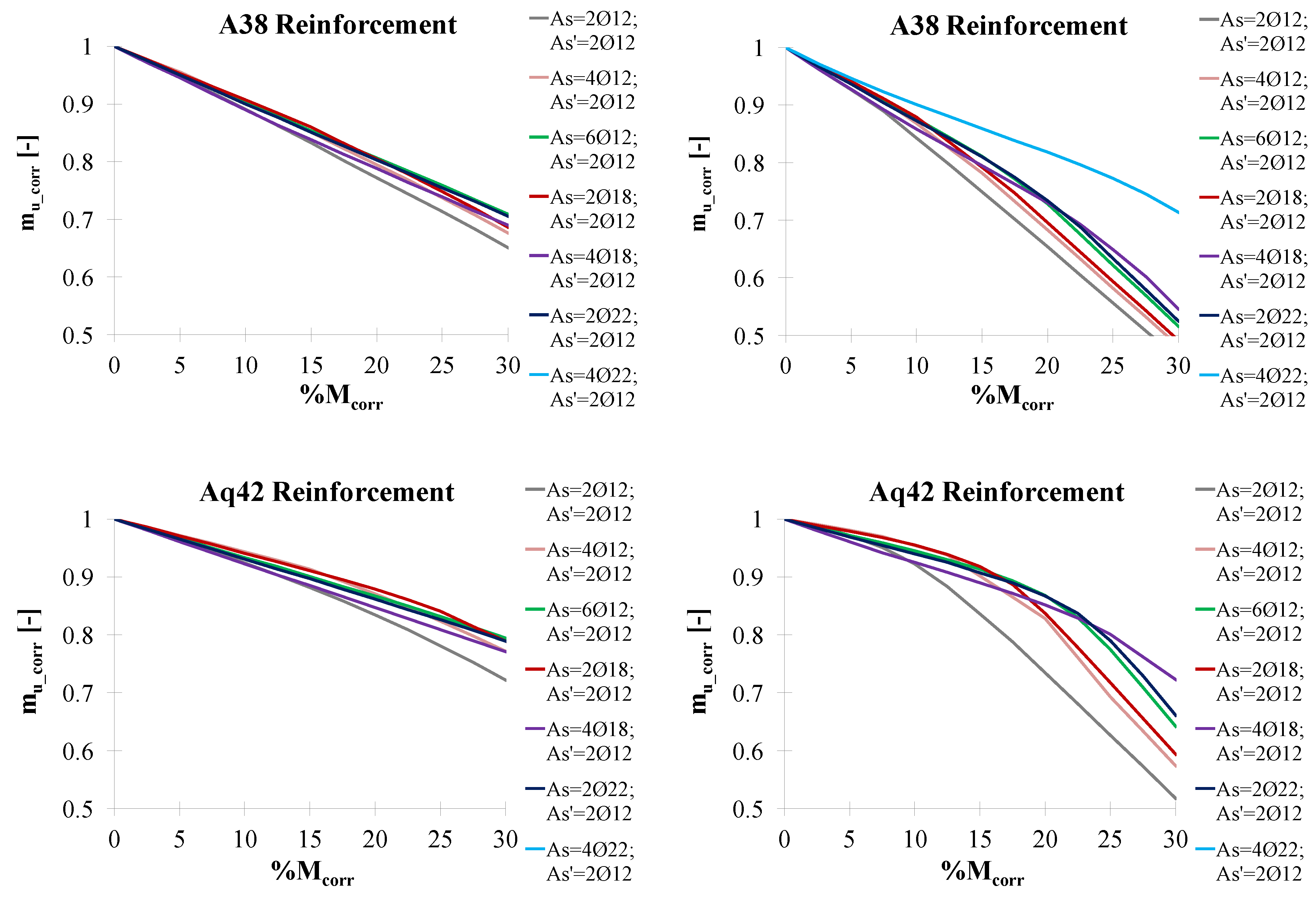
3. Nondimensional Abaci for the Residual Flexural Strength of Corroded Rectangular Sections
4. Conclusions
Author Contributions
Funding
Acknowledgments
Conflicts of Interest
References
- Bossio, A.; Monetta, T.; Bellucci, F.; Lignola, G.P.; Prota, A. Modeling of concrete cracking due to corrosion process of reinforcement bars. Cem. Concr. Res. 2015, 71, 78–92. [Google Scholar] [CrossRef]
- Markeset, G.; Kioumarsi, M. Need for further development in service life modelling of concrete structures in chloride environment. Proc. Eng. 2017, 171, 549–556. [Google Scholar] [CrossRef]
- Almusallam, A.A. Effect of degree of corrosion on the properties of reinforcing steel bars. Constr. Build. Mater. 2001, 15, 361–368. [Google Scholar] [CrossRef]
- Cairns, J.; Plizzari, G.A.; Du, Y.; Law, D.W.; Franzoni, C. Mechanical properties of corrosion-damaged reinforcement. ACI Mater. J. 2005, 102, 256. [Google Scholar]
- Apostolopoulos, C.A.; Papadopoulos, M.P. Tensile and low cycle fatigue behavior of corroded reinforcing steel bars S400. Constr. Build. Mater. 2007, 21, 855–864. [Google Scholar] [CrossRef]
- Lee, H.S.; Cho, Y.S. Evaluation of the mechanical properties of steel reinforcement embedded in concrete specimen as a function of the degree of reinforcement corrosion. Int. J. Fract. 2009, 157, 81–88. [Google Scholar] [CrossRef]
- Apostolopoulos, C.A.; Demis, S.; Papadakis, V.G. Chloride-induced corrosion of steel reinforcement–Mechanical performance and pit depth analysis. Constr. Build. Mater. 2013, 38, 139–146. [Google Scholar] [CrossRef]
- Kashani, M.M.; Crewe, A.J.; Alexander, N.A. Nonlinear stress–strain behaviour of corrosion-damaged reinforcing bars including inelastic buckling. Eng. Struct. 2013, 48, 417–429. [Google Scholar] [CrossRef]
- Kashani, M.M.; Crewe, A.J.; Alexander, N.A. Nonlinear cyclic response of corrosion-damaged reinforcing bars with the effect of buckling. Constr. Build. Mater. 2013, 41, 388–400. [Google Scholar] [CrossRef]
- Caprili, S.; Salvatore, W. Cyclic behaviour of uncorroded and corroded steel reinforcing bars. Constr. Build. Mater. 2015, 76, 168–186. [Google Scholar] [CrossRef]
- Imperatore, S.; Rinaldi, Z.; Drago, C. Degradation relationships for the mechanical properties of corroded steel rebars. Constr. Build. Mater. 2017, 148, 219–230. [Google Scholar] [CrossRef]
- Al-Sulaimani, G.J.; Kaleemullah, M.; Basunbul, I.A. Influence of corrosion and cracking on bond behavior and strength of reinforced concrete members. ACI Struct. J. 1990, 87, 220–231. [Google Scholar]
- Andrade, C.; Alonso, C.; Molina, F.J. Cover cracking as a function of bar corrosion: Part I-Experimental test. Mater. Struct. 1993, 26, 453–464. [Google Scholar] [CrossRef]
- Cabrera, J.G. Deterioration of concrete due to reinforcement steel corrosion. Cem. Concr. Compos. 1996, 18, 47–59. [Google Scholar] [CrossRef]
- Broomfield, J.P. Corrosion of Steel in Concrete: Understanding, Investigation and Repair; CRC Press: London, UK, 2003. [Google Scholar]
- Vidal, T.; Castel, A.; Francois, R. Corrosion process and structural performance of a 17 year old reinforced concrete beam stored in chloride environment. Cem. Concr. Res. 2007, 37, 1551–1561. [Google Scholar] [CrossRef]
- Bossio, A.; Lignola, G.P.; Fabbrocino, F.; Monetta, T.; Prota, A.; Bellucci, F.; Manfredi, G. Nondestructive assessment of corrosion of reinforcing bars through surface concrete cracks. Struct. Concr. 2017, 18, 104–117. [Google Scholar] [CrossRef]
- Almusallam, A.A.; Al-Gahtani, A.S.; Aziz, A.R. Effect of reinforcement corrosion on bond strength. Constr. Build. Mater. 1996, 10, 123–129. [Google Scholar] [CrossRef]
- Lee, H.S.; Noguchi, T.; Tomosawa, F. Evaluation of the bond properties between concrete and reinforcement as a function of the degree of reinforcement corrosion. Cem. Concr. Res. 2002, 32, 1313–1318. [Google Scholar] [CrossRef]
- Coronelli, D. Corrosion cracking and bond strength modeling for corroded bars in reinforced concrete. ACI Struct. J. 2002, 99, 267–276. [Google Scholar]
- Fang, C.; Lundgren, K.; Plos, M.; Gylltoft, K. Bond behaviour of corroded reinforcing steel bars in concrete. Cem. Concr. Res. 2006, 36, 1931–1938. [Google Scholar] [CrossRef]
- Chung, L.; Kim JH, J.; Yi, S.T. Bond strength prediction for reinforced concrete members with highly corroded reinforcing bars. Cem. Concr. Compos. 2008, 30, 603–611. [Google Scholar] [CrossRef]
- Lundgren, K.; Kettil, P.; Hanjari, K.Z.; Schlune, H.; Roman AS, S. Analytical model for the bond-slip behaviour of corroded ribbed reinforcement. Struct. Infrastruct. Eng. 2012, 8, 157–169. [Google Scholar] [CrossRef]
- Choi, Y.S.; Yi, S.T.; Kim, M.Y.; Jung, W.Y.; Yang, E.I. Effect of corrosion method of the reinforcing bar on bond characteristics in reinforced concrete specimens. Constr. Build. Mater. 2014, 54, 180–189. [Google Scholar] [CrossRef]
- Coccia, S.; Imperatore, S.; Rinaldi, Z. Influence of corrosion on the bond strength of steel rebars in concrete. Mater. Struct. 2016, 49, 537–551. [Google Scholar] [CrossRef]
- Rodriguez, J.; Ortega, L.M.; Casal, J. Corrosion of reinforcing bars and service life of reinforced concrete structures: Corrosion and bond deterioration. In Proceedings of the International conference on concrete across borders, Odense, Denmark, 22–25 June 1994; Volume 2, pp. 315–326. [Google Scholar]
- Rodriguez, J.; Ortega, L.M.; Casal, J. Load carrying capacity of concrete structures with corroded reinforcement. In Proceedings of the International Conference on Structural Faults Repairs, London, UK, July 1995; Volume 2, pp. 189–198. [Google Scholar]
- Rodriguez, J.; Ortega, L.M.; Casal, J.; Diez, J.M. Corrosion of reinforcement and service life of concrete structures. In Proceedings of the 7th International Conference on Durability of Building Materials and Components, Stockholm, Sweden, 19–23 May 1996. [Google Scholar]
- Rodriguez, J.; Ortega, L.M.; Casal, J.; Diez, J.M. Assessing structural conditions of concrete structures with corroded reinforcement. In Concrete Repair, Rehabilitation and Protection; Dhir, R.K., Jones, M.R., Eds.; EFN Spon: London, UK, 1996; pp. 65–78. [Google Scholar]
- Rodriguez, J.; Ortega, L.M.; Casal, J. Load carrying capacity of concrete structures with corroded reinforcement. Constr. Build. Mater. 1997, 11, 239–248. [Google Scholar] [CrossRef]
- Capozucca, R.; Cerri, M.; Mariotti, A.; Menditto, G. Behaviour of rc structures subject to reinforcement corrosion. In Proceedings of the 5th International Conference on Structural Faults and Repairs, Edinburgh, UK, 29 June 1993. [Google Scholar]
- Mangat, P.S.; Elgarf, M.S. Flexural strength of concrete beams with corroding reinforcement. ACI Struct. J. 1999, 96, 149–158. [Google Scholar]
- Castel, A.; François, R.; Arliguie, G. Mechanical behaviour of corroded reinforced concrete beams—Part 1: Experimental study of corroded beams. Mater. Struct. 2000, 33, 539–544. [Google Scholar] [CrossRef]
- Torres-Acosta, A.A.; Navarro-Gutierrez, S.; Terán-Guillén, J. Residual flexure capacity of corroded reinforced concrete beams. Eng. Struct. 2007, 29, 1145–1152. [Google Scholar] [CrossRef]
- Azad, A.K.; Ahmad, S.; Azher, S.A. Residual strength of corrosion-damaged reinforced concrete beams. ACI Mater. J. 2007, 104, 40. [Google Scholar]
- Zhang, R.; Castel, A.; François, R. Serviceability limit state criteria based on steel–concrete bond loss for corroded reinforced concrete in chloride environment. Mater. Struct. 2009, 42, 1407. [Google Scholar] [CrossRef]
- Du, Y.; Cullen, M.; Li, C. Structural performance of RC beams under simultaneous loading and reinforcement corrosion. Constr. Build. Mater. 2013, 38, 472–481. [Google Scholar] [CrossRef]
- Xia, J.; Jin, W.L.; Li, L.Y. Effect of chloride-induced reinforcing steel corrosion on the flexural strength of reinforced concrete beams. Magaz. Concr. Res. 2012, 64, 471–485. [Google Scholar] [CrossRef]
- Zhu, W.; François, R.; Coronelli, D.; Cleland, D. Effect of corrosion of reinforcement on the mechanical behaviour of highly corroded RC beams. Eng. Struct. 2013, 56, 544–554. [Google Scholar] [CrossRef]
- Zhu, W.; François, R. Corrosion of the reinforcement and its influence on the residual structural performance of a 26-year-old corroded RC beam. Constr. Build. Mater. 2014, 51, 461–472. [Google Scholar] [CrossRef]
- Vu KA, T.; Stewart, M.G. Structural reliability of concrete bridges including improved chloride-induced corrosion models. Struct. Saf. 2000, 22, 313–333. [Google Scholar]
- Coronelli, D.; Gambarova, P. Structural assessment of corroded reinforced concrete beams: Modeling guidelines. J. Struct. Eng. 2004, 130, 1214–1224. [Google Scholar] [CrossRef]
- El Maaddawy, T.; Soudki, K.; Topper, T. Analytical model to predict nonlinear flexural behavior of corroded reinforced concrete beams. ACI Struct. J. 2005, 102, 550. [Google Scholar]
- Val, D.V. Deterioration of strength of RC beams due to corrosion and its influence on beam reliability. J. Struct. Eng. 2007, 133, 1297–1306. [Google Scholar] [CrossRef]
- Kioumarsi, M.M.; Hendriks, M.A.; Kohler, J.; Geiker, M.R. The effect of interference of corrosion pits on the failure probability of a reinforced concrete beam. Eng. Struct. 2016, 114, 113–121. [Google Scholar] [CrossRef]
- Imperatore, S.; Leonardi, A.; Rinaldi, Z. Mechanical behaviour of corroded rebars in reinforced concrete elements. In Mechanics, Models and Methods in Civil Engineering; Maceri, F., Ed.; Springer: Berlin/Heidelberg, Germany, 2012; pp. 207–220. [Google Scholar]
- Imperatore, S.; Leonardi, A.; Rinaldi, Z. Strength decay of RC sections for chloride attack. Int. J. Struct. Integr. 2016, 7, 194–212. [Google Scholar] [CrossRef]
- Kioumarsi, M.; Markeset, G.; Hooshmandi, S. Effect of pit distance on failure probability of a corroded RC beam. Proc. Eng. 2017, 171, 526–533. [Google Scholar] [CrossRef]
- Imperatore, S.; Zucconi, M.; Ferracuti, B. Pitting corrosion effects on the seismic behaviour of existing RC buildings. In Proceedings of the XVII Convegno ANIDIS L’ingegneria Sismica in Italia 2017; Pisa University Press: Pisa, Italy, 2017; pp. 114–124. [Google Scholar]
- Bossio, A.; Fabbrocino, F.; Monetta, T.; Lignola, G.P.; Prota, A.; Manfredi, G.; Bellucci, F. Corrosion effects on seismic capacity of reinforced concrete structures. Corros. Rev. 2019, 37, 45–56. [Google Scholar] [CrossRef]
- Apostolopoulos, C.; Drakakaki, A.; Basdeki, M. Seismic assessment of RC column under seismic loads. Int. J. Struct. Integr. 2019, 10, 41–54. [Google Scholar] [CrossRef]
- Zucconi, M.; Ferlito, R.; Sorrentino, L. Validation and extension of a statistical usability model for unreinforced masonry buildings with different ground motion intensity measures. Bull. Earthq. Eng. 2019, 1–29. [Google Scholar] [CrossRef]
- Romano, F.; Faggella, M.; Gigliotti, R.; Zucconi, M.; Ferracuti, B. Comparative seismic loss analysis of an existing non-ductile RC building based on element fragility functions proposals. Eng. Struct. 2018, 177, 707–723. [Google Scholar] [CrossRef]
- Ferlito, R.; Guarascio, M.; Zucconi, M. Assessment of a vulnerability model against post-earthquake damage data: The case study of the historic city centre of L’Aquila in Italy. In Proceedings of the 9th International Conference on Earthquake Resistant Engineering Structures, A Coruña, Spain, 8–10 July 2013. [Google Scholar]
- Di Carlo, F.; Meda, A.; Rinaldi, Z. Numerical evaluation of the corrosion influence on the cyclic behaviour of RC columns. Eng. Struct. 2017, 153, 264–278. [Google Scholar] [CrossRef]
- DIANA, User’s Manual, Release 9.4; TNO DIANA BV: Delft, The Netherlands, 2010.
- Capozucca, R.; Cerri, M.N. Influence of reinforcement corrosion—In the compressive zone—On the behaviour of RC beams. Eng. Struct. 2003, 25, 1575–1583. [Google Scholar] [CrossRef]
- Zandi Hanjari, K.; Kettil, P.; Lundgren, K. Analysis of mechanical behavior of corroded reinforced concrete structures. ACI Struct. J. 2011, 108, 532–541. [Google Scholar]
- Kioumarsi, M.M.; Hendriks, M.A.; Geiker, M.R. Quantification of the interference of localised corrosion on adjacent reinforcement bars in a concrete beam in bending. Nord. Concr. Res. 2014, 49, 39–57. [Google Scholar]
- Kioumarsi, M.M.; Hendriks, M.A.; Geiker, M.R. Interference of localised corrosion in adjacent reinforcement bar of a beam in bending. In Proceedings of the CIC—Concrete innovation conference, Oslo, Norway, 11–14 June 2014. [Google Scholar]
- Fib. Fib Model Code for Concrete Structures 2010; Ernst & Sohn. Wiley: Berlin, Germany, 2013. [Google Scholar]
- European Committee for Standardization. Eurocode 2: Design of Concrete Structures—Part 1–1: General Rules and Rules for Buildings; British Standards Institution: Brussels, Belgium, 2004. [Google Scholar]
- Mander, J.B.; Priestley, M.J.; Park, R. Theoretical stress-strain model for confined concrete. J. Struct. Eng. 1988, 114, 1804–1826. [Google Scholar] [CrossRef]


| Tension Reinforcements | Compression Reinforcements | ||
|---|---|---|---|
| 2ϕ14 | 2ϕ14 | ||
| 3ϕ16 | 3ϕ16 | ||
| 3ϕ20 | 3ϕ16 | 3ϕ20 | |
| 3ϕ24 | 2ϕ14 | 3ϕ16 | 3ϕ20 |
| Tension Reinforcements | Compression Reinforcements | ||
|---|---|---|---|
| 6ϕ14 | 4ϕ14 | ||
| 6ϕ16 | 4ϕ16 | ||
| 6ϕ20 | 4ϕ20 | ||
| 6ϕ24 | 4ϕ24 | ||
| 8ϕ24 | 4ϕ24 | 6ϕ24 | 8ϕ24 |
© 2019 by the authors. Licensee MDPI, Basel, Switzerland. This article is an open access article distributed under the terms and conditions of the Creative Commons Attribution (CC BY) license (http://creativecommons.org/licenses/by/4.0/).
Share and Cite
Bossio, A.; Imperatore, S.; Kioumarsi, M. Ultimate Flexural Capacity of Reinforced Concrete Elements Damaged by Corrosion. Buildings 2019, 9, 160. https://doi.org/10.3390/buildings9070160
Bossio A, Imperatore S, Kioumarsi M. Ultimate Flexural Capacity of Reinforced Concrete Elements Damaged by Corrosion. Buildings. 2019; 9(7):160. https://doi.org/10.3390/buildings9070160
Chicago/Turabian StyleBossio, Antonio, Stefania Imperatore, and Mahdi Kioumarsi. 2019. "Ultimate Flexural Capacity of Reinforced Concrete Elements Damaged by Corrosion" Buildings 9, no. 7: 160. https://doi.org/10.3390/buildings9070160
APA StyleBossio, A., Imperatore, S., & Kioumarsi, M. (2019). Ultimate Flexural Capacity of Reinforced Concrete Elements Damaged by Corrosion. Buildings, 9(7), 160. https://doi.org/10.3390/buildings9070160