Integrated Parametric Shaping of Curvilinear Steel Bar Structures of Canopy Roofs


Abstract
1. Introduction
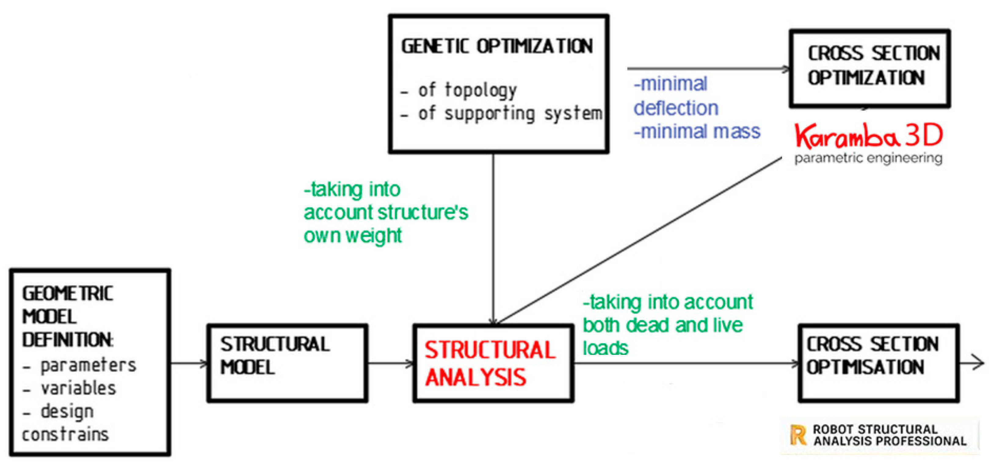
2. Materials and Methods
3. Results
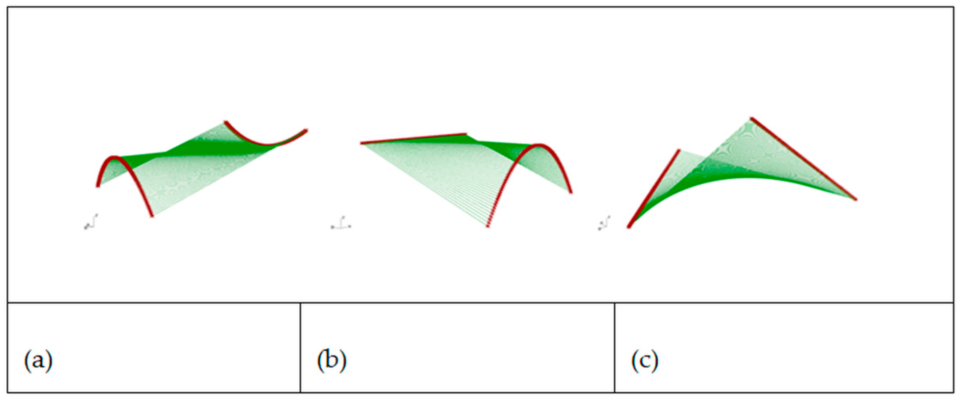
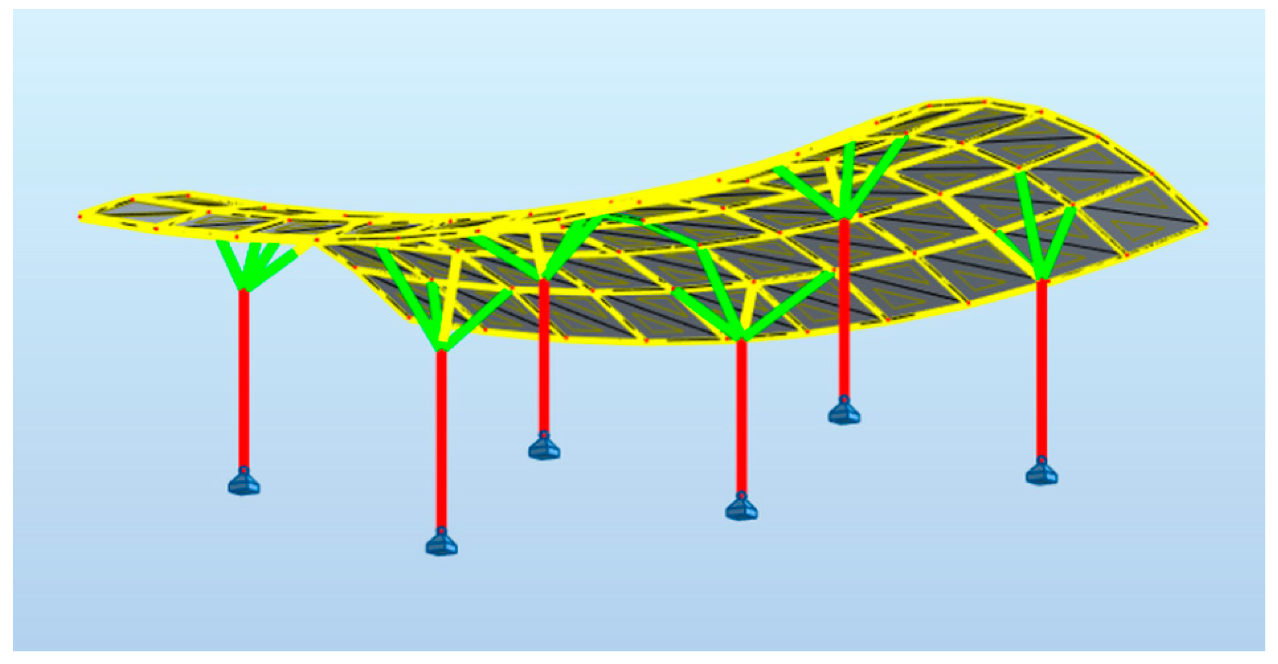
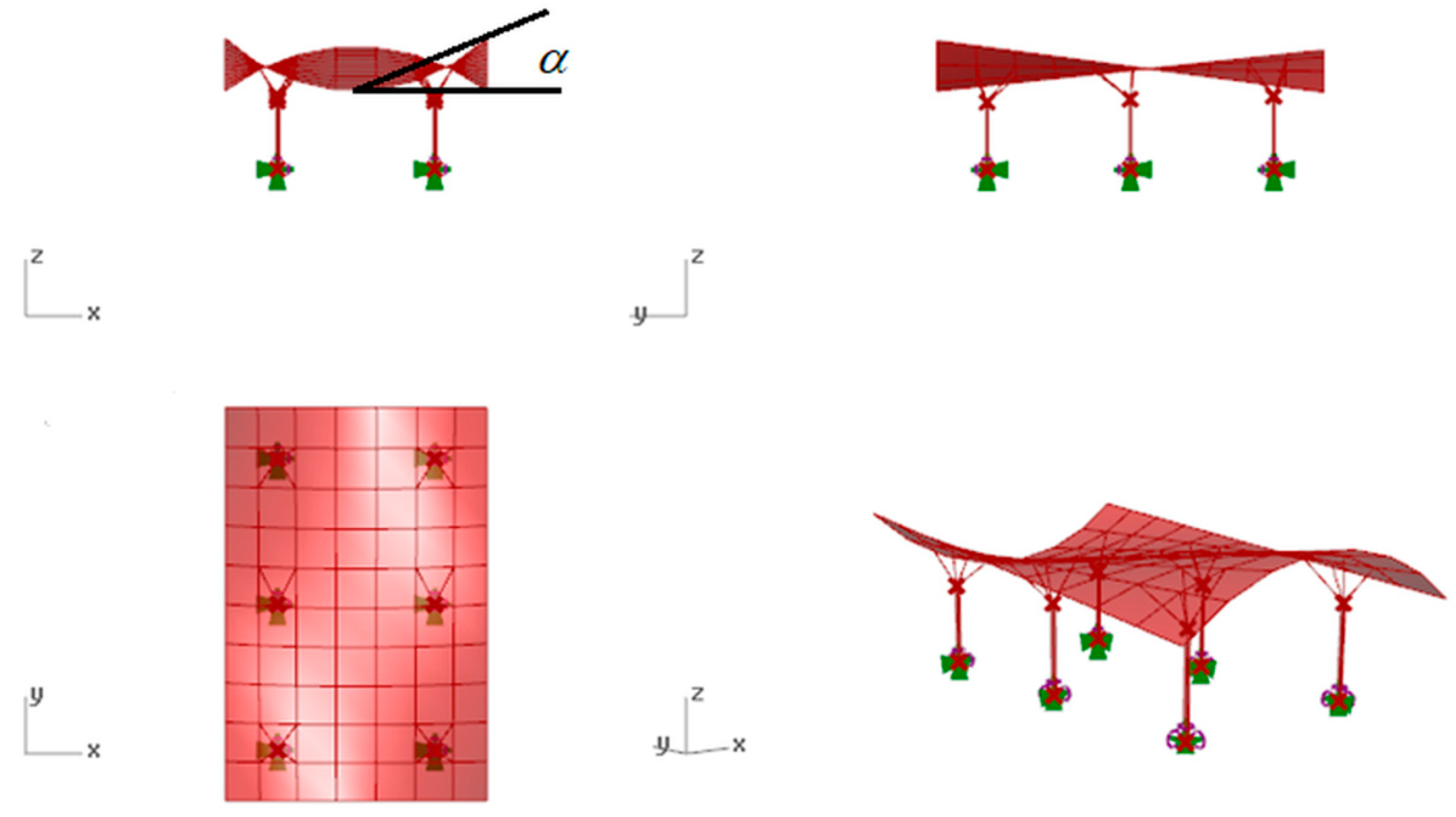
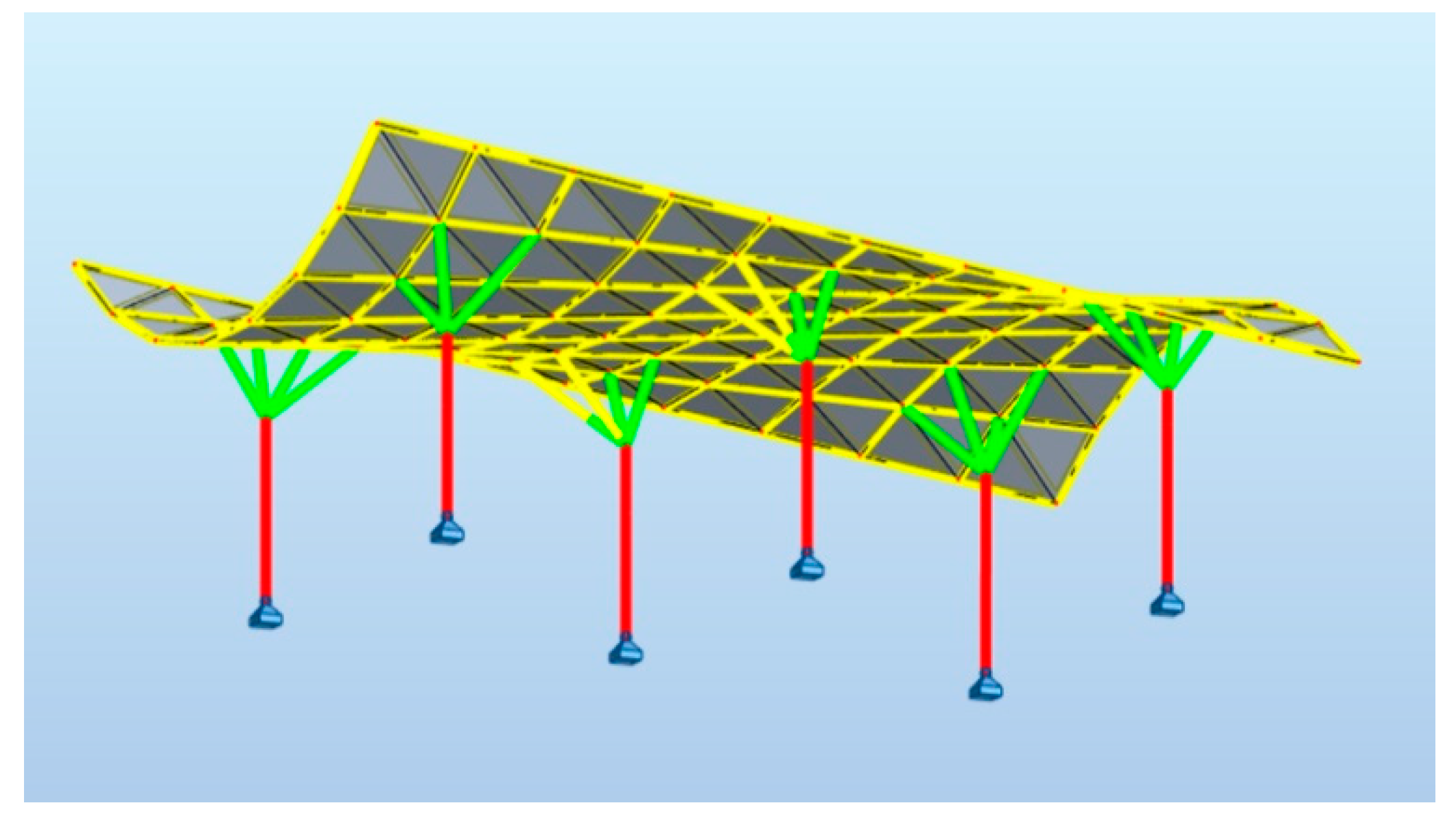
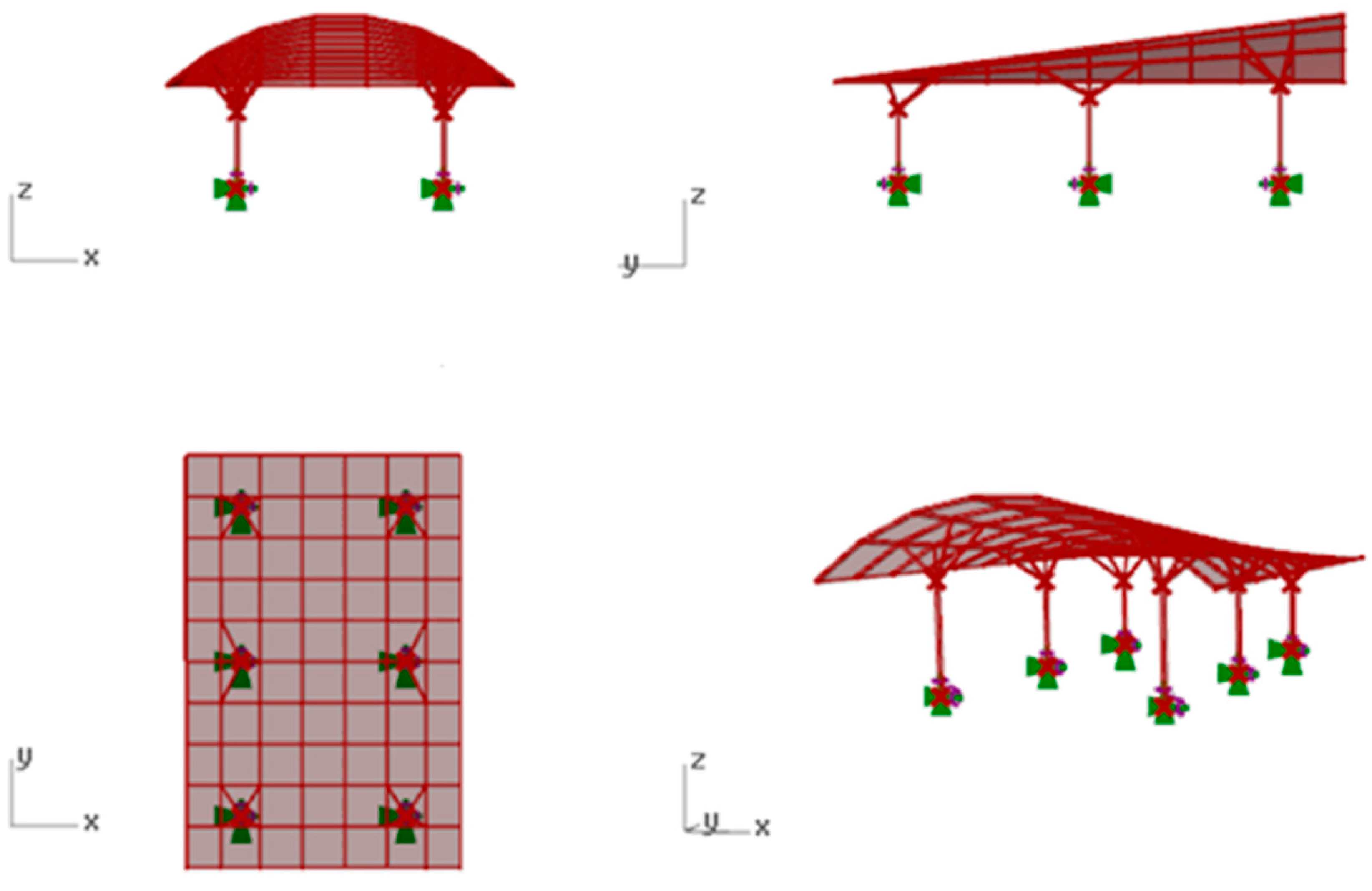
3.1. Geometric Shaping of the Base Surfaces
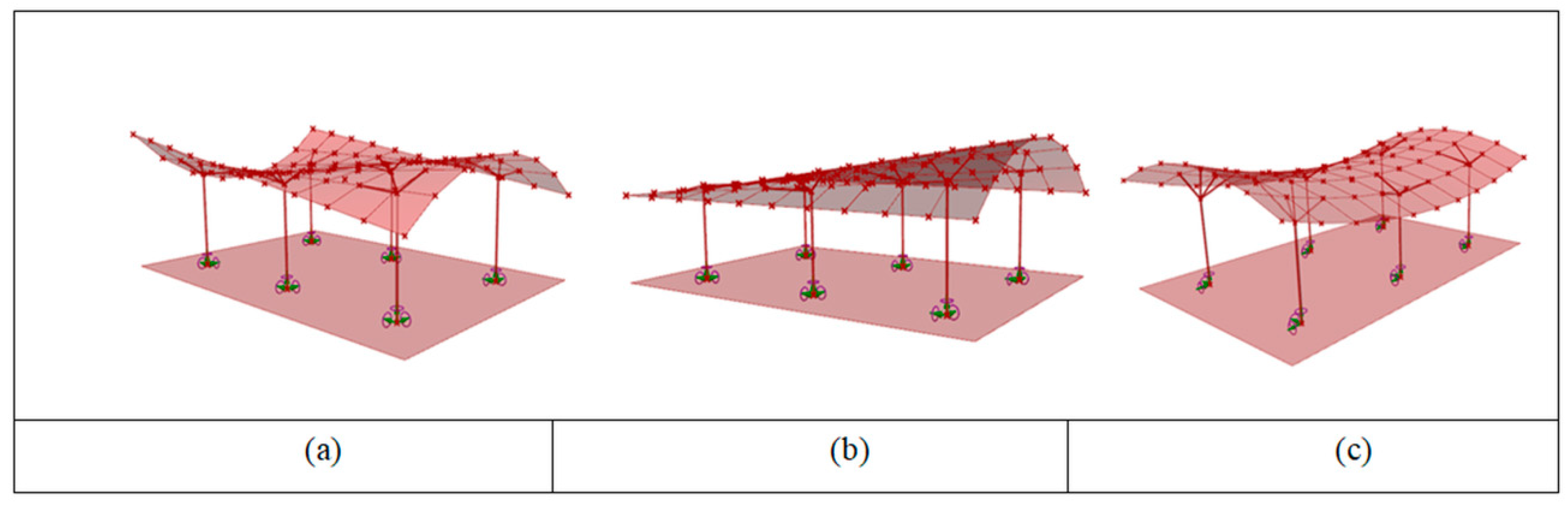
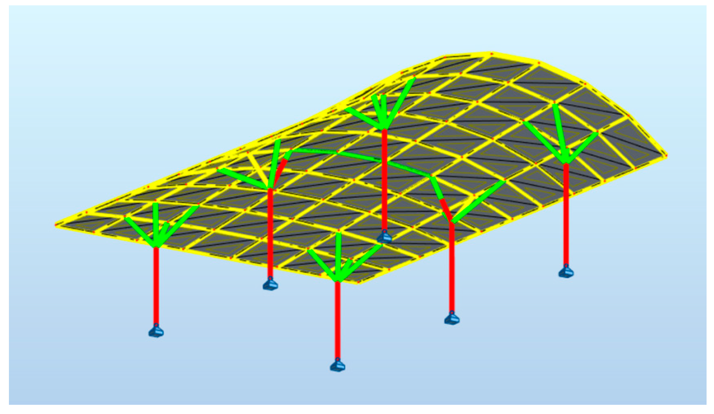
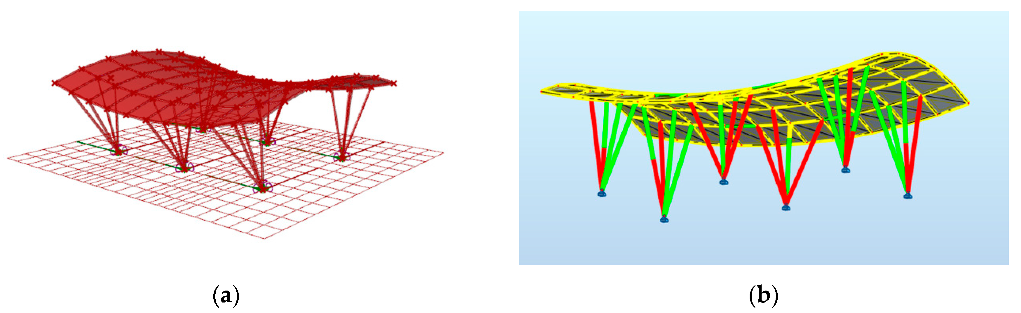
3.2. Results of Evolutionary Optimization Performed by Galapagos
- -
- Due to Ultimate Limit States (ULS) the it should be respectively:
- -
- Ed/Rd ≤ 1 at each cross section, where: Ed–is a design
- -
- value of the effects of actions, Rd represents the design value of the corresponding resistance, however this verification is fulfilled automatically
- -
- Due to Serviceability Limit States (SLS) deflection limit for any load case should fulfill the condition f = L/250, where L it is a span of the structure, so for the considered structures f ≤ 40 mm
- -
- Kind of the structural material applied: steel S235.
- -
- Dimensions of the rectangular plan: 15 m × 10 m
- -
- Number of supports: 6
- -
- Height of the whole structure: 5 m
- -
- Height of the roof’s surface: 2 m
- -
- Self-weight as the sum of the lattice’s weight and columns’ weight as well as cladding weight calculated by Karamba 3D for each structure individually
- -
- Kind of cladding: steel with weight of 0.07 kN/m2 (thickness of the steel sheet equal to 5 mm)
- -
- Elements’ cross sections: circular hollow, walls’ thickness not less than 3.2 mm
- -
- Location of the supports: within the rectangular plan, however no farer than 2 meters from the place’s border
- -
- Minimal bars’ length: 1.0 m–1.5 m
- -
- Maximum bars’ length: 1.5 m–2.0 m
- -
- Location of the column branching node in the scope of 70% d–90% d, where d is the distance of the column’s base to the roof’s surface
- -
- Cross section diameter: 4.83 cm–6.0 cm for lattice and column branches
- -
- 4.83 cm–7.0 cm for columns
3.3. Results of the Structural Optimization Performed by Autodesk Robot Structural Analysis Software
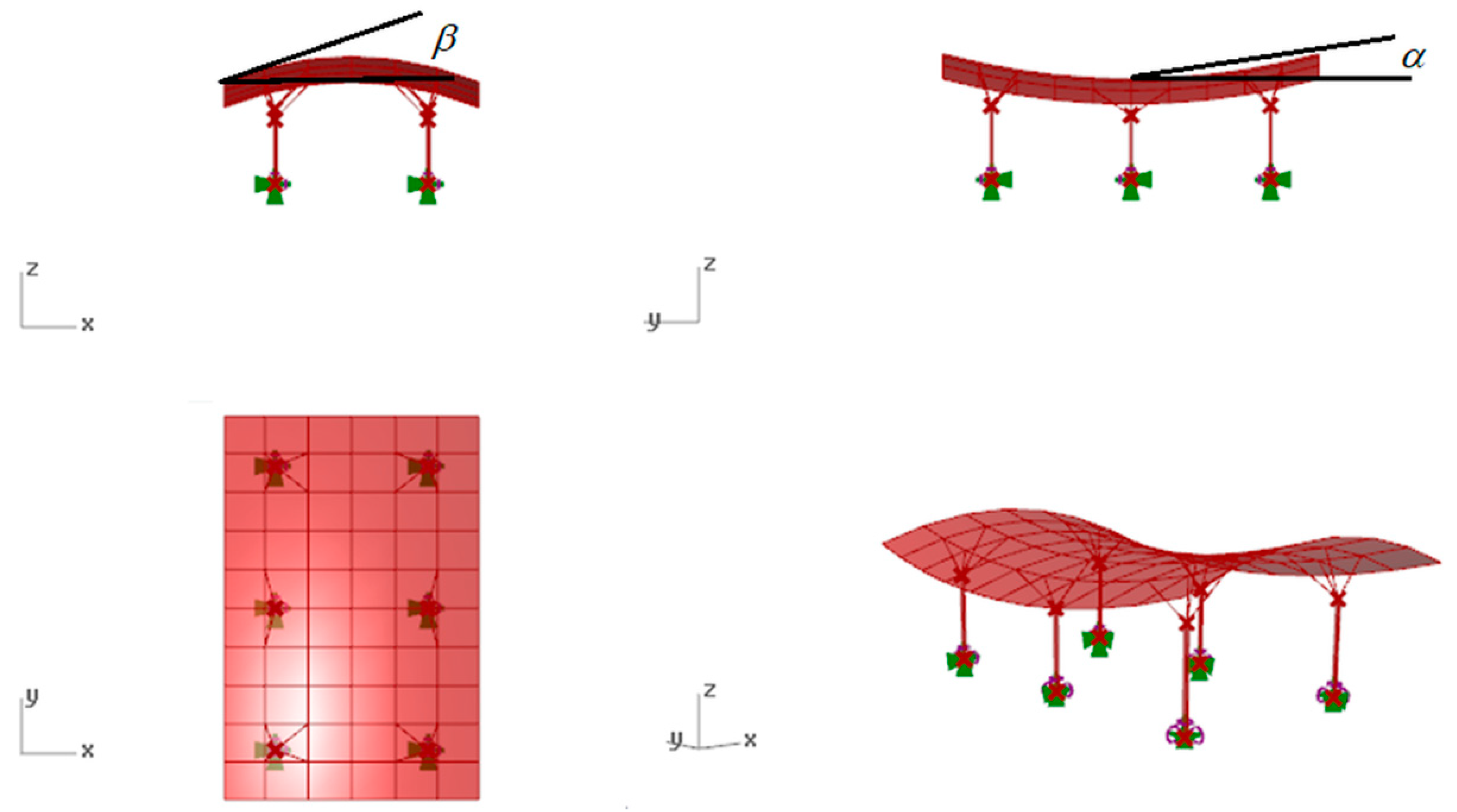
3.3.1. Hyperbolic Paraboloid Canopy Roof
- μ1 = 0.8 in the case of even load, (the case of evenly spreading snow on the roof)
3.3.2. Cylindroid Canopy Roof
- Even snow load, (the case of evenly spreading snow on the roof);
- Uneven snow load, (the case of uneven distribution of snow on the roof resulting from the shape of the roof and the guidelines contained in [36]);
- Drifted snow load, (taking into account exceptional situations, when snow can be particularly cumulated in the recessed part of the roof according to [36].
- μ1 = 0.8 in the case of even load,
- μ3 = 2 in the case of uneven snow load
- μ2 = 1.33 in the case of drifted snow load
3.3.3. Conoid Canopy Roof
- Even snow load, (the case of evenly spreading snow on the roof)
- Uneven snow load, (the case of uneven distribution of snow on the roof resulting from the shape of the roof and the guidelines contained in [36]).
- μ1 = 0.8 in the case of even load,
- μ3 = 2 in the case of uneven snow load.
4. Discussion
5. Conclusions
Funding
Conflicts of Interest
References
- Oxman, R. Theory and design in the first digital age. Des. Stud. 2006, 27, 229–265. [Google Scholar] [CrossRef]
- Hewitt, M. Representational Forms and Modes of Conception; an Approach to the History of Architectural Drawing. J. Arch. Educ. 2014, 39, 2–9. [Google Scholar]
- Unwin, S. Analyzing architecture through drawing. Build. Res. Inf. 2007, 35, 101–110. [Google Scholar] [CrossRef]
- Dzwierzynska, J. Direct construction of Inverse Panorama from a Moving View Point. Procedia Eng. 2016, 161, 1608–1614. [Google Scholar] [CrossRef]
- Dzwierzynska, J. Computer-Aided Panoramic Images Enriched by Shadow Construction on a Prism and Pyramid Polyhedral Surface. Symmetry 2017, 9, 214. [Google Scholar] [CrossRef]
- Dzwierzynska, J. Single-image-based Modelling Architecture from a Historical Photograph. IOP Conf. Ser. Mater. Sci. Eng. 2017, 245, 062015. [Google Scholar] [CrossRef]
- Dzwierzynska, J. Reconstructing Architectural Environment from a Panoramic Image. IOP Conf. Ser. Earth Environ. Sci. 2016, 44, 042028. [Google Scholar] [CrossRef]
- Biagini, C.; Donato, V. Behind the complexity of a folded paper. In Proceedings of the Conference on Modelling from Digital to Physical, Milano, Italy, 11–12 November 2013; pp. 160–169. [Google Scholar]
- Luo, Y.; Dias, J.M. Development of a Cooperative Integration System for AEC Design. In Cooperative Design, Visualization, and Engineering (CDVE 2004); Luo, Y., Ed.; Lecture Notes in Computer Science; Springer: Berlin/Heidelberg, Germany, 2004; Volume 3190. [Google Scholar] [CrossRef]
- Wang, J.; Chong, H.-Y.; Shou, W.; Wang, X.; Guo, J. BIM-Enabled design Collaboration for Complex in Cooperative Design, Visualization, and Engineering Building. In Proceedings of the 9-th International Conference (CDVE 2013), Alcudia, Mallorca, Spain, 22–25 September 2013; Luo, Y., Ed.; Springer: Heindelberg, Germany; New York, NY, USA; Dordrecht, The Netherlands; London, UK, 2013; ISBN 978-3-642-40840-3. [Google Scholar]
- Kolarevic, B. Architecture in the Digital Age: Design and Manufacturing, 1st ed.; Spon Press: London, UK, 2003; pp. 20–98. ISBN 0-415-27820-1. [Google Scholar]
- Barlish, K.; Sullivan, K. How to measure the benefits of BIM—A case study approach. Autom. Constr. 2012, 24, 149–159. [Google Scholar] [CrossRef]
- Elango, M.; Devadas, M.D. Multi-Criteria Analysis of the Design Decisions in architectural Design Process during the Pre-Design Stage. Int. J. Eng. Technol. 2014, 6, 1033–1046. [Google Scholar]
- Turrin, M.; von Buelow, P.; Stouffs, R. Design explorations of performance driven geometry in architectural design using parametric modeling and genetic algorithms. Adv. Eng. Inform. 2011, 25, 656–675. [Google Scholar] [CrossRef]
- Wortmann, T.; Tuncer, B. Differentiating parametric design: Digital Workflows in Contemporary Architecture and Construction. Des. Stud. 2017, 52, 173–197. [Google Scholar] [CrossRef]
- Hardling, J.E. Meta-parametric Design. Des. Stud. 2017, 52, 73–95. [Google Scholar] [CrossRef]
- Oxman, R. Thinking difference: Theories and models of parametric design thinking. Des. Stud. 2017, 52, 4–39. [Google Scholar] [CrossRef]
- Bhooshan, S. Parametric design thinking: A case study of practice-embedded architectural research. Des. Stud. 2017, 52, 115–143. [Google Scholar] [CrossRef]
- Kuś, S. General principles of shaping the structure. In General Building Construction, Building Elements and Design Basics; Arkady: Warsaw, Poland, 2011; Volume 3, pp. 12–71. (In Polish) [Google Scholar]
- Foraboschi, P. The central role played by structural design in enabling the construction of buildings that advanced and revolutionized architecture. Constr. Build. Mater. 2016, 114, 956–997. [Google Scholar] [CrossRef]
- Woliński, S. On the criteria of shaping structures. Sci. Pap. Rzesz. Univ. Technol. 2011, 276, 399–408. [Google Scholar]
- Januszkiewicz, K.; Banachowicz, M. Nonlinear Shaping Architecture Designed with Using Evolutionary Structural Optimization Tools. IOP Conf. Ser. Mater. Sci. Eng. 2017, 245. [Google Scholar] [CrossRef]
- Dzwierzynska, J. Rationalized Algorithmic-Aided Shaping a Responsive Curvilinear Steel Bar Structure. Buildings 2019, 9, 61. [Google Scholar] [CrossRef]
- Foraboschi, P. Optimal design of glass plates loaded transversally. Mater. Des. 2014, 62, 443–458. [Google Scholar] [CrossRef]
- Minseok, K. A Study on Efficient Approaches for Grasshopper Programming in Architectural Design Process. Korean J. Comput. Des. Eng. 2016, 21, 453–461. [Google Scholar]
- Available online: https://www.rhino3d.com/ (accessed on 19 March 2019).
- Preisinger, C. Linking Structure and Parametric Geometry. Arch. Des. 2013, 83, 110–113. [Google Scholar] [CrossRef]
- Autodesk. Available online: https://www.autodesk.com/ (accessed on 25 February 2019).
- Pottman, H.; Asperl, A.; Hofer, M.; Kilian, A. Architectural Geometry, 1st ed.; Bentley Institute Press: Exton, PA, USA, 2007; pp. 35–194. ISBN 978-1-934493-04-5. [Google Scholar]
- Dzwierzynska, J.; Prokopska, A. Pre-Rationalized Parametric Designing of Roof Shells Formed by Repetitive Modules of Catalan Surfaces. Symmetry 2018, 10, 105. [Google Scholar] [CrossRef]
- Dzwierzynska, J. Shaping curved steel rod structures. Tech. Trans. Civ. Eng. 2018, 8, 87–98. [Google Scholar] [CrossRef]
- Wang, D. Optimization of support positions to minimize the maximal deflection of structure. Int. J. Solids Struct. 2004, 41, 7445–7458. [Google Scholar] [CrossRef]
- PN-EN 1990: 2004. Eurocode. Basis of Structural Design; PKN: Warsaw, Poland, 2004. (In Polish) [Google Scholar]
- PN-EN 1993-1-1:2006. Eurocode 3. Design of Steel Structures. Part 1-1: General Rules and Rules for Buildings; PKN: Warsaw, Poland, 2006. (In Polish) [Google Scholar]
- PN-EN 1991-1-1:2004. Eurocode 1. Actions on Structures. Part 1-1: General Actions-Densities, Self-Weight, Imposed Loads for Buildings; PKN: Warsaw, Poland, 2004. (In Polish) [Google Scholar]
- PN-EN 1991-1-1:2004. Eurocode 1. Actions on Structures. Part 1-3: General Actions-Snow Loads; PKN: Warsaw, Poland, 2004. (In Polish) [Google Scholar]
- Tajs-Zielińska, K.; Bochenek, B. Topology Optimization-Engineering Contribution to Architectural Design. IOP Conf. Ser. Mater. Sci. Eng. 2017, 245. [Google Scholar] [CrossRef]
- Foraboschi, P. Effectiveness of novel methods to increase the FRP-masonry bond capacity. Compos. Part B Eng. 2016, 107, 214–232. [Google Scholar] [CrossRef]


| Bars’ (Lattice and Branches) Cross Sections Radius/Wall Thickness [mm] | Column Cross Section Radius/Wall Thickness [mm] | Column’s Length [m] | Maximum Displacement [mm] | Ratio [%] | Column Position in Coordinates x, y | Mass [kg] |
|---|---|---|---|---|---|---|
| Structure 1–hyperbolic paraboloid canopy roof with grid divisson: 6 × 10 | ||||||
| 4.83/0.32 | 7.00/0.32 | L = 70%d | 21 | 30 | x1 = 2.0, y1 = 1.85 x2 = 8.0, y2 = 1.85 x3 = 2.0, y3 = 7.5 x4 = 8.0, y4 = 7.5 x5 = 2.0, y5 = 13.15 x6 = 8.0, y6 = 13.15 | 1016.95 |
| Structure 2–cylindroid canopy roof with grid division: 7 × 10 | ||||||
| 4.83/0.32 | 7.00/0.32 | l= 70%d | 28 | 34 | x1 = 2.0, y1 = 2.0 x2 = 8.0, y2 = 2.0 x3 = 2.0, y3 = 7.5 x4 = 8.0, y4 = 7.5 x5 = 2.0, y5 = 13.0 x6 = 10.0, y6 = 13.0 | 1058.73 |
| Structure 3–conoid canopy roof with grid division: 7 × 10 | ||||||
| 4.83/0.32 | 7.00/0.32 | L = 70%d | 28 | 35 | x1 = 2.0, y1 = 1.94 x2 = 8.0, y2 = 1.94 x3 = 2.0, y3 = 7.5 x4 = 8.0, y4 = 7.5 x5 = 2.0, y5 = 13.06 x6 = 8.0, y6 = 13.06 | 1047.61 |
| Kind of Member | Cross Section Radius/Wall Thickness [mm] | Ratio [%] |
|---|---|---|
| Lattice’s bars | 101.6/3.6 | 92 |
| Branches | 106.6/3.2 | 94 |
| Columns | 139.0/4.5 | 94 |
| Kind of Member | Cross Section Radius/Wall Thickness [mm] | Ratio [%] |
|---|---|---|
| Lattice’s bars | 114.3/3.2 | 93 |
| Branches | 101.6/3.6 | 85 |
| Columns | 159.0/4.5 | 95 |
| Kind of Member | Cross Section Radius/Wall Thickness [mm] | Ratio [%] |
|---|---|---|
| Lattice’s bars | 101.6/3.6 | 90 |
| Branches | 114.4/4.0 | 79 |
| Columns | 139.7/4.0 | 46 |
| Kind of Member | Cross Section Radius/Wall Thickness [mm] | Ratio [%] |
|---|---|---|
| Lattice’s bars | 101/3.2 | 88 |
| Branches | 76.1/3.6 | 85 |
© 2019 by the author. Licensee MDPI, Basel, Switzerland. This article is an open access article distributed under the terms and conditions of the Creative Commons Attribution (CC BY) license (http://creativecommons.org/licenses/by/4.0/).
Share and Cite
Dzwierzynska, J. Integrated Parametric Shaping of Curvilinear Steel Bar Structures of Canopy Roofs. Buildings 2019, 9, 72. https://doi.org/10.3390/buildings9030072
Dzwierzynska J. Integrated Parametric Shaping of Curvilinear Steel Bar Structures of Canopy Roofs. Buildings. 2019; 9(3):72. https://doi.org/10.3390/buildings9030072
Chicago/Turabian StyleDzwierzynska, Jolanta. 2019. "Integrated Parametric Shaping of Curvilinear Steel Bar Structures of Canopy Roofs" Buildings 9, no. 3: 72. https://doi.org/10.3390/buildings9030072
APA StyleDzwierzynska, J. (2019). Integrated Parametric Shaping of Curvilinear Steel Bar Structures of Canopy Roofs. Buildings, 9(3), 72. https://doi.org/10.3390/buildings9030072