Abstract
The dynamic development of the automotive industry and improvements in quality of life have caused a significant increase in the production of car tires. Unfortunately, when the useful life of these products comes to an end, the problem of their disposal arises. The article presents the results of tests of epoxy mortars in which granules made from waste tires were used as a substitute for sand in the amount of 0, 20, 40, 60, 80 and 100% vol. respectively. The available literature lacks information about resin composites that arise with such a large or complete replacement of sand with rubber waste. Along with the increase in the content of waste, the values of strength parameters of composites decreased; however, a material characterized by very low water absorption, that is lightweight and with a low thermal conduction coefficient was obtained. Using the ADINA program, numerical simulations were carried out regarding the temperature distribution in a part of the building structure containing modified rubber mortar. The results of the simulation confirmed the possibility of practical use of the obtained composite due to its good thermal insulation properties. This approach to testing composites modified with rubber waste is innovative.
1. Introduction
In recent years, considerable attention has been paid to the concept of sustainable development, which raises issues related to caring for the environment [1,2,3]. This forces the need for rational waste management in the interests of future generations. Meeting the assumptions of sustainable development requires a search for sensible ways of disposing of wastes, especially those that are extremely difficult to dispose of, for example, plastics, glass and rubber. Car tires are particularly difficult to dispose of. This waste is constantly being produced and will continue to be, due to the dynamic development of the automotive industry. Improvements in quality of life cause a rapid increase in the purchasing of cars, which is why excess tire waste has become a global problem. Waste rubber from tires is not biodegradable, and the crosslinked structure and various additives used in the production process make the natural decay very long, in the order of hundreds of years. The methods used to dispose of tire waste, such as incineration or storage, cause the formation of harmful gases, as well as serious pollution of soil, water and atmosphere. This is why alternative recycling methods are sought [4,5]. To limit the growth of automotive-grade waste rubber, research is being conducted on its re-use. This process can be implemented on many levels, i.e., through:
- re-use of tires in the automotive industry after their re-treading,
- energy recycling—using tires as a source of energy,
- the use of entire tires for reinforcing road embankments and reinforcing ground, construction of retaining walls or road culverts,
- material recycling—shredded tires can be used as an admixture for other materials, thus improving their properties (e.g., adhesion, plasticity, thermal resistance, etc.)
The latter seems to be particularly interesting, as it creates the possibility of obtaining materials with unique properties, and is also in line with the principles of sustainable development [6,7]. After being broken up, waste rubber can be successfully used in industry, in the construction sector. Broken-up waste can take different forms [8,9] and size, which translates into different application possibilities.
Composites containing waste rubber are characterized by lower mass, the ability to absorb energy and the insulation of heat and sound [10,11,12,13,14]. Waste rubber granules can also be a valuable substitute for aggregates in concrete-like building composites. The degree of accessibility, transport costs and the quality of natural aggregates, may in many cases be worse in comparison to fillers obtained from waste materials, e.g., rubber. Many research centers around the world have for years been conducting research on the possibility of using recycled aggregates, including waste rubber granulate. There are also more and more companies dealing in the processing of waste tires into granules which can act as aggregates.
Numerous studies concern the use of waste rubber in cement concrete [7,10,11,12,15,16,17,18,19]. The addition of waste rubber usually significantly reduced the strength parameters of these composites [11,17,20,21,22]. However, with a substitution not exceeding 20%, a significant reduction in strength can be avoided. The use of appropriate coupling agents is also helpful in this regard [16]. Rubberized concrete shows high resistance to cyclic freeze-thawing, acid attack and chloride ion penetration [16]. The authors of publications [17,18] also examined the behavior of mortars containing waste rubber at elevated temperatures, in the order of 150–400 °C. This approach is important due to the possibility of the release of harmful substances during a fire. It was found that at 3–10% waste rubber content there is no risk of the modifier burning. In addition to publications devoted to the use of rubber granules in cementitious concrete, articles on the study of resin composites modified with waste rubber can also be found [11,23,24,25]. Jafari and Toufigh [25] conducted a comprehensive study of epoxy concretes containing crumb and chipped rubber replacing fine and coarse aggregates in an amount from 0 to 30%. M. Barbuta et al. [23] confirmed that the addition of waste rubber in polymer concrete causes a decrease in strength parameters. The concrete obtained by such a modification is, however, considerably lighter and can successfully provide an alternative to cement concrete in applications such as prefabricated elements for acoustic protection, thermal insulation, industrial floors, and pavements.
Concrete and resin mortars are cementless composites, which include synthetic resins, their hardeners and aggregate [26,27,28,29]. Epoxy mortars are included in this group of materials. They have good insulating properties and very low water absorption, while retaining the advantageous properties of resin mortar, including high mechanical strength and excellent chemical resistance [30,31,32,33,34,35]. The article describes the results of research on modified epoxy mortars. The modification consisted in the substitution of aggregates with waste rubber granulate in an amount from 0 to 100% by volume, which is a novelty in the field of composites containing this type of waste and may be a valuable contribution to the comprehensive evaluation of mortar properties containing alternative aggregate. A composite was obtained with a significantly reduced bulk density and a low thermal conduction coefficient as well as very low water absorption while maintaining satisfactory strength parameters.
To demonstrate the suitability of the designed composite for its application in structural solutions of building partitions, computer simulations were used. The proposed solution for the balcony slab structure was analyzed with the use of a designed composite as a finishing layer. The finite element method (FEM) was used to determine the influence of the application of the designed composite on the improvement of thermal conditions of the analyzed part of the building structure. Numerical simulations, including FEM in studies on heat flow through building partitions, give the opportunity to assess the correctness of the adopted solution and compare the obtained results with other solution concepts [36] without the need to perform costly and time-consuming tests of real models [37]. Numerical analysis is therefore an ideal tool at the stage of creating design concepts. On the basis of numerical simulations, the application of the mortar obtained in the structure of external building partitions was justified.
2. Materials and Methods
2.1. Materials
Among the different resins used to obtain resin composites, polyester and epoxy resins are the most popular. Epoxy resins have a higher cost compared to polyester resins, but at the same time they are also characterized by significantly lower volume shrinkage after curing and resistance to the operation of alkaline factors. Therefore Epidian 5 epoxy resin was used to make resin mortar samples modified with rubber waste. The hardener Z-1 (triethylenetetramine—a light yellow liquid of density 0.981 g/cm3) was used to cure the resin in an amount of 10% by weight relative to the amount of resin. Selected properties of the resin are shown in Table 1.

Table 1.
Selected parameters characterizing Epidian 5 epoxy resin.
The aggregate was quartz sand with a grain size of 0–2 mm, in accordance with the requirements of PN EN 196-1 [38]. A constant ratio of resin (R) to aggregate (A) at the level of R/A = 0.25 was assumed. The composition of unmodified mortar in the amount necessary to make one mold of samples with dimensions of 40 × 40 × 160 mm is: 1620 g of sand, 405 g of resin and 40.5 g of hardener. In the mortars obtained, granulated aggregate was replaced with waste rubber (Figure 1) in the quantities of 0, 20, 40, 60, 80 and 100% vol. respectively. In this way 6 mortar preparations differing in composition were obtained. The individual sand fractions were replaced with a proportion of the waste, maintaining the percentage. The granulate characterized by the selected properties listed in Table 2 came from one of the producers of granules obtained from waste tires. Grain size distribution curves of the granules and sand used in the study are shown in Figure 2.
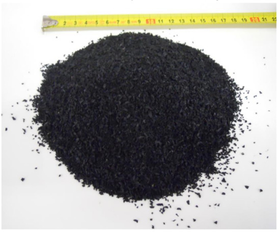
Figure 1.
Waste rubber used in the study.
Table 2.
Selected physicochemical properties of the rubber granulate.
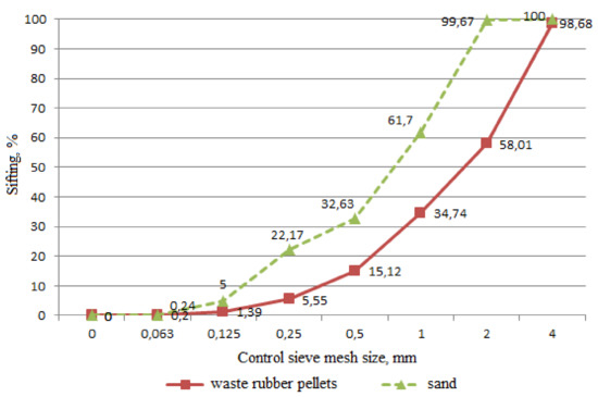
Figure 2.
Particle size curves for sand and waste rubber.
2.2. Methods
The appropriate amount of epoxy resin was mixed thoroughly with the appropriate amount of Z-1 hardener (10 parts/100 g resin) until a homogeneous mixture was obtained. The thusly prepared composition was transferred to a laboratory mixer bowl and mixed with standard sand and a suitable amount of waste rubber granules, maintaining uniform mixing time of 5 minutes and constant mixer rotation. The finished mortar was placed in steel molds with dimensions of 40 × 40 × 160 mm, 60 × 60 × 5 mm and 300 × 300 × 10 mm, assuming that the obtained samples will be used during strength, permeability and thermal conductivity tests respectively. For the curing process to take place, the samples were left for 7 days under laboratory conditions. After this time, individual tests were performed.
2.2.1. Flexural and Compressive Strength
Flexural strength and compressive strength tests were carried out in strength machines equipped with appropriate inserts, on samples with dimensions 40 × 40 × 160 mm in the case of flexural strength and on the halves of these samples for compressive strength, according to PN-EN 196-1: 2006 [38].
2.2.2. Bulk Density
After seven days of aging the samples in laboratory conditions, their masses were determined. Based on the measured dimensions, the volumes of the samples were calculated. Bulk density was calculated based on Formula (1).
where:
- —bulk density, g/cm3
- m—mass of the sample, g
- v—volume of the sample, cm3
2.2.3. Water Absorption
The test was carried out in accordance with PN-EN ISO 62: 2008 [39]. After drying the samples for 24 h at 50 ± 2 °C their constant weight was determined, and they were weighed and then placed in a container with distilled water at 23 ± 2 °C. Water absorption was determined by immersing the samples and weighing them at specific intervals (1–7 days, 2 weeks). In each of these intervals the samples were removed from the water and, after surface water was removed, they were weighed to the nearest 0.1 mg. For each sample, the percentage change in mass (c) in relation to the mass before immersion, based on Formula (2) was calculated:
where: m1—is the mass of the sample expressed in milligrams (mg), after the initial drying, before immersion in water, m2—is the mass of the sample expressed in milligrams (mg), after a specified duration of immersion in water.
The final result is expressed as the arithmetic mean of three values obtained for the three samples, after the same duration of immersion.
2.2.4. Thermal Insulation
As part of the thermal insulation test, the thermal conductivity λ was tested in accordance with EN 12664 [40] using the NETZSCH HFM436 plate device on 300 × 300 × 10 mm samples. The sample was placed between two plates of a calibrated device at given temperatures. After obtaining the equilibrium, the program determined the value of thermal conduction coefficient based on the Fourier’s law, similarly as described in [41]. The temperature difference in the sample was ΔT = 20 K, and the average temperature = 15 °C. The accuracy of the apparatus was ± 1.0 to 3%, while the reproducibility was about ± 0.5%. To assess the suitability of the composite in terms of the practical use of its good thermal insulation properties, numerical simulations were carried out regarding the temperature distribution in part of a building structure. Simulations were carried out for a fragment of a building structure containing a reinforced concrete ceiling slab with a balcony (which is an element of the thermal bridge in the analysis) and a wall with a brick structure. The construction of the numerical model, the layering system and construction solutions were adopted on the basis of the structure of partitions in already existing facilities (e.g., historic tenement houses). In this type of building, the most visible and troublesome problem is the condensation of water vapor in the building partitions.
The following geometry of the numerical model was adopted:
- Layers of the wall:
- external plaster—2 cm (material diversified in variants 1–4),
- wall construction—a 51 cm wall made of full ceramic brick
- 2 cm internal cement and lime plaster.
- Layers of the internal ceiling:
- inner floor—2 cm ceramic tiles on adhesive
- 5 cm cement screed,
- 5 cm chip-cement board,
- ceiling construction—10 cm reinforced concrete slab,
- 2 cm cement and lime plaster.
- Layers of the external balcony:
- 2 cm external floor (material diversified in variants 1–4),
- ceiling construction—10 cm reinforced concrete slab,
- 2 cm cement and lime plaster.
Simulation calculations were carried out for four calculation options:
Variant 1: The balcony surface is covered with ceramic tiles, the outer surface of the wall is finished with cement and lime plaster.
Variant 2: The balcony surface is covered with the designed composite, the outer surface of the wall is finished with cement and lime plaster.
Variant 3: The balcony surface is covered with ceramic tiles, the outer surface of the wall is finished with heat-insulating plaster.
Variant 4: The balcony surface is covered with the designed composite, the outer surface of the wall is finished with heat-insulating plaster.
In selected variants of calculations, reference was made to existing structures for construction of historic tenements in which traditional cement-lime plasters were used. A comparison of the composite with respect to this material group was made to assess whether the use of the proposed mortar is reasonable in practice. The composite containing the highest percentage of waste in relation to aggregate in comparison to the classical epoxy mortar is a considerably more advantageous solution in terms of thermal insulation (decreasing the thermal conduction coefficient with increasing the share of waste.
The geometric model created was divided into a grid of finite elements. Eight nodes in the shape of cuboids were adopted. The size of the single finite elements was varied due to different thicknesses of the layers in the analyzed structure. The geometry of the model is shown in Figure 3. The material used in the balcony floor was also adopted as the finish of the balcony slab front and the pedestal with a height of 10 cm. Table 3 presents the technical parameters of materials that were used during the construction of the numerical model in variants from 1 to 4.
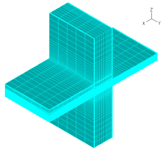
Figure 3.
The geometry of the numerical model after creation of a finite element mesh.
Table 3.
Technical specifications of the materials used in the construction of the numerical model.
It was assumed that in the room adjacent to the analyzed structure the air temperature is +20 °C. Climatic data for the Typical Meteorological Year (TMY) were applied, for the location of Rzeszów-Jasionka, Poland. The convection and radiation processes were modelled on the external and internal surfaces of the structure, and calculations were carried out for the seven-month period of the heating season.
3. Results and Discussion
After the tests, the results obtained were recorded in a STATISTICA worksheet. Average values and measures of dispersion were determined for the designated parameters.
Using the Nonlinear estimation module available in the program, the function graphs shown in Figure 4, Figure 5, Figure 6, Figure 7 and Figure 8 were adjusted to the empirical data.
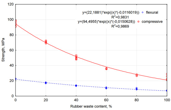
Figure 4.
Graphs of functions describing the dependence of flexural and compressive strength on the percentage share of waste in the mortar.
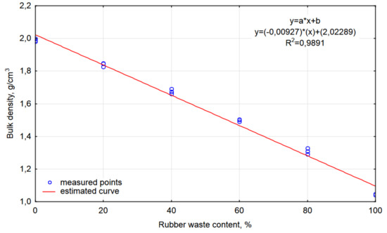
Figure 5.
Graph of the function describing the dependence of bulk density on the percentage share of waste in the mortar.
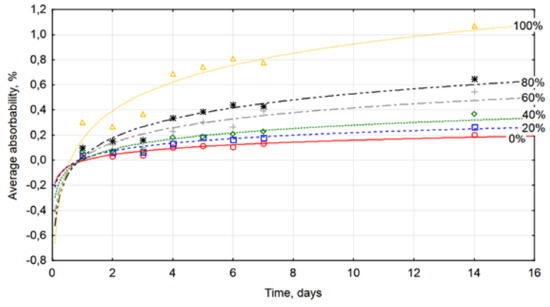
Figure 6.
Graphs of functions describing the dependence of water absorption on the duration of immersion in water.
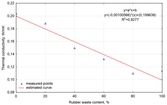
Figure 7.
Graph of the function describing the dependence of the heat transfer coefficient on the percentage share of waste in the mortar.
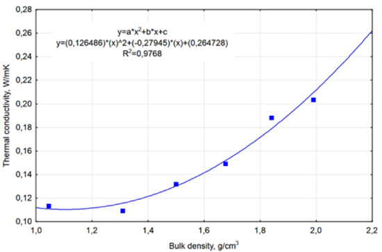
Figure 8.
Graph of the function describing the dependence of the thermal conduction coefficient on the bulk density of the mortar samples.
3.1. Flexural and Compressive Strength
Graphs of the dependence of flexural and compressive strength on the percentage share of waste rubber in the composite are shown in Figure 4.
Visual assessment of the distribution of measurement points on the graphs suggests that the results of the flexural strength and compressive strength tests can fit an exponential function model approximation of the general Formula (3):
In the case of both tested strengths, this model well describes the empirical data, as evidenced by the high values of the coefficients of determination (R2 > 0.98).
Both the flexural strength and compressive strength decrease with increasing content of the waste rubber. Similar relations were noted by Jafari and Toufigh [25]. Based on the SEM tests, these authors stated that the introduction of rubber waste into the concrete mix causes a weakening of the bond at the resin-aggregate interface, thus increasing the porosity of the samples and reducing their mechanical properties. The lowest values of the determined parameters were noted at 100% substitution of aggregate with waste material. The average strength values were 7.12 MPa and 25.07 MPa for flexural and compressive strength, respectively. In relation to samples without the addition of a modifier, for flexural strength a decrease of 15.43 MPa, or as much as 68.4%, was noted. Compressive strength decreased even further, by 73.5% (69.66 MPa). The results obtained with 100% substitution of aggregate by waste are similar to the strength of cement mortars and do not discredit resin composites in the area of their applications.
3.2. Bulk Density
The bulk density of epoxy mortars containing waste rubber decreases with increasing modifier content, as illustrated in Figure 5.
It can be assumed that this decrease is linear, the resulting determination coefficient was R2 = 0.9891. The bulk density decreased from the value of 1.99 g/cm3, in the case of samples without the addition of waste rubber, to the value of 1.04 g/cm3 for mortars with 100% content of the modifier. Thus, the measured parameter decreased by almost 50%. The use of waste material significantly reduced the weight of the composite. This fact is of great importance due to the application possibilities of the composite, for example for the preparation of prefabricated elements used, e.g., in road and bridge drainage systems.
3.3. Water Absorption
Figure 6 shows the functions of the trend describing the change in water absorption in mortar samples containing different amounts of modifier as a function of exposure time. The logarithmic function of form (4) was fitted to the data:
Table 4 presents the coefficients of regression equations and coefficients of determination obtained for mortars with different waste rubber content.
Table 4.
Summary of coefficients of regression equations and coefficients of determination for mortars with different waste rubber content, obtained after 14 days exposure in water.
The coefficients of determination ranging from 0.8198 to 0.9167 confirm that the adopted model is statistically significant and properly matched to the measurement results. The mortars’ water absorption increases slightly as the duration of exposure in water increases (Figure 6). This is due to the fact that the pores of the material can be occupied by water molecules, which causes an increase in the mass of samples. After two weeks, this process is practically finished, which is shown by the final flattened part of the graph. In addition, it can be observed that water absorption increases with increasing degree of substitution of sand waste. The value of 0.26% obtained after 14 days of exposure of samples containing 20% modifier, is similar to the results obtained by the team of G. Ahmetli [42], studying similar composites. The highest permeability values were recorded for samples containing 100% waste. In this case, this parameter was 1.07%. It should be noted that this value is still significantly lower than the permeability of cement mortars. For examples, Bisht and Ramana [20] obtained permeability at the level of 3.21% with 5.5% substitution of aggregates with waste rubber in cementitious concrete.
3.4. Thermal Insulation
The modifications carried out had a positive effect on the thermal performance of the composite, which was determined by programming the plate apparatus for the average temperature of 15 °C and the temperature difference in the sample equal to 20 K. With an increase in waste rubber content, the thermal conductivity λ decreases, as shown in Figure 7. The adjusted regression function here may also take the form of a linear function. The obtained coefficient of determination was R2 = 0.9277, which indicates a good fit of the line to the measurement results. The value of the heat transfer coefficient λ decreased from the value of 0.204 W/(m·K) obtained for unmodified mortars to 0.114 W/(m·K) in the case of 100% substitution sand with waste. The decrease was therefore over 44%. In the case of mortars containing 80% waste rubber, the difference is even greater, 46.6%.
The relationship between the thermal conductivity and bulk density can be represented by a function that takes the form of a second-degree polynomial, which is presented in Figure 8. The good fit of the parabola to the empirical data testifies to a high coefficient of determination, in this case 0.9768.
The designed composite is a material that better insulates thermally in comparison to traditional materials used for making floors and finishing layers used on patios, balconies and verandas. The value of the thermal conduction coefficient λ for the designed composite obtained during laboratory tests was in the range of 0.11–0.20 W/(m·K)—depending on the proportion of components used in the composite. Table 5 shows for comparison the value of the coefficient λ for other materials with similar purpose.
Table 5.
Values of coefficients λ for selected finishing materials.
From the information given in Table 5, it can be seen that in the group of materials dedicated to finishing usable surfaces—the designed composite belongs to the group that is best insulated thermally but does not reach a level comparable with thermal insulation materials.
In the case of modern buildings, in which balcony and patio slabs are thermally insulated (e.g., with extruded polystyrene)—the type of floor adopted does not significantly affect the temperature distribution in the external wall adjacent to the panel. In this case, the thickness of the designed thermal insulation is significant. The situation is different in historic buildings. Buildings of this type come from a period in which thermal insulation was not often used. Currently, conservation restrictions often do not allow the use of additional layers of thermal insulation on the exterior surfaces of such building elements. In this case, the solution allowing for a more favorable temperature distribution in the thermal bridges is the use of heat-protective plasters on the surface of the walls and materials with a low conduction coefficient λ (e.g., the designed composite) as the floor layers on the patios, balconies and other external usable surfaces. Therefore, in the numerical simulation of thermal processes, an arrangement of layers in the barriers was adopted based on solutions used, among others, in historic tenement houses (variants 1–4).
Figure 9 shows the temperature distribution in the partition for two extreme calculation variants (variants 1 and 4). The figure refers to the time step in the analysis in which the lowest temperature was obtained on the inner wall surface—this corresponds to the date of December 27. The temperature of the entire model ranges from −16 °C to +20 °C.
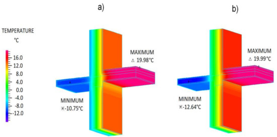
Figure 9.
Temperature distribution in the model at the time of the lowest temperature on the inner wall surface; (a) variant 1, (b) variant 4.
It can be noticed that in the case of variant 4—the lowest temperature value on the external side is lower by 1.89 °C in relation to the minimum temperature for variant 1. This is the effect of a better insulated thermal bridge zone in the case of variant 4 due to the use of the designed composite and heat-protective plaster.
To show the results concerning the internal surface of the partition, a vertical cross-section was created for all of the variants by a model in the internal plaster layer, just next to its internal surface (Figure 10). The temperature of this part of the model ranges from +10 °C to +20 °C.
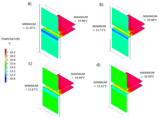
Figure 10.
Temperature distribution in the model on the internal surfaces of the partitions at the time of the lowest temperature on the inner wall surface; (a) variant 1, (b) variant 2, (c) variant 3, (d) variant 4.
In the case of a classic exterior surface finish with cement and lime plaster, the use of the designed composite as a balcony finishing layer does not significantly affect the temperature distribution on the internal surface of the model. The difference in internal surface temperature between variant 1 and variant 2 is only 0.26 °C in favor of the variant with the composite. After applying a thermal insulation plaster on the outer surface of the wall—the effect of the composite as a surface finish on the surface temperature of the inner wall increases significantly. The temperature difference of the internal wall surface between variant 3 and variant 4 is already 0.55 °C in favor of the variant with the composite. Comparing variant 1 with variant 4, it turns out that the temperature difference obtained in favor of variant 4 is as high as 1.77 °C.
The results of the numerical analysis showed that the use of the designed composite as a layer replacing the surface finish of balconies in the form of ceramic tiles improves the temperature distribution in the structural system analyzed, which allows in particular cases to avoid condensation on the inner surface of the barrier in extremely unfavorable conditions. Figure 11 shows the temperature distribution on the internal surface for the total period of the numerical analysis, in which the lowest temperature values occur on the inner wall surface. This is the place most exposed to condensation of surface water vapor. Figure 11 shows the results obtained for four calculation options in accordance with the assumptions described earlier. The horizontal line shows the limit value of the internal surface temperature below which water vapor on the surface of the partition can condense. The results presented in the graph show that only in the case of variant 4 did the temperature of the inner surface in the coolest place not fall below the surface condensation temperature for the full winter period.
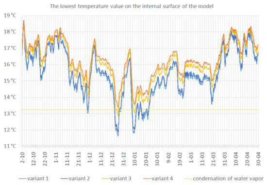
Figure 11.
The lowest temperature values on the internal surface of the model for the four analyzed variants.
In the other variants (1–3) time periods for which the surface temperature was lower than the temperature of condensation occur. It should be noted that if such condensation occurs the layers in the partition become wet. The effect of such action is a lowering of the temperature of the internal surface, because the thermal resistance of the partition decreases. Changes in the technical parameters resulting from the effects of condensation have not been included in the analysis; however, it should be expected that their influence on additional partition degradation may be significant.
The results presented relate to a specific case of construction and cannot lead to the conclusion that the use of the designed composite for traditional flooring for the external usable surfaces of a building will improve the thermal parameters of a partition in a significant way in each calculation case. However, one can put forward the thesis that in terms of thermal insulation the proposed composite meets the expectations in the group of materials for finishing external surfaces, and in this respect the vast majority of cases will not be worse than traditional materials used to finish external usable surfaces in buildings. However, in special cases, in combination with the application of thermal insulation plasters on the surface of the walls, it may result in improvement of the temperature in the thermal impact zone to a significant degree.
The presented analysis indicates the beneficial effect of the use of composites with admixtures of waste rubber on thermal parameters in specific structural solutions. The combination of good thermal insulation parameters with minimal water absorption means that the designed composite is a material that can be offered as an alternative to traditional surface finishing solutions, with particular emphasis on external usable surfaces (patios, balconies and verandas). In the case of historic buildings, the decision to use the proposed composite must be made by the conservator of the object management. He should be able to assess whether the structure and form of the proposed composite will be appropriate for the implementation of external facade elements. To make the correct assessment, it is necessary to make composite samples with the appropriate structure and color.
4. Conclusions
Rubber from old car tires is finding more and more use as a reusable material. One option is to convert tires into granules, which can be a substitute for aggregates in concrete-like building composites. The benefits of this come from a reduction in the number of tires stored—which translates to a significant reduction in environmental pollution. The research described in this article led to the following conclusions:
- Substitution of aggregates in epoxy mortars results in a lowering of the strength parameters; however, even 100% replacement of sand with granulated rubber granules allows us to obtain a composite that can compete with cement mortars.
- The use of a modifier causes a significant reduction in the mass of composites. The bulk density of control mortar samples is almost twice as high as mortars in which the waste completely replaces the sand.
- An analogous relationship was noted when the feature tested was the heat transfer coefficient λ. The composite with 100% content of waste is characterized by thermal insulation comparable to heat protective mortars.
- The composites obtained as a result of the modification also have very low permeability to water.
- On the basis of numerical simulation, the possibility of applying the mortar was demonstrated, e.g., as a finishing layer for balconies and terraces.
Author Contributions
Conceptualization, B.D.; Data curation, B.D.; Formal analysis, B.D. and P.M.; Funding acquisition, L.L.; Investigation, B.D.; Methodology, B.D. and P.M.; Project administration, L.L.i; Resources, B.D. and P.M.; Supervision, L.L.; Validation, B.D., L.L. and P.M.; Visualization, B.D. and P.M.; Writing—original draft, B.D. and P.M.; Writing—review & editing, B.D.
Funding
This research received no external funding.
Conflicts of Interest
The authors declare no conflict of interest.
References
- Czarnecki, L. Sustainable Concrete; Is Nanotechnology the Future of Concrete Polymer Composites. Adv. Mat. Res. 2013, 687, 3–11. [Google Scholar] [CrossRef]
- Czarnecki, L.; Justnes, H. Sustainable and Durable Concrete. Cem. Lime Concr. 2012, 6, 341–362. [Google Scholar]
- Czarnecki, L.; Kaproń, M.; Piasecki, M.; Wall, S. Sustainable construction means construction of future. Inżynieria i Budownictwo 2012, 1, 18–21. [Google Scholar]
- Vila, A.; Péreza, G.; Soléa, C.; Fernánez, A.I.; Cabeza, L.F. Use of rubber crumbs as drainage layer in experimental green roofs. Build. Environ. 2012, 48, 101–106. [Google Scholar] [CrossRef]
- Rincóna, L.; Coma, J.; Péreza, G.; Castella, A.; Boerb, D.; Cabeza, L.F. Environmental performance of recycled rubber as drainage layer in extensive green roofs. A comparative Life Cycle Assessment. Build. Environ. 2014, 74, 22–30. [Google Scholar] [CrossRef]
- Sienkiewicz, M.; Janik, H.; Borzędowska-Labuda, K.; Kucińska-Lipka, J. Environmentally friendly polymer-rubber composites obtained from waste tyres: A review. J. Clean. Prod. 2017, 147, 560–571. [Google Scholar] [CrossRef]
- Rahimi R., S.; Nikbin, I.M.; Allahyari, H.; Habibi T., S. Sustainable approach for recycling waste tire rubber and polyethylene terephthalate (PET) to produce green concrete with resistance against sulfuric acid attack. J. Clean. Prod. 2016, 126, 166–177. [Google Scholar] [CrossRef]
- Pyskło, L.; Parasiewicz, W. Odzysk i recykling wyrobów gumowych. Forum recyklingu POLEKO 2004. Recykling 2004, 11. Available online: http://e-czytelnia.abrys.pl/recykling/2004-11-140/materialy-seminaryjne-1714/odzysk-i-recykling-wyrobow-gumowych-4224 (accessed on 24 January 2019). (In Polish).
- Gronowicz, J.; Kubiak, T. Recykling zużytych opon samochodowych. Problemy Eksploatacji 2007, 2, 5–18. (In Polish) [Google Scholar]
- Fraile-Garcia, E.; Ferreiro-Cabello, J.; Defez, B.; Peris-Fajanes, G. Acoustic Behavior of Hollow Blocks and Bricks Made of Concrete Doped with Waste-Tire Rubber. Materials 2016, 12, 962. [Google Scholar] [CrossRef]
- Aliabdo, A.A.; Abd Elmoaty, A.E.M.; AbdElbaset, M.M. Utilization of waste rubber in non-structural applications. Constr. Build. Mater. 2015, 91, 195–207. [Google Scholar] [CrossRef]
- Zhang, B.; Poon, Ch.S. Sound insulation properties of rubberized lightweight aggregate concrete. J. Clean. Prod. 2018, 172, 3176–3185. [Google Scholar] [CrossRef]
- Corredor-Bedoya, A.C.; Zoppi, R.A.; Serpa, A.L. Composites of scrap tire rubber particles and adhesive mortar—Noise insulation potential. Cem. Concr. Compos. 2017, 82, 45–66. [Google Scholar] [CrossRef]
- López-Zaldívar, O.; Lozano-Díez, R.; Herrero del Cura, S.; Mayor-Lobo, P.; Hernández-Olivares, F. Effects of water absorption on the microstructure of plaster with end-of-life tire rubber mortars. Constr. Build. Mater. 2017, 150, 558–567. [Google Scholar] [CrossRef]
- Lanzón, M.; Cnudde, V.; De Kock, T.; Dewanckele, J. Microstructural examination and potential application of rendering mortars made of tire rubber and expanded polystyrene wastes. Constr. Build. Mater. 2015, 94, 817–825. [Google Scholar] [CrossRef]
- Thomas, B.S.; Gupta, R.Ch. A comprehensive review on the applications of waste tire rubber in cement concrete. Renew. Sust. Energ. Rev. 2016, 54, 1323–1333. [Google Scholar] [CrossRef]
- Gupta, T.; Siddique, S.; Sharma, R.K.; Chaudhary, S. Effect of elevated temperature and cooling regimes on mechanical and durability properties of concrete containing waste rubber fiber. Constr. Build. Mater. 2017, 137, 35–45. [Google Scholar] [CrossRef]
- Guelmine, L.; Hadjab, H.; Benazzouk, A. Effect of elevated temperatures on physical and mechanical properties of recycled rubber mortar. Constr. Build. Mater. 2016, 126, 77–85. [Google Scholar] [CrossRef]
- Medina, N.F.; Medina, D.F.; Hernández-Olivares, F.; Navacerrada, M.A. Mechanical and thermal properties of concrete incorporating rubber and fibres from tyre recycling. Constr. Build. Mater. 2017, 144, 563–573. [Google Scholar] [CrossRef]
- Bisht, K.; Ramana, P.V. Evaluation of mechanical and durability properties of crumb rubber concrete. Constr. Build. Mater. 2017, 155, 811–817. [Google Scholar] [CrossRef]
- Barbuta, M.; Diaconu, D.; Serbanoiu, A.A.; Burlacu, A.; Timu, A.; Gradinaru, C.M. Effects of Tire Wastes on the Mechanical Properties of Concrete. Procedia Eng. 2017, 181, 346–350. [Google Scholar] [CrossRef]
- Sofi, A. Effect of waste tyre rubber on mechanical and durability properties of concrete—A review. Ain Shams Eng. J. 2017. [Google Scholar] [CrossRef]
- Barbuta, M.; Harja, M.; Ciobanu, G. Mechanical properties of polymer concrete containing tire waste power. J. Food Agric. Environ. 2014, 12, 1185–1190. [Google Scholar]
- Aoudia, K.; Azem, S.; Hocine, N.A.; Gratton, M.; Pettarin, V.; Seghar, S. Recycling of waste tire rubber: Microwave devulcanization and incorporation in a thermoset resin. Waste Manag. 2017, 60, 471–481. [Google Scholar] [CrossRef] [PubMed]
- Jafari, K.; Toufigh, V. Experimental and analytical evaluation of rubberized polymer concrete. Constr. Build. Mater. 2017, 155, 495–510. [Google Scholar] [CrossRef]
- Czarnecki, L. Polymer concretes. Cem. Lime Concr. 2010, 2, 63–85. [Google Scholar]
- Dębska, B.; Lichołai, L. The effect of the type of curing agent on selected properties of epoxy mortar modified with PET glycolisate. Constr. Build. Mater. 2016, 124, 11–19. [Google Scholar] [CrossRef]
- Lichołai, L.; Dębska, B. The multidimensional response function exemplified by epoxy mortars: Looking for the global extreme. Arch. Civ. Mech. Eng. 2014, 14, 466–475. [Google Scholar] [CrossRef]
- Dębska, B.; Lichołai, L. Resin Composites with High Chemical Resistance for Application in Civil Engineering. Period. Polytech-Civ. 2016, 60, 281–287. [Google Scholar] [CrossRef]
- Lichołai, L.; Dębska, B. A study of the effect of corrosive solutions on selected physical properties of modified epoxy mortars. Constr. Build. Mater 2014, 65, 604–611. [Google Scholar]
- Dębska, B. Modification of Polymer Composites by Polyethylene Terephthalate Waste. In Poly(ethylene Terephthalate) Based Blends, Composites and Nanocomposites; Visakh, P.M., Liang, M., Eds.; Elsevier: Amsterdam, The Netherlands, 2015; p. 195. [Google Scholar]
- Dębska, B.; Lichołai, L. The selected mechanical properties of epoxy mortar containing PET waste. Constr. Build. Mater. 2015, 94, 579–588. [Google Scholar] [CrossRef]
- Dębska, B.; Lichołai, L.; Szyszka, J. Innovative composite on the basis of an aerogel mat with an epoxy resin modified with PET waste and PCM. E3S Web Conf. 2018, 44, 00031. [Google Scholar] [CrossRef]
- Dębska, B.; Lichołai, L. Analysis of Bending Strength of Resin Mortars That Are at Risk of Long-Term Exposure to Environmental Corrosives. IOP Conf. Ser. Earth Environ. Sci. 2017, 95, 042015. [Google Scholar] [CrossRef]
- Dębska, B.; Lichołai, L. Environmental Factors Affecting the Strength Characteristics of Modified Resin Mortars. IOP Conf. Ser. Earth Environ. Sci. 2017, 95, 042016. [Google Scholar] [CrossRef]
- Miąsik, P.; Lichołai, L. The influence of a thermal bridge in the corner of the walls on the possibility of water vapour condensation. E3S Web Conf. 2018, 49, 00072. [Google Scholar] [CrossRef]
- Miąsik, P.; Krasoń, J. Thermal functioning of a transparent barrier equipped with a system of external thermal insulation shields. E3S Web Conf. 2018, 49, 00071. [Google Scholar] [CrossRef]
- PN-EN ISO 196–1:2006. Metody badania cementu—Część 1: Oznaczanie wytrzymałości; Polski Komitet Normalizacyjny: Warshaw, Poland, 2006. (In Polish)
- PN-EN ISO 62:2008.Tworzywa sztuczne—Oznaczanie absorpcji wody; Polski Komitet Normalizacyjny: Warsaw, Poland, 2008. (In Polish)
- EN 12664:2002. Właściwości cieplne materiałów i wyrobów budowlanych—Określanie oporu cieplnego metodami osłoniętej płyty grzejnej i czujnika strumienia cieplnego—Suche i wilgotne wyroby o średnim i małym oporze cieplnym; Polski Komitet Normalizacyjny: Warsaw, Poland, 2002. (In Polish) [Google Scholar]
- Berardi, U.; Naldi, M. The impact of the temperature dependent thermal conductivity of insulating materials on the effective building envelope performance. Energy Build. 2017, 144, 262–275. [Google Scholar] [CrossRef]
- Ahmetli, G.; Gungor, A.; Kocaman, S. Epoxy composites based on inexpensive tire waste filler. AIP Conf. Proc. 2014, 1599, 346. [Google Scholar]
© 2019 by the authors. Licensee MDPI, Basel, Switzerland. This article is an open access article distributed under the terms and conditions of the Creative Commons Attribution (CC BY) license (http://creativecommons.org/licenses/by/4.0/).