Using Network Analysis and BIM to Quantify the Impact of Design for Disassembly

Abstract
:1. Introduction
2. Elaboration of the Method
2.1. Aim and Scope
2.2. Guiding Rules
- The amount of parameters added by the users should remain limited. Therefore, the combination with BIM is considered as a key opportunity in the integration, development and dissemination of the method, as it maximizes the amount of information collected while minimizing the amount of extra information to add manually. This rule facilitates the use of the method and refers to ability.
- A user adding more information should be rewarded. The values taken by default consider the worst-case scenario (i.e., the scenario inducing the higher amount of waste). For instance, a model without information on connections and dependencies considers by default that all connections are irreversible and all elements interdependent, resulting in a high quantity of lost elements. If the user adds more information, the results can only improve. Henceforth, the method can assess preliminary and detailed designs, allowing users to test a design along its development. This second rule refers to trigger and motivation.
- Finally, the DNA method should not rely on a particular BIM software but rather on the general principles of a BIM platform, such as data structure, object oriented-approach and classification of elements. This third rules makes the DNA method independent from proprietary software or quickly evolving tools and increases the ability of the user.
3. Disassembly Quantification Method
3.1. Parameters
- Accessibility: An element is accessible if a worker can reach the element and all its connections. To recover the elements and unfasten the connections, it is necessary to access them physically.
- Transportability: The mass and volume of the element are limited to a maximal value allowing transportability. Possible verifiers are that the element’s weight and element’s dimensions are lower than a certain limit (see Equations (1) and (2)). This limit may vary depending on norms and regulations (maximum weight allowed per worker) or tools and machinery used.Weightelement < Weightlimit(x,y,z)element < (lmax,Lmax,Hmax)
- Resistance factor: A number between 0 and 1 representing the resistance to wear and tear of an element. In further development, other resistance types can be considered. This factor defines the rupture point when two elements linked with an irreversible connection must be separated.
- Weight: This represents the mass of the element.
- Reversibility of connection: This considers if the connection can be unfastened without damaging the elements constituting of the assembly.
- Time to disassemble: This is the time needed to unfasten a reversible connection. It considers the ease of disassembly. Together with additional information, such as the working force need or the type of tools, it will allow the time and price of disassembly to be determined.
- Time to break apart: This is the time needed to break apart a connection, which can be reversible or irreversible.
- Sequential dependence: This parameter considers that buildings elements have various functions. Some of them, such as the structure, are necessary for the building stability, while others are secondary. These relations and interdependencies between elements influence the disassembly sequence. The disassembly sequence is sometimes not the opposite of the assembly sequence. For instance, during construction, the roof could be “assembled” after the windows but does not have to be disassembled before the windows.
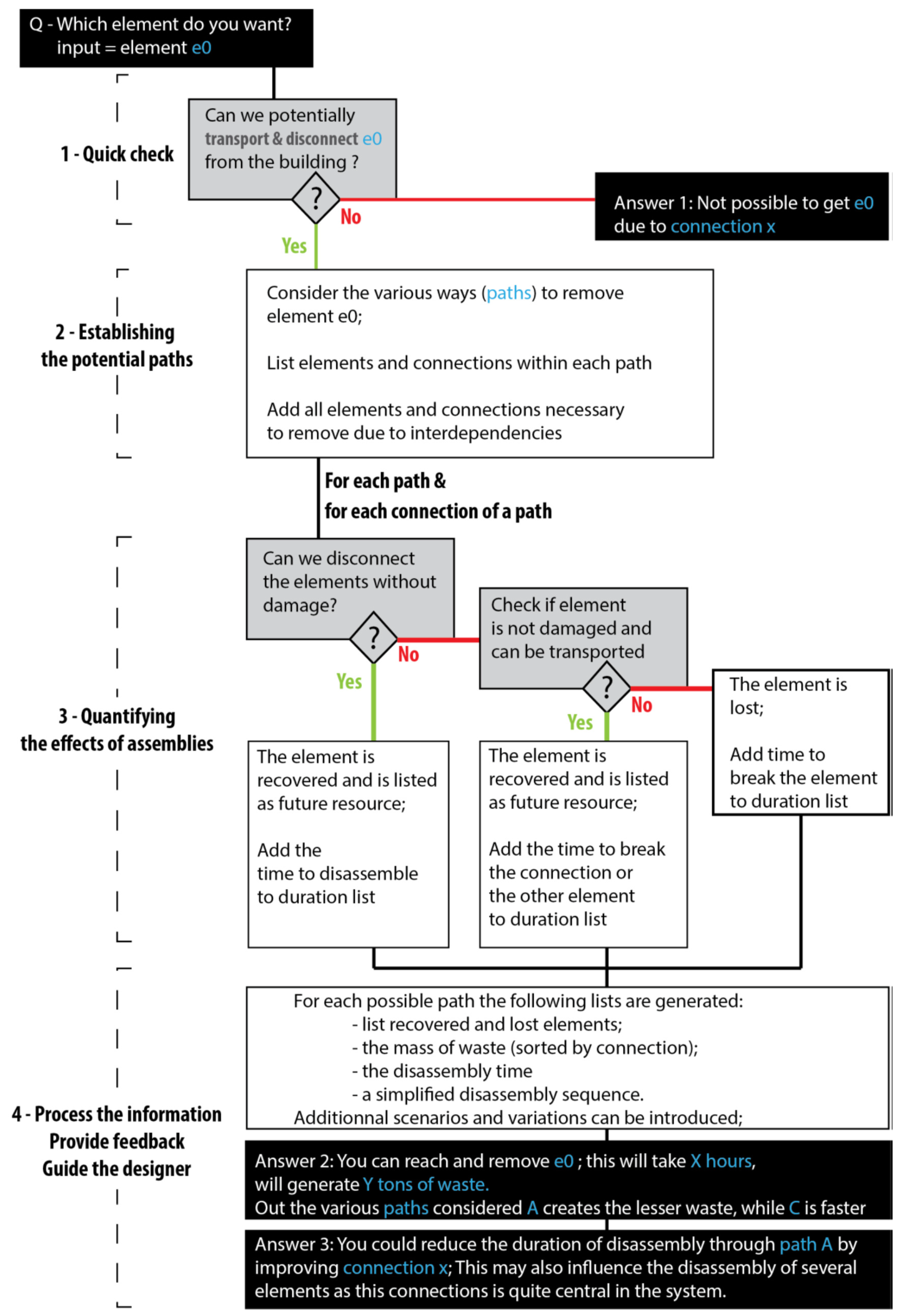
3.2. Flowchart
4. Illustrative Examples
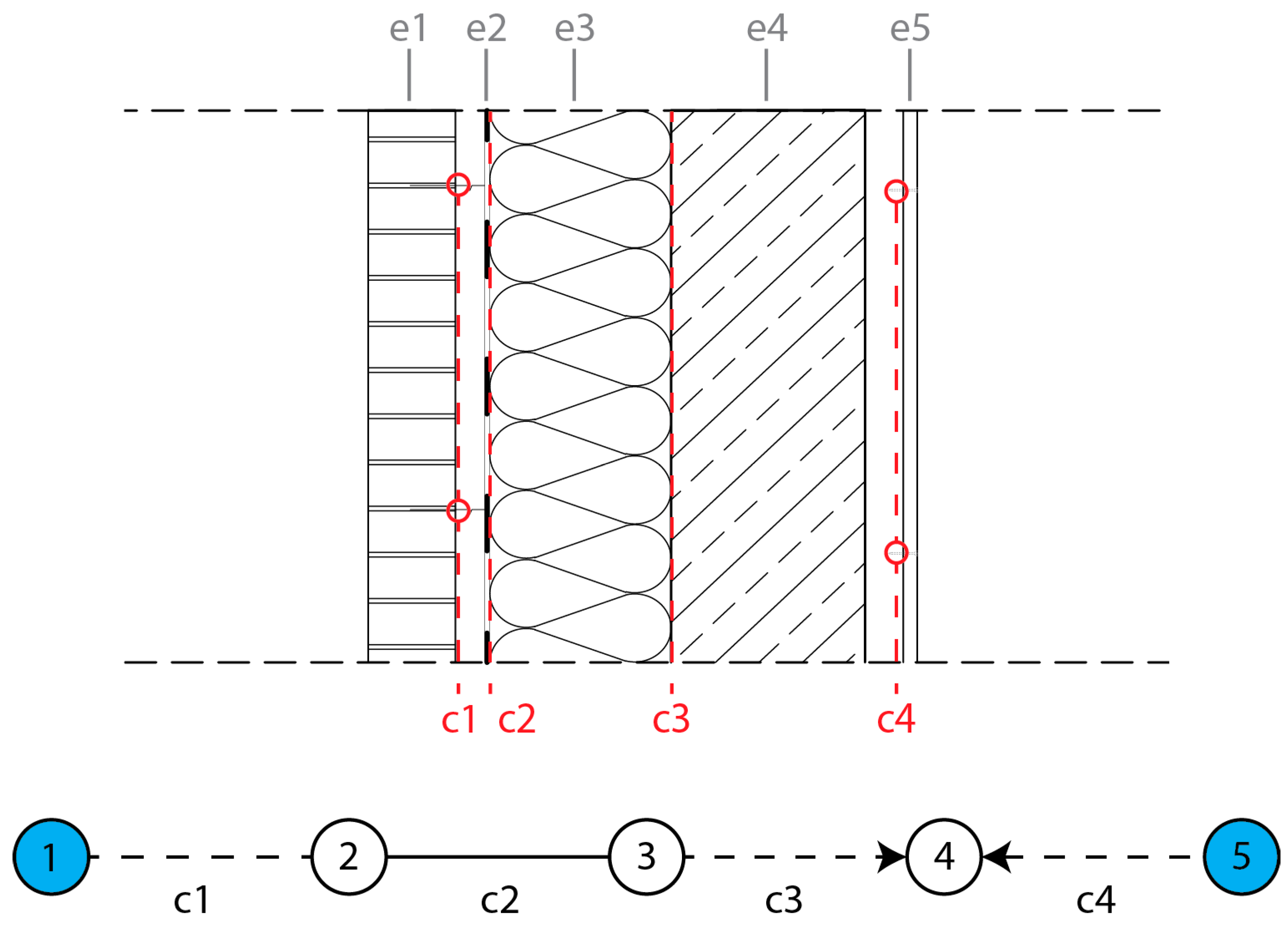
4.1. Façade Wall
- Is e3 transportable? Yes.
- Can each connection with e3 be disconnected? c2 (between e2 and e3) is not reversible. Therefore, the elements’ resistance factors should be compared. Because e3 has a higher resistance factor than e2, e3 will be preserved.
- In path P1: elements e1, e2, e3 and connections c1, c2
- In path P2: elements e5, e4, e3 and connections c4, c3
- In path P1: elements e1, e2, e3 and connections c1, c2, c3
- In path P2: elements e5, e4, e3 and connections c4, c3, c2
- Lost elements: e2 (due to the removal of c2)
- Recovered elements: e1 (due to the removal of c1) + e3 (due to the removal of c3)
- Total duration: Td1 + Tb2 + Td3 = 60 + 220 + 60 = 440 [s]
- Total waste: 2 kg.
4.2. Structural Frame with Techniques and Finishes
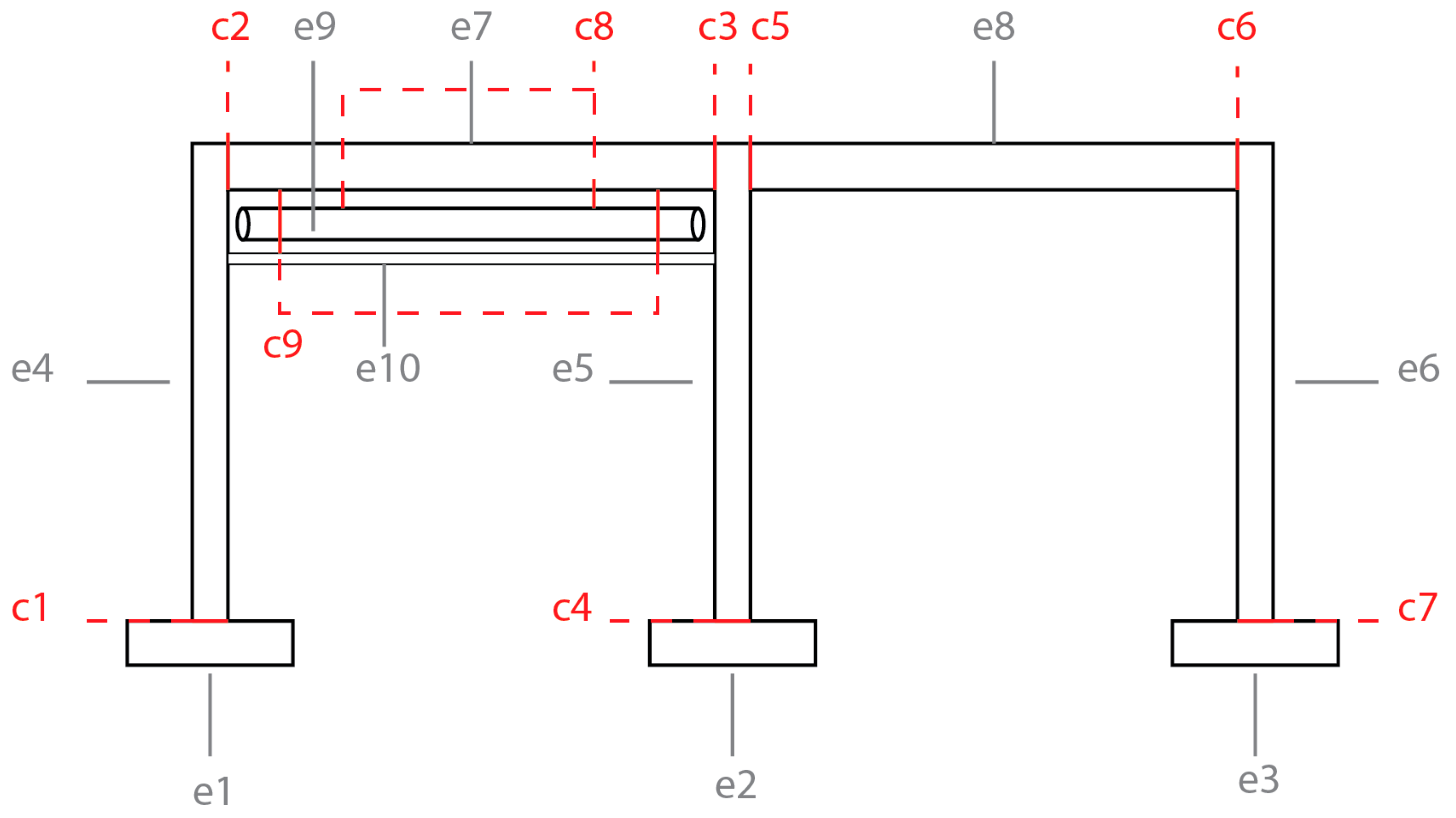
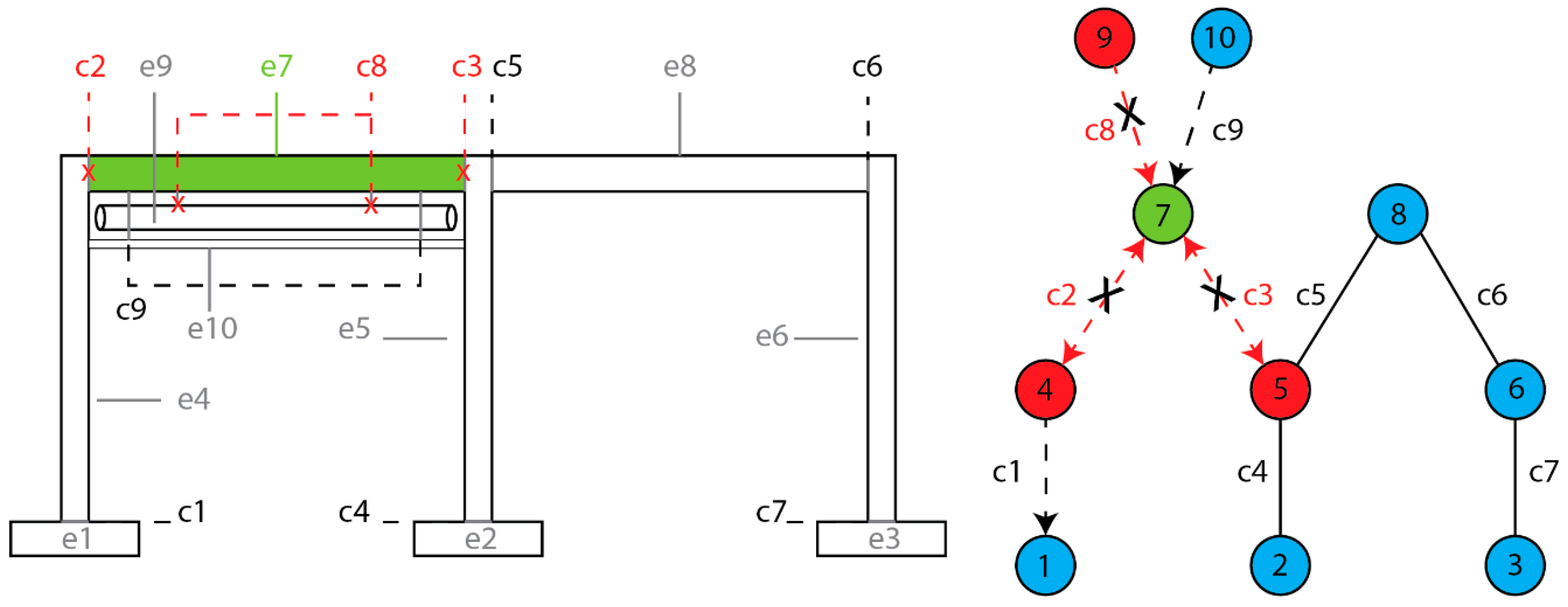
4.2.1. Initial Situation
- Is e7 transportable? Yes.
- Can each connection with e7 be disconnected? Yes.
- Path P1: elements e7, e10 and connection c9
- Path P2: elements e7, e4 and connection c2
- Path P3: elements e7, e5 and connection c3
- elements e9, e4, and e5 (i.e., they are considered as dependent on e7)
- connections c8, c2, c3
- elements e10, e4, e1, e4, e2, e5, e3, e6 e8, e9, e7
- connections c9, c1, c2, c7, c4, c6, c5, c3, c8
- The final disassembly sequence is not realistic compared to the nature of the elements (beams and columns). In this case, the DNA method always considers that the disassembled objects are supporting the others. In that case, the support (column) is considered as something that needs to be removed prior to the beam (hosted element); this does not come directly from the method but from missing information and data.
- In future development, more nuance can be applied to the default value by considering additional metadata stored within BIM objects, such as the type of object (e.g., beam and column) and their location (e.g., level and host).
- The distinction between sequential and parallel disassembly is not made and results in longer disassembly time. Indeed, the method calculates the number of working hours needed without considering if workers can work in parallel. Hence, future alternatives to distinguish sequential and parallel disassembly can be considered, although this has not been identified as a necessary feature.
- Interdependencies are needed for more detailed investigations and results.
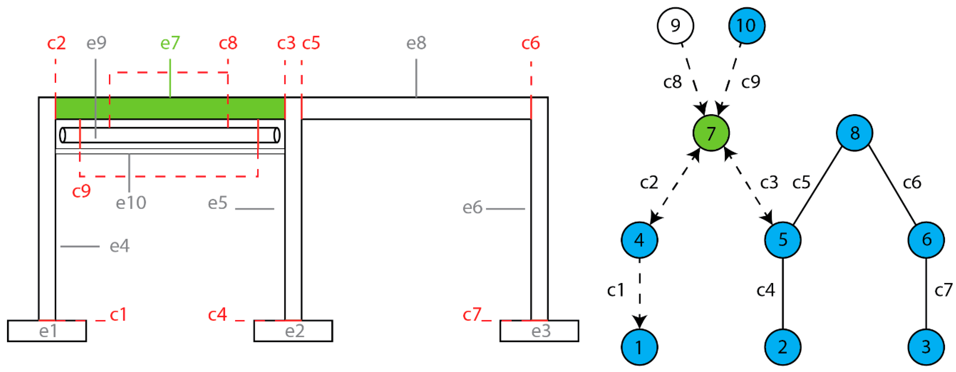
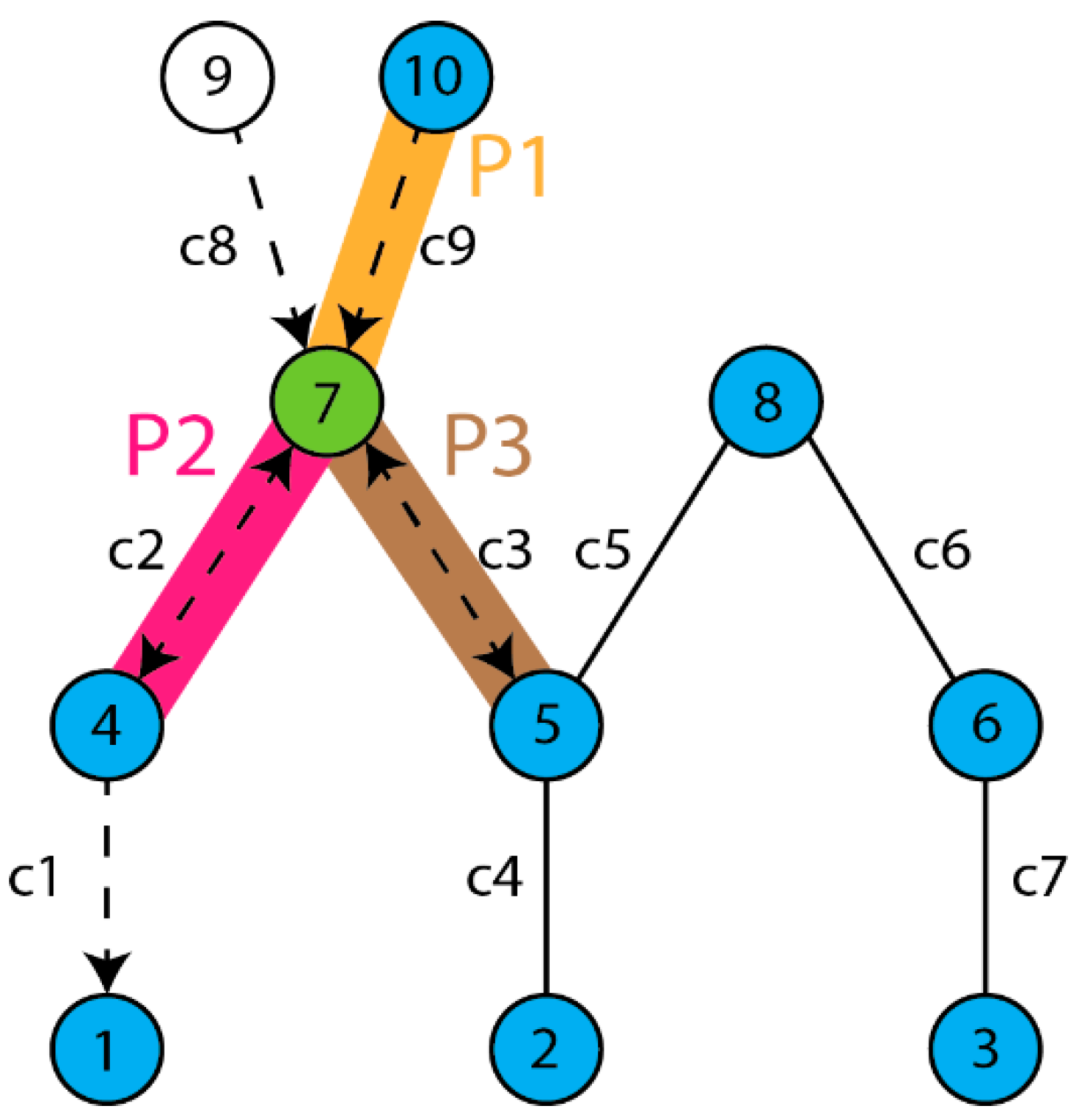
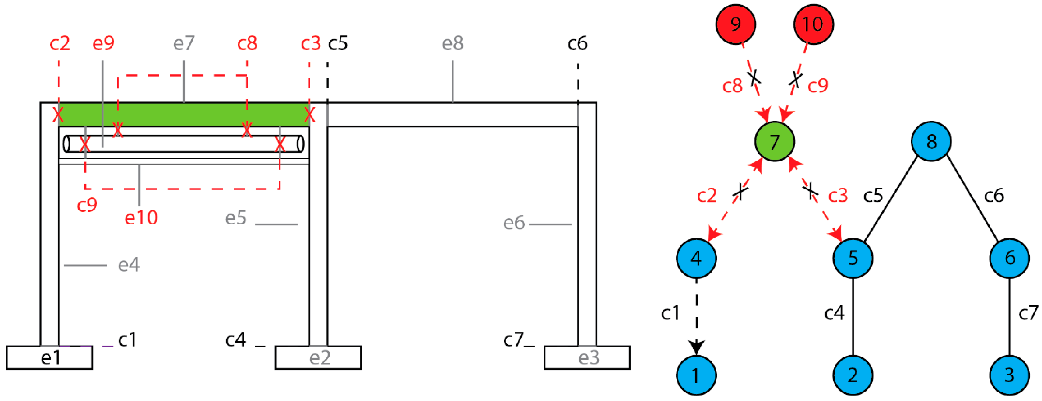
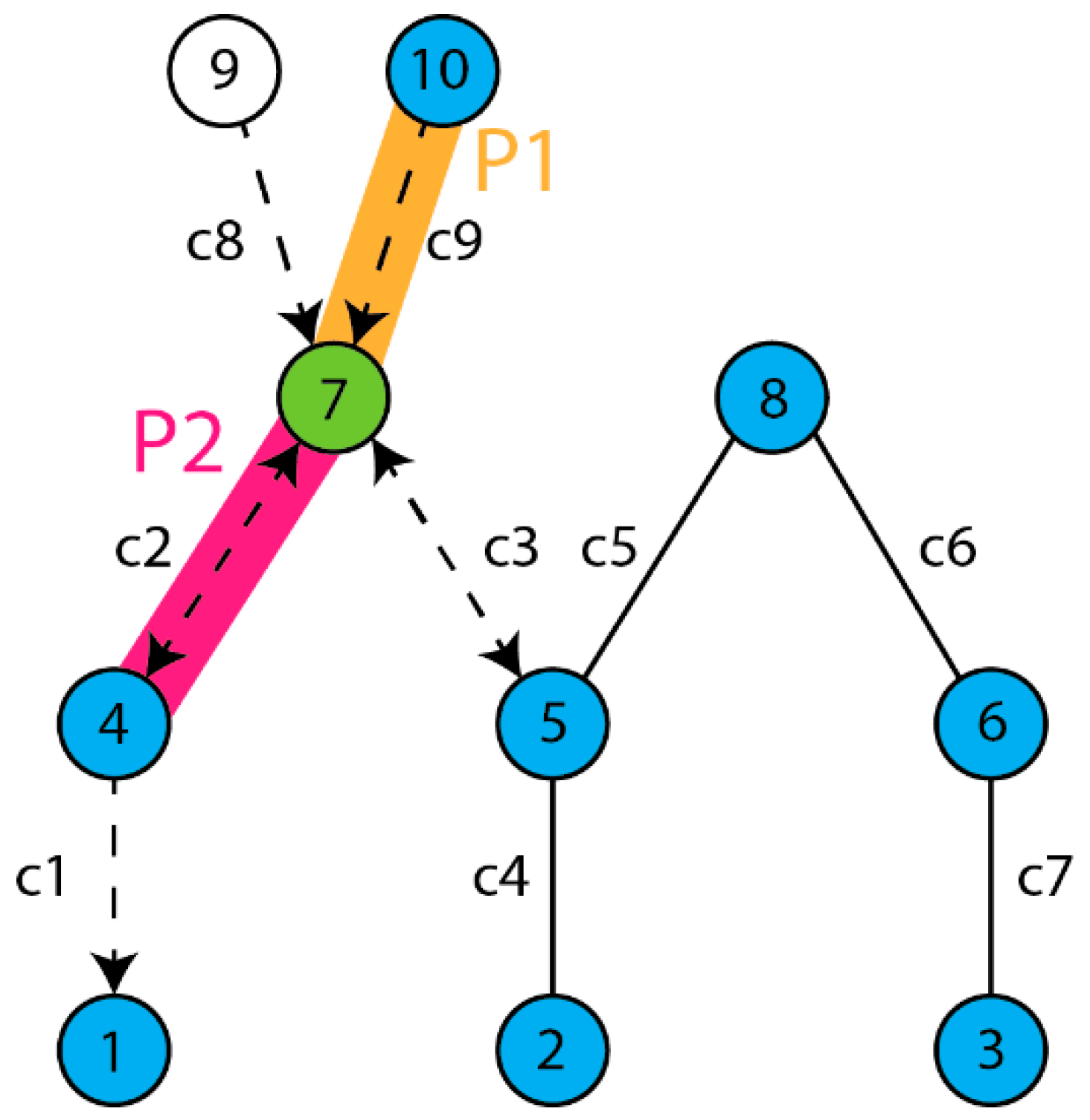
4.2.2. Path Determination on a Simplified Case Considering Dependencies
- In path P1: elements e7, e10 and connection c9
- In path P2: elements e7, e4 and connection c2
- In path P1: elements e10, e9, e7 and connections c9, c8, c3, c2 (Figure 9)
- In path P2: elements e4, e10, e9, e7 and connections c9, c8, c3, c2, c1
- Following the second guiding rule, this case considers the (structural) interdependence between elements, which therefore reduces the amounts of elements to be removed (compared to case 1). By adding extra information, the user is rewarded with a reduction of the disassembly time and waste generated.
- Two different paths show different results, which illustrates that the method can consider and distinguish various paths. This also represents a huge opportunity because, while a manual method might be more efficient and effective for a reduced number of paths, the added value of the DNA tool will be in the evaluation of several paths and disassembly sequences as a whole.
- No distinction is made between e9 and e10 although, in reality, e10 must be removed prior to e9. This shows the necessity to add a factor considering the “dependence regarding the accessibility of the element”. Indeed, connection c8 and element e9 are only accessible after the removal of e10. This can be made by adding accessibility interdependencies (similar way to structural dependency) as inputs, either as a parameter in the model, a cell in a calculation sheet, or through a dependency graph.
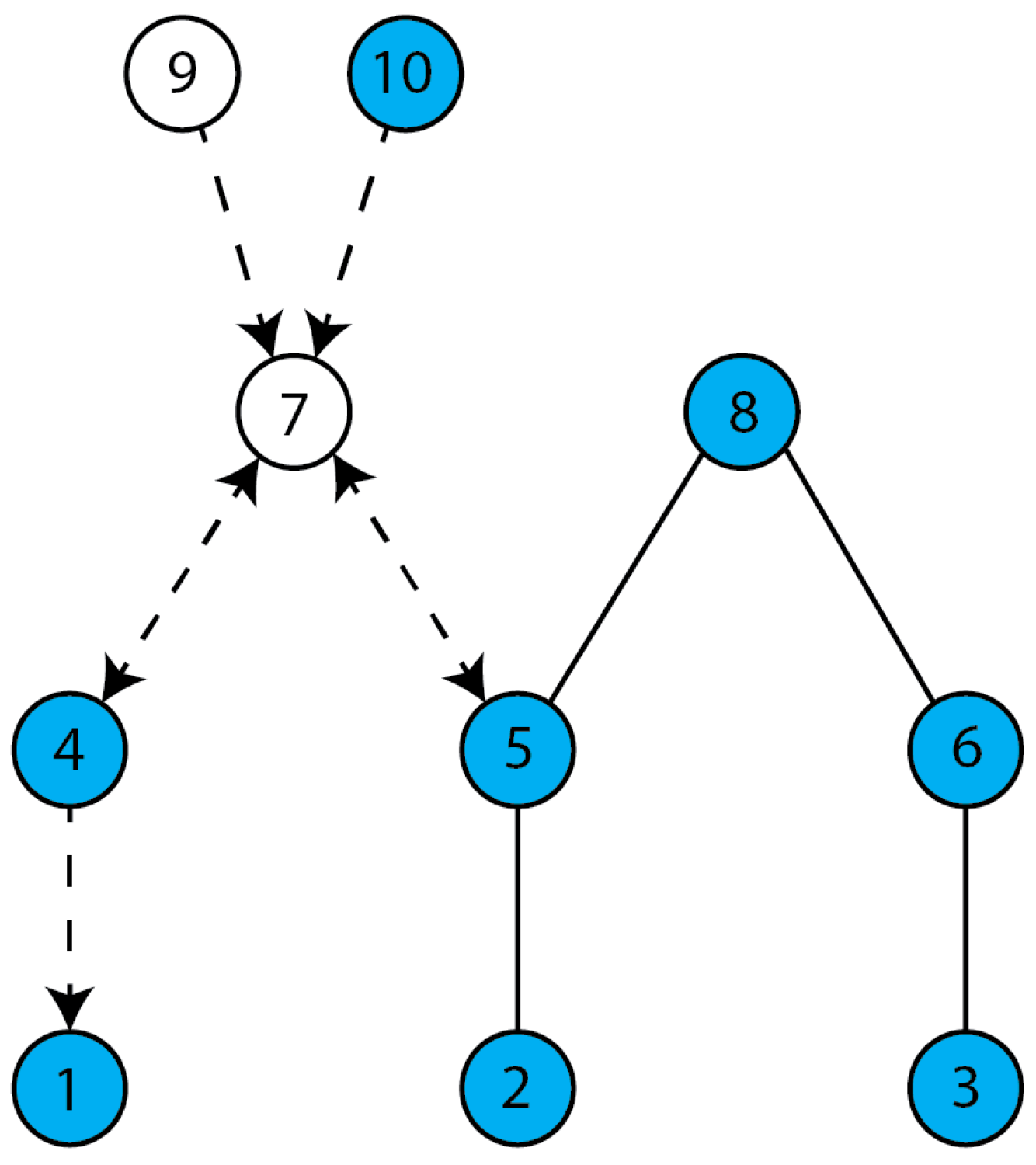
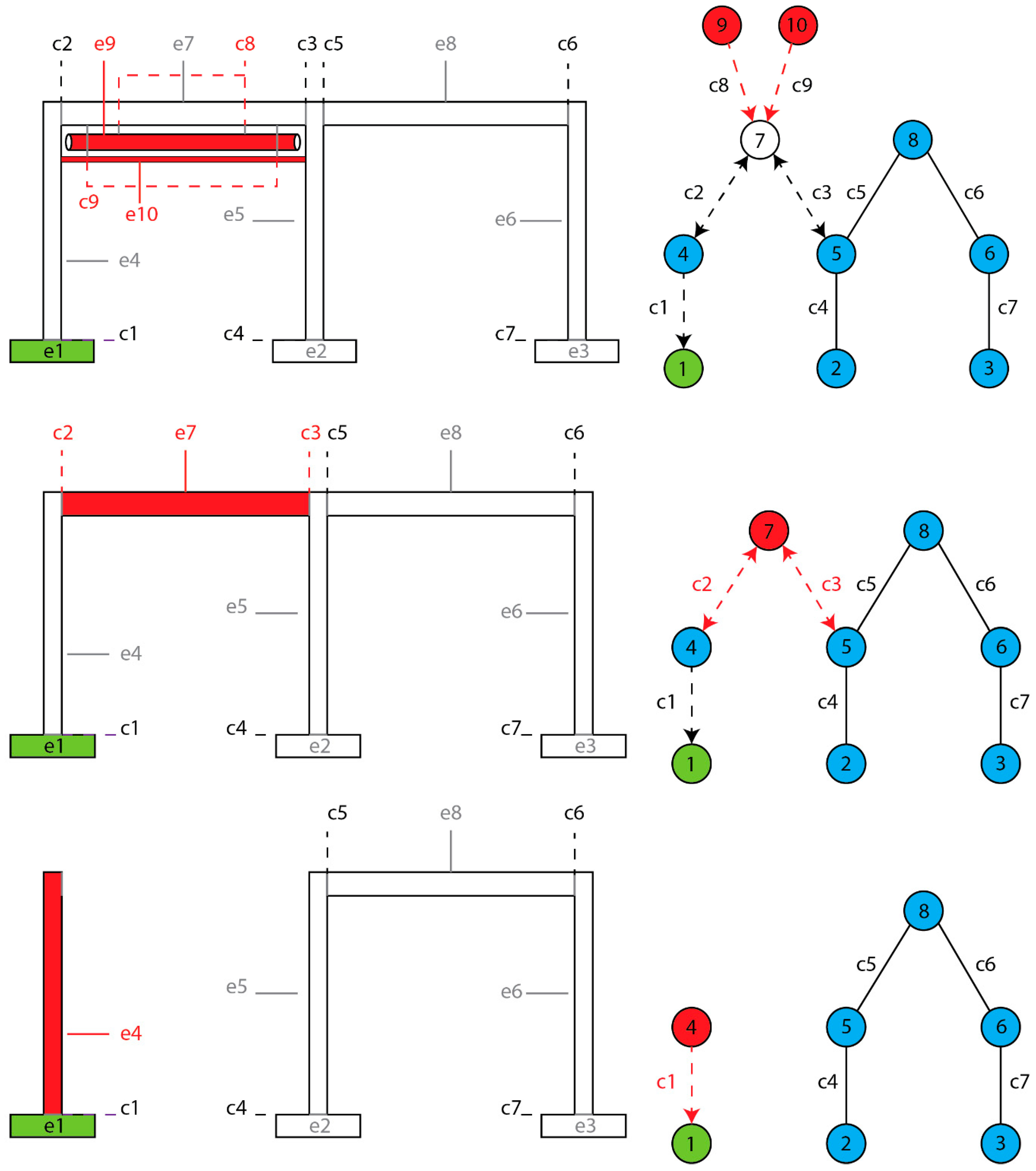
4.2.3. Propagation of Dependencies on a Path
- The propagation of dependencies seems robust and allows several cases to be distinguished quite easily.
- This case shows once again that the more information provided, the better are the results. This complies with the second guiding rule.
- Without any dependence, the answer will become “remove c1”, which is not realistic.
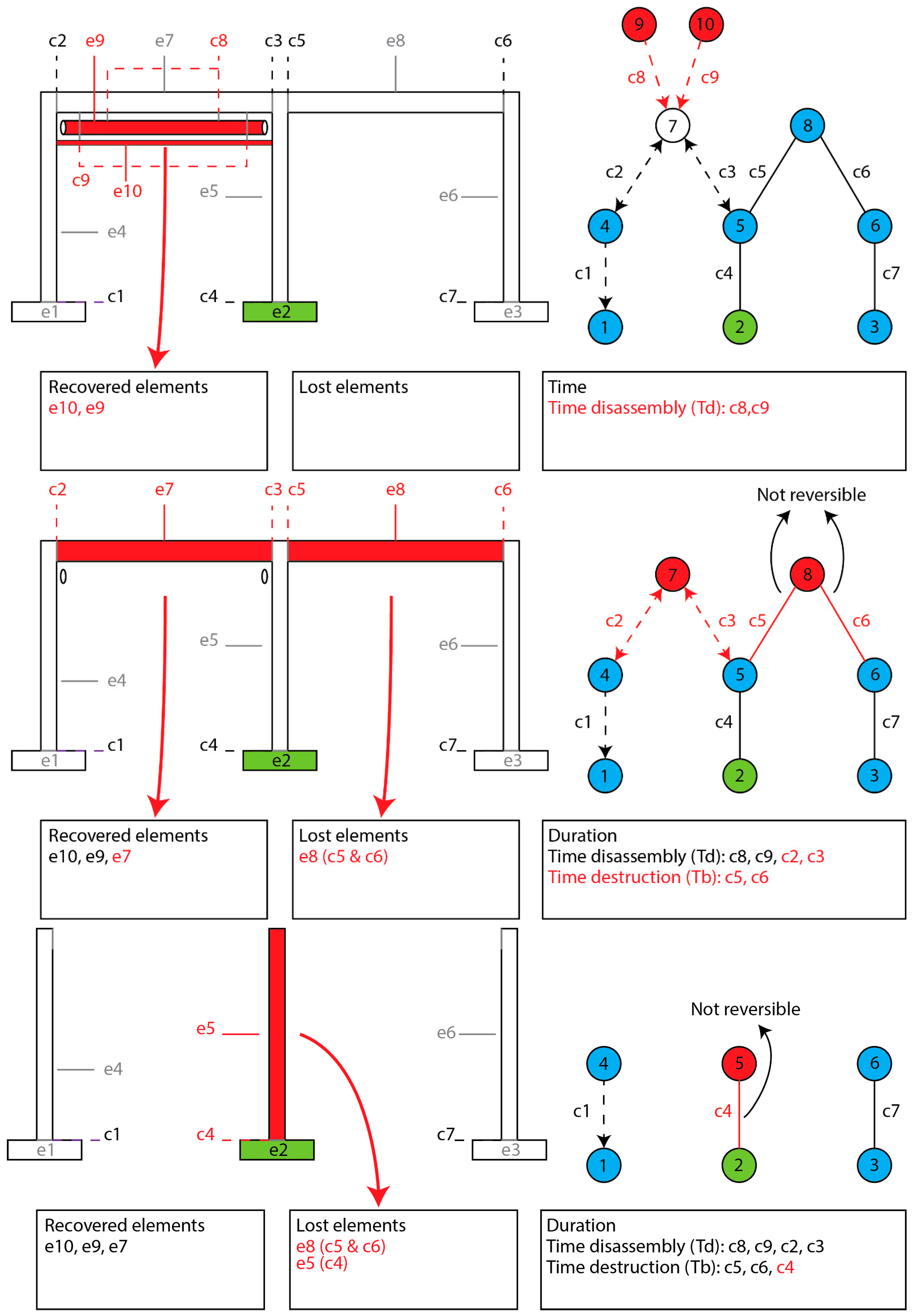
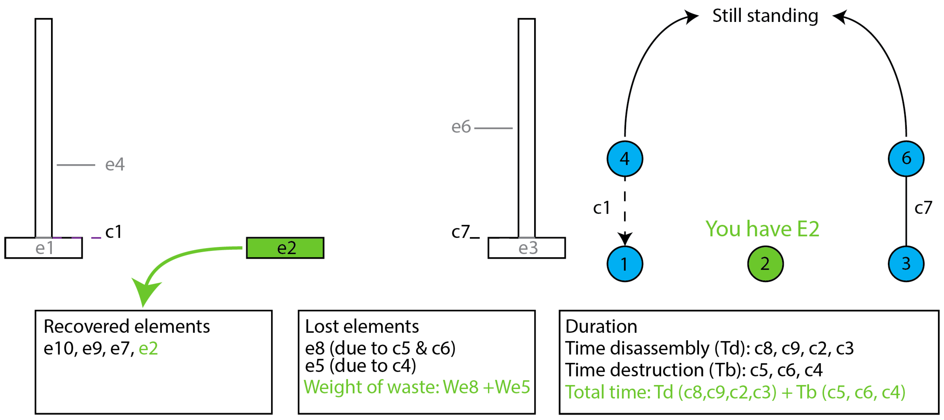
4.2.4. Complete Application of the Method on the Frame Structure
- In path P1: elements e2 and connections: nothing yet
- In path P2: elements e2, e5 and connections: c4
- The removal of connections c5 and c6 both generate the loss of element e8. Element e8 is listed twice in the lost elements list to differentiate this case with a case where only one connection is leading to the loss of e8. However, when calculating the amount of waste generated by one element, the weight will be counted only once. The time of each disconnection is considered as we do not know whether the two connections will fail together or not (to be on the safe side).
- While checking connection c4, it is important to note that although the target element is the weakest, it may still be possible to get a part of it. In the method, the elements are considered “recovered”’, only if the conditions for disassembly are met. Therefore, we have decided to overestimate waste and underestimate elements that could be recovered (to be on the safe side).
5. Discussion
5.1. Development of the Disassembly Quantification Method
5.2. Integration of Network Analysis
5.3. Integration of Building Information Modeling (BIM)
6. Conclusions
Author Contributions
Funding
Acknowledgments
Conflicts of Interest
References
- Paduart, A. Re-Design for Change: A 4 Dimensional Renovation Approach towards a Dynamic and Sustainable Building Stock. Ph.D. Thesis, Vrije Universiteit Brussel, Brussels, Belgium, 2012. [Google Scholar]
- Durmisevic, E. Transformable Building Structures. Design for Disassembly as a Way to Introduce Sustainable Engineering to Building Design & Construction. Ph.D. Thesis, Technische Universiteit Delft, Delft, The Netherlands, 2006. [Google Scholar]
- Eurostat Database. Eurostat. Available online: http://ec.europa.eu/eurostat/data/database?node_code=env_wasgen (accessed on 6 August 2018).
- Thormark, C. Recycling Potential and Design for Disassembly in Buildings. Ph.D. Thesis, Lund University, Lund, Sweden, 2001. [Google Scholar]
- Guy, B.; Ciarimboli, N. DfD—Design for Disassembly in the Built Environment: A Guide to Closed-Loop Design and Building; University Park: State College, PA, USA, 2005. [Google Scholar]
- Galle, W.; De Temmerman, N.; Allacker, K.; De Meyer, R. Geometric service life modelling and discounting, a practical method for parametrised life cycle assessment. Int. J. Life Cycle Assess. 2017, 22, 1191–1209. [Google Scholar] [CrossRef]
- Vandenbroucke, M. Design, Dimensioning and Evaluation of Demountable Building Elements. Ph.D. Thesis, Vrije Universiteit Brussel, Brussels, Belgium, 2016. [Google Scholar]
- Akinade, O.O.; Oyedele, L.O.; Bilal, M.; Ajayi, S.O.; Owolabi, H.A.; Alaka, H.A.; Bello, S.A. Waste minimisation through deconstruction: A BIM based Deconstructability Assessment Score (BIM-DAS). Resour. Conserv. Recycl. 2015, 105, 167–176. [Google Scholar] [CrossRef]
- Garber, R. BIM Design: Realising the Creative Potential of Building Information Modelling; Wiley: Chichester, UK, 2014; ISBN 978-1-118-71980-0. [Google Scholar]
- Lévy, F. BIM in Small-Scale Sustainable Design, 1st ed.; Wiley: Hoboken, NJ, USA, 2011; ISBN 978-0-470-59089-8. [Google Scholar]
- Ghyoot, M.; Devlieger, L.; Billet, L.; Warnier, A. Déconstruction et Réemploi: Comment Faire Circuler les Éléments de Construction; PPUR: Lausanne, Switzerland, 2018. [Google Scholar]
- Hansen, D.; Shneiderman, B.; Smith, M.A. Analyzing Social Media Networks with NodeXL: Insights from a Connected World; Morgan Kaufmann: Burlington, MA, USA, 2010; ISBN 978-0-12-382230-7. [Google Scholar]
- Smith, S.; Chen, W.-H. Multiple-Target Selective Disassembly Sequence Planning with Disassembly Sequence Structure Graphs. In Proceedings of the ASME 2012 International Design Engineering Technical Conferences and Computers and Information in Engineering Conference, Chicago, IL, USA, 12–15 August 2012; p. 1305. [Google Scholar]
- Teunter, R.H. Determining optimal disassembly and recovery strategies. Omega 2006, 34, 533–537. [Google Scholar] [CrossRef] [Green Version]
- Ghandi, S.; Masehian, E. Review and taxonomies of assembly and disassembly path planning problems and approaches. Comput.-Aided Des. 2015, 67–68, 58–86. [Google Scholar] [CrossRef]
- Sanchez, B.; Haas, C. A novel selective disassembly sequence planning method for adaptive reuse of buildings. J. Clean. Prod. 2018, 183, 998–1010. [Google Scholar] [CrossRef]
- Denis, F. The potential of graph theories to assess buildings’ disassembly and components’ reuse: How building information modelling (BIM) and social network analysis (SNA) metrics might help Design for Disassembly (DfD)? In Proceedings of the HISER International Conference 2017: Advances in Recycling and Management of Construction and Demolition Waste, Delft, The Netherlands, 21–23 June 2017; pp. 123–128. [Google Scholar]
- Langston, C.; Wong, F.K.W.; Hui, E.C.M.; Shen, L.-Y. Strategic assessment of building adaptive reuse opportunities in Hong Kong. Build. Environ. 2008, 43, 1709–1718. [Google Scholar] [CrossRef]
- Conejos, S.; Langston, C.; Smith, J. AdaptSTAR model: A climate-friendly strategy to promote built environment sustainability. Habitat Int. 2013, 37, 95–103. [Google Scholar] [CrossRef] [Green Version]
- Van Nunen, H. Assessment of the Sustainability of Flexible Building: The Improved Factor Method: Service Life Prediction of Buildings in The Netherlands Applied to Life Cycle Assessment. Ph.D. Thesis, Technische Universiteit Eindhoven, Eindhoven, The Netherlands, 2010. [Google Scholar]
- Gosling, J.; Sassi, P.; Naim, M.; Lark, R. Adaptable buildings: A systems approach. Sustain. Cities Soc. 2013, 7, 44–51. [Google Scholar] [CrossRef]
- Bogue, R. Design for disassembly: A critical twenty-first century discipline. Assem. Autom. 2007, 27, 285–289. [Google Scholar] [CrossRef]
- Fogg, B. A behavior model for persuasive design. In Proceedings of the 4th International Conference on Persuasive Technology, Claremont, CA, USA, 26–29 April 2009. [Google Scholar]
- Yocco, V.S. Design for the Mind: Seven Psychological Principles of Persuasive Design; Manning: Shelter Island, NY, USA, 2016; ISBN 978-1-61729-295-8. [Google Scholar]
- Fogg, B.J.; Cuellar, G.; Danielson, D. Motivating, influencing, and persuading users: An introduction to captology. In Human Computer Interaction Fundamentals; CRC Press: Boca Raton, FL, USA, 2009; pp. 109–122. [Google Scholar]


| Name | Reference Publication | Tools and Methods Used | Output Data |
|---|---|---|---|
| Durmisevic’s Knowledge Model | [2] | Fuzzy logic, disassembly sequences. | Aggregated score (disassembly and interchangeability) |
| BIM-DAS | [8] | Unweighted checklist of design strategies for deconstruction and reuse using BIM data. | Aggregated score (disassembly and reuse) |
| ARP | [18] | Multicriteria sustainability analysis tool (SINDEX). | Useful life (in years) |
| AdaptSTAR | [19] | Weighted checklist of design strategies towards adaptable buildings. | Aggregated score (various design aspects) |
| Sanchez and Haas’ SDPB method | [16] | Disassembly sequence structure graph (DSSG), automated graph plot, BIM data. | Indication of the optimized disassembly sequence path based on disassembly costs and time. |
| Criteria | Verifiers | Data Availability in BIM |
|---|---|---|
| Accessibility | The element is free to move in the disassembly direction. | Depending on the Level of Detail. |
| Transportability | Maximum weight, maximum dimensions. | Yes, if weight max is specified by the user. |
| Resistance factor [0,1] | User input or link to external database. | |
| Weight (kg) | Yes. | |
| Reversibility of connection | The two connected elements are separable without damage. | User input or link to external database. |
| Disassemble time and Demolition time | Based on empirical measurements with a weighting factor. | User input or link to external database. |
| Sequential dependence | Which other objects needs to be disassembled prior to the disassembly of object i | User input or partially automatic detection in BIM between family types (e.g., beam, column). |
| Elements | e1 | e2 | e3 | e4 | e5 |
|---|---|---|---|---|---|
| Element type | Exterior cladding | Membrane | Insulation | Masonry wall | Interior finishing |
| Transportable | Yes | Yes | Yes | No | Yes |
| Resistance | 0.7 | 0.2 | 0.4 | 1 | 0.7 |
| Weight (kg) | 10 | 2 | 5 | 150 | 5 |
| Connections | c1 | c2 | c3 | c4 |
|---|---|---|---|---|
| Reversible | Yes | No | Yes | Yes |
| Time to disconnect (s) | 60 | / | 60 | 180 |
| Time to break apart (s) | 5 | 220 | 5 | 15 |
| Elements to Recover | e1 | e2 | e3 | e4 | e5 |
|---|---|---|---|---|---|
| 1. Is element transportable? | Yes | Yes | Yes | No, quick check failed. | Yes |
| 2. Are all its connections reversible? | Yes, quick check succeeded. | No, check resistances. | No, check resistances. | / | Yes, quick check succeeded. |
| 3. Is element the most resistant? | / | No, quick check failed. | Yes, quick check succeeded. | / | / |
| Conclusion | Continue the assessment | Cannot be recovered | Continue the assessment | Cannot be recovered | Continue the assessment |
| Strengths | Weaknesses | Opportunities | Treats |
|---|---|---|---|
| Quantitative assessment | “Elements” not yet completely defined | Basis for a software tool | Can become too complicated |
| Linked to design aspects | Missing verifiers | Several methods’ “subparts” already exist as algorithms | Can be too simplistic |
| Transparent method | / | / | / |
| Using available BIM data | / | / | / |
© 2018 by the authors. Licensee MDPI, Basel, Switzerland. This article is an open access article distributed under the terms and conditions of the Creative Commons Attribution (CC BY) license (http://creativecommons.org/licenses/by/4.0/).
Share and Cite
Denis, F.; Vandervaeren, C.; De Temmerman, N. Using Network Analysis and BIM to Quantify the Impact of Design for Disassembly. Buildings 2018, 8, 113. https://doi.org/10.3390/buildings8080113
Denis F, Vandervaeren C, De Temmerman N. Using Network Analysis and BIM to Quantify the Impact of Design for Disassembly. Buildings. 2018; 8(8):113. https://doi.org/10.3390/buildings8080113
Chicago/Turabian StyleDenis, François, Camille Vandervaeren, and Niels De Temmerman. 2018. "Using Network Analysis and BIM to Quantify the Impact of Design for Disassembly" Buildings 8, no. 8: 113. https://doi.org/10.3390/buildings8080113
APA StyleDenis, F., Vandervaeren, C., & De Temmerman, N. (2018). Using Network Analysis and BIM to Quantify the Impact of Design for Disassembly. Buildings, 8(8), 113. https://doi.org/10.3390/buildings8080113