Article

Seismic Vulnerability for RC Infilled Frames: Simplified Evaluation for As-Built and Retrofitted Building Typologies

Department of Structures for Engineering and Architecture, University of Naples Federico II, 80125 Naples‎, Italy
*
Author to whom correspondence should be addressed.
Buildings 2018, 8(10), 137; https://doi.org/10.3390/buildings8100137
Submission received: 7 August 2018 / Revised: 21 September 2018 / Accepted: 26 September 2018 / Published: 28 September 2018

Abstract

:
Several studies investigated the influence of infills on the response of reinforced concrete (RC) frames. However, possible shear brittle failures are generally neglected. The interaction between the infill panels and the surrounding frames can lead to anticipated brittle-type failures that should be considered in code-based assessment of lateral seismic capacity. This paper investigates, by means of simplified pushover analyses, on the effect of infills on the lateral seismic capacity explicitly considering possible brittle failures in unconfined beam-column joints or in columns. Archetype buildings representative of existing gravity load designed (GLD) RC frames of three different height ranges are obtained with a simulated design process and a sensitivity analysis is performed to investigate on the effect of infill consistency on the capacity. Moreover, possible alternative local retrofit interventions devoted to avoiding brittle failures are considered, evaluating their relative efficacy in case of different infill typologies. It is seen that for the considered existing GLD buildings, the attainment of life safety limit state is premature and happens before the damage limitation limit state. The capacity can be increased with application of local retrofit interventions. However, the retrofit efficacy varies depending on the infills consistency if the horizontal action transferred from the infills to the surrounding frame is not absorbed by the retrofit solution.

1. Introduction

Seismic vulnerability of buildings represents the susceptibility of buildings to be damaged by earthquakes of given intensity. Depending on the scope of the vulnerability analysis, different levels of damage may be considered. Generally, with reference to civil protection purposes, the damage scale is defined by a qualitative description of the damage on structural and nonstructural elements, also considering the damage severity and extent, and refers to an estimation for the entire building. The reference damage scale in Europe is that defined in the European macro-seismic scale EMS98 [1], while indications for United States may be found in [2]. On the other hand, vulnerability studies may be used also with the purpose of evaluating the building seismic capacity corresponding to the attainment of code-based limit states, evidencing possible weaknesses in selected building typologies. In such a case, the damage scale is graduated with reference to selected relevant limit states and often deformation limits at a storey, or the crisis of a single element drives the “failure” of the entire building. The adoption of code-based limits for damage graduation is useful for estimating the possible overpassing of selected limit states relevant for the codes (e.g., damage limitation limit state or life safety limit state), the eventual need to retrofit or the effect of selected mitigation interventions to reduce earthquake damage [3].
This paper performs a vulnerability study on reinforced concrete (RC) infilled frame buildings, representative of existing gravity load designed typologies in Italy.
Infill panels are usually treated as non-structural elements, considering their effect as substantially beneficial with respect to building’s seismic behavior [4]. In fact, in the case of uniformly infilled structures, with infill panels having adequate consistency, the buildings are generally less vulnerable with respect to equivalent bare structures [5]. However, the seismic behavior of the frame-infills assemblage is strongly influenced by a number of factors concerning infills strength and distribution: if the infills are not present or weakened due to the presence of large openings at one storey there is a high probability of soft storey effects; this circumstance may occur also for uniformly distributed infills, when they are weak and relatively brittle and/or for high seismic demand with respect to the system resistance [6,7]. Moreover, if the infill contribution in terms of strength and stiffness is not adequately proportioned with respect to the RC frame, the triggering of a number of local effects may affect the formation of a global-type mechanism, leading, instead, to a premature collapse of the columns at a single storey [8]. This is even more probable in case of non-conforming elements with inadequate reinforcement detailing, where local interaction between infills and RC columns may cause structural collapse due to shear failure of the columns or due to a shear friction failure.
Strength and stiffness characteristics of the infill panels, and more generally of the infill-frame assemblage, are strongly dependent on a number of factors such as compressive strength, shear (cracking) resistance, longitudinal and transversal elastic modulus of the masonry panels, the quality of connection between the panels and the surrounding frame, the openings, workmanship ability, etc. [9,10]. For what concerns the mechanical properties, although they may be associated to the characteristics of the natural/artificial masonry elements and of the mortar forming the panel, and on the disposition of the elements (vertical or horizontal rows, overlapping etc.), it is still observed a high variability of these properties, with coefficients of variation that may be major than 40% [11].
Several studies attempted to evaluate the influence of infills in the linear or nonlinear response of RC frames. For example, in [12] a parametric investigation on the effect of the infill wall area on the global elastic drift ratios of RC frames is performed, in [13,14] the variation of elastic drift ratios considering infills distribution and opening percentage is studied, while in [15] a probabilistic analysis considering the effect of uncertainties of the infills elastic modulus and of the equivalent strut’s effective width on the building elastic response is presented. However, the presence of infills may alter the RC structural response also in the non-linear stage, e.g., by modification of the type of collapse mechanism [16]. In [17] the seismic reliability on infilled RC frames is studied by means of non-linear dynamic analyses of representative frames, in [18] is evaluated the sensitivity of the seismic response parameters to the uncertain modelling variables of the infills and frame by means of pushover analyses and in [19] a parametric investigation on the results of pushover analyses to evaluate the influence of the mechanical and geometrical properties of masonry infills on the whole structural response is performed. However, these studies do not consider possible brittle failures in unconfined lateral joints or in columns with inadequate transversal reinforcement. The interaction between the infill panels and the surrounding frames can lead to anticipated brittle-type failures that should be considered in code-based assessment of lateral seismic capacity. Additionally, when designing possible local retrofit interventions on nonconforming elements, the effect of the aggravating lateral solicitations transmitted from the infill panel to the RC elements should be properly considered.
This paper investigates on the effect of infills on the lateral seismic capacity considering possible brittle failures in unconfined lateral joints or in columns, which are a common cause of collapse for existing RC buildings not designed for seismic loads or with obsolete seismic provisions. Archetype buildings representative of existing gravity load designed RC frames of three different height ranges are obtained with a simulated design process and a sensitivity analysis is performed to investigate on the effect of infill consistency on the capacity. Moreover, possible alternative local retrofit interventions devoted to avoiding brittle failures are considered, evaluating their relative efficacy in case of weak or stronger infills. Building response is studied performing simplified nonlinear static pushover analyses and evaluating the lateral seismic capacity at code-based damage limitation SLD and life-safety SLV limit states [20,21]. Frame-infill interaction is evaluated by suitable post-processing of pushover results allowing the evaluation of lateral displacement corresponding to the attainment of seismic capacity.

2. Analytical Based Assessment of the Seismic Capacity

The lateral seismic capacity is evaluated by means of nonlinear static pushover, identifying on the pushover curve the points corresponding to the attainment of two limit states, namely damage limitation limit state SLD and life safety limit state SLV. Then, the capacity is expressed in terms of the maximum peak ground acceleration PGAc that the building is able to withstand for each limit state (PGAc,SLD and PGAc,SLV). A capacity spectrum method approach is employed for transformation of the capacity curve relative to the multi-degree of freedom model MDOF representative of the real building to the corresponding equivalent single degree of freedom SDOF system and for evaluation of the capacity with a spectral approach [22].

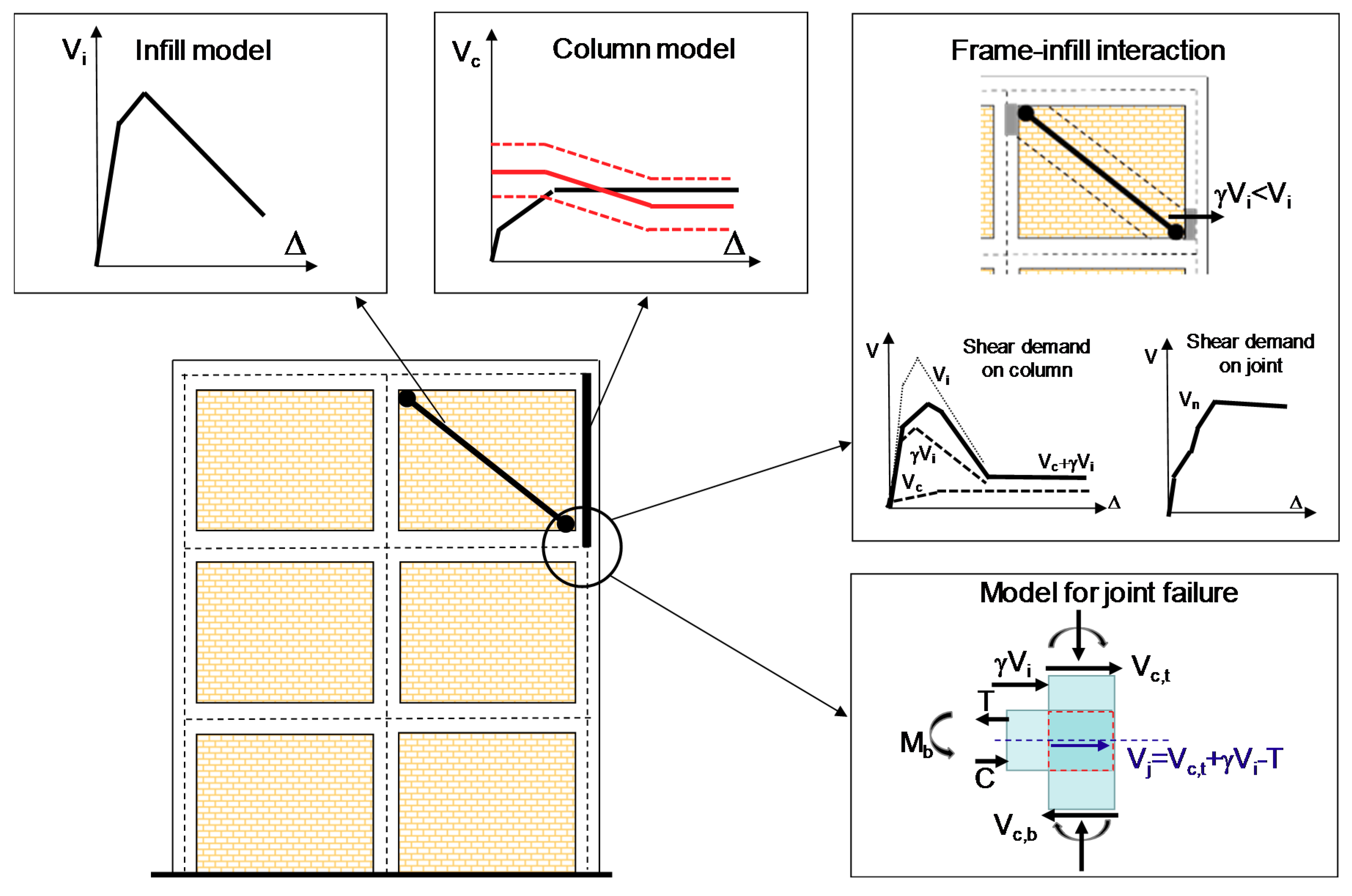
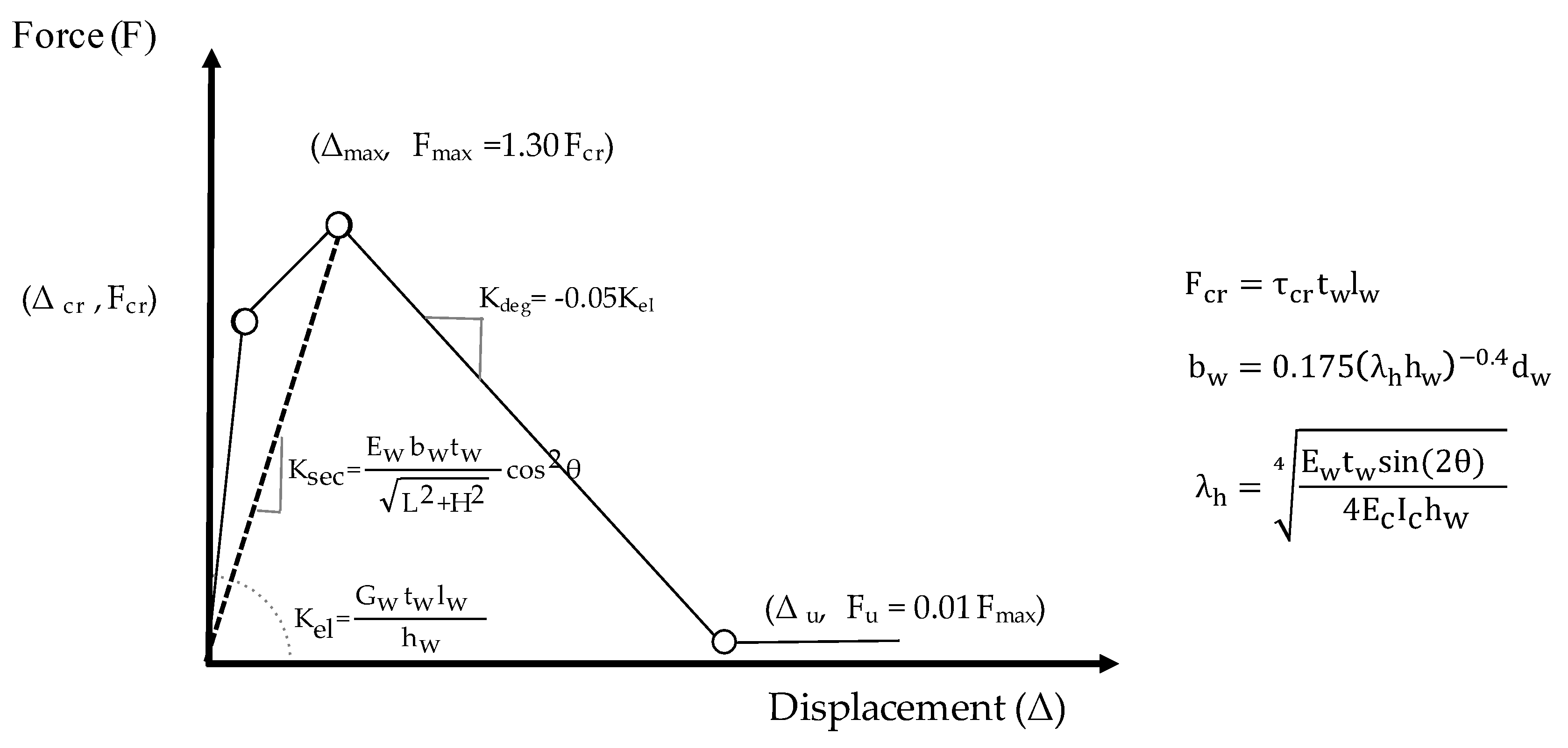
2.1. Nonlinear Building Modeling

The structural model for the generic archetype building is obtained with a simulated design approach as already described in [23] and further simplified in [24]. In this paper, we consider only gravity load designed (GLD) regular buildings of rectangular shape. In particular, complying with the building codes (e.g., [25,26] and following modifications or integrations) and design practice in force at the time of construction (e.g., [27]), the structural elements are firstly dimensioned; for this application we consider GLD buildings constructed in Italy between 1950 and 1980. The longitudinal reinforcement in columns is designed with reference to minimum longitudinal reinforcement geometric ratio prescribed by code for gravity load designed buildings, while for the beams longitudinal reinforcement is designed considering envelope moments deriving by limit load combination schemes according to construction practice. Note that in the typical structural configuration of gravity load designed buildings, the horizontal slabs are one-way slabs. Hence, the deep beams mainly deputed to absorb gravity loads are just in the direction perpendicular to the one-way slabs. This implies that generally the RC frames formed by columns and deep beams are only in one direction, while in the other direction the frames are formed by columns and beams that are embedded in the thickness of the horizontal slab; only the perimeter frames are always with deep beams [27]. More details for the simulated design process can be found in [23]. The possible presence of infills is also considered. The perimeter frames are infilled, and it is supposed that the area of openings for the infills correspond to 20% of the infill area for each panel.
Thanks to symmetry, each building is analyzed separately in both the longitudinal (X) and the transversal (Y) directions, simply assembling the contribution of the relevant frames as acting in parallel. The nonlinear model includes the effect of the infills, which are modeled as equivalent single strut acting only in compression. Global model is assembled considering that ends of the columns are restrained against rotation (Shear Type model), as already proposed in [28]. This simplifying hypothesis was already introduced in other studies for the evaluation of RC infilled frames [29]; it allows the analyses to reproduce the seismic response of existing buildings with a reasonable degree of approximation and at the same time to reduce the computational effort, which is a crucial aspect when large scale analyses have to be performed. This way, the lateral response of the structure under a given distribution of lateral forces can be determined based on the interstorey shear–displacement relationships at each storey.
Figure 1 shows a schematic representation of the generic frame of the building with identification of the columns and infill panels and the nonlinear model adopted for each of these elements. For RC columns, a tri-linear moment-rotation envelope is built with cracking and yielding as characteristic points (Figure 2). Moment at yielding (My) is calculated according to the simplified formulation proposed by Biskinis and Fardis [30], while the rotation at yielding (θy) is identified by My and the secant stiffness (EIy) provided by Haselton et al. [31]. The total shear demand acting on the column (black continous line in Figure 2b) is evaluated by transforming the moment-rotation (M-θ) relationship into the corresponding shear-displacement (V-Δ) curve (dashed gray) and summing the effect of infill-induced shear stress (dotted gray). Then, for the non-ductile RC building, the possible shear failure of columns is identified by comparing the obtained column shear demand with the column shear capacity (red continuous line) evaluated as described in Section 2.2. The column shear capacity can be improved by retrofitting the building through the application of external fiber reinforced polymers FRP layers as described in Section 2.4. Figure 2b shows the increased shear capacity when applying one (dashed red) or two (dotted red) FRP plies as a retrofit option. Note that, for the selected column, two FRP plies may avoid column brittle failure.
The behavior of infill panels can be simulated adopting either micro or macro-modelling techniques [32]. The latter are frequently adopted due to their simplicity and efficiency into the description of the global response of masonry infilled RC frames. In particular, the single-strut modeling approach is widely adopted to simulate the behavior of global effects of infills on frames. Several models were proposed for the determination of the force-displacement relationship of the equivalent single strut masonry infills (e.g., [32,33]). In this study, the force-displacement envelope of the equivalent diagonal struts is evaluated according to the model proposed by Panagiotakos and Fardis [33], see Figure 3. In this model, the four branches lateral force-displacement relationship is constructed depending on the geometry of the surrounding frame, and on both mechanical and geometrical characteristics of the infill masonry [34].
The geometry of the infill panel is introduced in terms of gross length and height, L and H, clear length and height, lw and hw, clear diagonal length, dw, and in terms of inclination of the diagonal strut θ = arctan(hw/lw) with respect to the horizontal plane. The mechanical characteristics of the masonry are expressed in terms of elastic shear modulus, Gw, Young’s modulus, Ew, and shear cracking strength, τcr. Finally, the equivalent strut width, bw, is determined according to Mainstone’s formula [35] depending on quantities reported above and on the moment of inertia, Ic, and Young’s modulus, Ec, of columns. When openings are present in the infill panel, e.g., to accommodate windows or balconies, both the stiffness and the strength of the infill panel are reduced. Several studies investigated the influence of shape, size and location of openings on the seismic performance of infilled frames (e.g., [36,37]). In this study the presence of the opening is considered introducing a reduction factor λ0 = max(0; 1–1.8 Ao/Ap) [38] that modifies both the stiffness and the strength of the infill panel, where Ao is the area of openings and Ap the area of infill panels.
Once that force-displacement/moment-rotation relationships is defined for each relevant member, these are transformed in the corresponding shear-displacement curves and then, considering the RC frames and infill elements at the same storey as acting in parallel, a multi-linear interstorey shear-displacement relationship is constructed for each storey. Assuming a given lateral force distribution shape, e.g., proportional to first mode shape or with forces proportional to storey masses, the global pushover curve is finally obtained in closed-form through a force-controlled procedure up to the peak response. After the peak, a displacement-controlled procedure is followed, as suggested in [28]. In particular, the storey in which the maximum ratio between interstorey shear demand and strength occurs is the only one to reach its peak interstorey shear resistance and to experience softening post-peak behavior. In this storey, the interstorey displacement continuously increases, while the displacement in remaining storey will decrease following an unloading branch with a stiffness value equal to the elastic one.

2.2. Limit States for Non-Ductile RC Buildings

Two relevant code-based limit states, namely damage limitation (SLD) and life safety limit state (SLV), are detected along the pushover curves to represent lateral seismic capacity of the building.
Concerning SLD, modern codes such as EC8–part 1 [20] and the Italian code [21], prescribe that maximum interstorey drift IDRmax should not exceed the value of 5‰ for buildings having brittle non-structural components connected to the structure, e.g., in case of brick masonry. If the contribution of infill panels is explicitly considered in the model the threshold for IDRmax should be reduced [39], and a value that refers to ordinary masonry, i.e., 2‰, should be adopted.
Adopting a code-based collapse criterion, SLV is evaluated as a function of the ultimate capacity of primary components (first element to reach its displacement or strength capacity in the whole structure). For RC columns, ductile failure allows to exploit the ultimate rotation capacity of the elements. However, the displacement capacity of existing members is often limited by lack of proper reinforcing details. Indeed, in existing buildings designed prior to the introduction of seismic-oriented design codes, structural capacity could be significantly limited due to structural deficiencies such as inadequate detailing of reinforcement (e.g., light transvers reinforcement in columns and no transverse reinforcement in the beam-column joint), deficiencies in anchorage, smooth rebars, and the absence of any capacity design principles [40,41]. Thus, to properly assess the lateral capacity of existing buildings, possible brittle failures due to reduced shear capacity for the columns or in unconfined lateral joints have to suitably identified. Suitable identification of the rotation corresponding to the attainment of flexural or shear capacity allows to define the type of failure for the element. In particular, the rotation at SLV limit state θSLV is defined with a procedure that is based on the comparison between the yielding shear (Vy), calculated as the ratio between My and the shear span of the column (Lv), and the shear strength (Vn) calculated according to [42]. Lv is assumed equal to half of the column height, consistently with the shear type assumption. Depending on the ratio Vy/Vn, three possible failure modes are expected: flexure, flexure-shear or pure shear failure. If Vy/Vn < 1 for any value of ductility demand, RC column is expected to fail in flexure and θSLV corresponds to ¾ of the ultimate chord rotation for ductile members [39]. If Vy/Vn ≥ 1, the column is expected to fail in shear or flexure-shear and θSLV is evaluated correspondingly to the intersection point between column shear demand and column shear capacity (see Figure 2b).
Beam-column joints of existing GLD buildings typically have no transverse reinforcement in the joint region. Due to lack of shear reinforcement, the shear strength of the joint panel zone is only provided by concrete resistance and can be directly related to the principal tensile strength of the concrete. In this case, using the Mohr’s circle for state of stress, the shear strength of joints can be related to principle tensile strength of concrete and to column axial load as follows:
V jt = A j σ nt , lim 2 + σ nt , lim N i A j  
where Vjt is the joint tensile strength, σnt,lim is the principal tensile strength, N is the column axial load in the upper column and Aj is the joint cross-sectional area.
In the same way, beam-column joints may potentially fail in shear due to high principal compression stresses. Such failures can be quantified using the principal compression strength instead of the principal tension strength as follows:
V jc = A j σ nc , lim 2 σ nc , lim N i A j  
where Vjc is the joint compressive strength and σct,lim is the principal compressive strength.
According to the Italian seismic code [39], the brittle failure of unconfined joints is attained for a limit value of the tensile principal stress of σ nt , lim = 0.3 f c or for a compressive principal stress of σ nc , lim = 0.5 f c , with fc expressed in MPa. Adopting the simplified free-body diagram for an external beam-column joint depicted in Figure 1 (lower-right panel), the shear force demand acting at the core of the joint (Vj) can be calculated as Vj = Vc,t − T, where Vc,t is the shear demand of the upper column (subscript t stands for top) and T represents the tension force developing in the steel reinforcement of the beam. It is assumed that T = Mb/(0.9∙d), where Mb is the beam moment and d is the effective depth of beam cross-section (0.9∙d is the internal lever arm). The maximum value of T is limited by yielding strength of longitudinal reinforcement, thus T ≤ As∙fy, where As is the area of the beam top reinforcement, and fy is the yield strength of reinforcing steel. Beam moment, Mb, is calculated based on equilibrium considerations, assuming that the inflection point is located at the mid-height of the columns. In particular, Mb = Vc,t∙Lv,a + Vc,b∙Lv,b where Lv indicates the shear span, subscript a and b indicates the member above and below the considered joint, respectively; and subscript c indicates the column.
The presence of masonry infills can provide a significant contribution to the global response framed structures under seismic loads, increasing both stiffness and lateral strength of RC structures. On the other hand, the presence of infills induces additional shear forces at the ends of beams and columns that may lead to the activation of brittle collapse mechanisms especially in non-ductile RC structures (e.g., Figure 4). The quantification of these additional shear forces was addressed by different authors [43,44] and was found to be depending on both geometrical and mechanical characteristics of the panel. In this work, according to [44] it is assumed that the additional shear force induced in the surrounding columns is equal approximately to the 25% of the horizontal component of axial load experienced by the equivalent strut. Considering this additional shear force acting on the node, the previous formulation is modified in Vj = Vc,t + γVi − T, where Vi is the shear force acting in the masonry infill panel and γ is a reduction coefficient that accounts for the proportion of the force that is transferred from the infill to the column (here assumed as γ = 0.25). Note that in corner columns it often happens that the absolute value of T significantly exceeds the absolute value of Vc,t; hence, if the effect of the infills is neglected it generally happens that a higher value of Vj is obtained, that is a conservative assumption. On the other hand, due to the additional shear force γVi on the column, column shear failure may occur at lower drifts with respect to the case where the infill action is neglected.

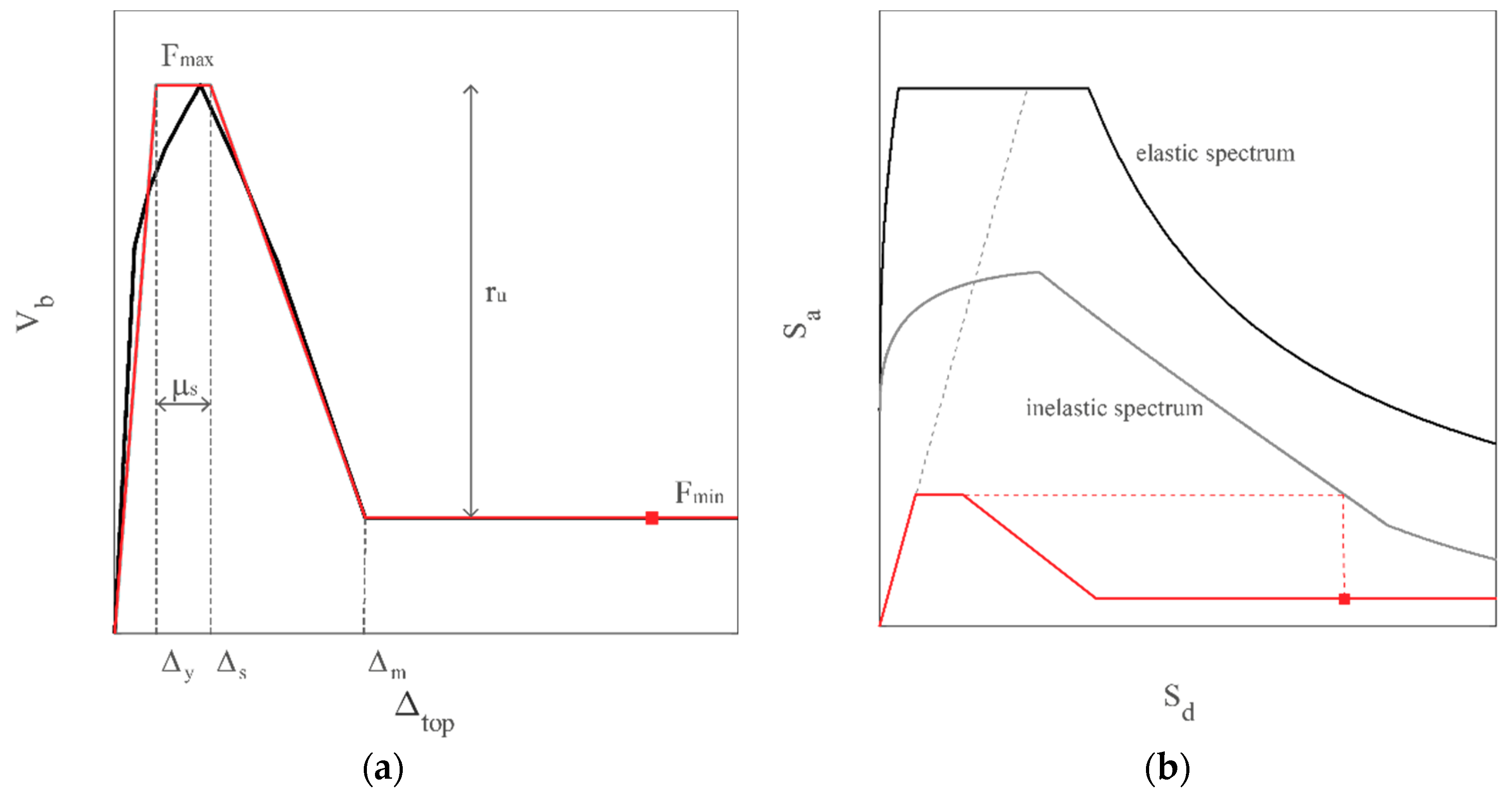
2.3. Seismic Capacity

The seismic capacity, corresponding to the attainment of maximum interstorey drift equal to 2‰ for SLD limit state and to brittle or ductile failure of an RC element for SLV limit state, is detected along the pushover curve. In order to evaluate the building behavior with respect to code prescriptions it is useful to express the capacity in terms of maximum peak ground acceleration PGAc that the building is able to withstand for each limit state (PGAc,SLD and PGAc,SLV). Indeed, the ratio of PGAc versus the seismic demand expressed by the design peak ground acceleration at the relevant limit state PGAd, represent the building safety index IS. The building safety index is a widely used parameter to evaluate the performance of a construction with respect to new building standards [45,46,47,48].
Starting from the pushover curve, the evaluation of inelastic spectral displacement corresponding to the seismic capacity, and the corresponding PGAc, can be performed via the capacity spectrum method (CSM) in the modified version proposed in [49,50] for infilled frames.
Following the approach suggested in [50] the pushover curve can be approximated with a quadri-linear curve adopting an equivalent energy principle. In particular, essential parameters describing the quadrilinear are the maximum and minimum strength, Fmax and Fmin, the displacement corresponding to the yielding of the equivalent system Dy and the initial and final points of the softening tract Ds and Dm, as shown in Figure 5a. Those data, together with the seismic mass mi at the generic ith storey and the normalized deformed shape Φ, allow determining the transformation factor Γ and the equivalent single degree of freedom SDOF system, defined by the mass m* = ΣmiΦi, the maximum strength Cbmax and the period T*:
C bmax = F max Γ m g
T = 2 π m D y F max
Two possible shape of vector Φ, representing normalized deformed shape, are assumed, the former proportional to first mode shape and latter proportional to inertia forces induced by constant acceleration along the height—the so-called mass proportional load.
The pushover expressed in terms of the displacement of the equivalent SDOF Δ* = Γ·Δtop and Cb is the so-called capacity curve, that can be used to represent the behavior of a SDOF system in a spectral approach, i.e., in the acceleration displacement response spectrum ADRS format. Starting from the defined quadri-linear curve some of the parameters to determine the seismic demand with a spectral approach may be derived. Adopting the R-μ-T relationship introduced in [49] for infilled buildings, in fact, in addition to the elastic period T*, it is necessary to determine also a strength factor ru, defined as the ratio of minimum strength Fmin versus maximum one Fmax, and the ductility μs at the beginning of the softening branch, given by the ratio of Δs versus Δy.
Hence, given the input elastic spectrum, the elastic demand in terms of displacement and acceleration (Sde, Sae) is determined in correspondence of the elastic period T* of the SDOF equivalent system; the reduction factor Rμ corresponds to Sae/Cbmax. The ductility demand μ is evaluated starting from the R-μ-T relationship introduced in [49]; finally, the inelastic displacement demand Sdi is obtained multiplying the μ for the displacement at the elastic limit Δ*y of the equivalent SDOF. Figure 5b illustrates the application of the CSM for an infilled building. By scaling the elastic spectrum, the corresponding inelastic spectrum is also scaled, and it is possible to find the elastic spectrum such that the inelastic displacement demand corresponds to the spectral seismic capacity of the building. The corresponding anchoring peak ground acceleration is PGAc.
In this paper Eurocode 8 spectral shape [20] for a subsoil B category is adopted for exemplification purposes, but other spectral shapes could be equally used.

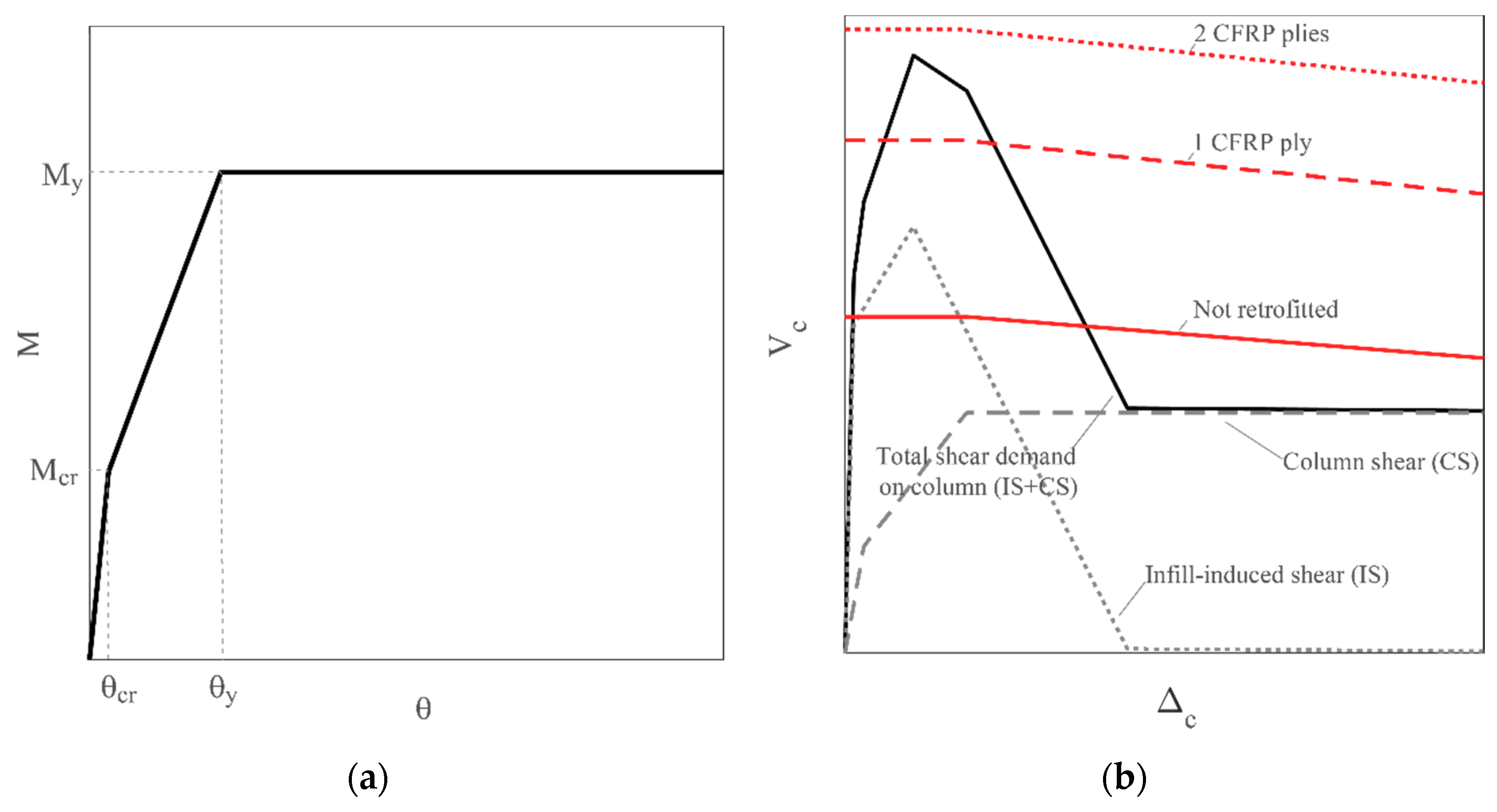
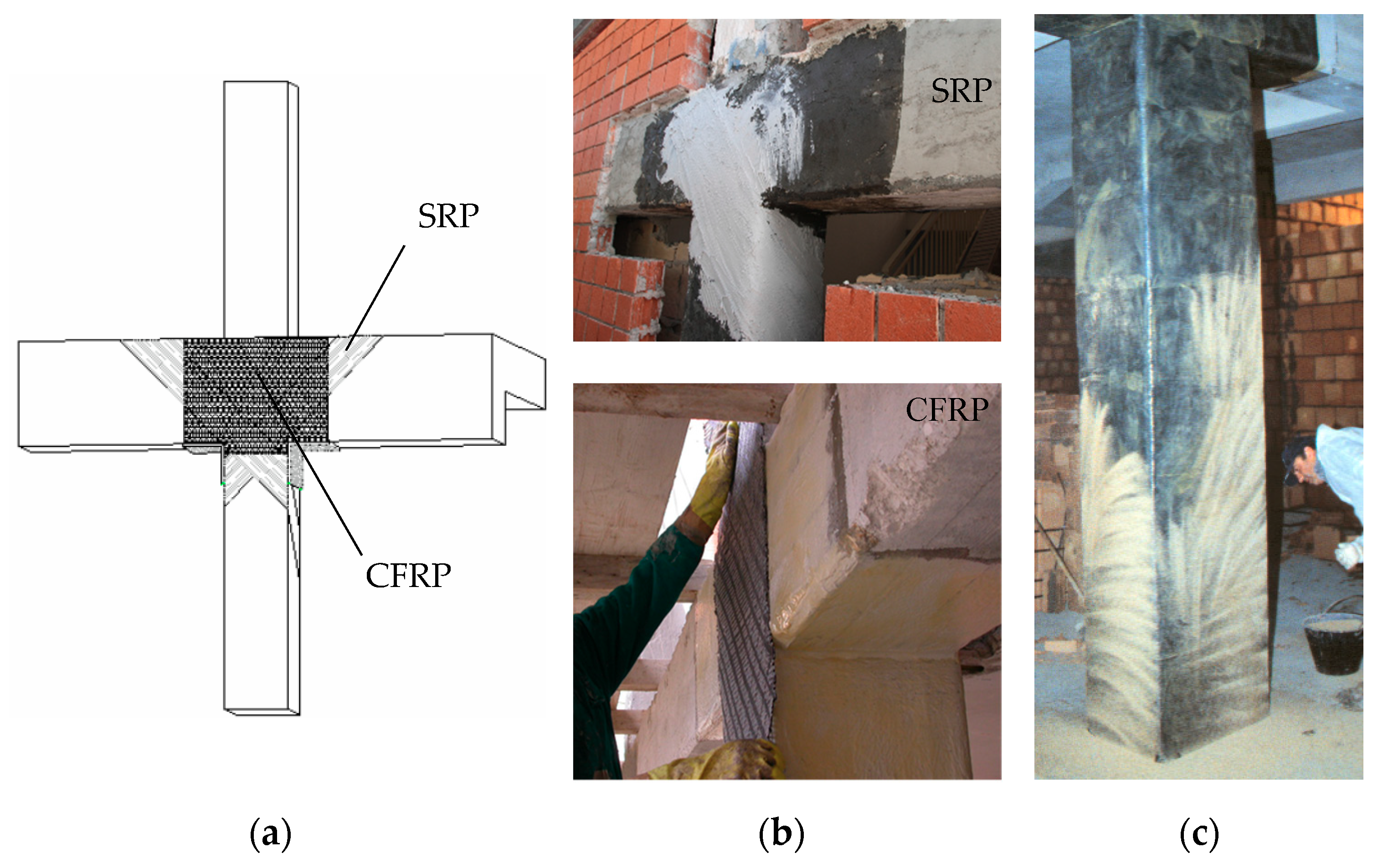
2.4. Local Retrofit of Joints and Columns with FRP Wrapping

Different strategies can be adopted to enhance the structural performances of existing buildings. The structural capacity may be increased in terms of ductility, stiffness or strength or by reducing the seismic demand adopting many local or global strategies [21,51,52]. Among possible techniques, an effective strategy for existing RC structures could be based on local modification of components that are inadequate in terms of strength or deformation capacity. It aims at increasing the strength or deformation capacity of deficient components to significantly increase the structural seismic capacity even under limited budget constraint. This local strengthening technique has the advantage to require only the assessment of local components capacity increase, without the need to perform a new global analysis of building response, provided that global mass and structural stiffness are not significantly affected by the local strengthening intervention. In this paper, with the aim of investigating the effect of widely used retrofit solutions, the strategy employing externally bonded FRP reinforcement is applied for building upgrading. In particular, the FRP strengthening on corner beam–column joints and the increase of the shear strength of columns with full-height FRP reinforcement are considered. Confinement by FRP of columns and joints results in an increase of the building deformation capacity avoiding brittle failure modes [53].
For what concerns the joint strengthening, the model proposed in [54] is adopted. In such a model it is supposed that the FRP system contributes to the principle tensile stress with a component that depends on the inclination of the fibers, and that the FRP fibers provide a similar contribution as the internal steel reinforcement. To evaluate the global strengthening effect on the corner joints, it is supposed to apply quadriaxial carbon fiber reinforced polymers CFRP fabric with fibers inclined of 0°, ±45°, and 90° at the beam axes. One or more layers of CFRP can be applied, depending on the strength increase to realize. In order to prevent shear failure at the column joint interface due to local effects of infills, steel reinforced polymer SRP composites in the form of uniaxial systems are disposed around the beam column–joint prior to application of CFRP quadriaxial fabric (Figure 6a,b) [55].
The increase of columns shear strength can be obtained with external FRP reinforcement, strengthening the columns with discontinuous or continuous uniaxial CFRP strips, with fibers perpendicular to the column longitudinal axis (see e.g., Figure 6c). Depending on the strength increase to realize, one or more plies of CFRP can be applied. To evaluate the shear capacity of RC columns strengthened with FRP, the FRP contribution can be added to the original capacity of the member, as suggested by international codes provisions [56,57]. The obtained strength increase can be easily taken into account for assessment of the SLV limit state in retrofitted structures [58].

3. Example Application for RC Infilled Building Typologies

Adopting the methodology described in Section 2, the model for three archetype regular buildings of rectangular shape, representative of existing GLD RC frames of 3, 5, and 7 storeys are obtained with simulated design. The structural model for each archetype building is fixed, with bay lengths in longitudinal and transversal direction assumed to be ax = ay = 4.3 m and interstorey height az = 3 m (see Figure 7). For the three-storey buildings, transversal frame columns dimensions at the first storey are 30 × 30 cm with column reinforcement is 4ϕ12 for each column. For the five-storey buildings, transversal frame columns dimensions at the first storey are 30 × 30 cm for corner columns and 30 × 40 for interior columns; longitudinal reinforcement consists of 4ϕ12 for corner columns and of 6ϕ12 for interior columns. For the seven-storey buildings, transversal frame columns dimensions at the first storey are the same that for the five-storey buildings while the longitudinal reinforcement consists of 6ϕ12 for corner columns and of 8ϕ12 for interior columns. Referring to the concrete and steel properties, a compressive concrete stress fc = 25 MPa and a steel tensile yielding stress fy = 399 MPa are chosen as representative values for GLD buildings constructed in the decade ’62–’71.
The infills consistency is assumed to be variable depending on the infill thickness and strength. In particular, we assume that weak (W) and medium (M) panels are realized with a double layer brick infill having (80 + 80) mm or (120 + 120) mm thickness, respectively (global thickness tw = 160 mm for W and tw = 240 mm for M), while a single layer brick infill of (300) mm thickness is assumed for strong (S) panels; these infill masonry configurations are widely used in European building practice [59]. Concerning the elastic shear modulus, it is assumed a mean value Gw = 1089 MPa for W and M infills and Gw = 1296 MPa for S ones. These values are chosen according to the proposal of [59] and are deemed to represent increasing infills stiffness. The Ew is assumed equal to 10/3 Gw coherently to the ratio that can be inferred from [26], while cracking strength of the masonry is considered linearly dependent on Gw according to boundary values indicated in [26].

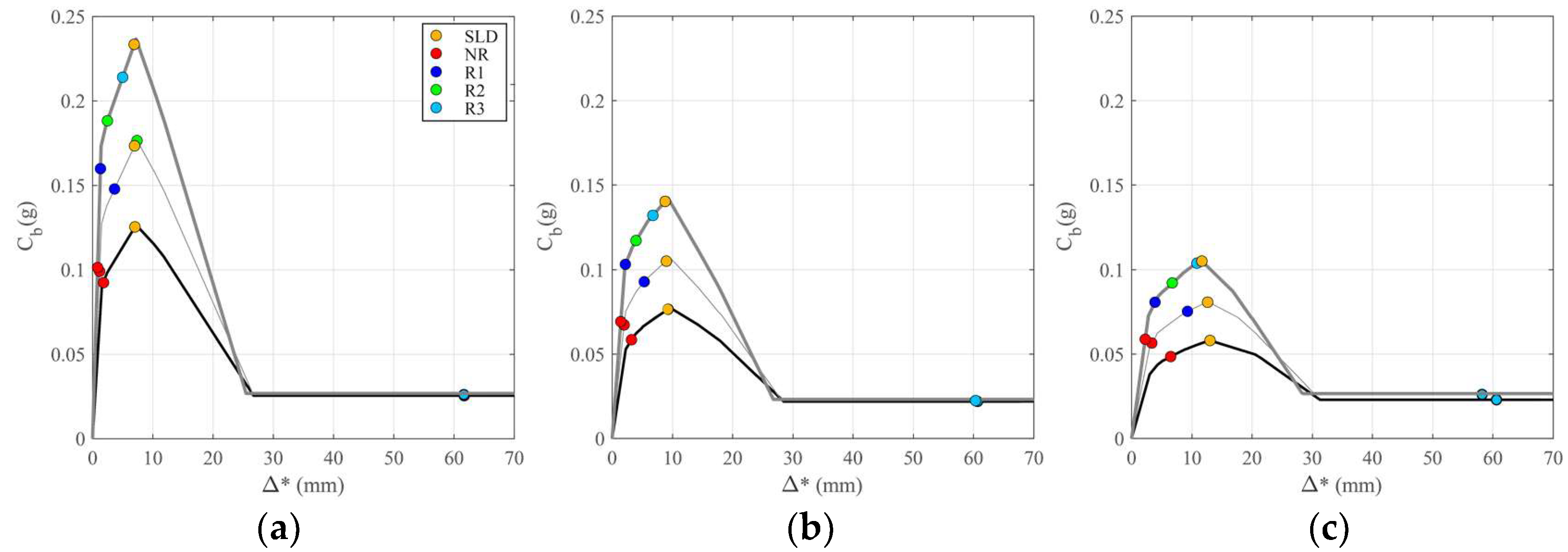
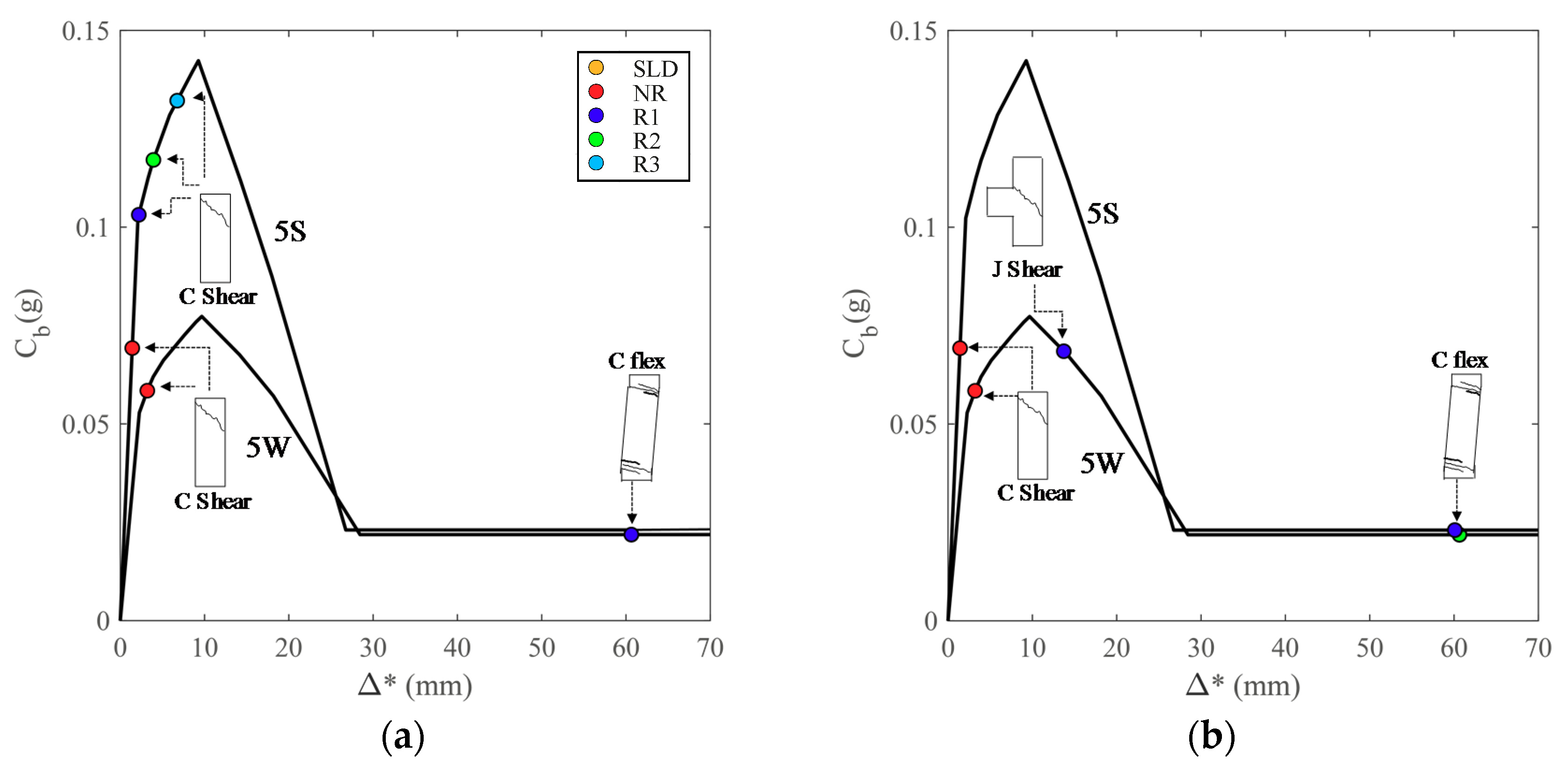
3.1. Lateral Seismic Capacity for As-Built and Retrofitted Configurations

Each building model is analyzed with simplified pushover analysis in both the longitudinal and the transversal direction and considering mode and mass proportional lateral load distribution. Figure 8 shows the capacity curves obtained in transversal direction for mass proportional loads for 3 (a), 5 (b) and 7 (c) storey buildings and considering W (black line), M (thin gray line) and S infills (thick gray line). SLD and SLV limit states are plotted as yellow and red dots along the curves. Only the transversal direction is represented because it corresponds to the lower capacity in terms of PGA. Apparently, the SLD limit state is not significantly influenced by the infill type. However, the PGAc,SLD is higher for stronger infills; for example PGAc,SLD increases from 0.06 g to 0.11 g from 3W to 3S or from 0.04 g to 0.06 g from 7W to 7S. This happens due to the increased stiffening effect for S configurations, that leads to lower T* and to a consequently higher PGA capacity. Additionally, from Figure 8 it is noted that the attainment of SLV limit state is premature and occurs before the SLD limit state; this is due to brittle failure of columns or of exterior unconfined nodes (see Figure 4) according to the code criteria [39]. This circumstance is common for existing buildings designed only for gravity loads and not respecting capacity design principles [55]. On the other hand, these types of brittle failures can be avoided with application of local retrofit interventions. In this study we simulate two possible type of retrofit solutions. The first one, named FRP-only, corresponds to the application of quadriaxial CFRP fabric for unconfined lateral joints as well as strengthening of the columns with continuous uniaxial CFRP strips; three increasing levels of retrofit are considered, namely R1, R2 and R3, corresponding to the application of 1, 2, or 3 plies of FRP for the elements (i.e., exterior beam column joints or columns) that are not verified at the SLV limit state. Second type, named FRP + SRP, that is analogous to the first one, but in addition to FRP, also SRP uniaxial system is disposed around the beam column–joint prior to application of CFRP quadriaxial fabric. Both types of retrofit can be modeled as described in Section 2.4.
Table 1 resumes the results of the pushover analyses with mass and mode proportional horizontal forces and the capacity at SLV limit state for all the considered cases, i.e., for buildings of 3, 5, and 7 storeys with W, M, and S infills configuration and considering the no retrofit NR as well as R1, R2, and R3 retrofit levels for FRP-only and FRP + SRP retrofit solutions. Note that SRP is designed to avoid infill-induced failure and no different retrofit levels are considered as in the case of FRP (i.e., R1, R2, and R3). The mechanism type, when ductile behavior is fully exploited, is always local mechanism at the first storey, except for the case of mode proportional forces and 7W configuration, where the soft storey is at the second level. The table indicates the PGAc,SLV (g) that is attained for each case. Note that the maximum value of PGAc,SLV (g) for each building configuration corresponds to a ductile type mechanism (indicated as PGAc,ductile and reported in bold in Table 1). The table displays also the type of failure for each case, indicated as nS-C and nS-J for column failure (brittle or ductile) or joint failure at nth storey, respectively. If the PGAc,SLV < PGAc,ductile the failure is brittle, either for joints or for columns in shear. Applying either the first or the second type of retrofit the attainment of SLV limit state is significantly delayed and the lateral seismic capacity increases. However, the effect is sensibly different, especially for the configurations with strong S infills. Blue, green, and cyan dots along the pushover curves in Figure 8 represent the varied SLV limit states corresponding to R1, R2, and R3 of FRP-only solution. As it can be seen from the figures and Table 1, for the case of W infills, it is sufficient the R1 level of FRP-only solution (except for 3W for which R2 level is needed) to allow developing of a ductile type mechanism (in this case blue, green, and cyan dots are superimposed in Figure). On the other hand, for S infills, even increasing significantly the retrofit level (e.g., from R1 to R3), the seismic capacity corresponding to the formation of a ductile type mechanism is not reached. For the weak W configuration PGAc,SLV varies from 0.022 g to 0.15 g for the 3W configuration, from 0.017 g to 0.15 g for 5W, and from 0.026 g to 0.14 g for 7W with the R1 level. On the other hand, for the S configuration, even the R3 retrofit level does not allow the structure to reach the displacement capacity on the plateau of the pushover curve: correspondingly, PGAc,SLV varies from 0.02 g to 0.03 g, 0.06 and 0.09 for the 3S configuration, and for R1, R2, and R3 levels, from 0.016 g to 0.024 g, 0.043 and 0.06 for 5S R1, R2, and R3, and from 0.014 g to 0.024 g, 0.04 g, and 0.055 g for 7S R1, R2, and R3, respectively.
Figure 9a schematically represents the effect of the FRP-only retrofit for the case of 5W and 5S configurations. C shear (J shear) in figure indicates brittle shear failure in column (corner joint) and C flex indicates ductile failure in the column.
Analogously to Figure 9a,b schematically represents the effect of the FRP + SRP retrofit for the case of 5W and 5S configurations. In this case, differently from FRP-only solution, the retrofit level R1 allows the change of failure type and with level R2 retrofit (R1 for strong infills) the full lateral seismic capacity, corresponding to a ductile mechanism, is exploited.
The scarce increase of PGAc,SLV for the case of strong infills is due to the significant increment of shear load on columns that is transferred from the adjacent strong infills to the columns and to the consequent brittle failure in shear of the columns. On the other hand, when FRP + SRP strengthening solution is applied, the negative effect of the horizontal action transferred from the infills to adjacent columns is avoided and, even in the case of S infills, it is generally sufficient the retrofit level R1 to attain full development of the ductile type mechanism. Figure 10a–c show the same capacity curves as in Figure 8, but the SLV limit states corresponding to R1, R2, and R3 of FRP + SRP solution are displayed along the curves (instead of FRP-only as in Figure 8).
As it can be seen, when the transferring of horizontal action from the infills to adjacent columns is prevented, by application of SRP reinforcement, for most of the considered cases it is sufficient the retrofit level R1 to allow exploiting a ductile type mechanism. This is confirmed by the increase of PGAc,SLV that is attained even by the application of the R1 retrofit level for either the W and the S configurations. Indeed, PGAc,SLV varies from 0.022 g to 0.15 g for the 3W configuration R1 level, from 0.017 g to 0.055 g for 5W R1, to 0.15 for 5W R2, and from 0.026 g to 0.14 g for 7W with the R1 level. For the case of FRP + SRP similar results are obtained for the S configuration: PGAc,SLV varies from 0.020 g to 0.15 g for the 3S configuration R1 level, from 0.016 g to 0.14 g for 5S R1, and from 0.014 g to 0.15 g for 7S with the R1 level.

3.2. Sensitivity Analysis

Considering the archetype buildings and models introduced in the previous section, a sensitivity analysis is carried out introducing possible variability of infill consistency. In particular, a Monte Carlo simulation is performed for each considered infill configuration, W, M and S, where the tw is not varied with respect to previous assumptions, while Gw is varied assuming a lognormal distribution with median values indicated in Section 3 and considering a COV = 30% for each building. For each of the obtained configurations the PGAc,SLD, and PGAc,SLV, are calculated as described in Section 2.3.
Figure 11 shows the variation of PGAc,SLD with Gwtw. As observed in Section 3.1, the seismic capacity at the SLD limit state tends to increase from weaker infills (represented by lower Gwtw) to stronger ones. This is mainly due to the increase in lateral stiffness and to the consequent lowering of equivalent period T* and related seismic drift demand. For the same reason, the seismic capacity at SLD for higher buildings, that are characterized by higher T* with respect to shorter buildings, is generally lower.
Figure 12 shows the variation of PGAc,SLV with Gwtw comparing the cases of no retrofit NR and increasing levels of retrofit solution FRP-only (R1 and R2). On ordinates the ratio of PGAc,SLV versus the maximum value that can be reached for the same configuration for a ductile mechanism, PGAc,ductile, is represented.
A decreasing trend of the ratio PGAc,SLV/PGAc,ductile with increasing Gwtw is observed for either the NR and the retrofitted solutions. As a general comment it is noted that for weaker infills, characterized by lower values of the product Gwtw, it is possible a significant enhancement of the seismic capacity with the application of retrofit level R1 or R2 of the FRP-only solution. On the other hand, with increasing infills stiffness and strength, the benefit of seismic strengthening with only FRP is sensibly reduced, with just a minimum capacity increase for stronger infills.
Figure 13 shows the variation of PGAc,SLV/PGAc,ductile with Gwtw comparing the cases of no retrofit NR and increasing levels of retrofit solution FRP + SRP (R1 and R2). Differently from previous case, where the presence of increasing level of horizontal actions transferred from infills to adjacent columns and the consequent brittle failure of columns penalizes the capacity of stronger infills configurations, here the PGAc,SLV for the retrofitted solutions increases with Gwtw. In particular, for most of the R1 cases in three-storey and five-storey buildings, it is observed an increasing capacity growth with Gwtw and for seven-storey building the R1 retrofit level allows to reach PGAc,ductile even for weaker infills (lower Gwtw) configurations. In some cases, not evident in figure because the points are overlapped with R2 retrofit level, it can happen that R1 is enough to reach PGAc,ductile even for the three- and five-storey buildings with lower Gwtw.

4. Discussion

An investigation on the effect of infills on the lateral seismic capacity of existing gravity load designed GLD reinforced concrete RC infilled frames was performed. Possible brittle failures in unconfined lateral joints or in columns, that are a common cause of collapse for existing RC buildings not designed for seismic loads or with obsolete seismic provisions, were explicitly considered for the evaluation of seismic capacity. Archetype buildings representative of existing gravity load designed RC frames of three different height ranges (three-, five-, and seven-storey) were obtained with a simulated design process and studied via simplified pushover analyses, including the effect of the infills and considering frame-infill interaction. Three different infills consistency are considered in the analyses, namely weak, medium and strong. The information on infill consistency is generally missing in large scale vulnerability studies. However, this information is collected in the interview-based Cartis form [60], recently implemented by Italian Civil Protection.
Moreover, possible alternative local retrofit interventions devoted to avoiding brittle failures were considered, evaluating their relative efficacy in case of weak or stronger infills. Additionally, a sensitivity analysis was performed to assess the influence of infills consistency variation on the lateral seismic capacity at damage limitation and life safety limit states. Considering the budget constraints that typically affect seismic mitigation campaigns for seismic vulnerable building typologies, which are widespread in Italy, local retrofit interventions are one of the preferred solutions, allowing upgrading of the seismic performance of the buildings as well as the containment of the retrofit costs. Therefore, the results of this paper can give useful preliminary indication on the level of local retrofit solutions required depending on if the infills are strong or weak. Further experimental studies would be beneficial to support the analytical findings from this study.

5. Conclusions

The study evidenced that for the archetype analyzed existing GLD buildings, designed in absence of seismic provisions and of capacity design rules, the attainment of SLV limit state is premature and occurs before the SLD limit state; this is due to brittle failure of columns or of exterior unconfined nodes. The lateral seismic capacity at SLV limit state can be increased by the application of local retrofit interventions, allowing to avoid the brittle failure types for the upgraded elements. However, the efficacy of the retrofit intervention varies depending on the consistency of infills.
If FRP-only retrofit solution is applied in critical elements or joints (FRP strengthening of unconfined lateral joints as well as of the columns in shear), it is noted that as the infills consistency increases the benefit of the retrofit reduces, and in general for stronger infills just a minimum capacity enhancement is attained even adopting increasing level, and costs, of retrofit. For weaker infills a higher benefit in terms of seismic capacity is observed, although it is generally not possible to reach the capacity corresponding to the full development of a ductile type mechanism, even with higher levels of retrofit. This trend mainly depends on the effect of the concentrated horizontal action transferred from the infills to the surrounding frame elements: the shear increase, that is higher for stronger infills, determines a premature shear brittle failure in the columns that can be hardly avoided even with application of a high level of retrofit (e.g., R3 in the example). For weaker infills the concentrated lateral action is lower, and it is easier to prevent brittle failures with application of local retrofit interventions.
However, a significantly higher benefit can be obtained adopting the FRP + SRP retrofit solution, where in addition to FRP strengthening of unconfined lateral joints and of the columns in shear, steel reinforced polymer SRP strips are applied to withstand horizontal action due to infills. In this case, it is observed that the capacity increases as the infills consistency grows for the case of three and five storeys and considering a primary level of building retrofit (R1 in the example), while for a higher retrofit level (R2 in the example) it is always possible to attain the lateral seismic capacity corresponding to a ductile type mechanism. In fact, the application of a specific local reinforcement, the SRP strips, allows to absorb the high concentrated action that is transferred from the infills and the full exploitation of the benefic effect of the FRP retrofitting of joints and columns in shear. When the aggravating effect of concentrated shear due to frame-infill interaction is mitigated (e.g., through SRP strips or similar solution based on the same principle) the infills consistency does not limit anymore the full exploitation of lateral seismic capacity. On the contrary, the application of a relatively low level of retrofit (R1 in the example), allows obtaining an increasing level of capacity enhancement for stronger infills.

Author Contributions

M.P., M.G.d.A, and M.D.L. collected scientific articles for state of the art. M.G.d.A. performed the analyses, analyzed the results, and contributed to writing the paper. M.P. organized the work, contributed to the analyses of the results, and to writing the paper. M.D.L. gave advice on the alternative retrofit strategies and contributed to the analyses of results. A.P. contributed to the analyses of results and revised the paper for overall consistency and scopes.

Acknowledgments

This study was performed in the framework of PE 2018; joint program DPC-Reluis Subproject RC-WP1: vulnerability of RC construction at the territorial scale and Subproject TT: Territorial themes.

Conflicts of Interest

The authors declare no conflict of interest.

References

  1. Grunthal, G. (Ed.) Chaiers du Centre Européen de Géodynamique et de Séismologie: Volume 15—European Macroseismic Scale 1998; European Center for Geodynamics and Seismology: Luxembourg, 1998. [Google Scholar]
  2. Rojah, C. ATC-20-1 Field Manual: Postearthquake Safety Evaluation of Buildings; Applied Technology Council: Redwood City, CA, USA, 2005. [Google Scholar]
  3. Polese, M.; Gaetani d’Aragona, M.; Di Ludovico, M.; Prota, A. Sustainable selective mitigation interventions towards effective earthquake risk reduction at the community scale. Sustainability 2018, 10, 2894. [Google Scholar] [CrossRef]
  4. Bazzurro, P.; Mollaioli, F.; De Sortis, A.; Bruno, S. Effects of masonry walls on the seismic risk of reinforced concrete frame buildings. In Proceedings of the 8th US National Conference on Earthquake Engineering and Seismology, San Francisco, CA, USA, 18–22 April 2006. [Google Scholar]
  5. Borzi, B.; Crowley, H.; Pinho, R. The influence of infill panels on vulnerability curves for RC buildings. In Proceedings of the 14th World Conference on Earthquake Engineering, Beijing, China, 12–17 October 2008. [Google Scholar]
  6. Negro, P.; Colombo, A. Irregularities induces by nonstructural masonry panels in framed buildings. Eng. Struct. 1997, 19, 576–585. [Google Scholar] [CrossRef]
  7. Dolšek, M.; Fajfar, P. Soft storey effects in uniformly infilled reinforced concrete frames. J. Earthq. Eng. 2001, 5, 1–12. [Google Scholar] [CrossRef]
  8. Fardis, M.N. Seismic design issues for masonry-infilled RC frames. In Proceedings of the First European Conference on Earthquake Engineering and Seismology, Geneva, Switzerland, 3–8 September 2006. [Google Scholar]
  9. Comité Euro-International du Béton (CEB). RC Frames under Earthquake Loading: State of the Art Report; Bulletin 231; Thomas Telford Ltd.: London, UK, 1996. [Google Scholar]
  10. Kakaletsis, D.J.; David, K.N.; Karayannis, C.G. Effectiveness of some conventional seismic retrofitting techniques for bare and infilled R/C frames. Struct. Eng. Mech. 2011, 39, 499–520. [Google Scholar] [CrossRef]
  11. Calvi, G.M.; Bolognini, D.; Penna, A. Seismic performance of masonry-infilled RC frames: Benefits of slight reinforcement. In Proceedings of the Sismica 2004-6° Congresso Nacional de Sismologia e Engenharia Sismica, 14–15 April 2004; Available online: ftp://ftp.ecn.purdue.edu/spujol/Mason/New%20Folder/253-276_G_Michele_Calvi.pdf (accessed on 27 September 2018).
  12. Akyuz, U.; Yakut, A.; Ozturk, M.S. Effect of masonry infill walls on the lateral behavior of buildings. In Proceedings of the First European Conference on Earthquake Engineering and Seismology, Geneva, Switzerland, 3–8 September 2006. [Google Scholar]
  13. Gaetani d’Aragona, M.; Polese, M.; Prota, M. Influence factors for the assessment of maximum lateral seismic deformations in Italian multistorey RC buildings. In Proceedings of the COMPDYN 2017 6th ECCOMAS Thematic Conference on Computational Methods in Structural Dynamics and Earthquake Engineering, Rhodes Island, Greece, 15–17 June 2017. [Google Scholar]
  14. Gaetani d’Aragona, M.; Polese, M.; Cosenza, E.; Prota, A. Simplified assessment of maximum interstory drift for RC buildings with irregular infills distribution along the height. Bull. Earthq. Eng. 2018. [Google Scholar] [CrossRef]
  15. Colajanni, P.; Impollonia, P.; Paia, M. The effect of infill panels models uncertainties on the design criteria effectiveness for RC frames. In Proceedings of the Final Workshop of Joint DPC-RELUIS Project 2005–2008, Rome, Italy, 29–30 May 2008; pp. 401–408. (In Italian). [Google Scholar]
  16. Polese, M.; Verderame, G.M. Seismic capacity of RC infilled frames: A parametric analysis. In Proceedings of the XIII ANIDIS National Conference “Seismic Engineering in Italy”, Bologna, Italy, 28 June–2 July 2009. (In Italian). [Google Scholar]
  17. Dymiotis, C.; Kappos, A.J.; Chryssanthopoulos, M.K. Seismic reliability of masonry-infilled RC frames. J. Struct. Eng. 2001, 127, 296–305. [Google Scholar] [CrossRef]
  18. Celarec, D.; Ricci, P.; Dolšek, M. The sensitivity of seismic response parameters to the uncertain modelling variables of masonry-infilled reinforced concrete frames. Eng. Struct. 2012, 35, 165–177. [Google Scholar] [CrossRef]
  19. Perrone, D.; Leone, M.; Aiello, M.A. Non-linear behaviour of masonry infilled RC frames: Influence of masonry mechanical properties. Eng. Struct. 2017, 150, 875–891. [Google Scholar] [CrossRef]
  20. Comitée Européen de Normalisation. European Standard EN 1998-1: Eurocode8. Design of Structures for Earthquake Resistance. Part 1. General Rules, Seismic Actions and Rules for Buildings; CEN: Brussels, Belgium, 2005. [Google Scholar]
  21. Ministerial Decree, D.M. 20.02.2018 “Updating of Technical Standards for Construction”. Available online: http://www.gazzettaufficiale.it/eli/gu/2018/02/20/42/so/8/sg/pdf (accessed on 27 September 2018).
  22. Fajfar, P. Capacity spectrum method based on inelastic demand spectra. Earthq. Eng. Struct. Dyn. 1999, 28, 979–993. [Google Scholar] [CrossRef]
  23. Verderame, G.M.; Polese, M.; Mariniello, C.; Manfredi, G. A simulated design procedure for the assessment of seismic capacity of existing reinforced concrete buildings. Adv. Eng. Softw. 2010, 41, 323–335. [Google Scholar] [CrossRef]
  24. Polese, M.; Marcolini, M.; Zuccaro, G.; Cacace, F. Mechanism Based Assessment of Damaged-Dependent Fragility curves for RC building classes. Bull. Earthq. Eng. 2015, 13, 1323–1345. [Google Scholar] [CrossRef]
  25. R.D.L. n 2229/1939 Regulations for the Execution of Simple and Reinforced Concrete Constructions. 1939. Available online: http://www.normattiva.it/atto/caricaDettaglioAtto?atto.DataPubblicazioneGazzetta=1940-04-18&atto.codiceRedazionale=039U2232 (accessed on 27 September 2018). (In Italian).
  26. Circolare del Ministero dei Lavori Pubblici n. 1472 del 23/5/1957. Armature delle Strutture in Cemento Armato. 1957. Available online: http://sttan.it/norme/Storiche/1939_11_10_RDL_n_2229_norme_CA.pdf (accessed on 27 September 2018). (In Italian).
  27. Polese, M.; Verderame, G.M.; Manfredi, G. Static vulnerability of existing RC buildings in Italy: A case study. Struct. Eng. Mech. 2011, 39, 599–620. [Google Scholar]
  28. Ricci, P. Seismic Vulnerability of Existing RC Buildings. Ph.D. Thesis, University of Naples Federico II, Naples, Italy, 2018. [Google Scholar]
  29. Mollaioli, F.; Bazzurro, P.; Bruno, S.; De Sortis, A. Influenza della modellazione strutturale sulla risposta sismica di telai in cemento armato tamponati. In Proceedings of the Atti del XIII Convegno ANIDIS “L’ingegneria Sismica in Italia”, Bologna, Italy, 28 June–2 July 2009. (In Italian). [Google Scholar]
  30. Biskinis, D.; Fardis, M.N. Deformations at flexural yielding of members with continuous or lap-spliced bars. Struct. Concr. 2010, 11, 128–138. [Google Scholar] [CrossRef]
  31. Haselton, C.B.; Liel, A.B.; Taylor-Lange, S.; Deierlein, G.G. Beam-Column Element Model Calibrated for Predicting Flexural Response Leading to Global Collapse of RC Frame Buildings; PEER Report 2007; Pacific Engineering Research Center, University of California: Berkeley, CA, USA, 2008; p. 3. [Google Scholar]
  32. Noh, N.M.; Liberatore, L.; Mollaioli, F.; Tesfamariam, S. Modelling of masonry infilled RC frames subjected to cyclic loads: State of the art review and modelling with OpenSees. Eng. Struct. 2017, 150, 599–621. [Google Scholar]
  33. Panagiotakos, T.B.; Fardis, M.N. Seismic response of infilled RC frames structures. In Proceedings of the 11th World Conference on Earthquake Engineering, Acapulco, Mexico, 23–28 June 1996. [Google Scholar]
  34. Fardis, M.N.; Carvalho, E.C.; Fajfar, P.; Pecker, A. Seismic Design of Concrete Buildings to Eurocode 8; CRC Press: Boca Raton, FL, USA, 2015. [Google Scholar]
  35. Mainstone, R.J. On the Stiffnesses and Strengths of Infilled Frames. In Proceedings of the Institution of Civil Engineering, Supplement IV, London, UK, 1971; pp. 57–90. Available online: https://copac.jisc.ac.uk/id/38779199?style=html&title=ON%20THE%20STIFFNESS%20AND%20STRENGTHS%20OF%20INFILLED%20FRAMES (accessed on 27 September 2018).
  36. Morandi, P.; Hak, S.; Magenes, G. Performance-based interpretation of in-plane cyclic tests on RC frames with strong masonry infills. Eng. Struct. 2018, 156, 503–521. [Google Scholar] [CrossRef]
  37. Di Trapani, F.; Macaluso, G.; Cavaleri, L.; Papia, M. Masonry infills and RC frames interaction: Literature overview and state of the art of macromodeling approach. Eur. J. Environ. Civ. Eng. 2015, 19, 1059–1095. [Google Scholar] [CrossRef]
  38. Ricci, P.; Verderame, G.M.; Manfredi, G. Simplified analytical approach to seismic vulnerability assessment of Reinforced Concrete buildings. In Proceedings of the XIV Convegno ANIDIS “L’ingegneria Sismica in Italia”, Bari, Italy, 18–22 September 2011. [Google Scholar]
  39. Circolare del Ministero dei Lavori Pubblici n. 617 del 2/2/2009. Istruzioni per L’applicazione delle “Nuove Norme Tecniche per le Costruzioni” di cui al D.M. 14 Gennaio 2008. G.U. n. 47 del 26/2/2009. 2009. Available online: http://www.gazzettaufficiale.it/eli/id/2009/02/26/09A01318/sg (accessed on 27 September 2018). (In Italian).
  40. Fabbrocino, G.; Verderame, G.M.; Polese, M. Probabilistic steel stress–crack width relationship in RC frames with smooth rebars. Eng. Struct. 2007, 29, 1–10. [Google Scholar] [CrossRef]
  41. Gaetani d’Aragona, M.; Polese, M.; Elwood, K.; Baradaran Shoraka, M.; Prota, A. Aftershock collapse fragility curves for non-ductile RC buildings: A scenario-based assessment. Earthq. Eng. Struct. Dyn. 2017, 46, 2083–2102. [Google Scholar] [CrossRef]
  42. Comitée Européen de Normalisation, European Standard EN 1998-3: Eurocode 8: Design of Structures for Earthquake Resistance, Part 3: Assessment and Retrofitting of Buildings. 2005. Available online: https://www.saiglobal.com/PDFTemp/Previews/OSH/IS/EN/2005/I.S.EN1998-3-2005.pdf (accessed on 27 September 2018).
  43. Celarec, D.; Dolšek, M. Practice-oriented probabilistic seismic performance assessment of infilled frames with consideration of shear failure of columns. Earthq. Eng. Struct. Dyn. 2013, 42, 1339–1360. [Google Scholar] [CrossRef]
  44. Verderame, G.M.; De Luca, F.; Ricci, P.; Manfredi, G. Preliminary analysis of a soft-storey mechanism after the 2009 L’Aquila earthquake. Earthq. Eng. Struct. Dyn. 2011, 40, 925–944. [Google Scholar] [CrossRef]
  45. FEMA 308 Repair of Earthquake Damaged Concrete and Masonry Wall Buildings; Federal Emergency Management Agency: Washington, DC, USA, 1998.
  46. Polese, M.; Marcolini, M.; Gaetani d’Aragona, M.; Cosenza, E. Reconstruction policies: Explicitating the link of decisions thresholds to safety level and costs for RC buildings. Bull. Earthq. Eng. 2017, 15, 759–785. [Google Scholar] [CrossRef]
  47. Polese, M.; Di Ludovico, M.; Marcolini, M.; Prota, A.; Manfredi, G. Assessing reparability: Simple tools for estimation of costs and performance loss of earthquake damaged RC buildings. Earthq. Eng. Struct. Dyn. 2015, 44, 1539–1557. [Google Scholar] [CrossRef]
  48. Polese, M.; Di Ludovico, M.; Prota, A. Post-earthquake reconstruction: A study on the factors influencing demolition decisions after 2009 L’Aquila earthquake. Soil Dyn. Earthq. Eng. 2018, 105, 139–149. [Google Scholar] [CrossRef]
  49. Dolšek, M.; Fajfar, P. Inelastic spectra for infilled reinforced concrete frames. Earthq. Eng. Struct. Dyn. 2004, 33, 1395–1416. [Google Scholar] [CrossRef]
  50. Dolšek, M.; Fajfar, P. Simplified non-linear seismic analysis of infilled reinforced concrete frames. Earthq. Eng. Struct. Dyn. 2005, 34, 49–66. [Google Scholar] [CrossRef]
  51. Gaetani d’Aragona, M.; Polese, M.; Prota, A. Relationship between the variation of seismic capacity after damaging earthquakes, collapse probability and repair costs: Detailed evaluation for a non-ductile building. In Proceedings of the 15th ECCOMAS Thematic Conference on Computational Methods in Structural Dynamics and Earthquake Engineering, Crete Island, Greece, 25–27 May 2015. [Google Scholar]
  52. Fédération Internationale du Beton (FIB). Seismic Assessment and Retrofit of Reinforced Concrete Buildings Externally Bonded FRP Reinforcement for RC Structures, Bulletin 24; FIB: Lausanne, Switzerland, 2003; p. 312. [Google Scholar]
  53. Ilki, A.; Tore, E.; Demir, C.; Comert, M. Seismic Performance of a Full-Scale FRP Retrofitted Sub-standard RC Building. In Recent Advances in Earthquake Engineering in Europe: 16th European Conference on Earthquake Engineering, Thessaloniki, 2018; Springer International Publishing: New York, NY, USA, 2018; pp. 519–544. [Google Scholar]
  54. Del Vecchio, C.; Di Ludovico, M.; Prota, A.; Manfredi, G. Analytical model and design approach for FRP strengthening of non-conforming RC corner beam–column joints. Eng. Struct. 2015, 87, 8–20. [Google Scholar] [CrossRef]
  55. Frascadore, R.; Di Ludovico, M.; Prota, A.; Verderame, G.M.; Manfredi, G.; Dolce, M.; Cosenza, E. Local strengthening of reinforced concrete structures as a strategy for seismic risk mitigation at regional scale. Earthq. Spectra 2015, 31, 1083–1102. [Google Scholar] [CrossRef]
  56. CNR-DT 200 R1/2013. Guide for the Design and Construction of Externally Bonded FRP Systems for Strengthening Existing Structures e Materials, RC and PC Structures, Masonry Structures. 2013. Italian National Research Council. Available online: https://www.cnr.it/it/node/2620 (accessed on 27 September 2018).
  57. ASCE-SEI 41-06, Seismic Rehabilitation of Existing Buildings, ASCE Standard; American Society of Civil Engineers: Reston, VA, USA, 2007.
  58. Del Zoppo, M.; Di Ludovico, M.; Balsamo, A.; Prota, A.; Manfredi, G. FRP for seismic strengthening of shear controlled RC columns: Experience from earthquakes and experimental analysis. Compos. Part B 2017, 129, 47–57. [Google Scholar] [CrossRef]
  59. Hak, S.; Morandi, P.; Magenes, G.; Sullivan, T.J. Damage control for clay masonry infills in the design of RC frame structures. J. Earthq. Eng. 2012, 16 (Suppl. 1), 1–35. [Google Scholar] [CrossRef]
  60. Zuccaro, G.; Dolce, M.; De Gregorio, D.; Speranza, E.; Moroni, C. La Scheda CARTIS per la Caratterizzazione Tipologico-Strutturale dei Comparti Urbani Costituiti da Edifici Ordinari. Valutazione Dell’esposizione in Analisi di Rischio Sismico. In Proceedings of the GNGTS 2015. Available online: http://www3.ogs.trieste.it/gngts/files/2015/S23/Riassunti/Zuccaro.pdf (accessed on 27 September 2018). (In Italian).
Figure 1. Schematic representation of the generic frame of the building with identification of the columns and infill panels and the nonlinear model adopted for each of these elements. The two panels on the right schematize frame-infill interaction and modeling approach to capture shear demand on columns and joints.
Buildings 08 00137 g001
Figure 2. Moment-rotation relationship for RC columns (a) and the corresponding V-Δ diagram (b). In (b) also the additional shear on columns induced by infill panels is shown, along with the adopted shear capacity model for not retrofitted building and for different retrofit options.
Buildings 08 00137 g002
Figure 3. Lateral force–displacement relationship for infill panels.
Buildings 08 00137 g003
Figure 4. Interaction between infills and RC structural members. (a) Damage to column and joint, (b) detail.
Buildings 08 00137 g004
Figure 5. Pushover curve and evaluation of lateral seismic capacity with spectral approach (a) Pushover curve and the quadrilinear idealization according to [50]; and (b) the application of capacity spectrum method for evaluation of the capacity.
Buildings 08 00137 g005
Figure 6. Local retrofit solutions for columns and joints: (a) application of SRP uniaxial system to withstand horizontal action due to infills and quadriaxial CFRP fabric for corner joint (b); and shear strengthening of the columns with uniaxial CFRP strips (c).
Buildings 08 00137 g006
Figure 7. Scheme of the archetype buildings considered for the analyses.
Buildings 08 00137 g007
Figure 8. Capacity curves for the archetype buildings in transversal direction with mass proportional loads: (a) three-storey, (b) five-storey, and (c) seven-storey building with W (black), M (gray thin) and S (gray thick) infills. Limit states for no retrofit NR and increasing retrofit levels of FRP-only solution are represented along the curves.
Buildings 08 00137 g008
Figure 9. Pushover curves for 5W and 5S configurations and failure mechanisms for the NR and (a) R1, R2, and R3 FRP-only retrofit solutions and (b) R1, R2, and R3 FRP + SRP retrofit solutions.
Buildings 08 00137 g009
Figure 10. Capacity curves for the archetype buildings in transversal direction with mass proportional loads: (a) three-storey (b) five-storey, and (c) seven-storey building with W (bold black), M (thin gray) and S (bold gray) infills. Limit states for no retrofit NR and increasing retrofit levels of FRP + SRP solution are represented along the curves.
Buildings 08 00137 g010
Figure 11. Variation of PGAc,SLD with Gwtw for (a) three-storey, (b) five-storey, and (c) seven-storey buildings.
Buildings 08 00137 g011
Figure 12. Variation of PGAc,SLV/PGAc,ductile with Gwtw for (a) three-storey, (b) five-storey, and (c) seven-storey buildings. The effect of retrofit solution FRP-only is also represented.
Buildings 08 00137 g012
Figure 13. Variation of PGAc,SLV/ PGAc,ductile with Gwtw for (a) three-storey, (b) five-storey, and (c) seven-storey building. The effect of retrofit solution FRP + SRP is also represented.
Buildings 08 00137 g013
Table 1. PGAc,SLV (g) for the archetype buildings with W, M and S infills configurations and for mass/mode analyses. No retrofit NR and R1, R2 R3 increasing retrofit levels are considered for FRP-only and FRP + SRP retrofit solutions. nS-C and nS-J indicates column failure (brittle or ductile) or joint failure at the nth storey, respectively.
FRP-OnlyFRP + SRP
ModelNRR1R2R3R1R2R3
3W0.022/0.0240.022/0.0240.151/0.1410.151/0.1410.151/0.0770.151/0.1410.151/0.141
1S-C/1S-C1S-C/1S-C1S-C/1S-C1S-C/1S-C1S-C/1S-J1S-C/1S-C1S-C/1S-C
3M0.02/0.020.060/0.0650.085/0.0940.145/0.1400.145/0.1400.145/0.1400.145/0.140
1S-C/1S-C1S-C/1S-C1S-C/1S-C1S-C/1S-C1S-C/1S-C1S-C/1S-C1S-C/1S-C
3S0.020/0.0220.032/0.0350.060/0.0640.093/0.0980.147/0.1480.147/0.1480.147/0.148
1S-C/1S-C1S-C/1S-C1S-C/1S-C1S-C/1S-C1S-C/1S-C1S-C/1S-C1S-C/1S-C
5W0.017/0.0180.148/0.1360.148/0.1360.148/0.1360.055/0.1360.148/0.1360.148/0.136
1S-C/1S-C1S-C/1S-C1S-C/1S-C1S-C/1S-C1S-J/1S-C1S-C/1S-C1S-C/1S-C
5M0.015/0.0160.038/0.0440.146/0.1370.146/0.1370.146/0.1370.146/0.1370.146/0.137
1S-C/1S-C1S-C/1S-C1S-C/1S-C1S-C/1S-C1S-C/1S-C1S-C/1S-C1S-C/1S-C
5S0.015/0.0160.024/0.0250.043/0.0470.060/0.0700.142/0.0950.142/0.1380.142/0.138
1S-C/1S-C1S-C/1S-C1S-C/1S-C1S-C/1S-C1S-C/1S-J1S-C/1S-C1S-C/1S-C
7W0.026/0.0200.139/0.1250.139/0.1250.139/0.1250.139/0.1250.139/0.1250.139/0.125
1S-C/2S-C1S-C/2S-C1S-C/2S-C1S-C/2S-C1S-C/2S-C1S-C/2S-C1S-C/2S-C
7M0.016/0.0140.040/0.0440.145/0.1380.145/0.1380.145/0.1380.145/0.1380.145/0.138
1S-C/2S-C1S-C/2S-C1S-C/1S-C1S-C/1S-C1S-C/1S-C1S-C/1S-C1S-C/1S-C
7S0.014/0.0140.024/0.0260.039/0.0470.055/0.0700.146/0.1420.146/0.1420.146/0.142
1S-C/3S-C1S-C/1S-C1S-C/1S-C1S-C/1S-C1S-C/1S-C1S-C/1S-C1S-C/1S-C

