1. Introduction
Projects in the domain of architecture, engineering and construction (AEC) typically involve diverse parties, each bringing specific information into these projects. Client information needs to be combined with the information of the architectural design firm; electrical engineering information needs to be combined with facility management information; plumbing information needs to be combined with sensor information; and so forth. Also after the construction phase, building information needs to be accessible for a range of diverse users, including the facility director, in-house machinery and systems, renovation specialists, technicians, and so forth. As a result, a well-functioning information flow throughout the complete building life-cycle is crucial. In this context, the following research question has remained an important challenge that needs to be addressed.
How can all AEC information be combined so that it is comfortably accessible to the diverse parties involved in the appropriate time and format?
This research question is typically referred to as a question of interoperability, but it also involves important questions regarding process modelling and management throughout the whole building life-cycle. In Curry
et al. [
1], this second element is described as the inability of current methods and tools “
to account for the profile of building managers, both in terms of the operational context of their role, and their typical technical and educational background ” [
2]. We will refer to this element here as a
functionality mismatch issue, indicating that a mismatch exists between the functionality that is provided by information systems and the functionality expected by end users. If the operational context and the background of the end user needs to be taken into account in order to address this functionality mismatch issue, then the process of which this user is part, is of tremendous importance. Addressing this issue will thus not only require technological innovations, but likely also process innovations.
Diverse European and international research initiatives have been addressing the interoperability issue already. The Building Information Modelling (BIM) strategy [
3] is one of the most notable of the suggested approaches. The BIM strategy appeared to bring about improved facilities for information management in AEC projects. Although a lot of improvements have been generated by the usage of such BIM environments, they are not entirely successful in addressing the above interoperability and functionality mismatch challenge. Difficulties persist regarding information interoperability, also when relying on the Industry Foundation Classes (IFC) [
4] as a standard for information exchange. Also the relation between end user and information system did not entirely improve, because BIM environments typically prove not to be flexible enough to house the specific kinds of information of the diverse parties involved in the building life-cycle. In the end, also a BIM environment provides but one “silo” of information to the end user, with the contained information often not being customised or tailored to the needs and requirements of the end user.
Semantic web technologies, as they were suggested in Berners-Lee
et al. [
5], might provide better answers to the above questions. These technologies currently lie at the basis of a global Linked Open Data (LOD) cloud [
6,
7]. Similar to how semantic web technologies allow to link various silos of data in one LOD cloud, they might also allow to effectively connect the diverse information models available in AEC projects throughout the building life-cycle. With this global source of cross-domain information, also the end user experience might eventually be improved, because applications can theoretically rely on a larger and more diverse information source (see also Cyganiak and Jentzsch [
8]).
In this article, we will first look into existing approaches aiming at an improved information flow, i.e., information management and exchange, in the AEC domain. Then we look more closely into the ways in which semantic web technologies can help in integrating information models in the AEC domain. More precisely, we will look into the ways in which the connecting links between information models can be created and managed. This approach is then considered as a possible technological change that might also accommodate the process-oriented changes required to address both the interoperability and the functionality mismatch issue. Finally, a short indication is given of anticipated use cases for deploying and benefiting from linked data in terms of decision-making support during the building life-cycle.
2. The Central Issue: Information Flow
The amount and diversity of information is one of the most notable characteristics of a project in the AEC domain. Many domain experts with different backgrounds typically meet within the context of a building project, each of them composing a personal understanding of the building design and providing with this personal understanding a specific contribution to the project. Additionally, each of these experts relies on diverse software tools, which causes a multiplication of the number of information structures at play in a project. The following information structures are just a few of the many structures used in a design and construction project.
“designerly” information managed by the architect:
How are certain elements altered by design decisions? What are the motivations behind specific design decisions? How are specific design requirements addressed in the design?
material information managed by diverse construction partners:
What materials are certain design elements made of? What are material characteristics of specific construction elements? How much are the building costs? What are the known advantages and disadvantages of using specific construction elements in certain contexts?
structural information managed by structural engineers:
Which elements are central in bearing specific user-loads? How do elements behave in their specific location? What are recommended construction techniques for specific building configurations?
and so forth.
Since these information structures are all part of one and the same project—a project that needs to be finished collaboratively—a lot of information flows emerge between these information structures (see schema in
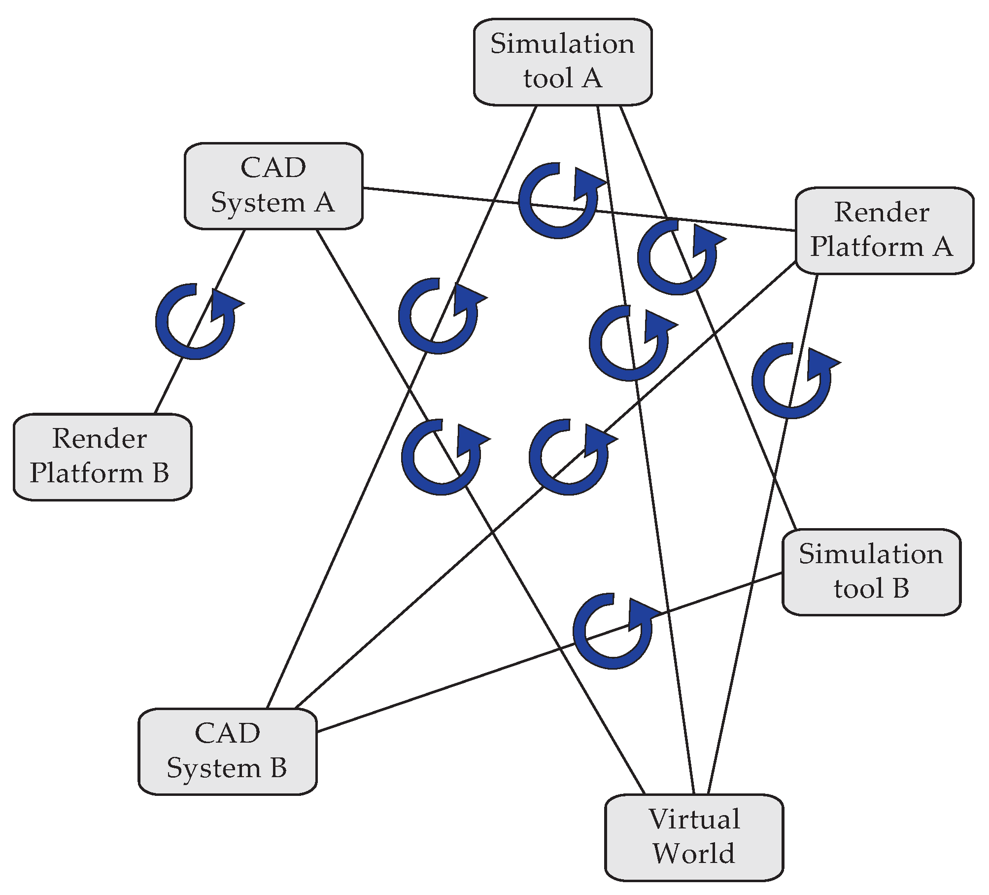
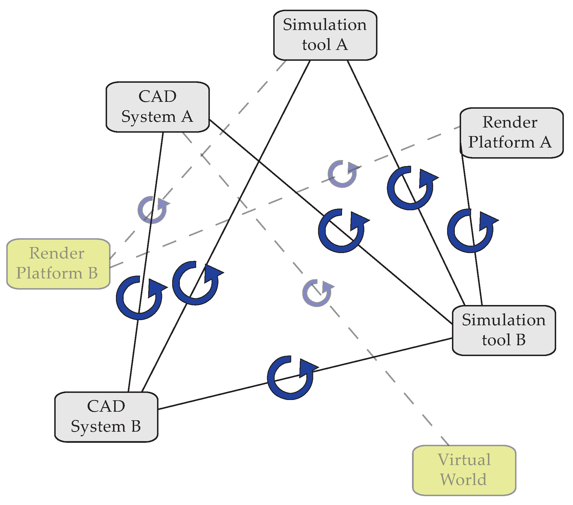
Figure 1). These information flows connect the diverse “information managers” of the project, which are both human users and information systems. The architectural design needs to be communicated to the structural engineer, the structural engineer needs to take into account the design of the electricity engineer, compliance is needed with all kinds of regulations and standards, and so forth. Crucial in this context of continuous information flows are the interface points where two or more understandings come together. In these points, information is interpreted from one understanding or information structure into another, thereby making them sensitive to misconceptions or ‘mistakes’ because of the possible misunderstanding (
Figure 1).
Figure 1.
A schema of the typical process of information exchange in an architecture, engineering and construction (AEC) project, with human users in the outer circle, information systems in the inner circle, and connection lines displaying information exchange routes. Interface points (circular arrows) are points where information is interpreted from one information structure into the other, both between human users and information systems (in red) and among information systems (in blue).
Because of these misconceptions and resulting mistakes, many designers typically switch to a more pragmatic approach in which they use information systems for very specific and limited purposes and “manually” integrate results (see example in Pauwels
et al. [
9]). One could say that computer-aided design (CAD) applications, for instance, are in this case used as “computer-aided drafting” environments. The information systems are in this pragmatic software usage often combined with a lot of traditional techniques, such as paper-based sketching, simplified simulation models, and so forth. In this case, the computer is used as a draughtsman, rather than an oracle or an agent/assistant, to use the terms suggested by Lawson [
10].
Note that this more pragmatic approach is not necessary in all cases. Large architectural design and construction firms are to some extent able to address these issues by developing custom in-house information systems, directly tailored to the needs of the design team. Some successful examples can be named of this approach, namely the “Digital Project” modelling application implemented and used in the office of the architect Frank Gehry [
11], and the reliance on a Specialist Modelling Group (SMG) in the office of Foster and Partners [
12]. Although Digital Project relies on the modelling software “Computer Aided Three-Dimensional Interactive Application” (CATIA), important features were added that were of particular use to the architectural design style of the architect, Gehry. The SMG in Foster and Partners similarly provides custom design tools compliant with specific needs in specific design projects, leading to custom and on-demand assistance in these projects.
In the two following sections, we will indicate to what extent information system support can be improved for the designers that do not have such a specialised programming team at their command. In our investigation, we will distinguish between interface points between two information systems (displayed in blue in
Figure 1) and between a human user and an information system (displayed in red in
Figure 1). These two types of interface points coincide with two major difficulties in information exchange, namely a lack of interoperability among information systems and a mismatch between the functionality provided by information systems and the functionality expected by end users. Whereas the first issue relates to information exchange only, the second issue additionally deals with a layer of functionality. In the two following sections, we will proceed with a discussion of both issues separately.
3. Interoperability among Information Systems
The information flow between information systems is closely related to the notion of interoperability. This is the ability of information systems to connect their information structures and “work together” effectively. Two levels of interoperability can be distinguished: syntactic and semantic interoperability. These terms have a long history of definitions, relations and understandings [
13], but the terms will be used in their traditionally used senses here. Two syntactically interoperable systems describe information using the same syntax, with syntax defined as an “orderly or systematic arrangement of parts or elements” [
14]. Two semantically interoperable systems supposedly have the additional ability to interpret the “signification or meaning” [
14] of the exchanged information and (re)use it. We will concentrate here on semantic interoperability.
Each information system allows one to represent a particular kind of information in a particular semantic model using a specific syntax. This semantic model can be very different though. It might only enable the representation of information in the form of three-dimensional points; it might only enable the representation of information in the form of simple geometric information, such as lines, boxes, spheres, and so forth; and it might only enable the representation of information in the form of a more complex type of information, such as wall types, window types, materials used, design intent and geographical pointers. Information systems in the AEC domain typically represent diverse abstract concepts in concrete terms, including walls, floors, colours, lines, spheres, and so forth. These are only representations of the actual objects, which only have a meaning within their respective semantic domains.
Figure 1, for instance, shows diverse semantic domains, including the semantic domains for CAD Systems A and B, the Virtual World, Simulation Tools A and B, and so forth. The interoperability issue considered in this section is constituted by the lack of an appropriate semantic mapping between two such domains. This semantic mapping is known as the semantic function between two semantic domains. Below, we look into diverse strategies that can be used to produce mappings or semantic functions between semantic domains in the AEC domain and, thus, to address the interoperability issue.
3.1. Sharing Information in the Wild
Information used within a design and construction project can be described in many ways, with both a varying syntax and varying semantics. Additionally, this information is so diverse that no single information structure can describe it all. This results in a large set of specialised information structures between which conversions are inevitable. This naturally evolves into the situation shown in
Figure 2, in which information is being converted from one information structure into the other as needed.
Figure 2.
The traditional information flow between information systems: sharing information “in the wild”. Interface points (circular arrows) are points where information is interpreted from one information structure into the other. In this case, this happens only among information systems (in blue).
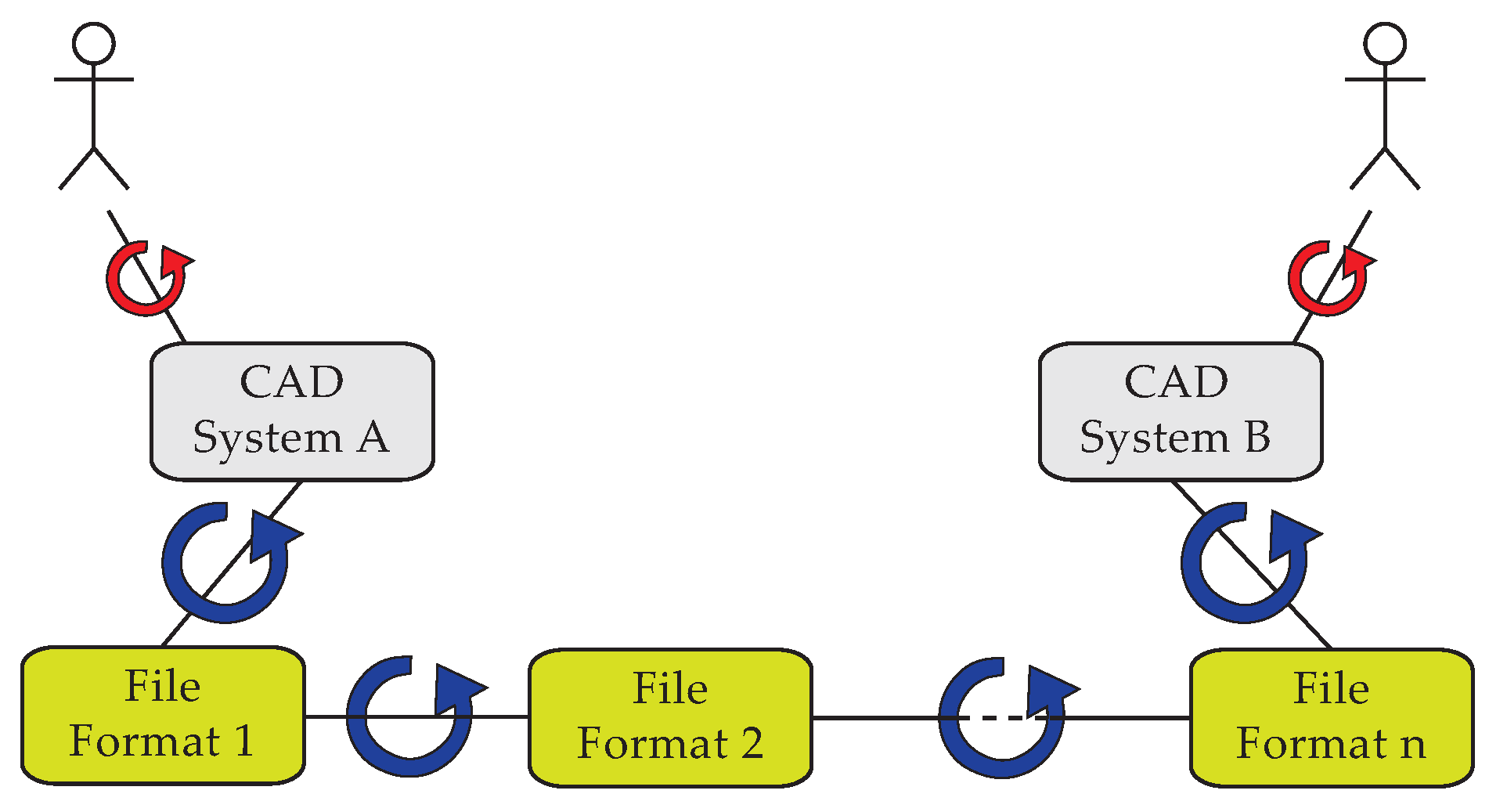
The actual connection between two information systems often looks as is indicated in
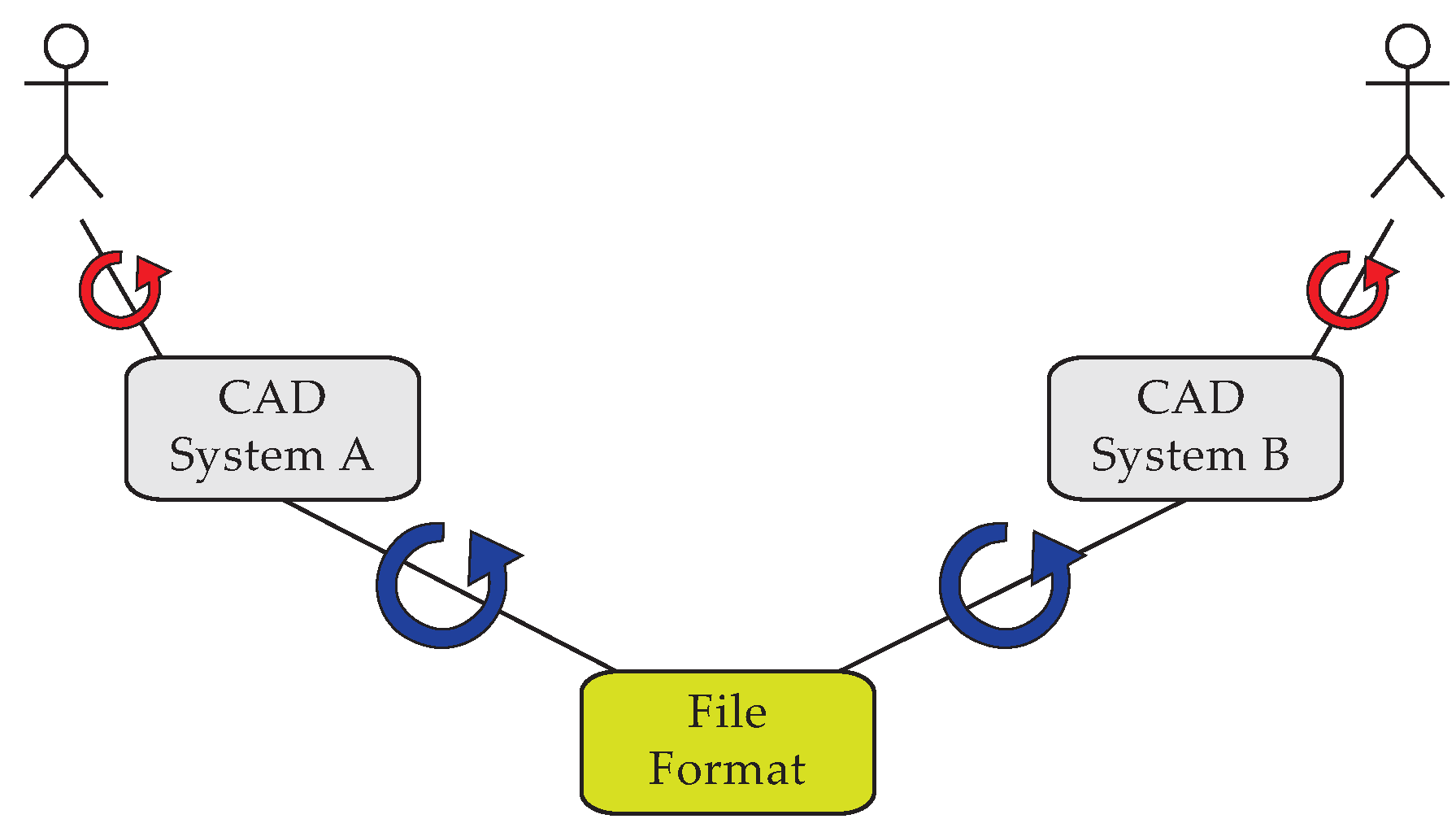
Figure 3, with every transition between two information systems consisting of at least two interface points between each of the information systems and one exchange file format. For example, the .DWG file format is an often used file format to communicate between diverse Autodesk modelling applications [
15]. In this situation, the interface points are materialised by the import and export functions of the applications at hand. Both the import and the export function constitute a mapping between the information structure of the application and the information structure of a certain file format.
Figure 3.
The information flow between two CAD systems using one file format contains two interface points (circular arrows) in which information needs to be converted, both between human users and information systems (in red) and among information systems (in blue).
Figure 3.
The information flow between two CAD systems using one file format contains two interface points (circular arrows) in which information needs to be converted, both between human users and information systems (in red) and among information systems (in blue).
Some file formats contain animation data, some describe building components, others are used for interactive web applications, and so forth. Because a different part of the AEC domain is described in each of these file formats, each file format tends to use a partly unique structure with an equally unique syntax and semantics, making it near to impossible to create a complete and exact mapping between an application and any of those file formats. Such import and export functions are used anyway, resulting in a loss of information. The lost information needs to be remodelled, leading further in the process to errors and limitations in the design conception stage and to inefficiency due to the required remodelling efforts [
16].
In some cases, additional conversions between file formats are needed, as is shown in
Figure 4. These additional conversions are either realised by a transition through another application, or by dedicated and freely available, but in many cases also incomplete, conversion tools. These tools do exactly the same as the import and export functions discussed before, namely mapping between diverse information structures, only in this case the mapping occurs between file formats only.
Figure 4.
The information flow between two CAD systems using multiple file formats contains multiple interface points (circular arrows) in which information needs to be converted, both between human users and information systems (in red) and among information systems (in blue). The number of interface points depends on the number of file formats used.
These extra conversion steps increase the number of interface points and thus result in a further loss of information, equally leading to errors and limitations in the design conception stage and to inefficiency due to the required remodelling efforts [
16]. Such extra conversion steps are typically used when an application cannot export to or import from a certain file format, most often because the application provides a notably different functionality. For example, the transition between a 3D modelling environment in architecture, such as AutoCAD [
15], and a game engine environment, such as Unity [
17], requires several file format transitions.
3.2. The Remodelling Effort
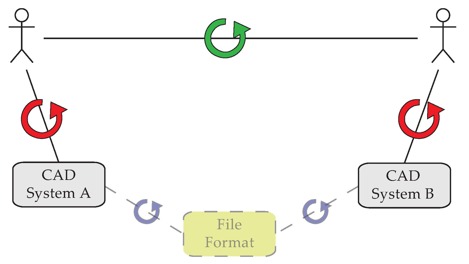
The remodelling effort strategy, which is schematically shown in
Figure 5, is a rather pragmatic and
ad hoc approach towards interoperability. Instead of trying to use file exchange mechanisms (conversion, import/export), which typically result in a certain loss of information, information is exchanged between the users themselves, who are in charge of their own versions of the design model.
Figure 5.
In the remodelling effort strategy, information is primarily exchanged between users, possibly with additional reliance on file exchange mechanisms. Interface points (circular arrows) are points where information is interpreted from one information structure into the other. In this case, this happens mainly among people (in green), but support via information systems is possible (red and blue interface points).
Nevertheless, this approach is often combined with the approach of sharing information in the wild (
Figure 2). As much information as possible is exchanged using traditional exchange tools, and information that is lost during this primary exchange is remodelled afterwards. However, manually remodelling information similarly results in a loss of information [
16], both in the communication between the human users and between the user and the application(s) in which the information is modelled. This remodelling approach does not address the issue of interoperability; it just puts the end user back in charge.
3.3. Kernel-Level Interoperability
Another approach, which is mainly suggested and used in the domain of 3D information exchange, is kernel-level interoperability. Most of the applications in the AEC domain rely on a 3D modelling kernel. As is indicated by Gerbino [
18], this kernel is responsible for storing and organising the basic geometric shapes and model topologies used by that application. Some well-known kernels used by CAD applications are ACIS (.SAT file format), Parasolid (.X_T file format) and Open Cascade (.CSFBD file format). A CAD application thus provides a whole range of functionalities that rely in their foundations on the functionalities offered by the kernel. By using a specific modelling kernel, a different representation of information can be provided as it might be required for specific design and analysis tasks. For example, a Computational Fluid Dynamics (CFD) application requires an entirely different geometrical representation than what is required in an application for mechanical product modelling. The CAD information structure might thus be considered as an extension of the more basic information structure of the 3D kernel. When two applications rely on the same kernel, they essentially have the same basis underneath their information structures.
Kernel-level interoperability relies on this common basis to optimise information exchange between these information systems. This approach might be of certain use in a pure 3D context. In such a context, it is advisable to exchange 3D information between applications with a common kernel in the file format of this kernel (.SAT, .X_T, .CSFBD). In this case, the 3D information is brought back into its basic form, making it understandable for the other application. In the other application, the 3D model can be reconstructed into its more advanced description. However, the original advanced description is not communicated, so there is a certain loss of information in the communication. The application into which the 3D model is imported, is supposed to reconstruct this advanced description from the kernel-level description solely. This approach might be feasible to some extent for pure 3D information, but it is highly unpredictable in an AEC project, because this project involves more detailed feature information, such as wall parameters, floor types and attributes, and so forth.
Furthermore, it does not work well between applications that use a different 3D modelling kernel, which is often the case in the AEC domain [
18]. In this case, kernel-level information exchange is just as reliable as any of the other file formats. In conclusion, this approach can merely be considered as a part of the approach of sharing information in the wild, which is shown in
Figure 2.
3.4. The Centralised Information Structure
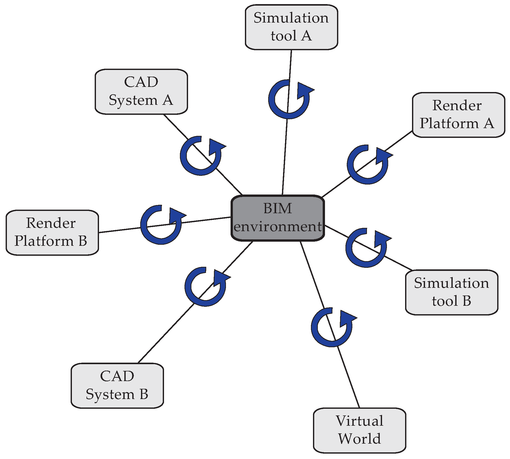
One of the latest approaches enjoying significant support in the AEC domain is the centralised BIM approach, in which one central 3D building model is used as a centralised information structure by several applications [
3] (
Figure 6). All information is stored in a central BIM model, which can be accessed from within diverse other applications in the AEC domain. Since all information is stored in one central model, all this information is always available for all users. Changes made to the design are applied to and stored in the BIM model, thereby making them directly available to other users.
Figure 6.
When relying on a centralised information structure, information exchange between information systems is based on a central building information model or BIM model. Of critical importance are the interface points among the BIM environment and the surrounding information systems (in blue), as these interface points dictate how information is passed and presented to the project partners.
Although this approach appears to eliminate some interface points, several such points persist in this approach (
Figure 6). These interface points are, however, seldom included in overviews of this BIM strategy [
19]. This gives the impression that information can perfectly be exchanged with any of the surrounding applications, which seldom happens efficiently in existing BIM applications [
20,
21,
22,
23,
24].
The schema in
Figure 6 appears to suggest that one can build a central information structure that is capable of describing all of the information possibly needed in any of the applications used in an AEC project. This suggestion is also made within diverse research initiatives towards a ‘standard’ or ‘neutral’ information structure for all building information [
4]. Examples of such suggested standards include not only proprietary industry standards, such as .DXF, .FBX, .IGES or .DWG, but also “neutral” formats, such as .STEP, .IGES, .X3D or .IFC. Over time, however, these standards merely tend to turn into yet another file format the user needs to convert information to or from, and the actual conversion issue is not solved. Both the results from the BIM approach and the results from the usage of standards [
20,
21,
22,
23,
24] indicate that it is not possible to rely on one central information structure that is capable of describing all building information. The centralised information structure as depicted in
Figure 6 is thus not feasible. In reality, the central information structure is just one of the many available information structures (
Figure 7).
Figure 7.
When relying on BIM software, “standard” file formats or any other centralised information structure, this structure is in reality just used as one of the many available information structures, with again lots of interface points (blue circular arrows) of which each represents an interpretation step between information structures.
3.5. The Software Suite Strategy
The software suite strategy might be considered as a mix of the kernel-level interoperability approach and the centralised information structure approach. In this strategy, a specific software suite from one product vendor is used by as much actors in the AEC project as possible (
Figure 8). An example is the Autodesk software suite, which includes applications such as AutoCAD, Revit and 3ds Max. This strategy assumes that the applications within this suite are all implemented using a similar 3D modelling kernel and similar top-level information structures. Because this results in better chances for understanding each other, this might be a practical approach towards addressing the interoperability challenge.
Figure 8.
The software suite strategy includes several “preferred” information flows, namely those between applications of the same software suite. Furthermore, these preferred information flows have interface points, but these interface points are supposedly implemented more easily as the different information structures are part of one and the same software suite.
On the other hand, this approach limits the user in choosing the appropriate application for the task. As soon as one wants to exchange information with information systems outside the product suite, the original interoperability challenge returns (
Figure 8). Additionally, even if one sticks to the information structure provided by the software suite, this approach is essentially identical to the first approach of sharing information in the wild (
Figure 2), but with a limited number of information structures.
3.6. The Linked Data Approach
A last promising approach is to separate the actual data from the applications they respectively reside in and to rely on a data representation in an open data format that is commonly agreed upon: the linked data approach. This approach has been suggested several times over history in diverse colours, forms and names. The Windows “Object Linking and Embedding” (OLE) technology, for instance, enables linking and embedding information from one application into the other, for instance, Microsoft Excel and Microsoft Word. By doing so, the information structures or object models of the information systems are linked on the data level, as is shown in
Figure 9, making the information sharable between the applications. As soon as one wants to use this information in an application outside this web of linked data, however, the situation is back to what it was before: not interoperable. This approach thus works more or less like the software suite strategy depicted in
Figure 8, only implemented more on a data level.
Figure 9.
In the linked data approach, information is linked on the data level. This results in a web of linked data that is accessible for any application that wants to use it. Furthermore, the interface points between information systems (blue circular arrows) are now to be implemented on the data level.
More recent examples in which this linked data approach is implemented, can be found in the semantic web domain [
5]. Using semantic web technologies, one is able to describe information in a directed labelled graph using a common data model: the Resource Description Framework (RDF - Manola and Miller [
25]). Continuously extending this directed labelled graph results in a globally interconnected semantic web, or a linked data cloud [
6,
8], which is directly connected to the ontologies or description structures structuring its information. As such, these technologies allow one to combine information models used in diverse information systems, with respect for the inherent semantics and syntax of each of these partial graphs (
Figure 9).
A semantic web approach has been suggested a couple of times to improve the interoperability of CAD information, for instance by Abdul-Ghafour
et al. [
26]. The authors indicate how semantic web technologies allow the combination of information from several different knowledge domains, enabling a seamless coupling of 3D information with non-geometric information, such as design intent and domain-specific product features. Similar suggested approaches relying on semantic modelling of product information, not necessarily targeting improvements regarding the interoperability issue, can be found in Kraft and Nagl [
27], Abdul-Ghafour
et al. [
28], Böhms
et al. [
29,
30], Yang and Zhang [
31]. Pauwels
et al. [
32] similarly presents how semantic web technologies enable the integration of architectural design information with general AEC and 3D information available through the IFC schema, whereas Pauwels
et al. [
33] considers the usage of rules and reasoning engines for the proper exchange of 3D information itself.
Two important reasons why this approach might be better compared to the other approaches, is: (1) that semantic web technologies rely on a common language for describing information, namely the Resource Description Framework (RDF - Manola and Miller [
25]); and (2) that semantic web technologies appear to be deployed on a global scale [
6,
8]. As a result of the second element (global scale use), information that would typically be unavailable in the software suite strategy (
Figure 8) has a notably higher chance of being readily available in the linked data approach, making this currently one of the most promising approaches for information exchange and management among information systems. Of course, there are reasons why semantic web technologies are so appealing that they are used on a global scale by very diverse domains of application. Of considerable importance for this appeal is the reliance on a very simple and open representation structure (triples with an object - predicate - subject structure). Because of the simplicity of the representation structure, all possible kinds of information can be represented, including 3D data and metrics. So, the range of the RDF data model is not confined to a particular domain. Additionally, all data that is represented in RDF has a truly unique resource identifier (URI), making all data typically globally unique. Third, the RDF data model has a strong logical basis, which allows the usage of reasoning engines and the availability of inference. These elements are a strong basis for information exchange, resulting in the global use of these technologies. As this global usage further extends the set of data and tools that can be reused, it makes even more sense to use these technologies for information exchange, increasing the global usage even further, and so forth.
4. Functionality Mismatch between Information Systems and End Users
As indicated before, there is a second element in the central issue of information flow, apart from the information flow among information systems. Namely, there is also a mismatch between the functionality provided by information systems and the functionality expected by end users (see
Figure 1). Functionality provided by modelling applications is either “not enough and too simple” or “too much and too complex”. The functionality provided by simulation applications is “not correct” or “irrelevant”. The visualisation produced by visualisation applications “does not communicate the required information”. Additionally, archive applications typically contain only the information one “does not need”. It might be argued that many of these functionality mismatches arise from using software for purposes for which it was not meant to be used. In the case of construction industry, however, there just are a high number of people involved, each having a considerable number of purposes throughout the course of a construction project. With this context in mind, many of the applications in the construction industry are rather generic and present a wide range of information to an equally wide range of end user profiles. As a result, these applications typically provide functionality that just misses what is required by the user profile requesting information.
Therefore, in any case, addressing this issue is not just a technological issue, it is a matter of capturing what is required by specific end users and customising the application performance and functionality towards that requirement. In others words, the process should drive the application and actively demand from the application to represent information from particular sources to be presented in a particular custom view.
As the current paper is less focused at the non-technological issues, we will look below at the more technological issues underlying the above aim to let an application be driven by the end user’s needs. More precisely, we will look at the parallel between the functionality mismatch issue and the lacking interoperability among information systems, and we will look into some improvements to the functionality mismatch issue that might result from the suggested linked data approach.
4.1. The Parallel with the Lack of Interoperability
In a lot of practical scenarios, the information presented by the system does not conform to the needs and/or desires of the end user. It is as if two different information models or semantic domains are maintained, by the human user and by the information system, and both models do not match. As well in the mind of the architectural designer as in the information structure of the information system, an information model is maintained for the design situation at hand. The resulting functionality, which is in more concrete terms human interaction and output from the information system, respectively, is based on these mismatching information models. In many cases, the underlying information model is notably different, and because this information model lies at the basis of the provided functionality, also, the resulting functionality is different.
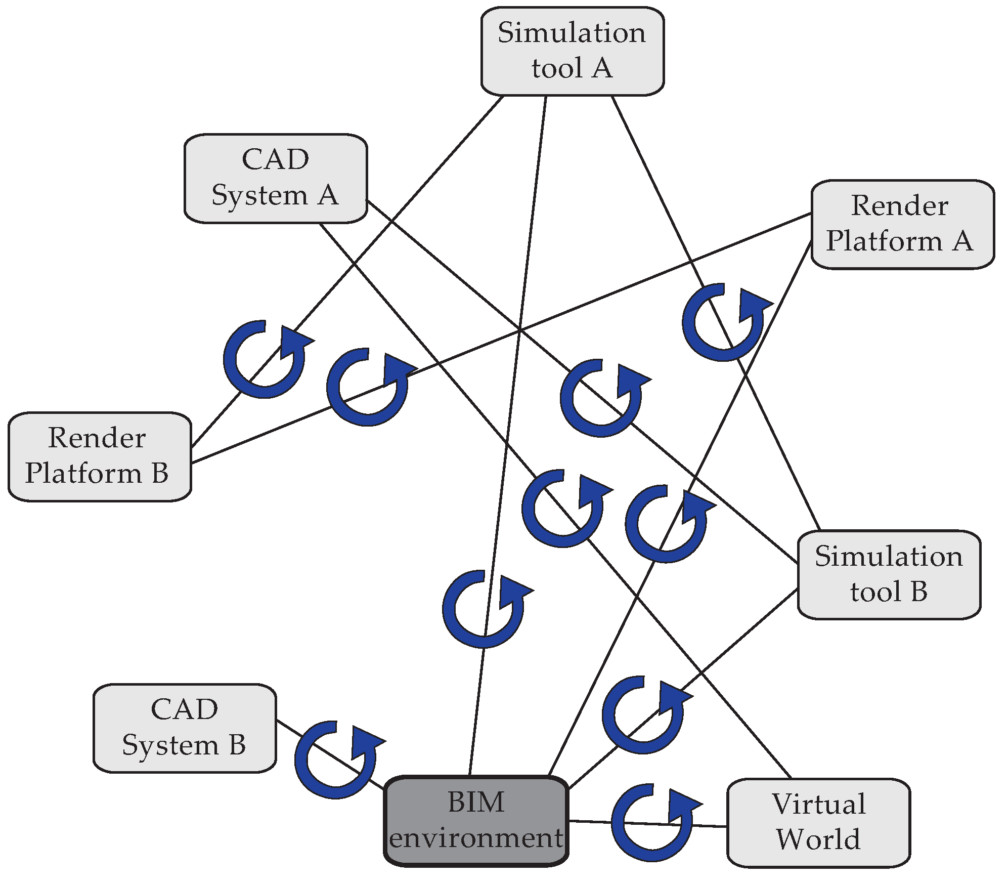
Clear examples supporting this argument can be found in the interaction between designers and modelling applications (AutoCAD, SketchUp, 3ds Max, Rhinoceros,
etc.). Each modelling application provides a specific functionality to the designer and relies on an application-specific information model to achieve this specific functionality. We have seen how this results in problems when information is to be exchanged between these modelling applications (indicated in blue in
Figure 10). However, a designer similarly relies on a certain understanding of a design situation, which might be simplified and represented as an information model of its own. This information model in the designer’s mind differs at least as much from the information model in the modelling application. For instance, certain architects mainly understand the design of a building in terms of historical references and architectural theories. These concepts are seldom included in modelling applications, such as the typical 2D CAD environments, resulting in a mismatch of functionality. Whereas the designer wants to model the design in terms of historical references and architectural theories, the modelling application only allows one to use simple lines and points. Additionally, even when similar concepts appear to be present in the application and in the mind of the designer, these concepts often have different connotations in both contexts. For example, the representation of the material construction for a wall object can be interpreted in various ways. Whereas an architect may want to know what these materials look like and how they should be represented in the various plan views, structural engineers may want to know their load capacities, HVAC engineers may require their thermal conductivities, and so forth.
An example was previously discussed in Pauwels
et al. [
9], concerning the construction of the Port House in Antwerp, Belgium. In this project, the Port House was modelled using Autodesk Revit Architecture. However, many of the elements that needed to be modelled did not match the standard set of available objects and concepts in Revit (windows, walls,
etc.). In this case, compromises needed to be made by the engineering team in function of the desired end product, and a pragmatic modelling approach was followed.
Figure 10.
The issue of information flow, as outlined in
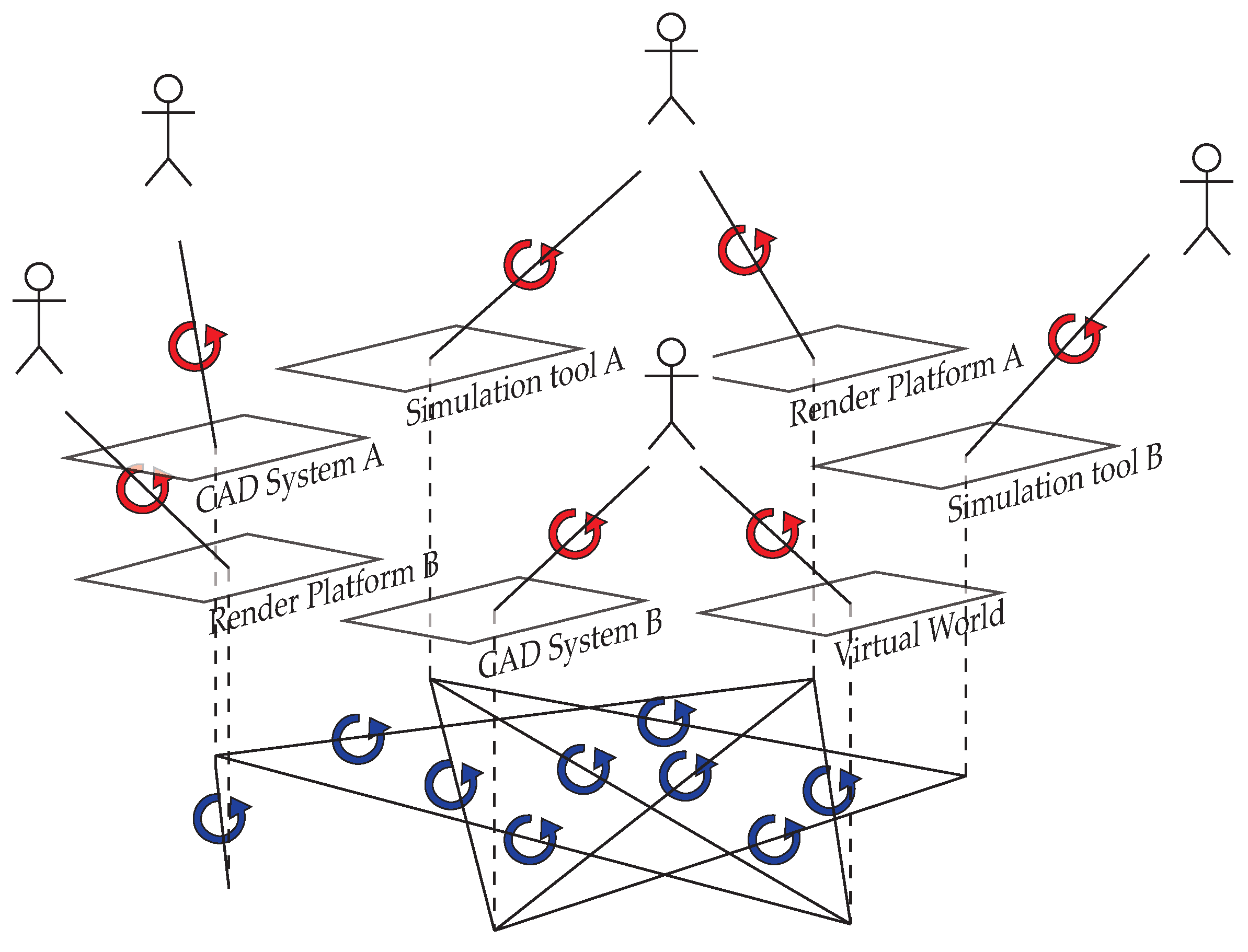
Figure 1, can be subdivided in an interoperability issue among information systems (bottom - blue circular arrows) and a functionality mismatch issue between information systems and users (top - red circular arrows and user icons). The former issue is caused by interface points between information systems (blue circular arrows), whereas the latter is caused by interface points between information system and end user (red circular arrows). The information systems themselves are static environments displayed in the middle of the Figure (rectangular shapes).
Figure 10.
The issue of information flow, as outlined in
Figure 1, can be subdivided in an interoperability issue among information systems (bottom - blue circular arrows) and a functionality mismatch issue between information systems and users (top - red circular arrows and user icons). The former issue is caused by interface points between information systems (blue circular arrows), whereas the latter is caused by interface points between information system and end user (red circular arrows). The information systems themselves are static environments displayed in the middle of the Figure (rectangular shapes).
4.2. Improvements Anticipated in a Linked Data Approach
The linked data approach might also result in improvements for the functionality mismatch issue. Namely, the linked data approach might enable architectural designers to model their understanding of a design situation independent of the information models available in the applications that they use. The resulting information model is then accessible to applications, which can use these information models to provide the functionality required by the end user.
We will briefly look into the “CultureSampo” project as an example project in the domain of cultural heritage [
34,
35,
36,
37]. This project similarly relies on a linked data approach with semantic web technologies for combining diverse information models. It additionally provides diverse services and applications on top of this information, each time using a specific part of the information. Similar to the AEC domain, the cultural heritage domain also encompasses very diverse kinds of information, as is illustrated by Mäkelä
et al. [
34]. One and the same element, e.g., the person “Gallen-Kallela” in Mäkelä
et al. [
34], can be considered from very diverse perspectives, similar to the way in which a design situation or a building can be considered from very diverse perspectives. Typically, each perspective is described in a bounded environment. In the case of Gallen-Kallela, these bounded environments are distinct databases, each managed by a different institute. In the CultureSampo project, these databases were integrated using semantic web technologies, resulting in a graph that combines the available information models (
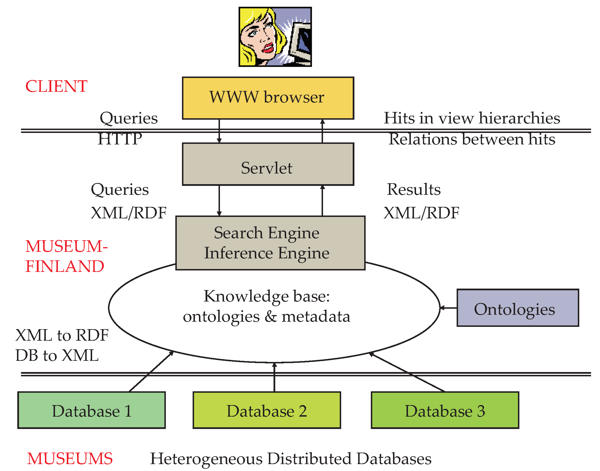
Figure 9). The resulting “knowledge base” is then accessible from within various applications, among which is a WWW browser, as indicated in
Figure 11. As such, information is integrated from over thirty organisations [
34].
Figure 11.
Architecture of the semantic portal “MuseumFinland” as shown in Hyvönen
et al. [
35]. Local database contents are merged and made available for query access, which can be used by diverse applications and users. Reproduced from Hyvönen
et al. [
35]. Copyright 2005 Elsevier.
Figure 11.
Architecture of the semantic portal “MuseumFinland” as shown in Hyvönen
et al. [
35]. Local database contents are merged and made available for query access, which can be used by diverse applications and users. Reproduced from Hyvönen
et al. [
35]. Copyright 2005 Elsevier.
Therefore, diverse information models are combined in a linked data approach, and diverse user interfaces are presented to the end user, each time presenting specific information tailored to the requirements of the end user. Examples of generated user interfaces can be found in Mäkelä
et al. [
34]. This includes visualisations of selected cultural heritage artifacts in a time line interface or a geographical map interface, for instance. However, also very specific interfaces can be generated. For instance, an information model was added that allows the representation of historical areas related to their borders and their artifacts [
34]. An interactive interface can be built on top of this information, allowing exploration by the end user. Mäkelä
et al. [
34] similarly indicates how the “knowledge base” in
Figure 11 was extended with additional related information models by the BookSampo project [
38]. This project includes information models about Finnish fiction literature and links this to content in the CultureSampo knowledge base. Information is thus reused in different contexts by different users using different functionality.
5. Towards a Web of Linked Building Data
When using a linked data approach, a considerable number of technologies are available that are an inherent part of the set of semantic web technologies. Information resources are represented with the RDF data model and identified with Unique Resource Identifiers (URIs) [
25]. The Web Ontology Language (OWL) enables the representation of ontologies or vocabularies that can be used for structuring RDF graphs [
39]. The Simple Protocol and RDF Query Language (SPARQL) allows querying the RDF graphs [
40]. Reasoning engines allow the inference of extra information. With these possibilities, semantic web technologies and the resulting LOD cloud can be considered a useful set of technologies for addressing the initial research question that is considered in this article. They apparently promise to connect various information resources on a global scale and make the result easily available to various services and application types [
41,
42].
5.1. Integration within the Construction Project
One can easily start from the IFC schema [
4] to set up a linked data approach for the AEC domain. The IFC schema is a neutral and standard schema for information exchange among BIM environments. This information schema is currently one of the best means currently available and used to address interoperability issues in the AEC sector. Using the IFC schema, one should be able to represent a BIM model so that other applications are able to use this information as well, for instance, for simulation and visualisation purposes.
An IFC-to-RDF conversion service is available that converts IFC information into an RDF representation [
41]. Implementing this IFC-to-RDF conversion service is not a straight-forward process, because diverse mapping schemas are typically available for mapping between an IFC file and an RDF graph, or between an IFC schema in EXPRESS [
43] and an IFC ontology in OWL. Especially the more advanced features of the EXPRESS schema of IFC, such as rule functionality and cardinality restrictions, can be translated into diverse RDF constructs. A comparison of the three conversion procedures used in Pauwels and van Deursen [
41],Beetz
et al. [
44], Törmä
et al. [
45] illustrates this situation. One might thus conclude that a “perfect conversion procedure” does not exist for converting IFC information into RDF representations. Rather, there exist various “flavours” of conversion procedures, each resulting in a specific kind of RDF representation. One conversion procedure might result in a simple, compact and straight-forward RDF graph; a second procedure might result in a complete, but impractical RDF graph; and yet another procedure might provide an RDF graph fit for specific reasoning purposes, for instance.
Assuming that similar RDF conversion services can be implemented for other (neutral or proprietary) schemas typically deployed in an AEC context, such as the file types .DWG, .RVT, .DGN, .gbXML, and so forth, one can easily imagine diverse information models available as RDF graphs within the same building project (
Figure 12). By relying on linked data principles and techniques, these information models, which can be considered separate “silos of information” [
46], might well be linked together, resulting in a linked data cloud for each AEC project. Direct links are thus available among simulation information, CAD information, architectural information, visualisation information, and so forth. A distinction can be made between links among models, indicated with dashed arrowed lines in
Figure 12, and links among model entities, indicated with full arrowed lines in
Figure 12 (see also Törmä
et al. [
45]).
When considering the schematically proposed linked data approach shown in
Figure 12, however, one has to seriously keep in mind our earlier remark regarding the diverse flavours of conversion procedures. There are diverse conversion routines possible in each step from an AEC application (outer circle in
Figure 12) towards the linked data cloud for an AEC project (inner circle in
Figure 12). One can easily understand the resulting information management difficulties by considering:
the number of (proprietary and non-proprietary) schemas available in the AEC domain (IFC, DWG, RVT, DGN, gbXML, and so forth);
the number of conversion routines between schemas and OWL ontologies, and between information models and RDF graphs;
the number of linking possibilities between two RDF models (dashed and full arrowed lines in
Figure 12).
Figure 12.
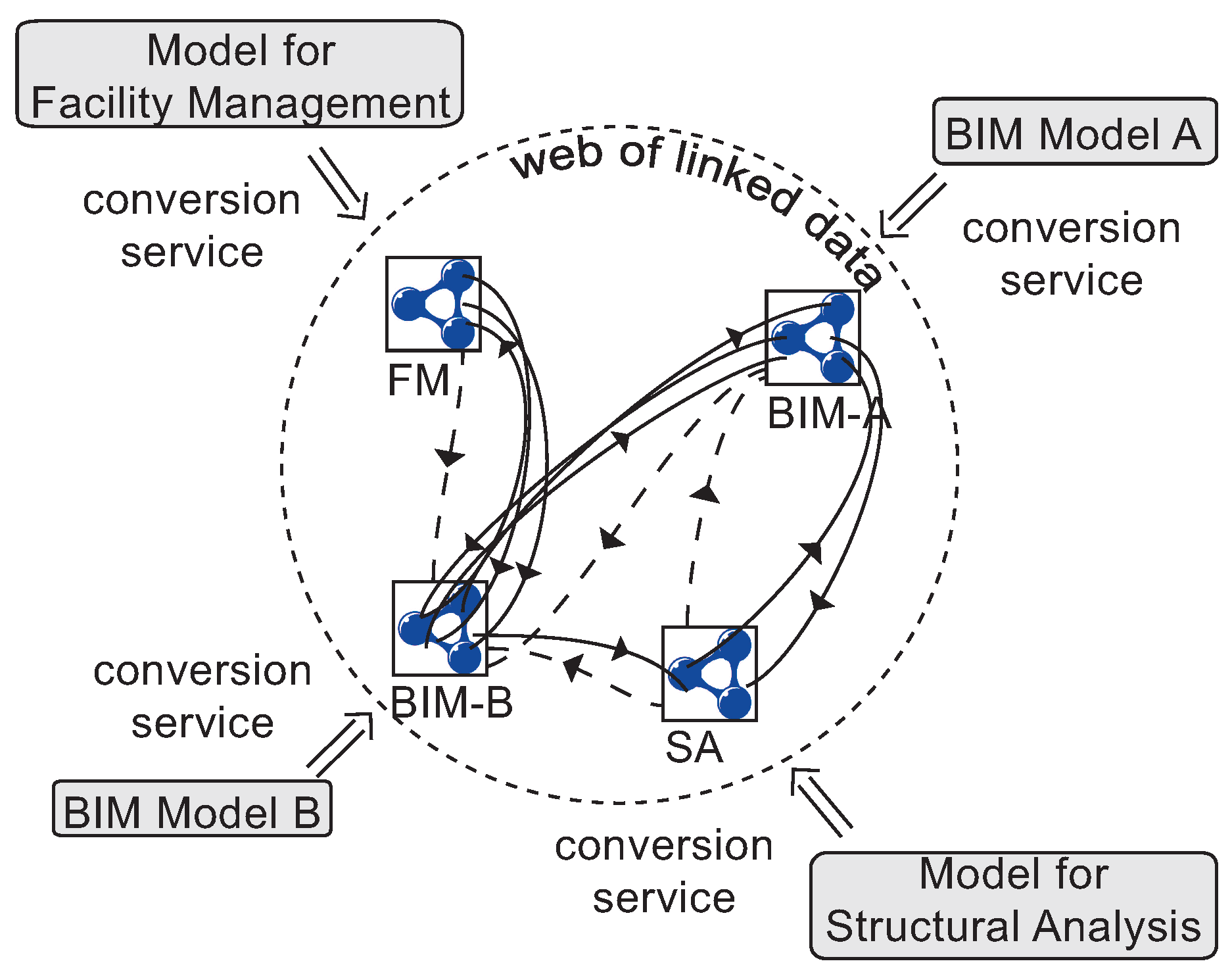
Diverse conversion services might enable to make diverse partial information models (BIM Model A, Model for Facility Management; BIM Model B, Model for Structural Analysis) available in Resource Description Framework (RDF) graphs. The conversion steps are indicated in the figure as arrows going in one direction from the native format (outer circle) towards the RDF graph format (icons in inner circle). The resulting graphs might then be linked in a “web of linked data” using semantic web technologies (dashed and full arrowed lines).
Figure 12.
Diverse conversion services might enable to make diverse partial information models (BIM Model A, Model for Facility Management; BIM Model B, Model for Structural Analysis) available in Resource Description Framework (RDF) graphs. The conversion steps are indicated in the figure as arrows going in one direction from the native format (outer circle) towards the RDF graph format (icons in inner circle). The resulting graphs might then be linked in a “web of linked data” using semantic web technologies (dashed and full arrowed lines).
Therefore, difficulties that are related to the interoperability issue will to some extent remain present in the suggested linked data approach. Nevertheless, the suggested approach presumably will generate improvements regarding the interoperability issue in the sense that better means are available in addressing this issue.
5.2. Integration outside the Construction Project
Semantic web technologies additionally allow one to link the linked data clouds of AEC projects (
Figure 12) to information outside the construction project (schematic links to geographical and product information in
Figure 13). As such, external information may be deployed for specific purposes in an AEC project. This includes annotations, documents, project management tools, geographical information, demographic information, and so forth. With this information, more advanced services and applications may be targeted, in which diverse resources of information are combined [
46]. For example, an outline of cost efficiency statistics related to usage statistics of a building might bring about significant new insights to the building owner.
Note that, also in this context, the same difficulties need to be taken into account regarding the management of mapping and linking procedures among information models. This can be related to the difficulties outlined in the semantic web domain regarding the usage of the owl:sameAs construct [
47]. Although it might be valid in one context to link entities in different information models or application domains, these links might not be equally obvious or valid in other contexts.
Figure 13.
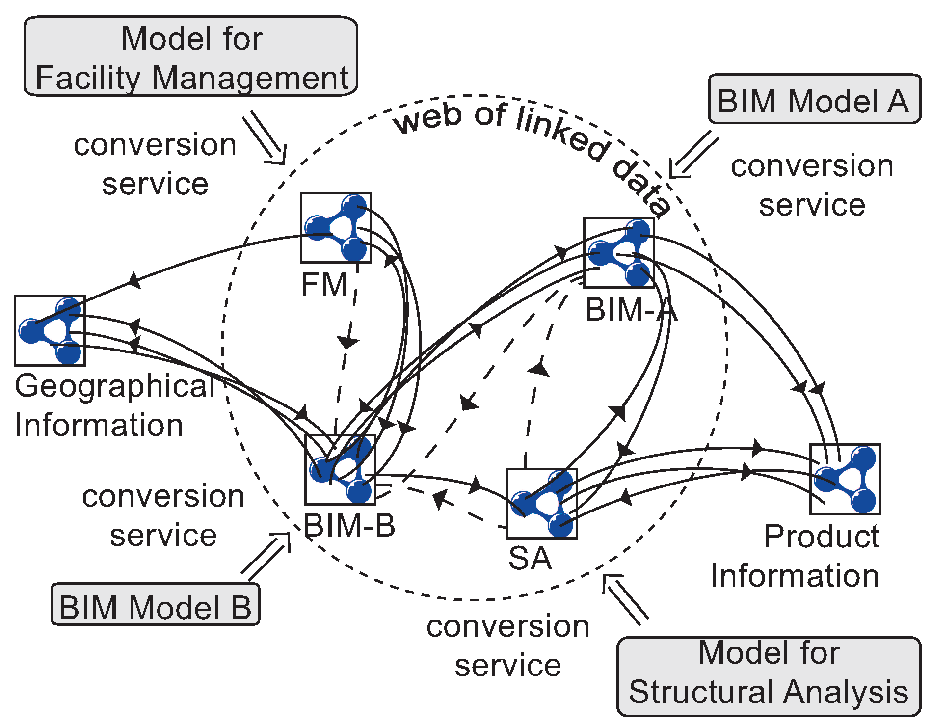
The linked data cloud for the AEC project can be further enriched with additional links to external resources of information (geographical information, product information, and so forth).
Figure 13.
The linked data cloud for the AEC project can be further enriched with additional links to external resources of information (geographical information, product information, and so forth).
6. Challenges in Terms of Information Exchange and Management in a Linked Building Data Approach
As any other approach or strategy, the linked building data approach has its limitations and challenges as well. When particularly considering the topic of interoperability, challenges reside mainly in the creation and management of the links between diverse information models in RDF. This question has been dealt with before in the AEC domain, although not relying on semantic web technologies (nor RDF). For example, the usage was suggested of “view models” that are integrated or that communicate through a “model kernel”, which is formed by the overlapping of the view models [
48]. Alternatively, the suggestion was made to use “views” as “functional contexts” for the diverse partners or disciplines in an AEC project [
49]. These views can then be linked by the addition of explicit relations. An implementation with relational database technologies was furthermore suggested in Rosenman and Gero [
49]. Using Model View Definitions (MVDs - Hietanen [
50]) in combination with an Information Delivery Manual (IDM - ISO [
51]) is a more recent variant for these suggestions: different model views are defined in MVDs, each model view representing a partial view of the complete information model for the AEC project; the IDM keeps track of how, when and where such model views should be exchanged among partners in the project (see also Berard and Karlshoej [
52]).
These and other approaches have thus been suggested for dealing with the creation and integration of partial models. Initiatives that tend to fail are initiatives in which the original information is converted or translated into an alternative information schema, often combined with discarding the original information or with cutting the static or dynamic links to the original information. In these cases, a valuable amount of information is lost. Approaches that appear to have higher chances to succeed are approaches that enable users not only to create partial models, but also to maintain the original format and preferably also the link between the partial model and the related information model(s). In these cases, the partial model is provided to interested third parties, but the original information is kept intact. Crucial in this approach is to maintain the link or the mapping schema between the original partial model and the related partial model, whether this model be a follow-up model (sequential) or an alternative model (parallel).
Of course, such an approach will surely require a setup of open and proprietary BIM servers or of linked building information servers that provide more than the typical BIM servers. These servers have important requirements regarding dynamic change management and the associated notions of security and privacy. In the following subsections, we look into the diverse considerations that have to be made in realising the latter approach for AEC information in a linked data context with semantic web technologies. We make a distinction between technical considerations, practical considerations, usability considerations and maintenance and management considerations.
6.1. Usability Considerations
Information in an AEC project is always represented by a specific partner in the building life-cycle. Not only is this partner supposed to be qualified for representing this information, this partner is typically also considered responsible and representative for this information. This is important information that should be taken into account when giving access to the information that is represented by this partner, not only for reasons of rights and ownership, but also for reasons of representativeness, trustworthiness and usability. To what extent is the represented information correct and trustworthy, and to what extent can it consequently be used? This consideration relates to the issue of information scope management that is outlined in Törmä
et al. [
45].
In a linked building data approach, each partial model or RDF graph represents a different model view that is maintained and used in the building life-cycle. Each of these partial models has its creator, who is considered representative for the information in the partial model. Reference to this creator is not only available in the URIs used for representing the entities in the partial model, but should also be available in metadata that is associated with the partial model. Both the URIs and the metadata allow other end users to check the trustworthiness and usability of the information. In this approach, anyone can provide information, and certain information becomes more or less trustworthy depending on the number of similar assertions and the status or expertise of the partner that has provided the information.
6.2. Practical Considerations
Second, each of the partial models available in the building life-cycle is typically produced by one specific party, for instance one of the many architectural design firms, and with one specific design tool, for instance one of the many CAD modelling applications. These partial models implicitly include the original schema and understanding of the representation, both in terms of the design situation (specific people and context) and the used design tool (specific information structure). In other words, a different partial model will result, depending on the application that is being used for modelling and the modelling techniques of the end user.
When developing linked data environments for accommodating such partial models, this context needs to be taken into account, because it has a considerable impact on the system. For instance, information within one and the same partial model reflects the information from one specific subdomain in the AEC project and is thus typically more coherent and more closely related. Links among entities within this partial model can be made with less effort. Links among different partial models, for instance a structural model and a client requirements model for the building, are harder to realise. The system thus, for instance, needs to take into account that considerably more links are available within one and the same partial model and less are available among diverse partial models.
Additionally, within this context of partial models with each its own information structure and its own context, it makes sense to allow building all partial models within their specific environments (modelling applications, simulation applications, visualisation applications, and so forth) and link them together only at a read-only level (see also Törmä
et al. [
45] and
Figure 12). As a result, only one conversion service is needed instead of a round-trip through two conversion services. If one would want to integrate all information once and for all into one complete all-containing model, which we do not suggest here, proper conversion round-trips would be necessary.
When linking diverse partial models into a linked data cloud for an AEC project, the following link types are some of the link types that can be considered:
links between partial models
- (1)
sequential links
- (2)
parallel links
links between entities of a partial model
- (1)
links among objects
- (2)
links between objects and requirements (design brief, urban regulations, …)
- (3)
links between objects and activities (acts of construction, supply, maintenance, …)
- (4)
links between objects and documentation (specifications, maintenance records, …)
- (5)
links between objects and people (construction workers, asset allocation and ownership, …)
- (6)
links between people and activities (scheduling of use, scheduling of maintenance, construction scheduling, …)
- (7)
and so forth
6.3. Technical Considerations
Considerable technical considerations were also outlined in Törmä
et al. [
45] regarding the generation of links among and within the diverse information models. It seems infeasible to rely on either automatic or manual methods. A semi-automatic method thus seems most promising. In such a method, an initial set of links is generated among (entities of) the considered information models, after which the generated links are returned to the end user for further modifications. The usage of clash detection and link discovery software could be considered as aids in the link generation process [
45].
One needs to take into account that, after generating links among and within models, these links should be easily maintained and managed. How this maintenance and management of links can be realised, is handled in the following subsection, which briefly deals with change discovery and change propagation. It should be enough to note here that a practical and realistic change discovery and change propagation relies on the availability of persistent and unique identifiers for the many available entities represented in the RDF graphs (see also Törmä
et al. [
45]). In this regard, we initially suggest using the following procedure for generating links among and within the information models. For each step, we indicate how it could be implemented when relying on semantic web technologies.
- (1)
Identify the IDs:
Upon conversion from the initial software environment into an RDF graph, the diverse IDs that are used in the original software environment are retrieved, so that the diverse entities and concepts in the RDF graph can be given unique URIs that relate to the IDs in the original software environment. By doing so, future changes to the partial model can be propagated into the linked building data graph. We suggest to rely first and foremost on the globally unique identifiers (GUIDs) that are being used by the diverse software applications producing the partial models. These GUIDs are to be converted into URIs, taking additionally into account information about corresponding owner, project and partial models. This could thus result in the following URI design for entities in the partial information models:
http://owner.country/project/partialmodel/guid.
- (2)
Link the IDs among and within models:
When the URIs of the entities in the diverse partial models (as RDF graphs) are available, (entities within) the partial models can be linked in a semi-automatic manner using the outlined link types (between partial models and/or between model entities). The generated links are encoded as additional RDF statements. When one of the linked partial models is modified, a reasonable decision should be made by the partners who are in charge of the partial models about whether or not to maintain or modify the specific links between the entities or the modified models.
- (3)
Add more information:
Further information can be added to the diverse partial models, with the information coming from various domains of practice, also outside the AEC domain. The existing LOD cloud [
8] provides an important available resource from and to which to make such links. Adding this information can be done by simply adding additional RDF statements.
- (4)
Provide an interface to access links:
The information models, the entities in the information models and the links among both should finally be made available to the end users who have the appropriate access rights. This can be done by publishing the complete graph in an online RDF store with an appropriately accessible SPARQL endpoint. Using the metadata that is added to the partial models for information scope management, an appropriate user interface with the appropriate levels of security and rights administration can be implemented on top of this SPARQL endpoint, giving partners in the AEC project access to the information for which they have access rights.
6.4. Maintenance and Management Considerations
A realistic maintenance and management of the generated linked building data for the AEC project requires important considerations in terms of change discovery and change propagation. We suggested earlier to initially rely on an approach in which existing software (e.g., BIM software, simulation software, and so forth) is used by partners in an AEC project to build partial models, after which these partial models are exported into RDF graphs (see also
Figure 12). The conversion of GUIDs into URIs, which is central in the presented procedure for generating links among models and entities in those models, should allow to appropriately update/replace the available RDF graphs with the newly exported partial models.
The most important issue then becomes the maintenance and management of the links that were previously made among (entities in) the partial models that are being replaced. Whether these links be stored internal or external to the models they belong to, one does not want to end up with hanging, missing or wrong links. Note that a change in one of the partial models can propagate all the way up to the final construction plan, so this is a crucial part of realising a linked data system that gives support within the building life-cycle.
The three following strategies can be outlined regarding link change management:
Reactive change propagation across models:
The other parties are notified about a change so that they can restore the consistency.
Proactive change protocols:
Collaborative protocols are used that enable taking into account the views of different parties affected by a change. There are different possible protocols based on change proposals, counterproposals, and so on.
Transactional change management protocols:
Protocols are used that take the advantage of the distributed versioning capabilities of the participating models.
7. Anticipated Use Cases in the Building Life-Cycle Context
We finally want to anticipate some example use cases in the building life-cycle in which the usage of a linked data approach, as briefly sketched above, might provide additional benefits to the diverse stakeholders in the building life-cycle. These use cases focus on building optimisation, information management and support for the design and construction process. Central in these use cases is the idea that a linked data approach has the possibility to enable a more holistic view on information about the building, as well in the design and construction phase as in the maintenance phase.
7.1. Design and Construction Phase
The resulting improvements to information management are a key reason for adopting a linked data approach in the AEC domain. Consequently, main use cases in which improvements can be expected are situated in the design and construction phases of AEC projects. In this context, the most important improvement is expected to be generated by the change management features of the suggested approach. Namely, assuming that appropriate links can be made among and within diverse partial models stemming from diverse partners in the building life-cycle, and assuming that the appropriate metadata is added in this process, the system can presumably give better indications of how changes in a certain partial model affect the linked partial models. These indications can be used by that specific partner in the AEC project to make better informed decisions. By using a linked data approach, more partial models can be reached than is traditionally the case, because of the ease of linking diverse partial models in an RDF graph. A more holistic view of the AEC project is thus obtained than is traditionally the case.
A concrete use case that is anticipated here focuses on energy performance and usage evaluation in the design and construction phase. In this case, three partial models are combined into one RDF graph (
Figure 14). The first partial model represents the building using the terms of a specifically devised space topology vocabulary. We could in this case rely on the room vocabulary ontology that was devised by Richard Cyganiak (Digital Enterprise Research Institute, NUI Galway - DERI) and that is available at Cyganiak [
53].
Figure 14.
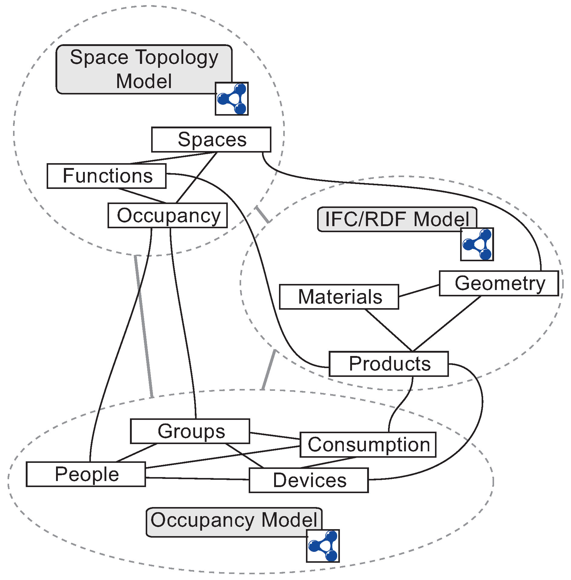
A combination of three partial models for a use case in performance evaluation in the design and construction phase.
Figure 14.
A combination of three partial models for a use case in performance evaluation in the design and construction phase.
The second partial model, that should be closely linked to the first partial model, represents the building using the terms available in the IFC ontology, including geometric properties of the building and, to some extent, product information. It would presumably be a good test for the change propagation and change discovery features of the system to see to what extent changes in the IFC/RDF model of the building can be propagated into the space topology model (
Figure 14).
A third partial model finally represents people, groups, devices and energy consumption using the terms available in the the Friend of a Friend (FOAF) ontology [
54] and the DERI Energy ontology [
55]. By linking this third partial model to the two other partial models, one can test to what extent the links between these models can inform the designer or construction firm about the energy performance effects that are inferred by certain changes in the space topology, the product choices or the building geometry, for instance. Alternatively, it might be possible to make strategic choices in the occupancy model and see if and how one should change the room topology or building geometry to accommodate the desired performance level.
7.2. Maintenance Phase
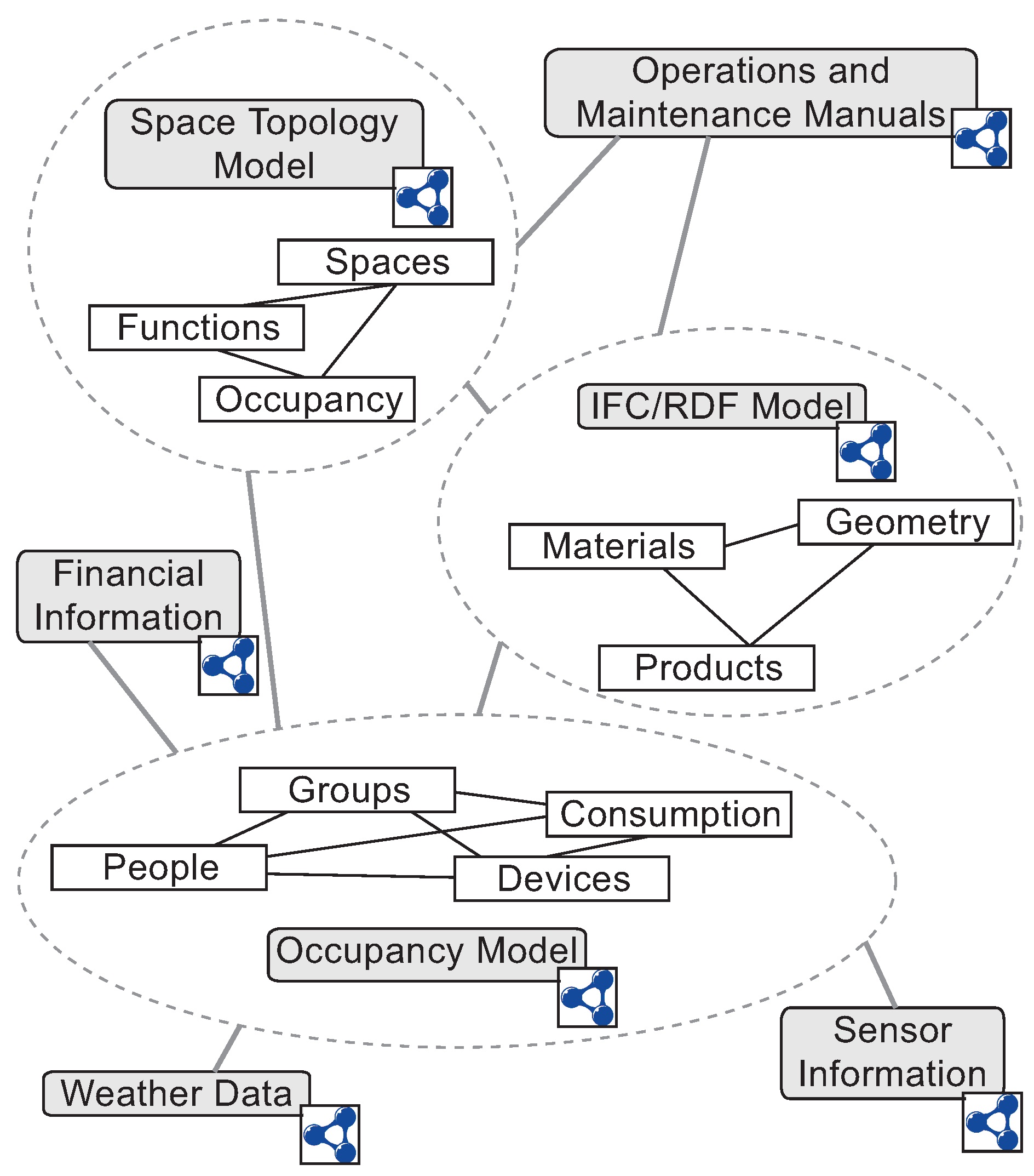
A second use case focuses on the maintenance phase of the building. The use case that is anticipated here literally extends the first use case, in the sense that additional partial models are added upon completion of the building that take into account sensor information, operations and maintenance manuals, financial information, weather data, and so forth (
Figure 15).
Figure 15.
Extending the linked building data cloud for the AEC project with links to sensor information, operations and maintenance manuals, financial information and weather data should allow improving building performance in the maintenance phase of the building life-cycle.
Figure 15.
Extending the linked building data cloud for the AEC project with links to sensor information, operations and maintenance manuals, financial information and weather data should allow improving building performance in the maintenance phase of the building life-cycle.
By making links among these partial models, one can perform very specific queries over the merged graph, thereby enabling a better informed or more holistic view on the overall performance level and the usage of the building. Such a use case was already started in the context of an exploratory test of the possibilities of a linked data approach for building energy intelligence [
46]. In this work, the diverse partial models that were available in the building maintenance phase were regarded as separate silos of information. The silos of information considered are a traditional building energy performance (BEP) silo, an architectural silo, a human resources silo, a legislation silo and an inventory silo. By combining the information in these silos for a particular energy zone (total building energy consumption, energy consumption for Research Group 1, cost of utilities for Research Group 1 and associated carbon dioxide emissions for Research Group 1), a real-time impression is given to the building manager about the building use and potential requirements for building maintenance that he did not have before. These real-time indicators are presented to the building manager in a format that can be used by him to manage this particular site. As such, this use case not only indicates how the linked data approach can combine different available partial models (interoperability), but also how they can be presented, so that they are usable to particular end users, in this case, BEP modelers, the human resources team and the building maintenance manager.
Although this was not indicated in the use case presented by O’Donnell
et al. [
46], the linked data approach can also accommodate versioning in the building data. In some cases, especially in the context of building maintenance, it might be necessary to combine live and historical data of the same building, so that a building manager or owner can check both how a piece of equipment was functioning previously and how it is functioning currently. By allowing one to make that comparison, one might be able to determine when and why it has started malfunctioning. This can be accommodated in the linked data approach by using the possibility to add multiple models (of the same building) and link them together using sequential model type links. Depending on the goal, entity type links might be added, as well. The sequential link then indicates that one model is a follow-up model, in chronological order, of a previous model, so that a maintenance analysis over time can be done following these sequential links.
8. Conclusions
In this article, we have investigated to what extent linked data technologies might be able to address the long-standing interoperability challenge in the AEC domain. Applications in the AEC domain often provide only limited support to partners in a design and construction project, due to a malfunctioning information flow. This malfunctioning information flow can be subdivided into two main issues: a lack of interoperability among information systems and a functionality mismatch between information systems and end users (
Figure 10). Notwithstanding the significant amount of effort put into the design and implementation of applications for the AEC domain, these issues return time and again in the evaluation of software usage in the AEC domain.
We have looked into strategies for addressing the interoperability issue, resulting in a brief discussion of the following strategies:
Sharing information in the wild;
The remodelling effort;
Kernel-level interoperability;
The centralised information structure;
The software suite strategy;
The linked data approach.
The linked data approach is suggested as one of the most promising strategies for addressing interoperability issues, mainly because: (1) these technologies rely on a common language based on a logical foundation for describing information; and (2) these technologies appear to be deployed on a global scale. The latter reason is important, because, no matter how standard or efficient a language might be, it needs to be used by information systems to enable information exchange among this group of information systems. The larger the group of information systems using a language, the more information systems can exchange information. From a conceptual point of view, significant improvements can be made regarding the management and usage of information in AEC projects by relying on a linked data approach. The main anticipated improvement is situated in the context of the interoperability of information in the AEC domain. However, because of the sheer amount of information available in the linked open data (LOD) cloud, also a more holistic view on the information of the building can be made available to end users in the building life-cycle, thereby enabling them to make better informed decisions.
An indication is given of how information in AEC projects can be integrated using a linked data approach. However, significant considerations and challenges are outlined, as well, more particularly regarding the creation and management of the links within and among the diverse (partial) information models represented in the linked building data cloud. This involves usability considerations, practical considerations, technical considerations and maintenance and management considerations. It appears that linked data technologies will not “solve” interoperability issues, but that they will at least allow one to address some of the prevailing issues in terms of information exchange in general. Especially when effectively combined with other information exchange mechanisms, such as the centralized BIM approach and the IFC-MVD-IDM technologies, they can significantly improve information exchange in the AEC domain. This article has finally given an initial outline of possible use cases in the design and construction phase and in the maintenance phase of an AEC project.
