2.2.2. Parametric Model
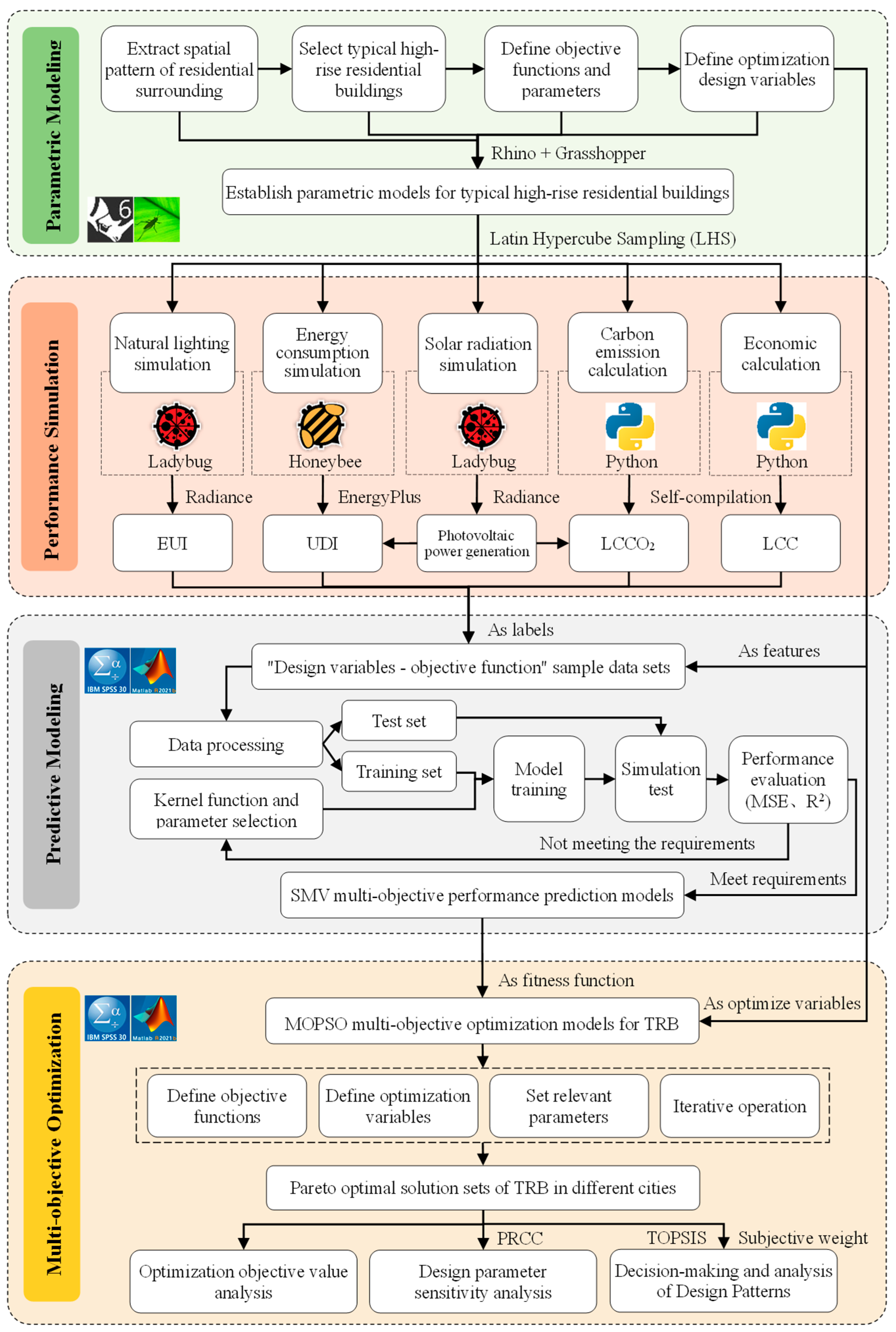
To ensure the representativeness of the established model, a survey was first conducted in high-rise residential areas across three cities. The survey contents cover morphological design parameters such as the land area and layout form of residential areas, building height etc., as well as unit type design parameters including floor plan layout, areas, and dimensions etc., and the building envelope construction. Newly built high-rise residential buildings constructed over the past five years (from 2019 to 2023) were selected, and a combination of online and on-site investigation methods was adopted. For the online survey, Gaode Map and the National Geographic Information Public Service Platform (Tian map) were used as the primary data sources, with Tencent Map and Baidu Map serving as supplementary data sources. The on-site investigation was carried out by contacting the property department of the residential areas to obtain design drawings and relevant data. Finally, data were collected for 62 high-rise residential areas (including 821 high-rise residences) and 284 unit types. Through statistical analysis of residential area form (land area, floor area ratio, layout form, and building height), unit type attributes (plan layout, area, and dimensions) and enclosure structures (exterior wall, roof, and windows), the spatial form and design features of typical high-rise residences were extracted, thus identifying several typical spatial patterns. Taking one typical pattern as an example, parametric models were established using the Rhino–Grasshopper platform, which serve as the foundation for subsequent building performance simulation and optimization.
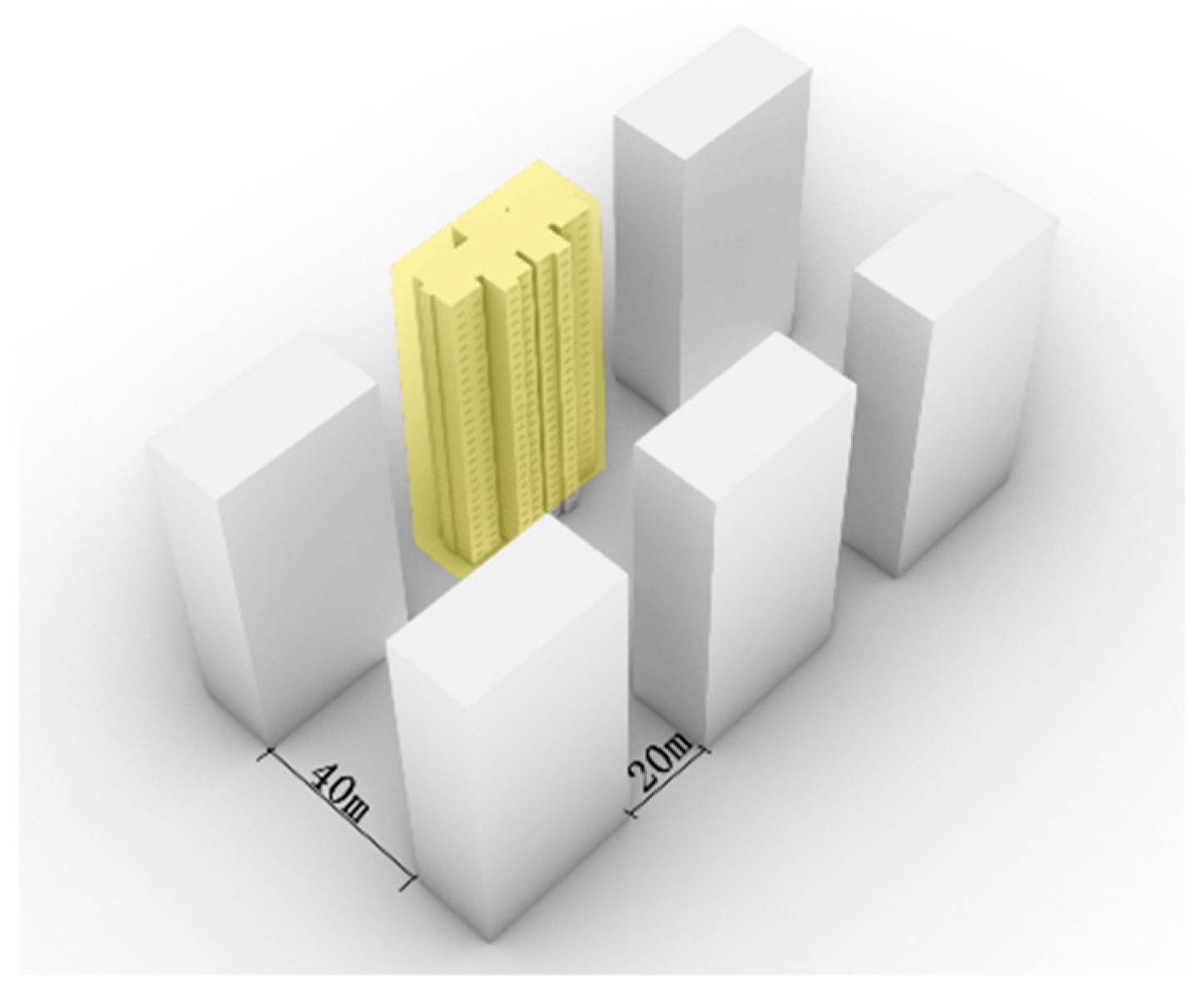
High-rise residences are usually presented in a cluster layout form. Surrounding buildings can affect sunlight access, natural lighting, etc. Therefore, the surrounding spatial patterns of high-rise residences were first analyzed and extracted. According to the analysis of land use scale and floor area ratio of high-rise residential area, a parallel layout consisting of six buildings arranged in two rows and three columns is adopted, as illustrated in
Figure 5. The high-rise residence (yellow blocks) located at the most disadvantageous position is selected as the research object to ensure the resulting design scheme has broader applicability. Combined with the building spacing requirements for residential buildings specified in “GB 50180-2018 Standard for Urban Residential Area Planning and Design” [
50], and through sunlight simulation analysis, the north–south spacing is determined to be 40 m, with the east–west spacing set at 20 m. In line with the survey results, the high-rise residences are defined as 26-story buildings with a south-facing orientation.
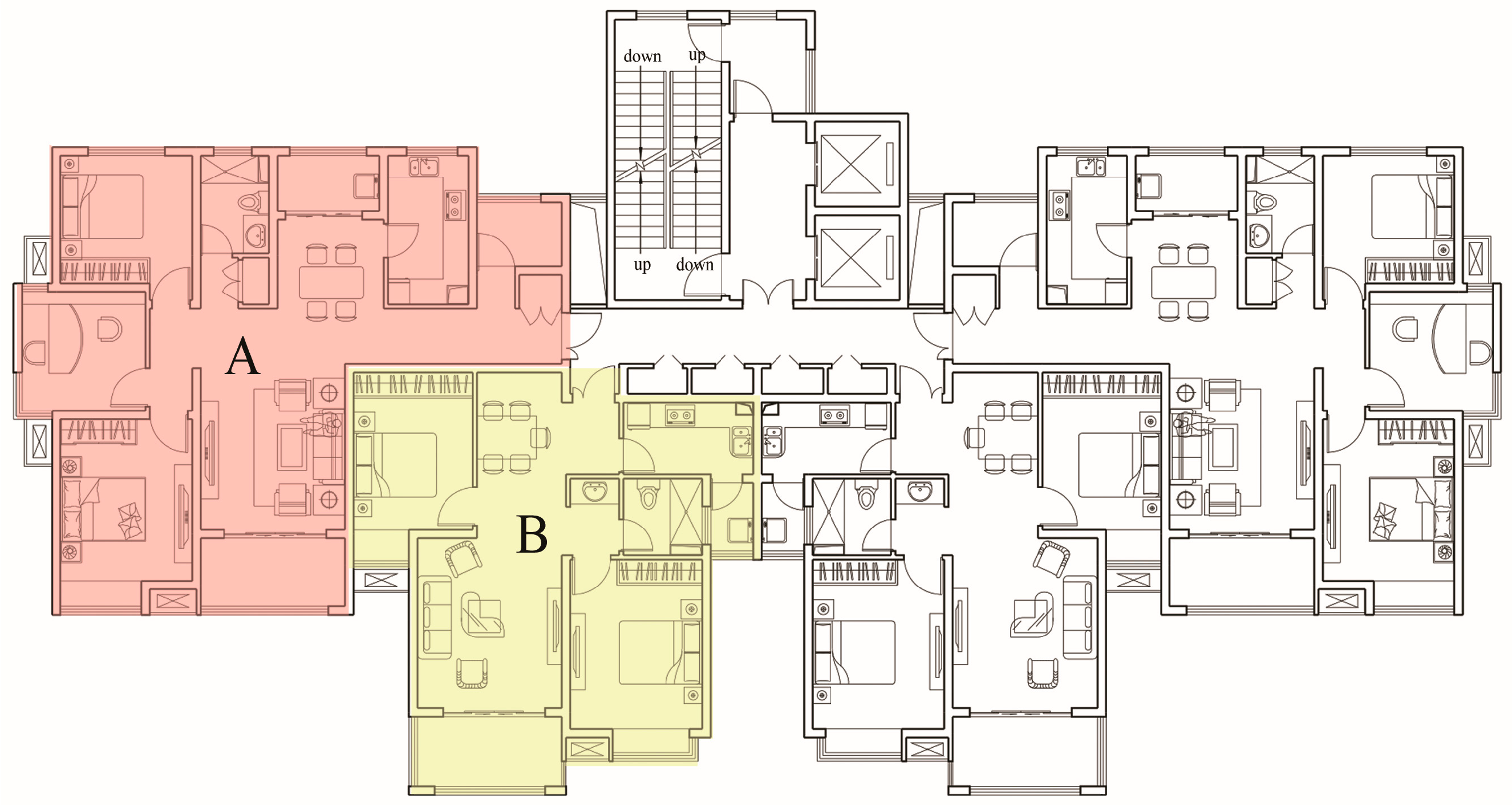
For single-building high-rise residence, the two-elevator, four-unit layout is the predominant floor plan form, accounting for 85% of the survey samples. Accordingly, this layout is designated as the typical floor plan configuration for high-rise residences, with the standard floor plan shown in
Figure 6, where it integrates a three-bedroom, two-living room layout with a two-bedroom, two-living room layout. The specific design parameters are presented in
Table 2, the building envelope construction and heat transfer coefficients are detailed in
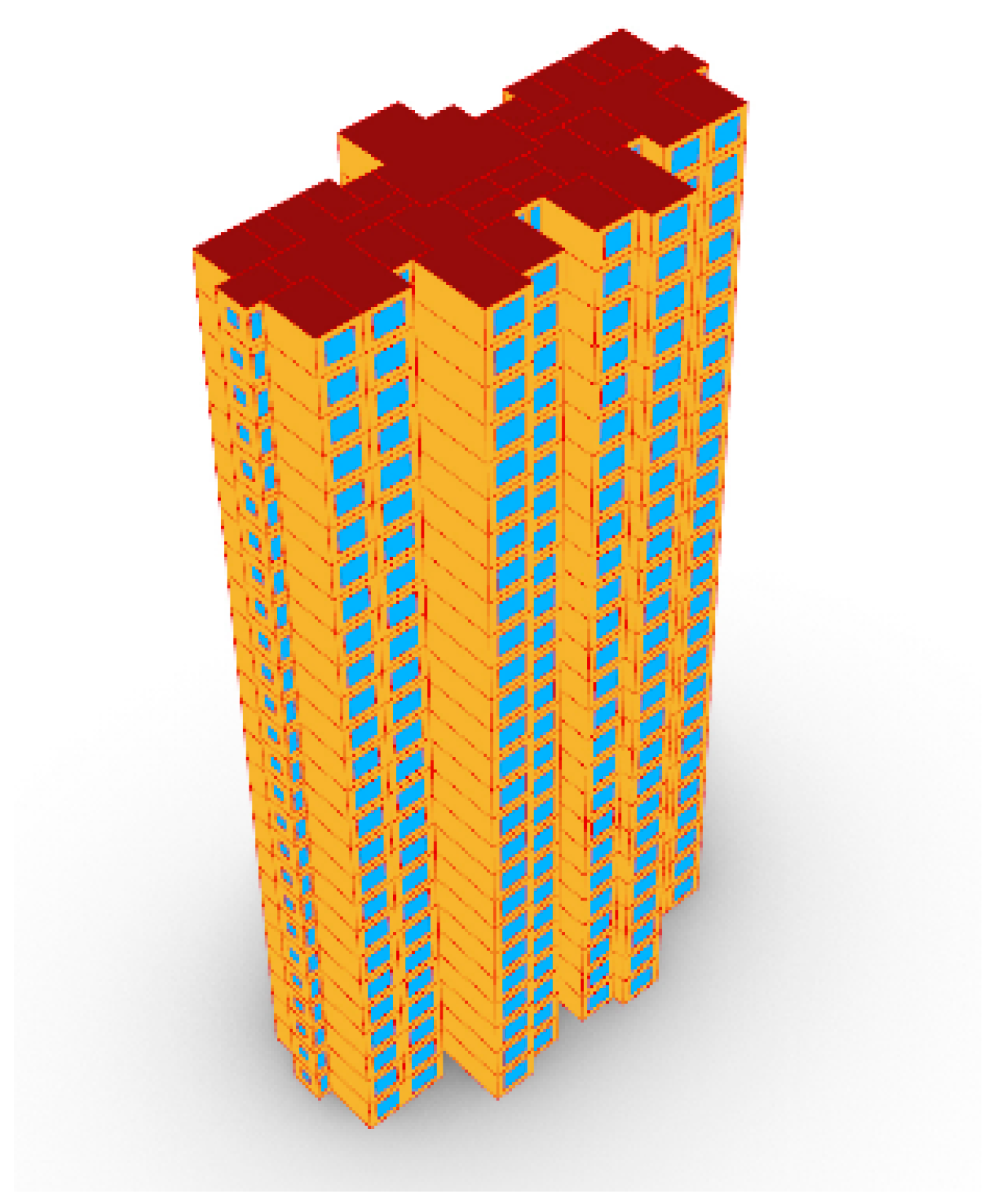
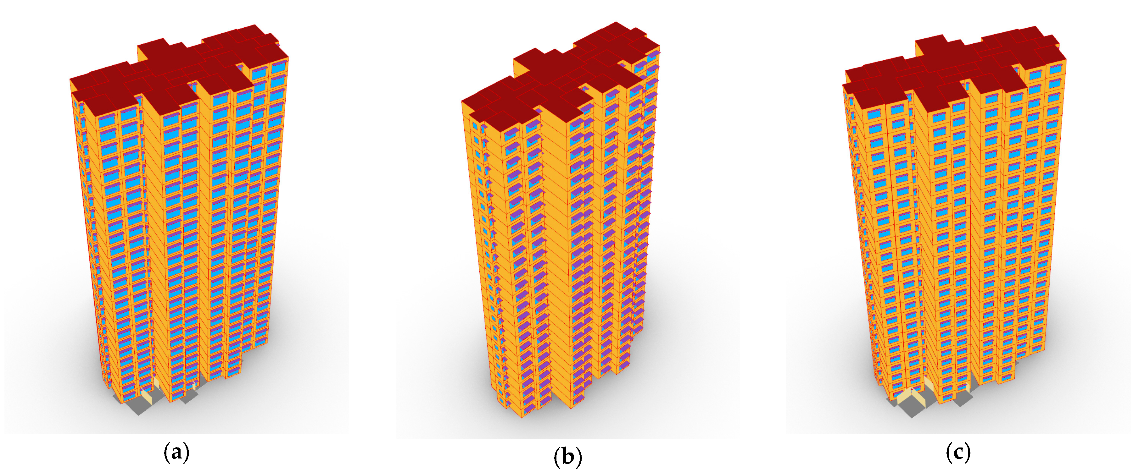
Table 3, and the parametric model is depicted in
Figure 7.
The installation of solar photovoltaic systems in high-rise residences should comply with the provisions of “CECS 418: 2015 Technical specification for integration of building and solar photovoltaic system”. The installation location must ensure that there is more than 3 h of sunlight throughout the day on the winter solstice [
51]. By simulating solar radiation on building facades with different orientations, and ensuring an effective comparison of BEI across three cities, the following uniform settings are adopted: photovoltaic panels are installed on building rooftops and the south-facing exterior wall surfaces above the 16th floor (excluding window areas). Rooftop photovoltaic panels are mounted at a 30° inclination angle, while wall-mounted panels are installed vertically.
2.2.3. Objective Function
This section defines the calculation methods for four optimization objectives (building energy consumption intensity, useful daylight illuminance, life cycle carbon emissions, and life cycle cost), converting these objectives into quantifiable objective functions to ensure the accuracy of performance evaluation in the subsequent optimization process.
- (1)
Building energy consumption intensity (BEI)
Operational energy consumption refers to the external energy introduced during a building’s service life, encompassing energy expended on maintaining the building’s environment (e.g., heating, cooling, and lighting) and that consumed by various in-building activities, such as the operation of electrical appliances and the preparation of domestic hot water. Relevant studies have indicated that operational energy consumption accounts for over 80% of a building’s life cycle energy use [
52], with heating and cooling energy consumption constituting the largest proportion. This paper focuses on the scheme design phase, emphasizing the energy consumption of building itself in maintaining its environment, excluding energy used for electrical appliances, domestic hot water, etc., where energy consumption for heating and cooling account for the dominant share.
China’s national standard “GB 55015-2021 General code for energy efficiency and renewable energy application in buildings” [
4] stipulates that new buildings shall be equipped with solar energy systems to improve energy efficiency. Owing to their height advantage, high-rise residences are more suitable for photovoltaic systems, which helps to enhance the utilization rate of renewable energy. Therefore, photovoltaic systems should be incorporated into the building design stage. In accordance with the provisions of “GB/T 51366-2019 Standard for building carbon emission calculation” [
53], the annual electricity output of a photovoltaic system can be calculated using Equation (13).
Therein, Epv is the yearly electricity output of photovoltaic system, kWh; I is the yearly solar irradiance on the surface of photovoltaic cells, kWh·m−2; KE is the energy conversion rate of photovoltaic cell, taken as 15%; KS is the efficiency loss of photovoltaic system, taken as 25%; and Ap is the net surface area of photovoltaic modules, m2.
This paper designates building energy intensity (BEI) as one of the optimization objectives, defined as the annual energy consumption per unit of building floor area. It is calculated by subtracting the annual electricity generation of photovoltaic system from the total annual building energy consumption, where the latter can be extracted from the output results of the EnergyPlus simulation engine. The method used to calculate BEI is illustrated in Equation (14).
Therein, BEI is the building energy consumption intensity, kWh·m
−2;
A is the building area, m
2;
EH is the heating energy consumption, kWh;
ηH is the heating system efficiency, taken as 0.8 [
18];
EC is the cooling energy consumption, kWh;
ηC is the cooling system efficiency, taken as 3.0 [
54];
EL is the lighting energy consumption, kWh; and
Epv is the yearly power output of photovoltaic systems, kWh.
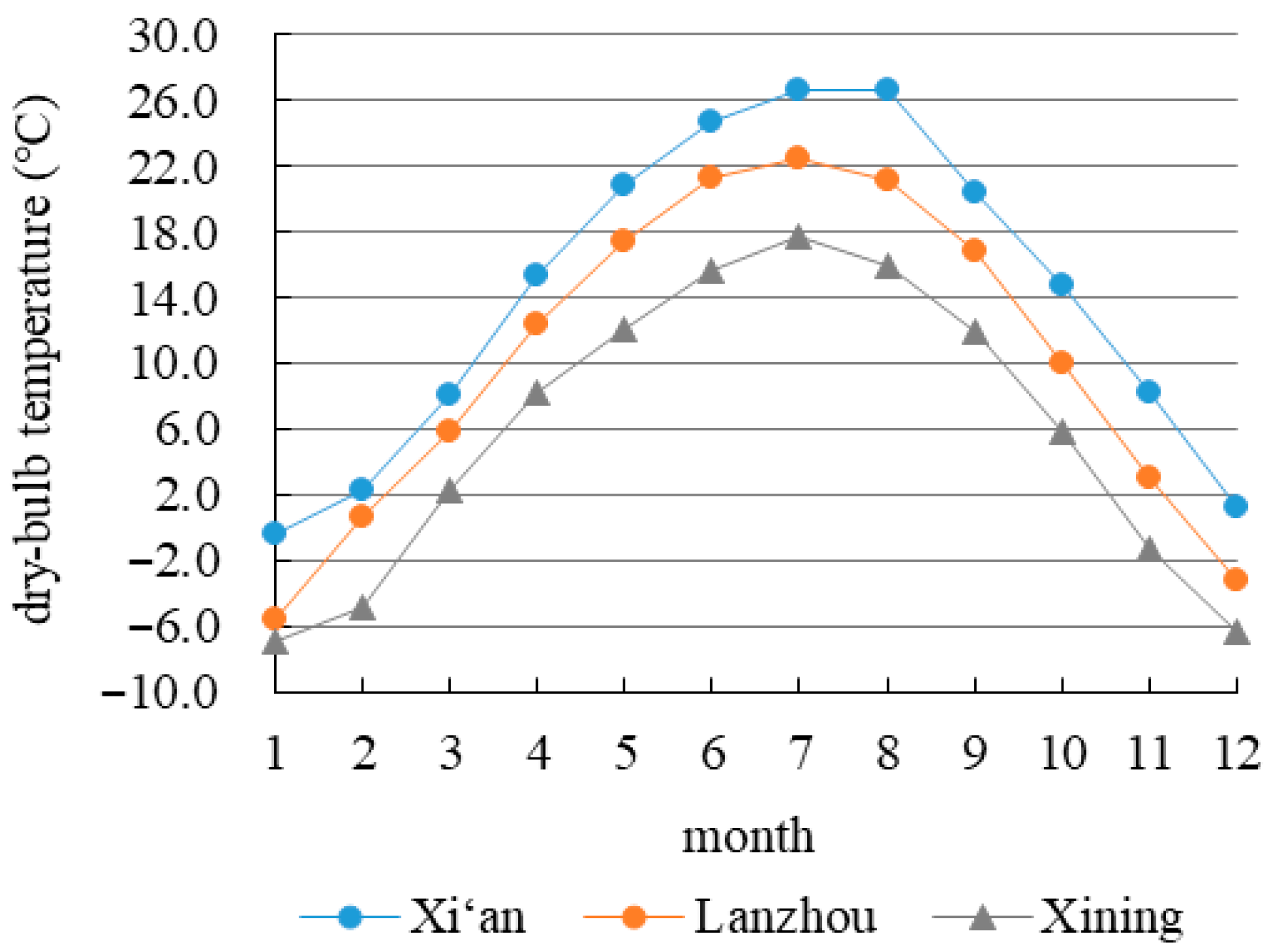
The parameters related to energy consumption simulation are specified as follows: the heating period in Xi’an spans from 15 November through to 15 March of the next year; in Lanzhou, it runs from 1 November to 31 March; and in Xining, it extends from 15 October to 15 April. The indoor heating and cooling set temperatures are 18 °C and 26 °C, respectively. Bedrooms, living rooms, kitchens, and bathrooms are designated as heating and air conditioning zones, while other auxiliary rooms are classified as non-heating and non-air conditioning zones. The heating system operates 24 h a day. The cooling demands in the three cities are mainly concentrated in the summer. The cooling period is set from 15 June to 15 September, and the air conditioning system is set to the ideal mode. Relevant studies have shown that different control strategies can affect the simulation results of building energy consumption [
55]. To accurately reflect real-world usage scenarios and achieve better energy-saving effects, a natural ventilation control method is utilized to optimize the operation time of the air conditioning system. That is, based on the set cooling temperature, window opening and air conditioning system activation are controlled by comparing indoor and outdoor temperatures. The control strategy is shown in
Table 4.
The occupancy rate, lighting, and electrical equipment usage time are set according to the recommended values in the energy-saving design specifications [
4]: the occupancy density is 0.25 people/m
2, the lighting power density is specified as 5.0 W/m
2, the power density of electrical devices is configured to be 3.8 W/m
2, and the rate of air exchange is set as 0.5 h
−1.
- (2)
Useful daylight illuminance (UDI)
UDI is adopted as the evaluation index for the daylighting performance. This index was first proposed by Nabil and Mardaljevic in 2005 [
56], and is used to assess the effective utilization of natural daylight in building spaces, as it accounts for both excessively high and low illuminance levels. The illuminance level is divided into three intervals: below 100 lx, between 100 lx and 2000 lx, and above 2000 lx, while considering the visual comfort at each level. When indoor illuminance is less than 100 lx, basic visual needs cannot be met, and artificial lighting is therefore required to ensure the basic space lighting requirements. When illuminance exceeds 2000 lx, glare may occur, leading to visual discomfort. In this case, shading measures or adjusting to exterior window design should be implemented to reduce illuminance value and improve visual comfort [
57]. It is more appropriate to maintain the illuminance between 100 lx and 2000 lx. This not only meets lighting requirements but also avoids increased lighting energy consumption and visual discomfort.
Therefore, taking UDI
100~2000 lx as the optimization objective, the higher the value, the better the lighting performance. The UDI calculation for a single measurement point is shown in Equation (15). The UDI of the entire building is the arithmetic mean of all measurement points.
Therein, UDI100~2000 lx is the useful daylight illuminance at one measurement point, %; TUDI is the number of hours in a year when the natural lighting is between 100 and 2000 lx, hours.
Using the Honeybee plugin in Rhino–Grasshopper platform, and invoking the Daysim and Radiance simulation engines, an hourly daylighting performance simulation was conducted, with directly output of UDI
100~2000 lx value. Lighting grid points were divided at a spacing of 0.5 m, and the working surface height was defined as a horizontal plane 0.75 m above the ground. The optical parameters of the building envelope and materials were set in accordance with the “GB 50033-2013 Standard for Daylighting Design of Buildings” [
58], as follows: the reflectivity of exterior walls and roofs was 0.32; the interior walls and ceilings were painted with white plaster, with a reflectivity of 0.75; the floor adopted light-colored wooden flooring, with a reflectivity of 0.58; the shading panel has a reflectivity of 0.2; and the roughness of all materials was set to 0.05. The visible light transmittance of exterior window was set according to the window types.
- (3)
Life cycle carbon emission (LCCO2)
LCCO
2 is mainly used to assess carbon dioxide emissions generated by buildings throughout all phases of the life cycle [
59]. Research indicates that carbon emissions from building operation, as well as the production and transportation of materials, account for approximately 90% of total LCCO
2 [
60,
61]. Therefore, in this paper, the scope of LCCO
2 is confined to emissions produced during material production and building operation stages, excluding the construction and demolition stages. In addition, since this optimization design does not involve any changes in the materials transportation, emissions associated with this stage are not included in the calculation. China’s national standard “GB/T 51366-2019 Standard for building carbon emission calculation” [
53] stipulates the use of carbon emission factors (CEF) for calculating building carbon emissions. As high-rise residences are equipped with photovoltaic systems, the carbon reduction achieved through photovoltaic power generation must be incorporated into the calculation. To more intuitively demonstrate the differences between schemes and the carbon reduction potential of optimized schemes, domestic hot water systems and carbon sinks, etc., are not included in the calculation. This study adopts a 30-year life cycle period. It is assumed that insulation materials, windows, and shading devices, etc., will not be replaced during this period; hence, the carbon emissions generated during materials production are calculated on a one-time basis.
The calculation method of LCCO
2 is shown in Equation (16). Among them, carbon emissions during the operation stage mainly originate from building energy consumption. The intensity values of heating, cooling, and lighting energy consumption need to be converted into energy values with the same unit as the supplied energy, and then multiplied by the corresponding energy carbon emission factors [
62].
Therein, LCCO
2 is the carbon emissions per unit building area over the life cycle, kgCO
2·m
−2;
i refers to the building materials;
Qi is the quantity of
i;
fi is the carbon emission factor of
I;
n is the life cycle years, set as 30;
H is the conversion coefficient between thermal energy and coal, kWh·(kg)
−1, set as 8.14 [
63];
fc is the carbon emission factor of coal, kgCO
2·(kg)
−1, set as 2.77 [
53]; and
fe is the carbon emission factor of local power grid, kgCO
2·(kWh)
−1, set as 0.6671 [
53].
- (4)
Life cycle cost (LCC)
LCC analysis is a method for evaluating the economic benefits associated with project costs, and serves as a key indicator for measuring the economic feasibility of design schemes. It enables a comprehensive assessment of design decisions from the perspective of long-term economic efficiency [
22,
64]. According to the international standard ISO 15686-5: 2017 [
65], the life cycle cost includes design and construction costs, operation costs, maintenance costs, and dismantling costs. The life cycle is also set at 30 years, with the assumption that the building envelope and components do not require replacement or maintenance during this period. In terms of investment cost, given that the main structures, labor costs, and transportation costs are largely identical across different design schemes, there is no need to calculate the absolute value of the initial investment cost. Only the incremental cost resulting from changes in design parameters need to be calculated. Therefore, the LCC in this paper contains the additional cost of the optimized design and the energy cost during operation (including the cost of energy savings from photovoltaic system). The calculation method is shown in Equation (17).
Therein, dIC represents the investment cost difference between reference building and optimized scheme, ¥·m−2; a is the present value factor; re is the actual interest rate, %; i is the number of years after the cost occurs (after the starting year); and EC is the yearly energy cost, ¥·m−2.
The present value factor (
a) depends on the
re and
i, and its calculation is shown in Equations (18)–(20).
Therein,
r is the market interest rate adjusted for inflation rate, %;
e is the increase rate of energy price throughout the life cycle, %, set as 1.2% [
10];
ri is the benchmark interest rate, %, set as 4.9% [
66]; and
f is the inflation rate, %, set at 2% [
18].
The annual energy cost (EC) is defined as the total expenditure of heating, cooling, and lighting energy consumption minus the revenue generated from photovoltaic power generation. The calculation method is given in Equation (21).
Therein, Pc is the price of coal, ¥·kg−1; Pe is the price of electricity energy, ¥·kWh−1.
2.2.4. Optimization Design Variables
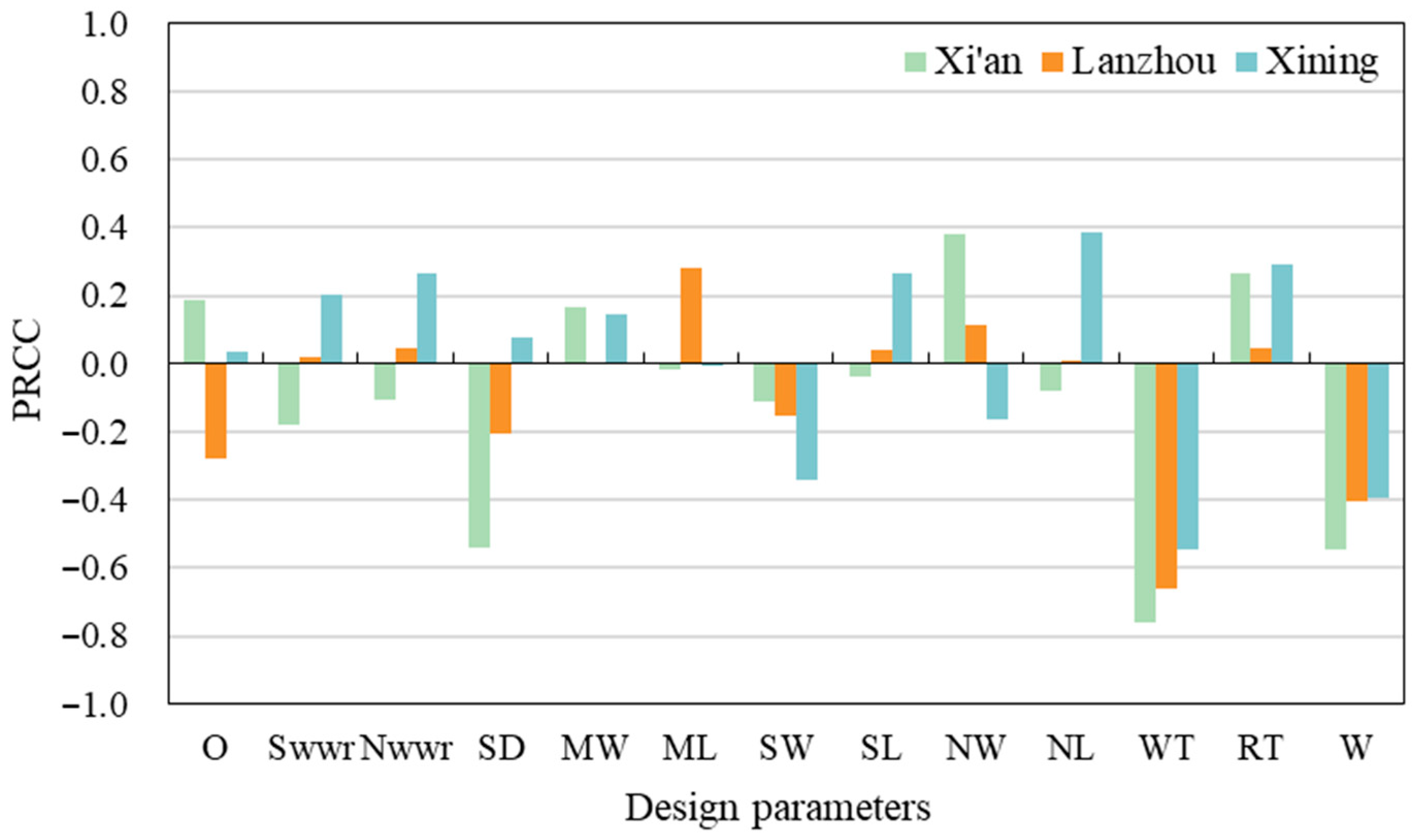
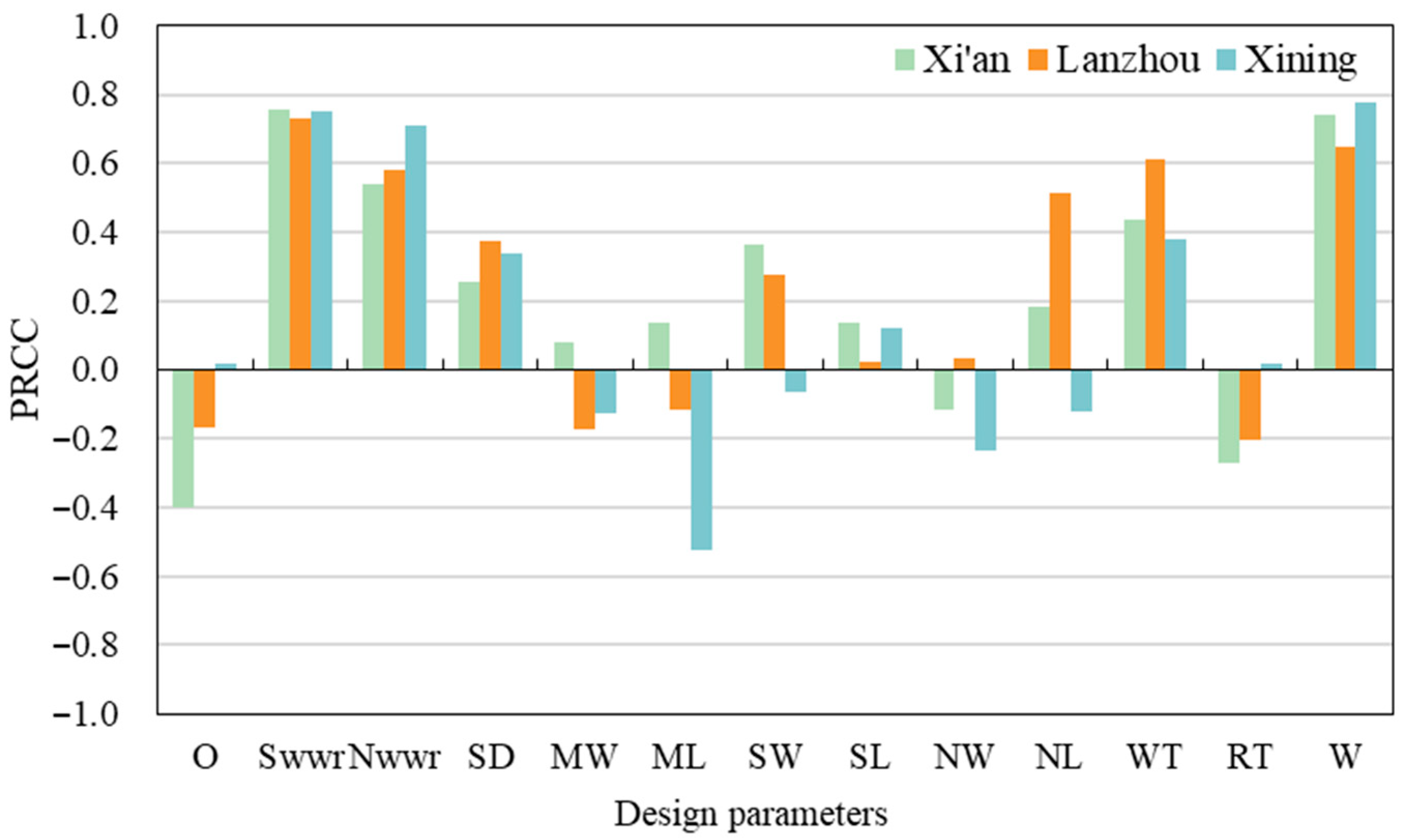
The rational selection of design variables directly impacts the achievement of the final objectives. In the schematic design stage, the design parameters controllable by architects are first screened out, then categorized into spatial form parameters and building envelope parameters, and the value ranges of the design variables are determined based on the survey results of high-rise residences. This paper selects thirteen design parameters as optimization variables, including ten spatial form parameters (e.g., building orientation, sunshade design, window−wall ratio, and main room dimensions) and three building envelope parameters (e.g., insulation layer thickness and window type).
Building orientation refers to the angle between the normal of a building’s main facade and the south direction. It exerts a notable influence on solar radiation reception and serves as a key factor during the building scheme design stage. In cold and severe cold regions, the orientation of high-rise residences directly affects heating, cooling, and lighting performance, thereby determining energy consumption efficiency, indoor light environment quality, and carbon emission levels. The window−wall ratio is one of the core parameters for controlling windows size, defined as the ratio of the total exterior window area to the total wall area of a specific orientation. As a key factor affecting building energy consumption, it is closely associated with environmental requirements such as indoor lighting. In high-rise residences, east- and west-facing windows are relatively small or even absent. Therefore, the window−wall ratios of the south and north facades are key aspects to be optimized. High-rise residences usually adopt horizontal overhang sun visors, which are installed at the upper edge of exterior windows and can not only enhance the layering effect of facade design but also ensure pleasant visual comfort within the residential building. Since the south facade receives the most solar radiation and typically has the largest window area, sun visors are installed on the south facade, with the overhang length selected as the design variable for optimization.
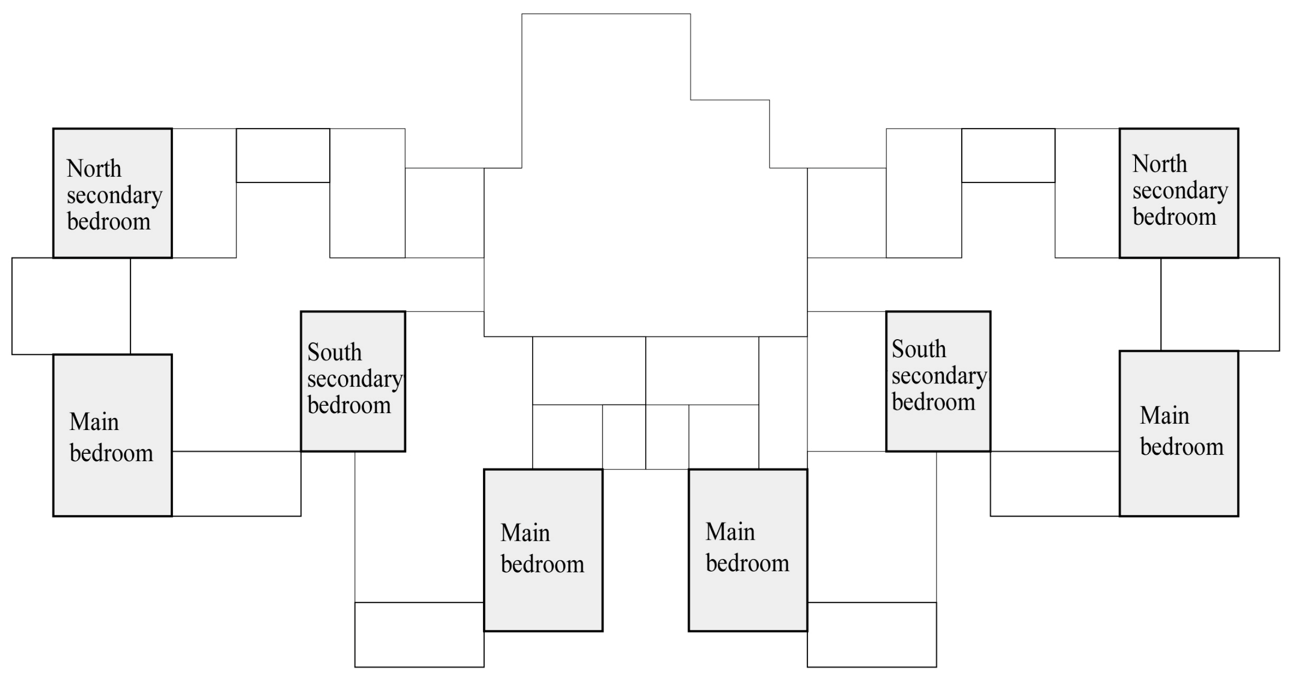
The bedroom, as a fundamental functional space in a residence, is also the room type accounting for the largest area proportion. Its size directly affects living comfort. Currently, the bedroom space in high-rise residence is gradually expanding, with each unit type equipped with at least two bedrooms, as shown in
Figure 8. Based on the room location and orientation, bedrooms are divided into the main bedroom, south-facing secondary bedroom, and north-facing secondary bedroom. Six design parameters are established, including the main bedroom width, main bedroom depth, south-facing secondary bedroom width, south-facing secondary bedroom depth, north-facing secondary bedroom width, and north-facing secondary bedroom depth. To meet actual usage requirements and avoid affecting the normal spatial scale of other rooms, extreme design scenarios (e.g., overly long or narrow rooms) are excluded. During the adjustment of design parameters, the following rule was maintained: the main bedroom area > south-facing secondary bedroom area > north-facing secondary bedroom area.
The thermal insulation performance of exterior walls and roofs, as the primary components of non-transparent envelopes, is determined by the heat transfer coefficient. At present, the predominant approach to improve this indicator in engineering practice is to incorporate an insulation layer. Since the load-bearing structure remains unchanged during the optimization process, the thickness of the exterior wall and roof insulation layers are selected as optimization variables, with extruded polystyrene board (XPS) adopted as the insulation material. Based on the limit values of heat transfer coefficients for exterior walls and roofs [
4], the range of the insulation layer thickness is determined. The exterior windows consist of window frames and glass, which are composed of glass plates, gas fillers, and spacers, and the thermal performance of exterior windows is jointly determined by these materials. Combining relevant standards with survey results, five types of exterior windows are selected as optimal design variables. The specific types and parameters are illustrated in
Table 5. Room dimensions, shading size, and other relevant parameters are determined based on surveys and building design datasets [
67].
In summary,
Table 6 summarizes the optimization variables and parameters for high-rise residences. The cost information and carbon emission factors of related materials and energy are displayed in
Table 7 and
Table 8.
2.2.5. Establishment of Prediction Model
By integrating the parameterized model, objective functions, and design variables, the Grasshopper plugin DSE was employed to couple with the performance model of high-rise residences for LHS of the design variables, and to complete the calculation of four objective functions. Using the generated “design variables–objective function” sample dataset, a multi-objective prediction model was established on the MATLAB R2021b platform. The sample data were split into a training set and a test set at a ratio of 8:2 [
57]. That is, 800 groups were used as the training set to develop the SVM prediction model, while 200 groups served as the test set to verify the model’s accuracy. The cross-validation method was applied to find the optimal parameters of the kernel function RBF:
c (the penalty factor) and
g (the variance of kernel function) Subsequently, the model was trained using the optimal parameters.
Two error evaluation indicators, R
2 and MSE, are employed to assess the predictive performance of the model. R
2 (coefficient of determination) serves as an indicator for measuring the overall fitting error. The calculation method is presented in Equation (22). Generally, a model with R
2 > 0.9 is considered reasonable, one with R
2 > 0.95 is regarded as precise, and with R
2 > 0.99 can be deemed nearly perfect [
34].
Therein, n is the sample count of test set, is the true value, is the predicted value, and is the average of true values.
The mean squared error (MSE) is a metric used to quantify the discrepancy between predicted values and actual values, and its calculation is expressed in Equation (23). This metric evaluates a model’s predictive performance by computing the average of the squared difference between the predicted values and true values. MSE is particularly sensitive to larger errors; if a model yields prediction with significant deviations, the MSE will rise substantially, thereby indicating the model requires further refinement.
In this paper, SVM prediction models were established for typical high-rise residences in Xi’an, Lanzhou, and Xining, respectively. The input parameters of the models include thirteen optimization design variables, while the output parameters consist of four objective functions. Through validation tests, the optimal parameters for RBF were determined as
c = 4.0 and
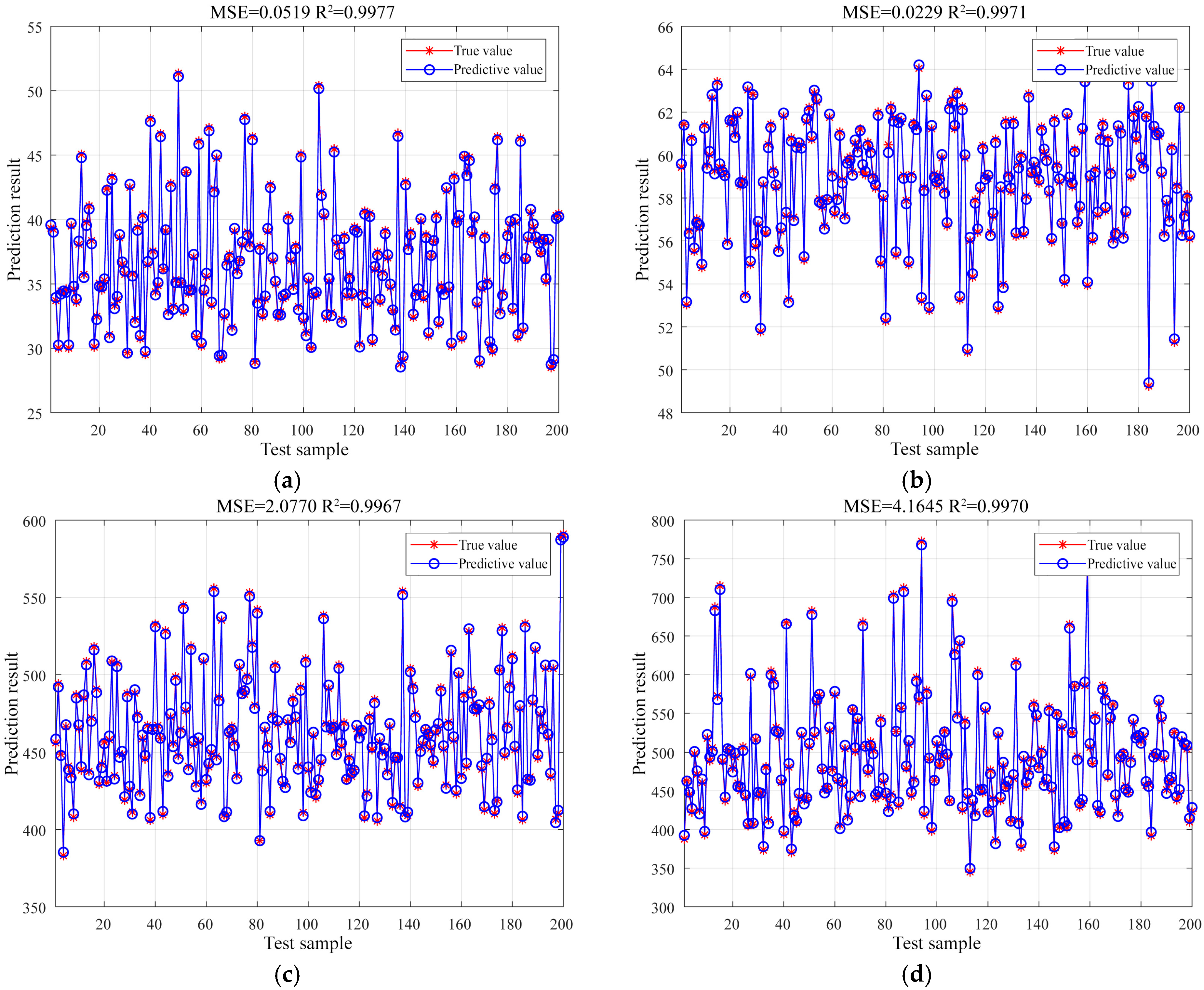
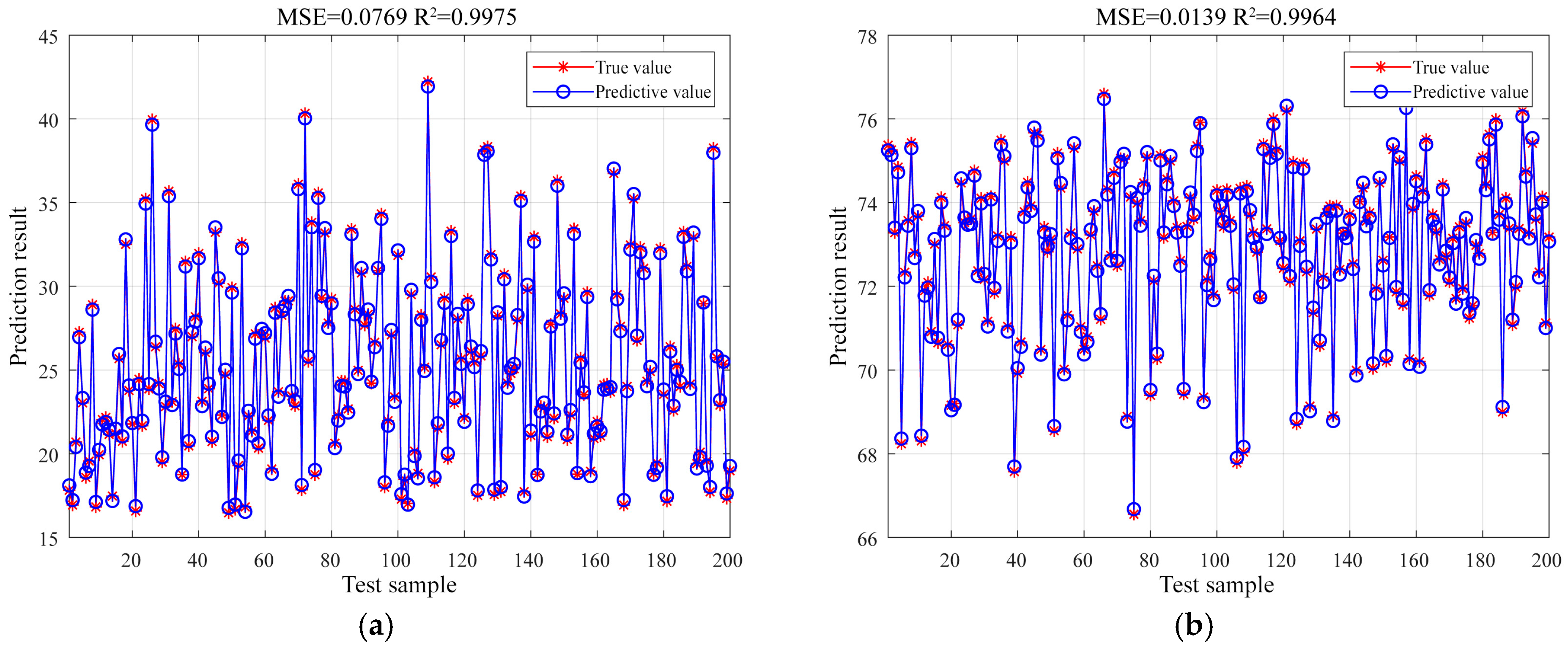
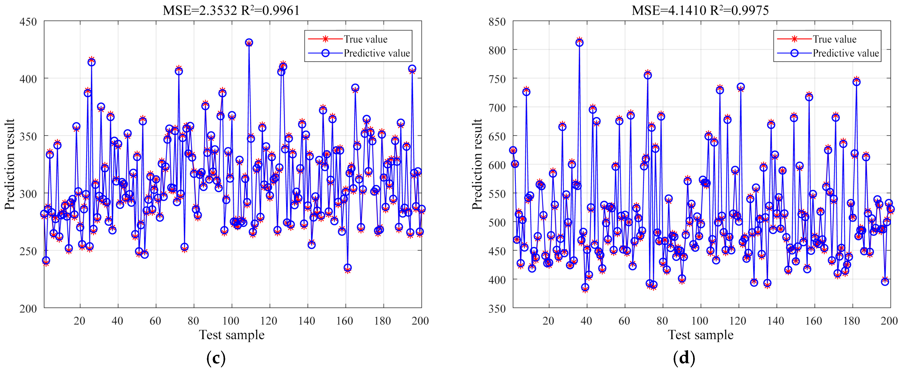
g = 0.8. Using these parameters, 800 sets of data were trained to develop SVM prediction models for each objective with respect to the design variables. Then, 200 sets of data from the test set were used for verification. Taking Xi’an City as an example, the test results are shown in
Figure 9. Specifically, for BEI, MSE = 0.0519, R
2 = 0.9977; for UDI, MSE = 0.0229, R
2 = 0.9971; for LCCO
2, MSE = 2.077, R
2 = 0.9967; and for LCC, MSE = 4.1645, R
2 = 0.9970. It indicates that the discrepancy between the simulated values and predicted values is extremely small, and the predicted results are reliable. Notably, the R
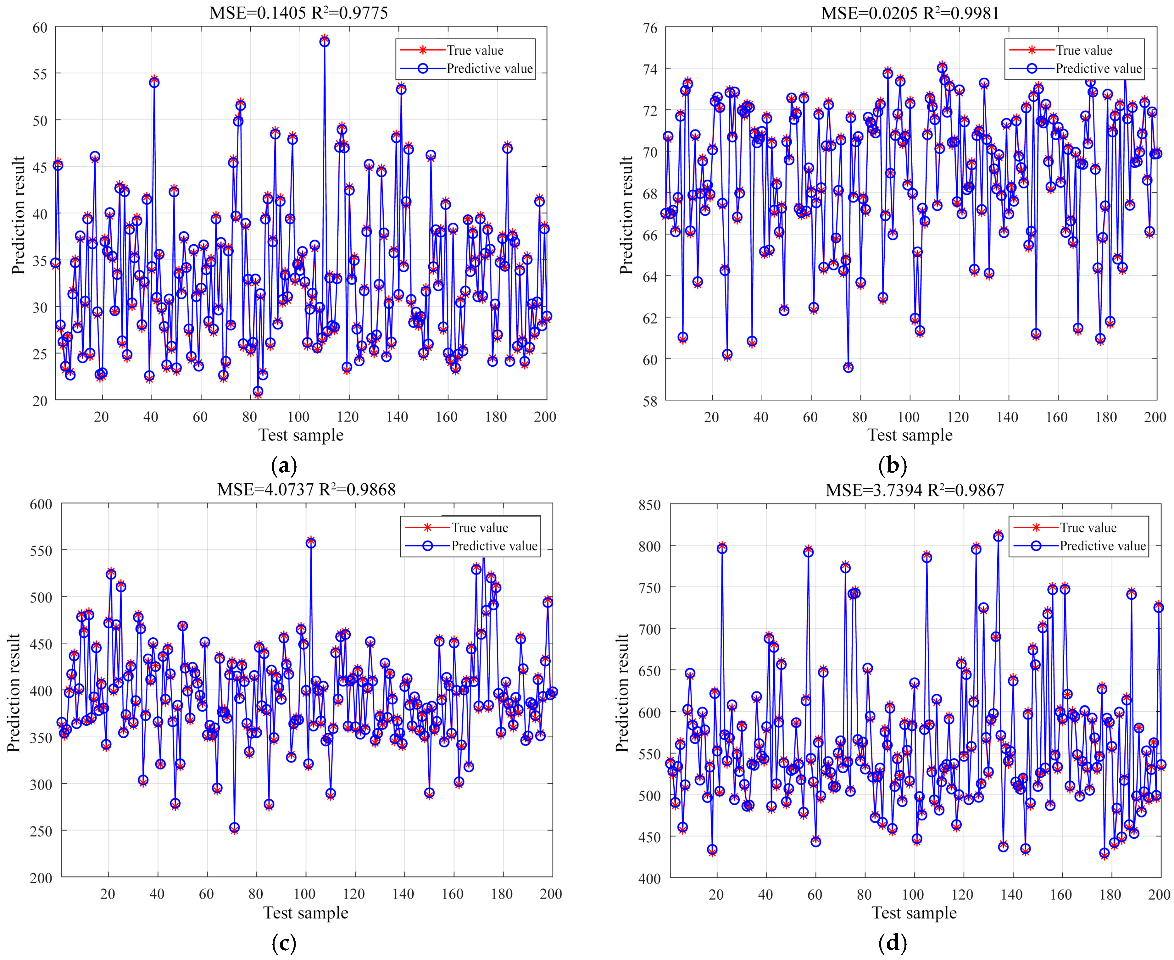
2 of all prediction models exceed 0.95. Similarly, the performance of the prediction models for the other two cities also meets the required standards and detailed results are provided in
Appendix A.