Article

Improving Acoustic Performance While Preserving Visual Connectivity in Small-Scale Industrial Buildings: An Integrated Acoustic Design Methodology

by
Mustafa İnce
and
Gülşen Akın Güler
*
Department of Architecture, Eskisehir Technical University, 26140 Eskisehir, Türkiye
*
Author to whom correspondence should be addressed.
Buildings 2026, 16(18), 3746; https://doi.org/10.3390/buildings16183746 (registering DOI)
Submission received: 9 August 2026 / Revised: 15 September 2026 / Accepted: 18 September 2026 / Published: 20 September 2026
(This article belongs to the Section Architectural Design, Urban Science, and Real Estate)

Abstract

Small-scale industrial buildings commonly accommodate production areas and office units within the same building, where visual connectivity between these spaces is required to facilitate the monitoring and supervision of production processes. However, this functional requirement may increase airborne noise transmission from production areas to adjacent office spaces, thereby adversely affecting acoustic comfort. This study proposes an integrated acoustic design approach to improve the acoustic performance of small-scale industrial buildings while preserving the required visual connectivity. A woodworking workshop and its adjacent office unit in the Design and Application Laboratory Building at Eskişehir Technical University were selected as a case study. Existing acoustic conditions were determined through in-situ noise measurements. The airborne sound insulation performance of individual building elements was evaluated using Prediction Sound Insulation (INSUL 6.2), while room-scale acoustic performance, including flanking sound transmission, was assessed using Kalksandstein (KS 8.03). The results identified the aluminum-framed glazed partition system as the dominant airborne sound transmission path between the workshop and the office. Following the numerical evaluation of the proposed design modifications, the DnT,A values were predicted to increase from approximately 33 dB to 57 dB, thereby exceeding the Class D acoustic performance criterion specified in the Turkish Regulation on the Protection of Buildings Against Noise (BGKKHY) for existing buildings. The results demonstrate that effective acoustic retrofit cannot be achieved by considering individual building elements alone, but requires the integrated evaluation of spatial organization, critical transmission paths, and receiver conditions. The proposed approach provides a practical framework for the acoustic design and retrofit of small-scale industrial buildings where visual supervision must be maintained.

1. Introduction

Noise is one of the most prevalent physical hazards in industrial environments and may adversely affect employee health, safety, comfort, and work performance. Prolonged exposure to elevated sound levels is associated not only with noise-induced hearing loss but also with annoyance, fatigue, sleep disturbance, cardiovascular responses, reduced concentration, and increased occupational accident risk [1,2,3,4,5]. These effects demonstrate that industrial noise should be addressed as both an occupational health issue and an architectural design problem.
Industrial facilities commonly contain machinery and production processes that generate continuous, intermittent, impulsive, and frequency-dependent noise. Continuous noise is characterized by sound that persists throughout the operating period, whereas intermittent noise is present only during distinct operating intervals separated by periods without the specific noise. Impulsive noise is characterized by brief bursts of sound pressure, typically associated with sudden impact or rapidly occurring operations. Frequency-dependent noise refers here to sound whose acoustic energy is unevenly distributed across the frequency spectrum, with dominant components varying according to the operating characteristics of the source [6,7]. In woodworking environments, continuously operating machinery can generate predominantly continuous noise, whereas start–stop operations may produce intermittent noise and cutting or impact-related processes may introduce impulsive components. The frequency-dependent characteristics of woodworking machinery are reflected in their source-specific octave-band spectra [6]. The resulting acoustic environment is influenced by the sound power and directivity of the sources, source–receiver distance, room geometry, surface absorption, machinery layout, and the acoustic characteristics of separating building elements [8,9,10,11,12]. In large workshops, sound emitted by machinery reaches receivers through both direct and reflected propagation paths. When wall, floor, and ceiling surfaces have low sound absorption, a substantial proportion of the incident acoustic energy is reflected back into the space rather than being absorbed. Repeated reflections increase the reverberant sound field, allowing acoustic energy to persist and propagate throughout the room and thereby contributing to elevated sound pressure levels away from the immediate vicinity of the source [13]. Consequently, effective noise control requires a systematic assessment of both individual sources and the spatial characteristics of the building.
Woodworking and furniture-production facilities are particularly relevant in this context because sawing, cutting, drilling, sanding, and extraction systems can produce high and fluctuating sound levels [8,14]. The directivity of woodworking machinery may also cause significant variations in sound exposure depending on the position and orientation of the source [8]. Noise mapping and source-characterization studies therefore provide valuable information for identifying dominant noise-generating equipment, evaluating worker exposure, and developing source-oriented control measures [9,10,11,12,15].
Administrative offices located within or adjacent to industrial production areas present an additional acoustic design challenge. Although employees in these offices are not always directly involved in production activities, they may be exposed to noise transmitted from neighboring workshops through walls, doors, glazing systems, ventilation openings, junctions, and other flanking paths. In office environments, irrelevant speech and equipment noise can impair concentration, increase perceived disturbance, reduce task performance, and negatively affect workplace satisfaction [16,17,18,19,20]. Adequate acoustic comfort in such spaces therefore depends on both the internal acoustic conditions of the office and the airborne sound insulation provided by the separating construction.
The acoustic performance of a partition is generally governed by its weakest component. Even when opaque wall sections provide relatively high sound insulation, glazed panels, doors, frames, seals, and wall–floor or wall–ceiling junctions may substantially reduce the overall field performance [21,22,23,24]. Laboratory sound reduction indices alone may therefore be insufficient for evaluating the real acoustic separation between adjacent rooms. Building-scale performance must also account for room geometry, reverberation conditions, workmanship, junction characteristics, and flanking transmission.
Glazed partition systems are frequently used to provide daylight, supervision, communication, and visual connectivity between production and administrative spaces. However, the acoustic performance of glazing depends on several variables, including pane thickness, cavity depth, glass asymmetry, lamination, frame construction, sealing quality, and installation conditions [21,22,23]. Increasing the number or thickness of glass layers does not automatically ensure satisfactory field sound insulation unless the framing, door assemblies, perimeter seals, and adjoining building elements are designed as an integrated system. Accordingly, the acoustic performance of a glazed partition should be considered at both the element and room scales. At the element scale, parameters such as pane thickness, cavity depth, glazing configuration, frame construction, and sealing primarily determine the sound insulation performance of the partition itself. At the room scale, the resulting acoustic separation between adjacent spaces is additionally influenced by partition area, room geometry, reverberation conditions, junction characteristics, and flanking transmission. Therefore, the building-scale performance of a glazed partition depends not only on its material and construction properties but also on the acoustic characteristics of the spaces in which it is installed [25].
Noise control strategies are commonly classified according to the source–transmission path–receiver approach. Source control includes selecting quieter equipment, applying maintenance procedures, reducing vibration, enclosing machinery, and modifying operational conditions. Transmission-path control involves increasing the sound insulation of walls, doors, glazing systems, and junctions, as well as introducing absorptive finishes to reduce reverberant sound propagation. Receiver control may include workplace relocation, spatial zoning, acoustic screens, sound-absorptive finishes, and the reorganization of noise-sensitive activities [10,12,26,27,28]. The effectiveness of these strategies is generally greater when they are considered together rather than as isolated measures.
Numerical prediction tools can support this integrated design process by enabling alternative constructions to be evaluated before implementation. Element-based calculation tools can estimate the laboratory sound reduction index of multilayer wall and glazing systems, while building-acoustic models can incorporate room dimensions, junctions, façade and partition elements, and flanking transmission to predict apparent sound insulation and standardized level differences. The combined use of laboratory-scale and building-scale prediction methods therefore provides a more reliable basis for comparing design alternatives and identifying the most influential transmission paths [22,23,24].
Despite extensive research on occupational noise exposure, industrial noise mapping, open-plan office acoustics, and the sound insulation performance of individual building elements, relatively few studies have addressed the acoustic design of office spaces that must maintain direct visual connectivity with adjacent noisy production areas. This gap is particularly relevant in small-scale industrial buildings, where spatial separation or the introduction of buffer zones may not be feasible because of operational requirements. In such cases, improving acoustic performance requires not only higher-performing construction elements but also the coordinated consideration of spatial organization, dominant transmission paths, visual connectivity, implementation feasibility, and retrofit constraints. Accordingly, there is a need for building-scale design approaches that integrate these parameters within a practical acoustic retrofit framework.
Accordingly, this study investigates the acoustic performance of a woodworking workshop and an adjacent office located in an industrial educational building. Existing acoustic conditions were evaluated through field measurements and numerical analyses, and the dominant airborne sound transmission paths were identified. Alternative design solutions were then developed within an integrated source–transmission path–receiver framework and comparatively assessed in terms of predicted acoustic performance, regulatory compliance, visual connectivity, and practical applicability. The contribution of this study does not lie in the development of new acoustic measurement or prediction methods, but in the integrated application of established acoustic assessment and noise-control approaches to a specific architectural retrofit problem in which acoustic improvement must be achieved without compromising the operational requirement for visual supervision. The study therefore presents a case-based building-scale design framework that links element-level sound insulation performance with spatial organization, flanking transmission, functional requirements, and the preservation of visual connectivity. Rather than proposing a universally applicable methodology, the framework is intended to provide a structured basis for acoustic retrofit decision-making in industrial buildings with similar functional constraints.
More specifically, the proposed framework differs from the conventional source–transmission path–receiver approach by using this established classification as the starting point of a constraint-based retrofit decision process rather than as the final structure of the acoustic assessment. Likewise, the framework does not modify or replace the calculation principles of EN 12354; instead, EN 12354-based building-scale predictions are incorporated as one component of a broader design process. The distinctive contribution is the explicit linkage of (i) field-based source characterization, (ii) element-level sound insulation prediction, (iii) building-scale assessment of direct and flanking transmission, (iv) identification and targeted redesign of the acoustically weakest partition components, and (v) evaluation of the resulting alternatives against acoustic performance, regulatory compliance, visual-supervision requirements, and practical retrofit constraints. Thus, the contribution lies in the structured integration of established acoustic methods with architectural and operational constraints that are not, by themselves, addressed by the source–path–receiver classification or EN 12354 calculation procedures.

2. Materials and Methods

2.1. Research Framework

This study was conducted using a four-stage research framework to develop acoustic design strategies for office spaces requiring visual connectivity with production areas in small-scale industrial buildings. In the first stage, national and international literature on industrial noise control, building acoustics, acoustic design principles, and relevant regulations was comprehensively reviewed.
In the second stage, the Design and Application Laboratory Building at Eskişehir Technical University was selected as the case study. The architectural, functional, and acoustic characteristics of the woodworking workshop and the adjacent office unit were systematically evaluated. Within this stage, the primary noise sources were identified, the spatial relationship between the production area and the office was analyzed, and the building elements influencing the acoustic performance were determined.
In the third stage, the building was assessed based on the principles of source control, transmission path control, and receiver control, and alternative design solutions were developed where necessary. The existing acoustic conditions were determined through in-situ noise measurements, while the airborne sound insulation performance of the partition systems was numerically evaluated using the INSUL (Auckland, New Zealand) and Kalksandstein (KS) (Hannover, Germany) software. The obtained results were compared with the acoustic performance criteria specified in the Turkish Regulation on the Protection of Buildings Against Noise (BGKKHY) [28]. In addition to the sound insulation performance of individual building elements, the site layout, spatial organization, visual connectivity, and office interior layout were evaluated as integrated components of the acoustic design process.
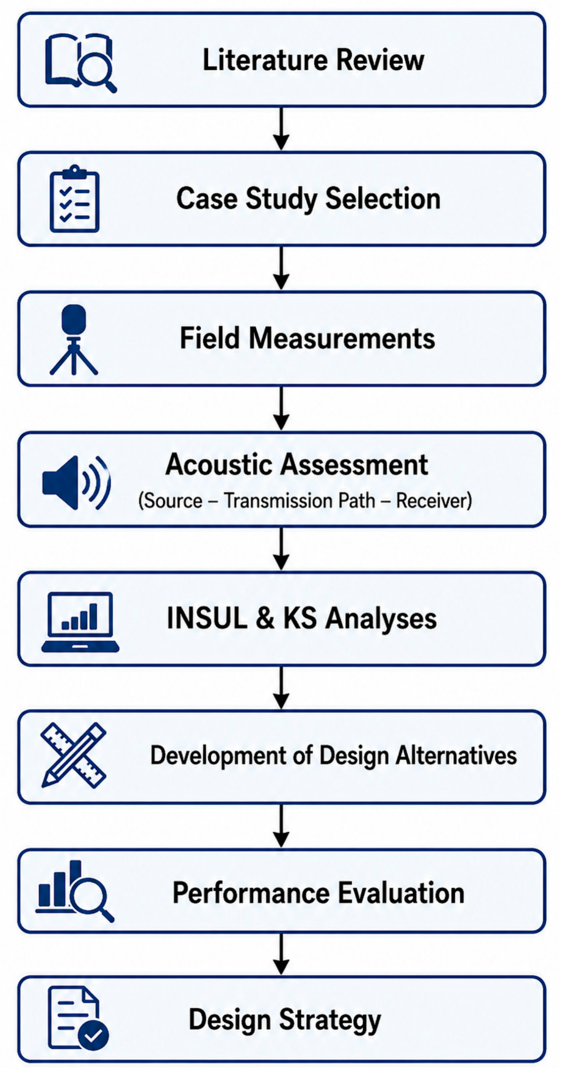
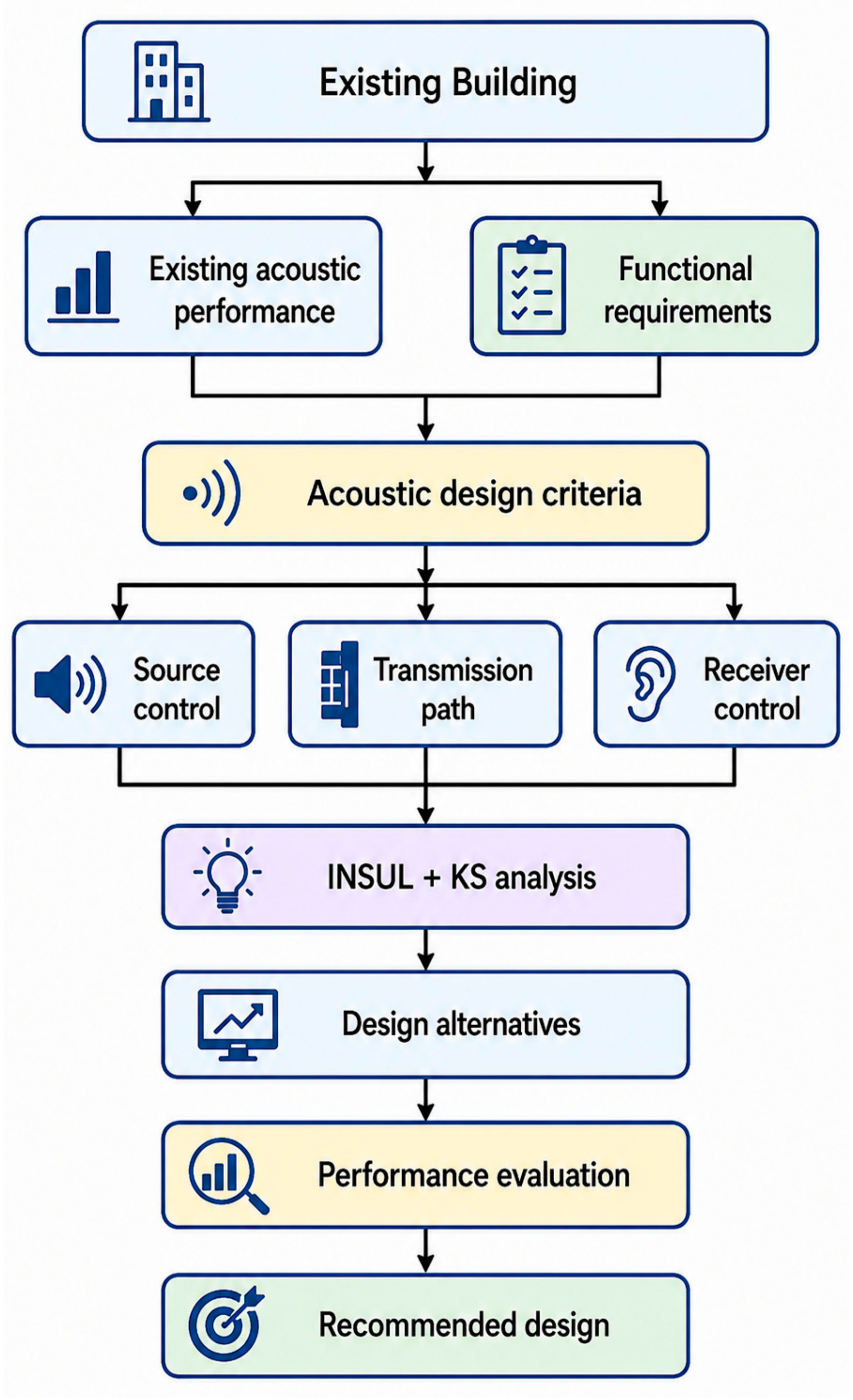
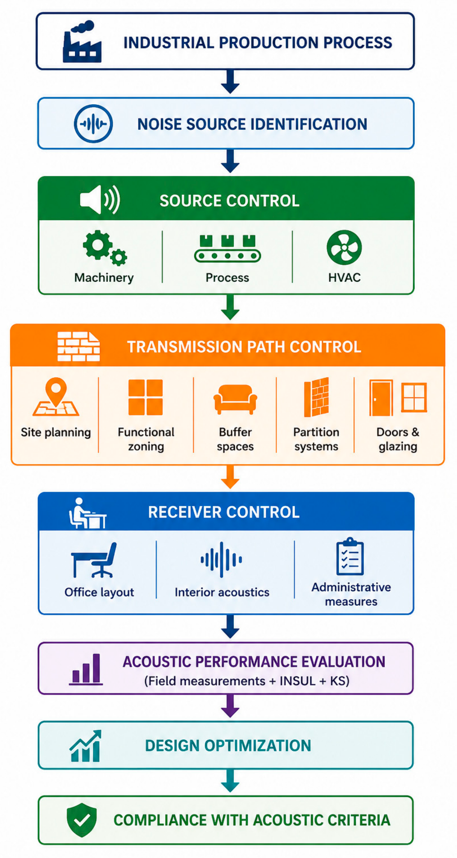
In the final stage, the acoustic performance of the proposed design alternatives was compared with the existing conditions, and practical acoustic design principles for small-scale industrial buildings integrating production areas and office spaces were established. The overall methodological framework of the study is presented in Figure 1.

2.2. Case Study Building

The Design and Application Laboratory Building, located on the İki Eylül Campus of Eskişehir Technical University, was selected as the case study for this research (Figure 2). The building represents a typical spatial configuration commonly found in small-scale industrial facilities, where production and administrative functions are accommodated within the same structure [29,30,31]. The coexistence of a woodworking workshop and an adjacent office unit provides an appropriate environment for investigating spaces with substantially different acoustic requirements. Therefore, the building was considered a representative case for evaluating the acoustic relationship between noisy production areas and noise-sensitive working spaces in industrial environments.
The selection of this case study was based not only on its accessibility but also on its representativeness. The building reflects a common operational scenario in small-scale industrial facilities, where production areas and office spaces are located within the same building and direct visual connectivity between them is required for process supervision and management. Accordingly, the objective of this study is not statistical generalization but the development of acoustic design strategies through an in-depth analysis of a representative case exhibiting an acoustic–visual design conflict.
The woodworking workshop was selected because it contains multiple high-noise woodworking machines with different acoustic characteristics, resulting in a complex airborne noise environment representative of many educational workshops and small-scale manufacturing facilities [6,14,32]. Nevertheless, the proposed design strategies are not limited to woodworking workshops and may also be applied to other industrial buildings in which visual supervision between production areas and acoustically sensitive spaces is required.
Figure 2. Location of the Design and Application Laboratory Building within Eskişehir Technical University Campus [33].
Buildings 16 03746 g002
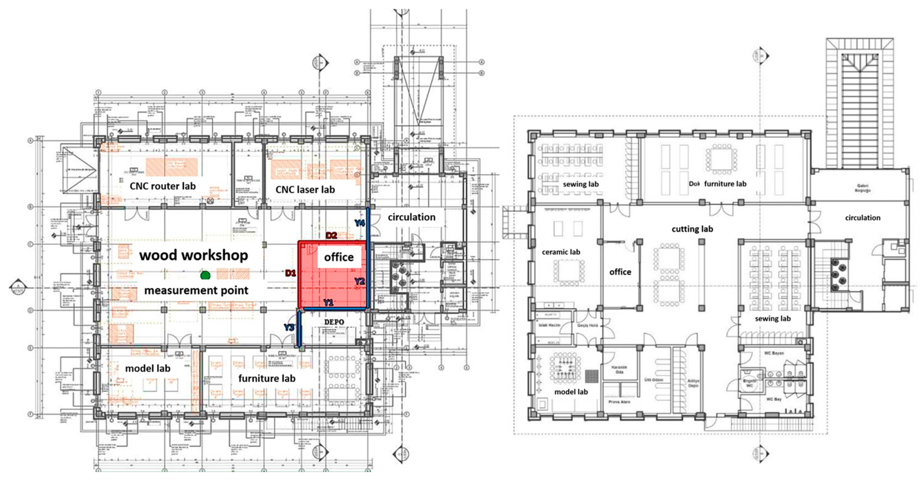
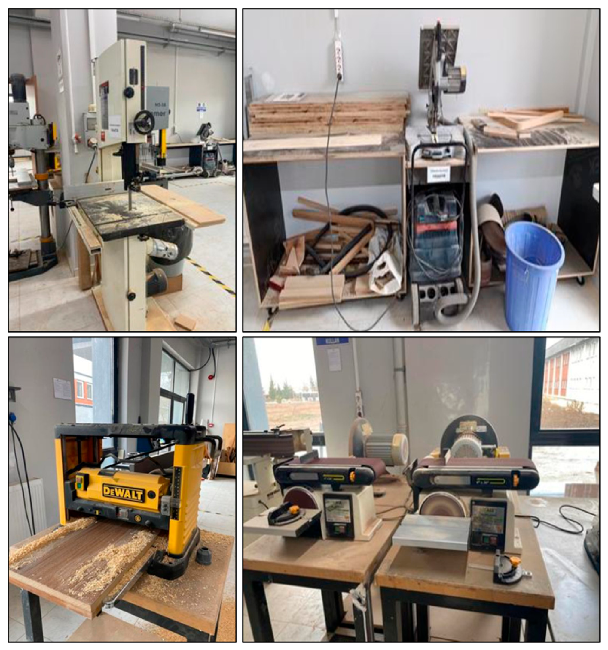
The ground floor of the case study building consists of a woodworking workshop and an adjacent office unit directly connected to the production area (Figure 3). The workshop is equipped with various woodworking machines, including a circular saw, band saw, surface planer, thickness planer, spindle moulder, drill press, and sanding equipment. During cutting, shaping, drilling, planing, and surface-finishing operations, these machines generate both continuous and impulsive airborne noise due to the interaction between high-speed motors, cutting tools, and wooden materials. In addition to the production machinery, the dust extraction system and other auxiliary mechanical equipment also contribute to the overall noise level within the workshop.
The office unit adjacent to the woodworking workshop is used for academic and administrative activities. Typical activities performed within the office include communication, meetings, computer-based tasks, and individual work, all of which require a high level of concentration and speech intelligibility [16,17,34]. Consequently, the office has substantially stricter acoustic requirements and requires significantly lower background noise levels than the adjacent production area.
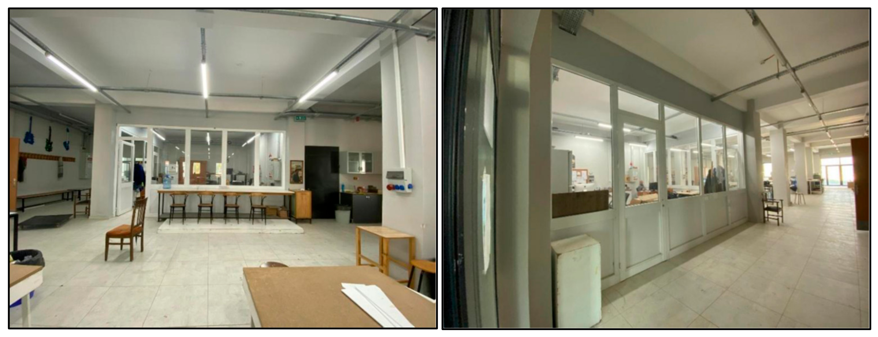
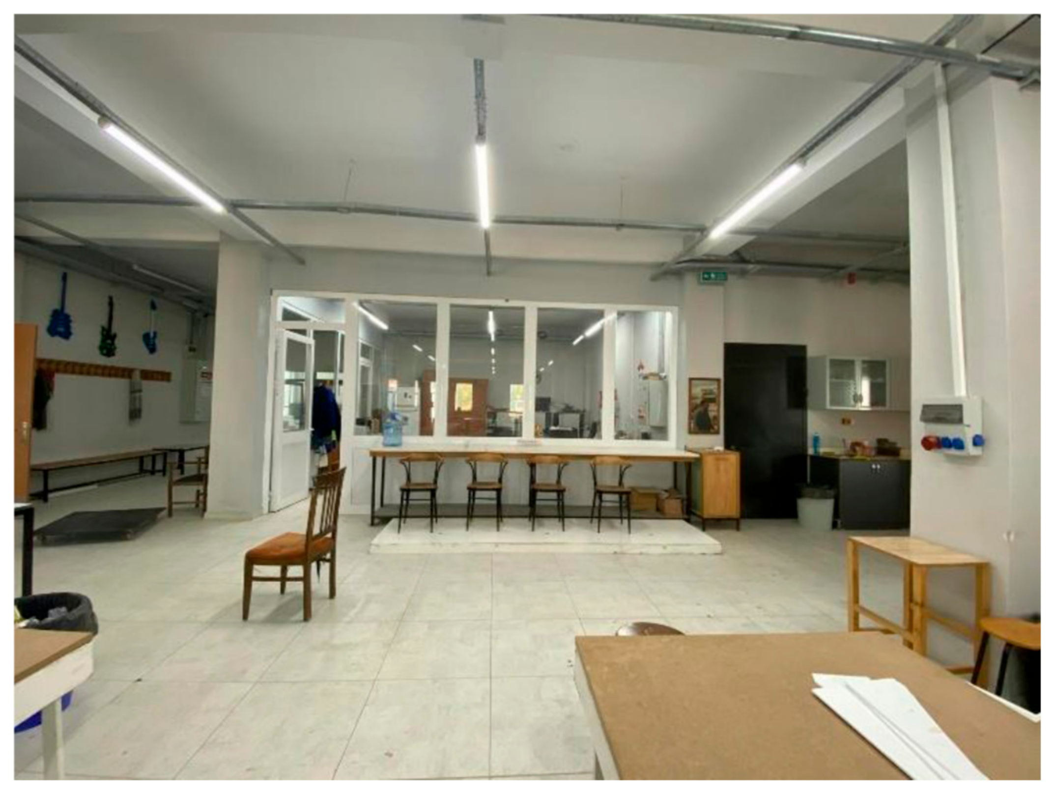
The most distinctive feature of the case study building is the direct visual connectivity established between the office and the production area for operational purposes (Figure 4). To facilitate process supervision, ensure occupational safety, and enable continuous monitoring of production activities, the two spaces are separated by partition systems incorporating large glazed surfaces. While this spatial configuration effectively preserves visual continuity, it also facilitates the transmission of airborne noise from the woodworking workshop to the office, creating a significant acoustic design challenge [21,22,25,35]. Achieving an appropriate balance between visual accessibility and acoustic comfort therefore constitutes the primary focus of this study.
During this stage, the production machinery, auxiliary equipment, and supporting mechanical systems in the woodworking workshop were systematically evaluated to identify the principal airborne noise sources within the production area.

2.3. Acoustic Assessment

2.3.1. Source Control Assessment

In the first stage, the building layout and external environmental noise sources were evaluated. The principal external noise sources potentially affecting the Design and Application Laboratory Building were identified as road traffic and aircraft operations, which are generally recognized as the dominant environmental noise sources affecting buildings and occupants [7,36,37]. However, the surrounding educational buildings, administrative facilities, and social areas do not constitute significant environmental noise sources. According to the strategic noise maps prepared by the Eskişehir Metropolitan Municipality, the building is located within a noise zone of 55 dB(A) or below. Therefore, road traffic noise was not considered a dominant factor affecting the indoor acoustic environment within the scope of this study.
Similarly, aircraft noise was found to have a negligible influence on the building under current operating conditions. Flight statistics for Hasan Polatkan Airport at Eskişehir Technical University indicate a total of 888 aircraft movements in 2023, corresponding to approximately two to three flights per day. Considering the relatively low flight frequency and the short duration of aircraft pass-by events, aircraft noise was not considered to significantly influence the continuous acoustic conditions within the office space [38,39].
Following the assessment of external noise sources, the production machinery, auxiliary equipment, and supporting mechanical systems operating in the woodworking workshop were systematically evaluated to identify the principal airborne noise sources. The workshop contains a wide range of woodworking machinery, including circular saws, mitre saws, surface planers, thickness planers, horizontal panel saws, band saws, drill presses, wood lathes, oscillating sanders, vertical drum sanders, and other cutting and drilling equipment (Figure 5). During cutting, shaping, drilling, planning, and finishing operations, these machines generate both continuous and impulsive airborne noise due to the interaction between high-speed motors, cutting tools, and wooden materials [40,41,42,43].
In addition to the production machinery, auxiliary systems such as the dust extraction system, ventilation equipment, and portable power tools also contribute to the overall sound pressure levels within the workshop [41,43,44]. Among these sources, the woodworking machines used for cutting and shaping operations were identified as the dominant contributors to the acoustic environment because of their relatively high sound pressure levels and long operating durations. Consequently, the production machinery and associated auxiliary systems were considered the primary noise sources affecting the acoustic performance of the adjacent office, and subsequent noise-control evaluations were carried out based on these sources.

2.3.2. Transmission Path Assessment

The assessment of the transmission path began with the evaluation of the building layout in relation to external noise sources. The office unit is not directly exposed to the building façade and is separated from the outdoor environment by buffer spaces, including the woodworking workshop, storage rooms, and circulation areas. This spatial configuration provides an effective barrier against environmental noise [23,24,45]. Consequently, external noise sources were not considered the primary factor governing the acoustic performance of the office space.
Subsequently, the spatial organization of the building was evaluated in terms of the noise–sensitivity hierarchy. As shown in Figure 6, the woodworking workshop and the adjacent office were intentionally designed as directly connected spaces to facilitate production supervision, communication, and operational management. Although this layout offers significant functional advantages, it also creates a critical acoustic condition by placing the noisiest production space immediately adjacent to one of the most acoustically sensitive areas within the building [26,44,45].
The woodworking workshop represents the dominant noise-generating space, whereas the adjacent office is used for activities requiring concentration, communication, and individual work (Table 1). In addition, the office shares a wall with the vertical circulation area, introducing an additional transmission path that should be considered in the overall acoustic assessment. These findings indicate that the acoustic performance of the office is governed not only by the sound insulation performance of the partition systems but also by the spatial organization and functional relationships between adjacent spaces [45,46].
Finally, the spatial layout was evaluated with respect to internal noise transmission. The office unit was intentionally located adjacent to the woodworking workshop to facilitate continuous supervision, communication, and management of production activities. Consequently, maintaining direct visual connectivity between the two spaces represents an operational requirement. Under these conditions, conventional noise-control strategies such as introducing buffer spaces, increasing the separation distance between functions, or relocating the office were not considered practical. Therefore, improving the acoustic performance of the partition systems rather than modifying the spatial layout was identified as the most feasible noise-control strategy [26,45,46].
Accordingly, the building elements separating the workshop and the office were investigated in detail. The assessment included walls, glazed partitions, doors, floor slabs, and ceiling systems. The layer configurations of these elements were identified based on the architectural drawings, and their airborne sound insulation performance was subsequently evaluated [45,46].
The primary partition system between the woodworking workshop and the office consists of aluminum-framed glazed partitions incorporating glazed door systems. Owing to the extensive glazed surfaces and lightweight metal framing, this assembly was identified as the most critical element governing airborne sound transmission [21,23,45] between the two spaces. In contrast, the double-leaf aerated concrete wall separating the office from the vertical circulation area, incorporating a 50 mm air cavity, provides an estimated airborne sound insulation performance of approximately Rw = 70 dB [45,46].
This finding indicates that the principal acoustic deficiency of the office is associated with the glazed partition system adjacent to the production area rather than with the surrounding opaque building elements.
Based on these findings, the subsequent numerical analyses focused primarily on the glazed partition and door systems located between the workshop and the office. The airborne sound insulation performance of these partition systems was evaluated in accordance with the Turkish Regulation on the Protection of Buildings Against Noise (BGKKHY), and the Class D acoustic performance requirements for existing buildings were adopted as the reference performance criteria. Consequently, the glazed partition systems were identified as the critical transmission path and selected for detailed numerical analysis.

2.4. Field Measurements and Numerical Analysis

2.4.1. Noise Measurements

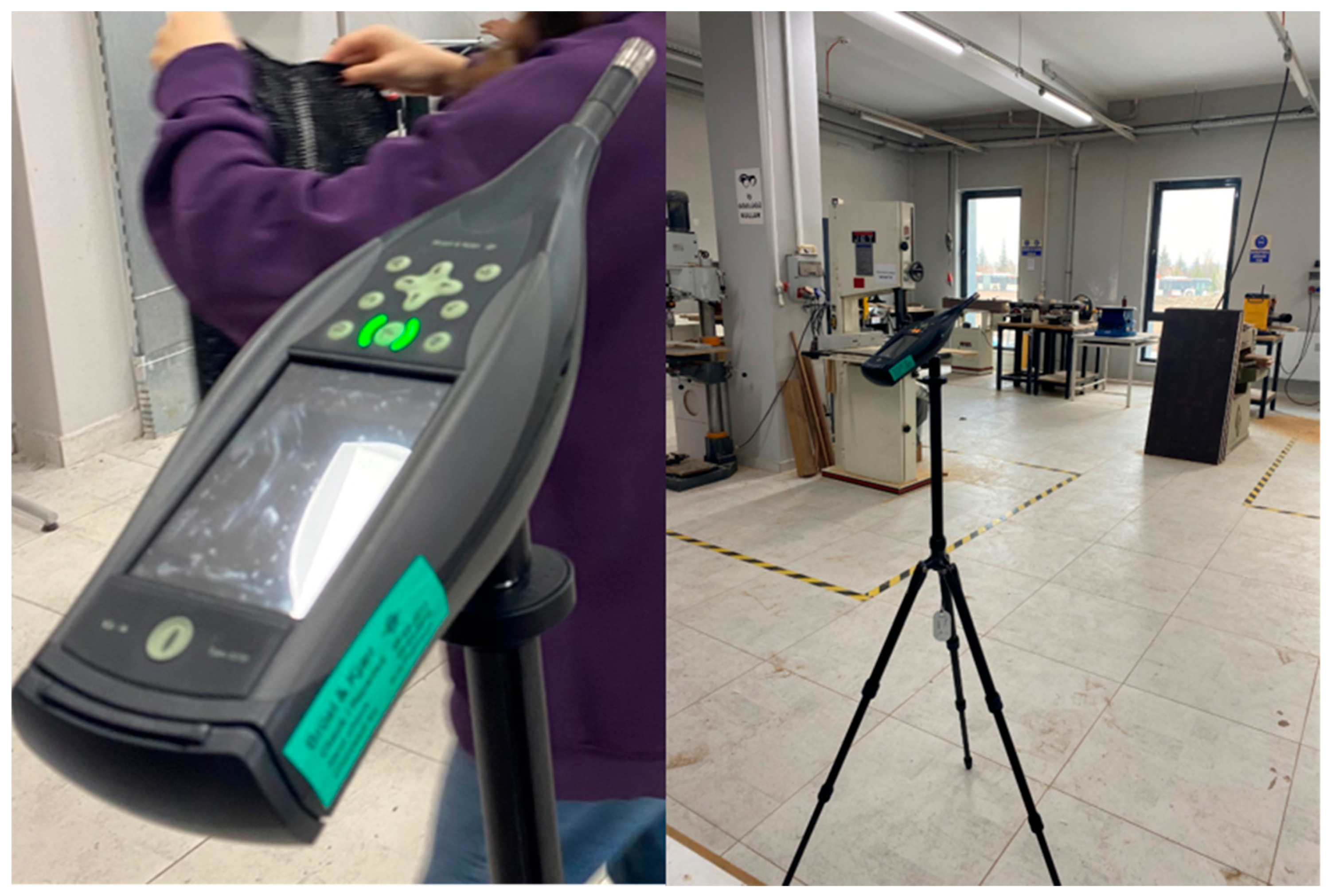
To determine the existing acoustic conditions, in-situ noise measurements were conducted in the woodworking workshop. The measurements were performed using a B&K Type 2270 (Nærum, Denmark) sound level analyzer (Figure 7) in accordance with TS EN ISO 9612 [47], which specifies procedures for assessing occupational noise exposure. A task-based measurement strategy was adopted, with all production machinery operating under normal working conditions to represent the typical acoustic environment of the workshop.
Measurements were carried out at the center of the workshop using a tripod-mounted sound level analyzer positioned 1.55 m above the floor. According to TS EN ISO 9612 [47], each measurement was repeated three times with a duration of 5 min per measurement. In accordance with the standard, additional measurements were performed whenever the difference between repeated measurements exceeded 3 dB. All measurements were conducted during normal working hours (08:00–17:00). The 5-min measurement interval was selected within the task-based measurement strategy to capture the acoustic conditions during representative periods of normal workshop operation, during which the principal production machinery was operating. Rather than relying on a single short-term measurement, three repeated 5-min measurements were conducted to account for short-term variability in the noise environment, with additional measurements performed when the difference between repeated measurements exceeded 3 dB. Accordingly, the measurements were intended to characterize the typical source-noise conditions prevailing during active workshop operation rather than to represent full-shift personal noise exposure. The sound level analyzer was calibrated before the measurements, and the calibration record was obtained. During the measurements, the ambient temperature and relative humidity were recorded as 21.7 °C and 37.6%, respectively, based on the digital measurement display available in the space.
The measurement campaign included the determination of the equivalent continuous sound pressure level (LAeq), maximum sound pressure level (LAmax), minimum sound pressure level (LAmin), peak sound pressure level (LCPeak), and maximum Z-weighted sound pressure level (LZFmax). In addition, one-octave band sound pressure levels within the frequency range of 31.5–8000 Hz were measured to establish the source noise spectrum used in the subsequent numerical analyses. It should be noted that the field measurements conducted in this study were used exclusively to characterize the existing noise environment within the woodworking workshop. The airborne sound insulation performance of the separating building elements was not measured in situ. Accordingly, the Rw values reported for individual building elements were obtained from INSUL predictions, whereas the R′w, DnT,w, and DnT,A values were obtained from KS calculations. Therefore, all sound-insulation performance values reported for the existing and proposed partition systems should be interpreted as model-derived values rather than field-measured quantities.

2.4.2. INSUL Analysis

The theoretical airborne sound insulation performance of the partition systems between the woodworking workshop and the office was evaluated using INSUL 6.2 [48]. The software was selected because it provides reliable predictions of the laboratory airborne sound insulation performance of multilayer building elements, employs internationally recognized calculation models [48,49], and enables rapid comparison of alternative building assemblies.
The geometrical dimensions and layer configurations of the existing building elements were obtained from the architectural drawings, whereas the material properties required for the acoustic calculations, including material densities, were assigned using the INSUL material database. These data were incorporated into the numerical model according to the corresponding material types and layer configurations. The assessment included all major building elements contributing to airborne sound transmission, including the ceiling, floor slab, aerated concrete wall systems, and the aluminum-framed double-glazed partition systems separating the workshop from the office.
INSUL predicts the airborne sound insulation performance of multilayer building elements by calculating frequency-dependent Transmission Loss (TL) curves based on the physical properties of the constituent layers [48,49]. The calculated sound insulation spectra were then rated in accordance with EN ISO 717-1 to obtain the weighted sound reduction index (Rw) [50].
The material properties and layer configurations used in the numerical analyses are summarized in Table 2. For each building element, frequency-dependent Transmission Loss (TL) curves and Rw values were calculated. The resulting Rw values were subsequently used as input parameters in the Kalksandstein (KS) analyses to determine the apparent airborne sound insulation performance at the building scale [45,51].
For the D1 and D2 systems, the glazing and door assemblies were represented in INSUL using the layer sequences, material properties, thicknesses, and cavity configurations specified in Table 2. Frame construction, perimeter seals, and workmanship were not introduced as independently parameterized acoustic elements in the INSUL model. Accordingly, the numerical predictions assume properly installed assemblies with continuous perimeter sealing and without significant unintended acoustic leakage at frames or junctions.

2.4.3. Kalksandstein (KS) Analysis

The Kalksandstein (KS 8.03) software was used to evaluate the apparent airborne sound insulation performance of the building at the room scale [45]. While INSUL predicts the laboratory airborne sound insulation performance of individual building elements, KS evaluates the apparent sound insulation performance under actual building conditions by considering junction details, room geometry, and flanking sound transmission [45,46,51]. Therefore, the two software packages were used in a complementary manner to assess both element-level and building-level acoustic performance.
The Rw values obtained from the INSUL analyses, together with the room dimensions, partition areas, and junction details extracted from the architectural drawings, were incorporated into the KS model. The analyses considered the geometry of the source and receiving rooms, the separating building elements, and the indirect sound transmission paths through adjacent structural components [22,45,46]. In the KS calculations, D1 and D2 were represented as composite separating systems using the INSUL-derived sound reduction indices and the corresponding surface areas of their constituent elements. Room geometry and junction configurations were defined from the architectural drawings, while flanking transmission through the floor, ceiling, and adjoining wall systems was included in the building-scale calculation. The model therefore accounts for the principal direct and flanking transmission paths but does not explicitly simulate local workmanship defects, discontinuous perimeter sealing, or unintended air gaps that may occur during construction.
The KS software predicts the apparent airborne sound insulation performance of buildings in accordance with the calculation procedures specified in EN 12354-1 [46]. The standardized level difference (DnT) between the source and receiving rooms is calculated as:
D nT = L 1 L 2 + 10 log 10 ( T To )
where
L1 is the average sound pressure level in the source room (dB);
L2 is the average sound pressure level in the receiving room (dB);
T is the reverberation time of the receiving room (s);
T0 is the reference reverberation time (0.5 s).
The calculated DnT values were subsequently evaluated according to TS EN ISO 717-1 to determine the weighted standardized level difference (DnT,w) and the A-weighted standardized level difference (DnT,A) [50]. Consequently, the analyses account not only for the laboratory sound insulation performance of individual building elements but also for the influence of room geometry, junction details, and flanking sound transmission under actual building conditions.
For each analysis model, the apparent sound reduction index (R′w), weighted standardized level difference (DnT,w), and A-weighted standardized level difference (DnT,A) were calculated. These indices describe different aspects of airborne sound insulation and should therefore not be interpreted as directly equivalent quantities. Rw represents the weighted sound reduction index of an individual building element under reference conditions and, in this study, was obtained from the INSUL predictions. In contrast, DnT,w represents the weighted standardized level difference between the source and receiving rooms and therefore reflects the overall building-scale acoustic separation, including the effects of the separating construction, room geometry, receiving-room reverberation time, junction conditions, and flanking transmission. DnT,A is derived from the frequency-dependent standardized level difference using the spectrum adaptation procedure and expresses the resulting airborne sound insulation as an A-weighted performance quantity. Consequently, differences between Rw, DnT,w, and DnT,A arise because they represent different assessment scales and weighting procedures: Rw characterizes element-level sound insulation, DnT,w characterizes standardized room-to-room sound insulation, and DnT,A provides the corresponding A-weighted performance value used for comparison with the BGKKHY criterion in this study. The resulting performance values were compared with the Class D acoustic performance requirements for existing buildings specified in the Turkish Regulation on the Protection of Buildings Against Noise (BGKKHY). The geometric parameters used in the KS analyses are summarized in Table 3.

2.5. Development of Design Strategies

Based on the findings of the acoustic assessment, design strategies were systematically developed to improve the acoustic performance of the office while maintaining the required visual connectivity with the woodworking workshop. The proposed strategies were not only intended to eliminate the acoustic deficiencies identified in the existing building but also to preserve the operational and functional relationship between the production and office spaces. Accordingly, acoustic performance, functional requirements, and practical applicability were considered simultaneously throughout the design process. In this study, visual connectivity was assessed primarily as a functional architectural requirement, while the positioning of the glazed area also considered the visual field of seated and standing users. The assessment was based on three criteria: (i) retention of a transparent glazed separation between the office and the woodworking workshop, (ii) positioning of the glazed area to provide a direct and unobstructed view of the workshop area for both seated and standing users in the office, and (iii) preservation of the ability to visually supervise the main workshop activities. Visual connectivity was considered to be preserved when these functional and visual criteria were maintained in the proposed retrofit configuration.
The development of the design strategies followed a three-step approach. First, the critical acoustic deficiencies of the existing building were identified through the evaluation of the noise source, transmission path, and receiver. Particular attention was given to the glazed partition systems separating the workshop and the office, which were identified as the dominant airborne sound transmission path.
Second, alternative design solutions were developed based on national and international regulations and established building acoustics principles, including the Turkish Regulation on the Protection of Buildings Against Noise (BGKKHY), ISO 11690-1, and widely accepted design approaches for airborne sound insulation and transmission-path control in buildings [23,26,45,46]. Design alternatives were proposed for source control, transmission-path control, and receiver control while ensuring that the required visual connection between the production area and the office was maintained. The overall design strategy adopted in this study is illustrated in Figure 8.
The proposed partition configurations were selected by considering the acoustic function of the individual layers together with the target airborne sound insulation performance and the functional requirements of the existing building. In selecting the materials and configurations, particular attention was also given to minimizing intervention to the existing building and to using construction materials that are commonly available and widely used in the local region. The opaque wall configurations were developed as multilayer assemblies combining relatively massive layers with decoupled linings and porous cavity absorption. Gypsum-based boards and the aerated concrete core provide additional surface mass, while the rock-wool layers within the lining cavities provide porous absorption and contribute to controlling sound transmission through the multilayer assembly. For the D1 partition, the glazing configuration was selected to retain the required visual connection between the workshop and the office while improving the sound insulation performance of the existing lightweight glazed partition. For D2, the wall configuration was combined with a double-door arrangement to improve the acoustic performance of the access point while maintaining functional circulation between the two spaces. The layer thicknesses and material densities correspond to the configurations evaluated in the INSUL analyses, and the reported alternatives were selected on the basis of their predicted acoustic performance together with visual-connectivity, functional, constructability, and existing-building intervention requirements.
Finally, the proposed design alternatives were numerically evaluated using the INSUL and Kalksandstein (KS) software packages [45,46,48,49,51]. Their acoustic performances were compared with those of the existing building, and the most appropriate design solution was selected considering acoustic performance, functional requirements, implementation feasibility, and regulatory compliance. The cost and constructability of the design options considered during the selection process were qualitatively assessed as part of the design evaluation. The assessment considered the extent of intervention required in the existing building, relative material costs, the quantity and complexity of material replacement, the need for specialized installation, and the anticipated disruption to ongoing building use. These considerations contributed to the selection of the final design solution.

3. Results

3.1. Source Control

Field observations and in-situ noise measurements indicated that the primary noise sources within the woodworking workshop were the production machinery and the associated auxiliary equipment. Considering the existing production process and operational requirements, neither the complete elimination of these noise sources nor the relocation of the production area was considered feasible. Therefore, source control strategies were developed to reduce noise generation while maintaining the continuity of production activities and preserving the existing operational workflow.
Based on the acoustic assessment, the following source control strategies are recommended:
Machine Replacement and Process Modification: Existing machines should be replaced with quieter equipment whenever technically and economically feasible. Where replacement is impractical, machine modifications aimed at reducing noise emissions should be implemented.
Preventive Maintenance: Regular maintenance of production machinery is recommended to minimize noise generated by mechanical wear, imbalance, and vibration.
Silencers and Acoustic Enclosures: Silencers should be installed on appropriate equipment, and machines compatible with enclosure applications should be housed within acoustic enclosures to reduce airborne noise emissions.
Noise Barriers and Sound-Absorbing Treatments: Local noise barriers should be installed around high-noise machinery. In addition, sound-absorbing acoustic panels should be applied to the workshop surfaces, and resilient isolation materials should be used beneath machinery to reduce vibration transmission.
Operational Control Measures: Machine operating speeds should be optimized where possible. Material handling, storage, and processing activities should be organized to minimize impacts, friction, and falling objects that generate additional noise. High-noise operations and material transportation should preferably be scheduled during periods with minimal worker exposure.
Engineering Assessment: Field observations indicated that the workshop does not currently require complex engineering interventions for source control. Instead, the implementation of the above practical measures is expected to provide meaningful improvements in the acoustic environment.
Furthermore, no mechanical ventilation or air-conditioning systems were identified within the workshop; therefore, these systems do not contribute to the existing indoor noise environment.

3.2. Transmission Path

3.2.1. Existing Acoustic Performance

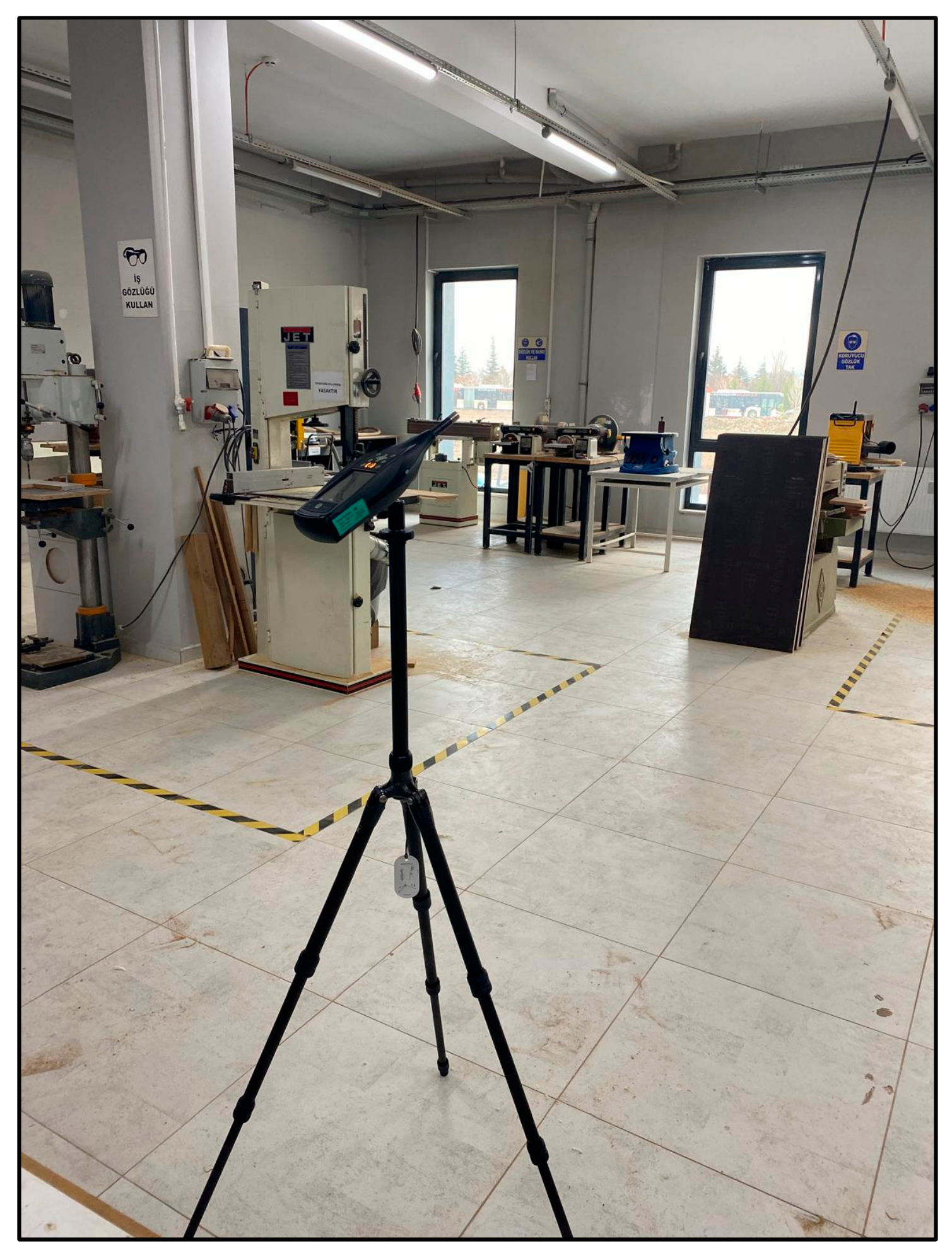
The existing acoustic assessment consisted of two distinct stages. First, the noise environment within the woodworking workshop was characterized through in-situ sound pressure level measurements (Figure 9). Second, the airborne sound insulation performance of the existing partition systems was evaluated numerically. The Rw values of the individual building elements were predicted using INSUL, while the building-scale R′w, DnT,w, and DnT,A values were calculated using Kalksandstein (KS). No in-situ sound-insulation measurements were conducted for the existing partition systems.
The field measurements showed that the woodworking machinery used for cutting, planing, drilling, and sanding operations generated high noise levels within the workshop. The measured equivalent continuous sound pressure level (LAeq) was 91.17 dB, while the maximum A-weighted sound pressure level (LAFmax), minimum A-weighted sound pressure level (LAFmin), and peak C-weighted sound pressure level (LCpeak) were 93.01 dB, 89.60 dB, and 106.96 dB, respectively. The measured one-octave band spectra indicated that the dominant noise energy was concentrated in the mid- and high frequency ranges, representing a significant airborne noise source for the adjacent office.
According to the Turkish Regulation on the Protection of Buildings Against Noise (BGKKHY), spaces with LAFmax > 75 dB are classified as High Noise (HN) environments. Accordingly, the woodworking workshop was classified as a high-noise space, whereas the adjacent office was classified as a Class II noise-sensitive room. For existing buildings, the regulation specifies a target DnT,A value of 51 dB to satisfy the Class D acoustic performance requirements between these two functional spaces.
The principal direct airborne sound transmission paths between the workshop and the office were identified as the D1 and D2 partition systems, whereas the Y1, Y3, and Y4 wall systems together with the floor and ceiling assemblies constitute the principal flanking transmission paths (Figure 10).
The theoretical airborne sound insulation performance of the building elements was calculated using the INSUL software. The analysis results showed that the aerated concrete wall systems provided relatively high airborne sound insulation performance, whereas the aluminum-framed double-glazed partition system separating the workshop and the office exhibited the lowest sound insulation performance among all investigated building elements. The calculated Rw values of all building elements are summarized in Table 4.
The Rw values obtained from the INSUL analyses were subsequently imported into the Kalksandstein (KS) software to evaluate the apparent airborne sound insulation performance at the building scale.
The calculated R′w, DnT,w, and DnT,A values indicate that the existing partition systems do not satisfy the Class D acoustic performance requirements specified in the Turkish Regulation on the Protection of Buildings Against Noise (BGKKHY) for existing buildings (Table 5). The results clearly demonstrate that the aluminum-framed glazed partition systems (D1 and D2) constitute the dominant weakness of the existing acoustic design and represent the principal airborne sound transmission path between the woodworking workshop and the office. Consequently, these partition systems were identified as the primary target for the development of the proposed acoustic design strategies.
According to the KS calculations, the existing D1 partition had predicted values of R′w = 31.8 dB, DnT,w = 34.8 dB, and DnT,A = 33.2 dB, while the corresponding predicted values for D2 were R′w = 32.3 dB, DnT,w = 35.3 dB, and DnT,A = 33.7 dB. These model-derived DnT,A values are below the minimum value of 51 dB specified by the BGKKHY for Class D acoustic performance in existing buildings. The numerical results therefore indicate that the existing glazed partition systems provide insufficient airborne sound insulation and constitute the principal weak points in the sound transmission path between the woodworking workshop and the adjacent office.

3.2.2. Evaluation of the Proposed Design

Since the existing D1 and D2 partition systems did not satisfy the required DnT,A value of 51 dB specified by the Turkish Regulation on the Protection of Buildings Against Noise (BGKKHY), alternative partition configurations were developed and their theoretical airborne sound insulation performances were re-evaluated using the INSUL software. Subsequently, the building-scale acoustic performances of the proposed configurations were assessed using the Kalksandstein (KS) software. The proposed design modifications included the redesign of the partition systems, reduction in the glazed surface area, development of alternative wall assemblies, and improvement of the door systems. The INSUL analyses predicted substantially higher Rw values for the proposed partition systems than for the existing configurations. The subsequent KS calculations similarly predicted significant increases in apparent airborne sound insulation performance at the building scale.
Alternative wall assemblies were also developed for the Y1, Y3, and Y4 walls, which constitute the principal flanking transmission paths between the woodworking workshop and the adjacent spaces. Because these walls also separate the workshop from other rooms within the Design and Application Laboratory Building, improving their sound insulation performance contributes not only to the acoustic comfort of the office but also to reducing noise transmission to surrounding spaces. The existing and proposed material configurations of the Y1, Y3, and Y4 wall systems are presented in Table 6.
Although the floor and ceiling assemblies contribute to flanking sound transmission, their existing airborne sound insulation performances were found to be satisfactory. Therefore, no modifications were proposed for these building elements.
The existing and proposed layer configurations of the D1 and D2 partition systems are presented in Table 7 and Table 8, respectively.
The proposed D1 glazing system was modelled using the pane thicknesses, material properties, and cavity dimensions listed in Table 7. Material properties were assigned from the INSUL material database, while the framing and perimeter sealing were treated according to the modelling assumptions described in Section 2.4.2.
For the proposed D2 partition system, the wall assembly was designed using the same material configuration as that proposed for the D1, Y1, Y3, and Y4 wall systems. However, unlike the D1 partition, the D2 partition requires an access door to maintain functional circulation between the office and the workshop. Therefore, a double-door system consisting of two consecutive doors, each measuring 0.9 m × 2.1 m, was incorporated into the proposed design. The existing and proposed material layer configurations of the D2 wall–door assembly are presented in Table 8. The acoustic properties of the proposed door assembly were defined using the material configuration presented in Table 8, with the corresponding material properties assigned from the INSUL material database. No additional leakage associated with imperfect door closure, perimeter gaps, or seal deterioration was introduced into the numerical model. Therefore, the predicted performance assumes properly fitted door assemblies with continuous perimeter sealing.
The proposed partition system was developed not only to improve airborne sound insulation performance but also to preserve the required visual connectivity and functional accessibility between the production area and the office. Accordingly, the proposed configuration represents a balanced design solution that simultaneously addresses acoustic performance, operational requirements, and practical applicability.
Based on the material configurations presented in Table 7 and Table 8, the theoretical airborne sound insulation performance of the redesigned D1 and D2 partition systems was evaluated using INSUL. For the D1 partition system, the calculated Rw values were 67 dB for the proposed wall assembly and 63 dB for the proposed glazed section. For the D2 partition system, the calculated Rw values were 67 dB for the wall assembly and 56 dB for the door assembly.
Since both D1 and D2 partition systems consist of more than one building element (i.e., wall–window and wall–door assemblies), they were modeled as composite partitions in the Kalksandstein (KS) analyses (Figure 11 and Figure 12). Accordingly, the overall sound reduction performance of the composite partitions was calculated using an area-weighted sound transmission coefficient approach, consistent with the principles applied to separating elements in building-acoustic calculations [46]. The equivalent sound reduction index of each composite partition was calculated from the area-weighted sound transmission coefficients of its constituent elements as follows:
τ = j = 1 n Sj S 10 Rj 10
  • τ is the average sound transmission coefficient of the composite partition;
  • Rj is the sound reduction index of the jth building element (dB);
  • Sj is the surface area of the jth building element (m2);
  • S is the total surface area of the composite partition (m2);
  • n is the number of building elements forming the composite partition.
where τ is the area-weighted sound transmission coefficient of the composite partition, Rj is the sound reduction index of the jth constituent element (dB), Sj is the surface area of the jth constituent element (m2), S is the total surface area of the composite partition (m2), and n is the number of constituent elements.
After determining the average sound transmission coefficient ( τ ¯ ), the equivalent sound reduction index (R) of the composite partition was calculated using the following relationship:
R = −10log10(τ) or τ = 10R10
Using this procedure, the composite airborne sound insulation performance of the proposed partition systems was determined as Rw = 66.4 dB for the D1 partition and Rw = 64.2 dB for the D2 partition.
These calculated results indicate that both proposed composite partition systems are predicted to provide substantially higher airborne sound insulation performance than the existing configurations and to satisfy the target sound insulation requirements prior to the building-scale KS analyses.
Figure 11. KS model of the proposed D1 partition system between the woodworking workshop and the office.
Buildings 16 03746 g011
Figure 12. KS analysis model of the proposed D2 partition system between the woodworking workshop and the office.
Buildings 16 03746 g012
The 1.50 × 1.50 m glazed opening was positioned at the horizontal center of the D1 partition, with a 40 cm parapet height, to provide an appropriate field of view of the workshop area for both seated and standing users in the office. Visual connectivity was classified as preserved when the proposed configuration retained a transparent glazed separation, an unobstructed sightline from the office toward the production area, and the functional ability to visually supervise the main workshop activities.
The Rw values obtained from the proposed Y1, Y3, Y4, D1, and D2 partition systems were incorporated into the Kalksandstein (KS) model to evaluate the building-scale acoustic performance. For the proposed D1 composite partition, the KS-calculated values were R′w = 55.9 dB, DnT,w = 58.9 dB, and DnT,A = 57.3 dB. Similarly, the KS-calculated values for the proposed D2 composite partition were R′w = 55.7 dB, DnT,w = 58.7 dB, and DnT,A = 57.1 dB. Since the required DnT,A value specified by the Turkish Regulation on the Protection of Buildings Against Noise (BGKKHY) for existing buildings is 51 dB, the numerical results indicate that both proposed partition systems are predicted to satisfy the Class D acoustic performance criterion. A comparative summary of the acoustic performance of the existing and proposed building elements is presented in Table 9.
The comparison indicates that the aluminum-framed glazed partition systems (D1 and D2) are predicted to constitute the dominant airborne sound transmission path governing the acoustic performance of the office. Although the opaque wall, floor, and ceiling systems already provide relatively high sound insulation performance, the overall acoustic performance of the building is controlled by the weakest partition elements. This finding indicates that, within the adopted numerical modelling framework, improving the acoustically weakest transmission path is predicted to be more effective than further enhancing building elements that already exhibit adequate sound insulation performance.
Among the proposed design modifications, the D1 and D2 partition systems showed the largest predicted increases in acoustic performance. The KS-predicted DnT,A value increased by 24.1 dB for D1, from 33.2 dB to 57.3 dB, and by 23.4 dB for D2, from 33.7 dB to 57.1 dB. Accordingly, the predicted DnT,A values of both proposed partition systems exceed the Class D acoustic performance criterion specified in the BGKKHY for existing buildings.
Although the proposed improvements to the Y1, Y3, and Y4 wall systems increased their laboratory sound insulation performance, their contribution to the overall building-scale acoustic performance was relatively limited compared with the improvements achieved for the D1 and D2 partition systems. Therefore, the results indicate that prioritizing the improvement of the critical transmission paths provides a substantially more efficient and cost-effective design strategy than uniformly increasing the sound insulation performance of all building elements. Although the predicted improvements for D1 and D2 are substantial, these values should be interpreted in relation to the assumptions adopted in the numerical models. The predicted performance is particularly sensitive to the acoustic properties of the glazing and door assemblies, frame construction, perimeter sealing, junction conditions, and the representation of flanking transmission. In practice, deviations in material properties, imperfect sealing, installation tolerances, or workmanship may reduce the sound insulation achieved in situ. Therefore, the calculated increases of +24.1 dB for D1 and +23.4 dB for D2 represent predicted improvements under the adopted modelling assumptions rather than guaranteed post-retrofit performance.
Considering the acoustic performance, preservation of visual connectivity, implementation feasibility, and construction cost together, the proposed D1 and D2 partition systems were identified as the most appropriate design solution. These findings indicate that, for the investigated case, focusing on the dominant airborne sound transmission paths is predicted to provide greater acoustic improvement than uniformly increasing the sound insulation performance of all building elements. Accordingly, the proposed methodology provides a practical and systematic design approach that can be applied to industrial buildings with similar functional and operational requirements.


3.3. Receiver Control

Within the scope of the receiver control assessment, the interior layout and surface materials of the office were re-evaluated to identify practical measures for improving acoustic comfort without affecting the required visual connection with the woodworking workshop. The office functions as a private workspace used for planning, coordination, supervision, and administrative activities related to the production process. Consequently, the office must simultaneously provide an appropriate acoustic environment and maintain direct visual communication with the production area.
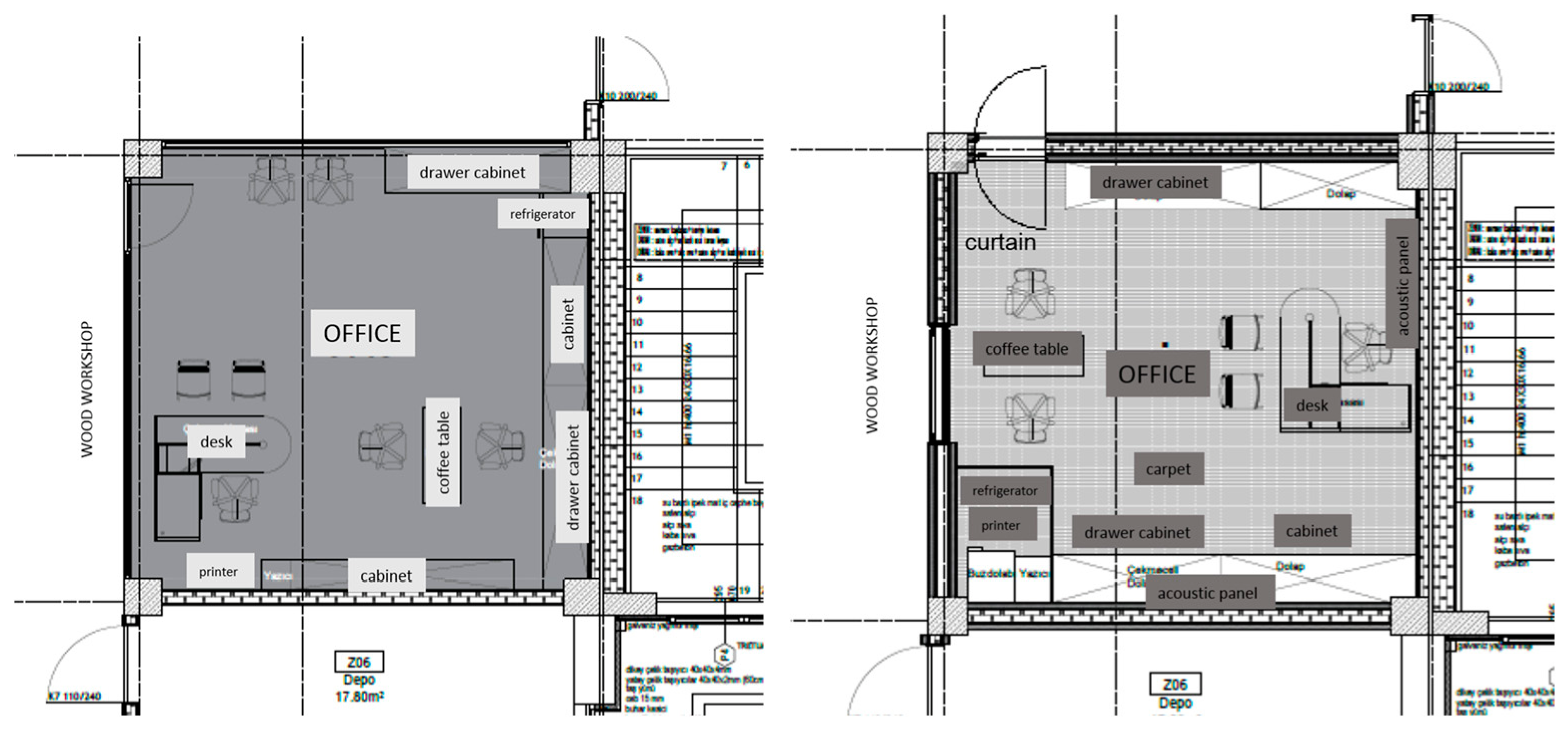
The existing office layout consists of a workstation, visitor seating, storage cabinets, a refrigerator, a coffee machine, and printing equipment. The assessment revealed that the workstation is positioned directly opposite the glazed partition facing the workshop, resulting in the highest exposure to airborne noise transmitted from the production area. Furthermore, secondary noise sources, including the printer, photocopier, refrigerator, and coffee machine, are distributed throughout the office, increasing the background noise level within the workspace.
Based on the spatial assessment, relocating the workstation farther from the glazed partition while maintaining visual supervision of the workshop was identified as the most appropriate layout strategy. In addition, grouping secondary noise-generating equipment within a dedicated service zone would reduce unnecessary background noise in the primary working area.
The evaluation of the interior finishes indicated that the floor, walls, and ceiling are predominantly composed of hard, reflective materials. Apart from a cork notice board positioned behind the workstation, no sound-absorbing surfaces are currently provided within the office. Consequently, reflected sound is expected to increase reverberation and reduce speech intelligibility during routine office activities.
Accordingly, the application of carpet flooring, porous sound-absorbing wall panels, suspended acoustic ceiling systems, and sound-absorbing partition screens between the workstation and office equipment was identified as an effective receiver-control strategy. These measures are expected to improve the acoustic environment without compromising the required visual connection between the workshop and the office.
Overall, the receiver-control measures should be regarded as complementary to the proposed source-control and transmission-path-control strategies (Figure 13). While they cannot compensate for insufficient sound insulation of the separating partition systems, they contribute to improving the overall acoustic comfort of the office by reducing internal noise levels and improving speech conditions.

4. Discussion

4.1. Key Design Factors Governing Acoustic Performance

One of the principal findings of this study is that the acoustic performance of office spaces in small-scale industrial buildings is governed not only by the magnitude of the noise source but also by the spatial organization of the building and the acoustic characteristics of the partition systems. The combined evaluation of field measurements, INSUL simulations, and Kalksandstein (KS) analyses demonstrated that the aluminum-framed glazed partition systems separating the woodworking workshop from the office constitute the dominant airborne sound transmission path. In contrast, the opaque wall, floor, and ceiling systems exhibited relatively high sound insulation performance and therefore did not represent the critical elements controlling the overall acoustic performance of the building. These findings are consistent with previous studies highlighting the importance of partition systems, junction details, and flanking transmission in determining the apparent airborne sound insulation performance of buildings [22,23,24,45,46].
These findings confirm the well-established “weakest element” principle in building acoustics, whereby the overall sound insulation performance of a building is determined by the building element with the lowest sound insulation rather than by the highest-performing components [23,24,45]. Consequently, improving only the sound insulation performance of opaque wall systems is insufficient. Partition systems designed to maintain visual connectivity should also provide acoustic performance comparable to that of the surrounding opaque building elements. Similar observations have been reported for glazed partition systems, where the acoustic performance depends not only on the glazing itself but also on the frame construction, sealing quality, and installation details [21,35,45].
The proposed design strategies further support this conclusion. The modifications applied to the D1 and D2 partition systems resulted in substantially greater improvements in building-scale acoustic performance than any additional enhancement of the already high-performing opaque wall systems. These results indicate that, for the investigated case, improving the critical airborne sound transmission paths is predicted to be more effective than further enhancing the already high-performing opaque wall systems, consistent with established building-acoustic principles concerning the influence of separating elements and transmission paths on overall sound insulation performance [45,46].

4.2. Balancing Visual Connectivity and Acoustic Comfort

Direct visual connectivity between production areas and office or control spaces is an essential functional requirement in many industrial buildings. Maintaining visual supervision facilitates production monitoring, quality control, and occupational safety. Consequently, glazed partition systems are commonly employed to preserve visual continuity between these spaces. However, this requirement inevitably creates a conflict between visual accessibility and acoustic performance. Previous studies have similarly emphasized that glazed partition systems often require a compromise between architectural transparency and acoustic privacy, particularly in workplaces where both supervision and noise control are critical [21,23,35].
A similar situation was observed in the investigated building, where maintaining direct visual connectivity between the woodworking workshop and the office significantly restricted the possibility of modifying the spatial organization. Conventional noise-control strategies, such as introducing buffer spaces or increasing the separation distance between production and office areas, were therefore not considered feasible. Instead, the numerical analyses indicated that substantial acoustic improvements could be obtained through the redesign of the partition systems while preserving the required visual relationship. The identification of the weakest separating element as a controlling factor in overall airborne sound-insulation performance is consistent with established principles of building acoustics and is not, by itself, a novel finding of this study. The case-specific contribution lies instead in addressing the acoustically critical D1 and D2 partition systems while retaining their functional role in maintaining visual supervision between the woodworking workshop and the office. Rather than eliminating the glazed connection or spatially separating the two functions, the proposed retrofit strategy improves the predicted acoustic performance of these critical elements while preserving the required visual relationship. This finding supports previous research indicating that improvements in glazing systems, framing details, and sealing performance can substantially enhance acoustic performance without compromising visual connectivity [21,35,45].
These findings demonstrate that visual accessibility and acoustic comfort should not be considered conflicting design objectives but rather complementary criteria that must be optimized simultaneously. The proposed approach may provide a useful basis for future investigations in control rooms, laboratories, maintenance facilities, and other industrial settings where continuous visual supervision is operationally required; however, its applicability to such contexts requires further validation.

4.3. Contribution of Numerical Analyses to Design Decisions

The combined use of field measurements, INSUL simulations, and Kalksandstein (KS) analyses enabled a comprehensive assessment of acoustic performance at both the building-element and building scales. While INSUL predicted the laboratory airborne sound insulation performance of individual building elements, the KS analyses incorporated room geometry, junction details, and flanking sound transmission to predict the apparent airborne sound insulation performance at the building scale by accounting for room geometry, junction details, and flanking transmission. This combined approach is consistent with current building acoustics practice, which recommends integrating laboratory-based predictions with building-scale evaluation methods to obtain more realistic estimates of in-situ acoustic performance [45,46,48,49,51].
The complementary use of these numerical methods made it possible to distinguish between element-level predicted performance and building-scale predicted performance, thereby indicating that acoustic performance is influenced not only by the sound insulation properties of individual building elements but also by junction details, room geometry, and indirect transmission paths. Consequently, alternative design solutions could be evaluated numerically before implementation, providing a reliable basis for performance-based design decisions. Similar observations have been reported by Hopkins [25] and are reflected in the calculation procedures of EN ISO 12354-1 [46], which emphasize the importance of flanking transmission and structural junctions in determining the apparent airborne sound insulation of buildings.
These findings highlight that effective acoustic design requires an integrated evaluation of all sound transmission mechanisms at the building scale rather than focusing exclusively on the acoustic properties of individual materials. Accordingly, the combined use of field measurements and complementary numerical prediction tools provides a practical and reliable framework for supporting acoustic design and retrofit decisions in industrial buildings [22,45,46].

4.4. Contribution to the Study

Previous studies on industrial noise have primarily focused on workers’ noise exposure, machine-generated noise, or the sound-insulation performance of individual building components. Studies addressing acoustically sensitive office spaces that must retain direct visual connectivity with adjacent noisy production areas remain comparatively limited.
The contribution lies in the coordinated application of established acoustic assessment and prediction approaches to a retrofit problem in which acoustic improvement and the preservation of visual supervision are treated as simultaneous design requirements.
In the investigated case, this approach enabled the acoustically critical D1 and D2 partition systems to be identified and retrofit alternatives to be evaluated without eliminating the glazed connection between the woodworking workshop and the office. The analysis demonstrates how element-level predictions and building-scale calculations can support decisions regarding which building components should be prioritized when the acoustically weakest elements also perform an essential architectural and operational function.
Accordingly, the study provides a case-based decision framework for addressing similar acoustic–functional conflicts in industrial buildings. Its applicability beyond the investigated facility should, however, be interpreted cautiously because the present study is based on a single woodworking facility, considers airborne sound transmission only, and does not include post-retrofit field verification. Further studies involving different industrial activities, spatial configurations, and post-construction measurements are required to assess the broader applicability of the proposed approach.

4.5. Study Limitations and Future Research

This study was conducted using a single industrial case study, and the assessment was limited to airborne sound transmission. Structure-borne vibration, impact sound transmission, and the influence of different manufacturing processes with varying noise characteristics were beyond the scope of the present investigation. Furthermore, the proposed design alternatives were evaluated through numerical simulations using INSUL and Kalksandstein (KS), whereas experimental validation through post-implementation field measurements was not included. Accordingly, the findings should be interpreted within the limitations of prediction-based acoustic assessment methods and the investigated case-specific conditions [22,45,46]. Furthermore, although the glazed opening dimensions and its vertical and horizontal positioning were defined quantitatively, visual connectivity was not evaluated using a formal quantitative visual-performance index. Future studies could incorporate quantitative visibility or sightline-based indicators to further investigate the interaction between acoustic performance and visual connectivity (Figure 14).
Future research should investigate similar acoustic design strategies in industrial buildings representing different manufacturing sectors and operational conditions. Particular attention should be given to the interaction between airborne and structure-borne sound transmission, as well as to the experimental validation of the proposed design solutions following full-scale implementation. In addition, further studies incorporating cost–performance optimization, life-cycle assessment, and the acoustic behavior of alternative glazing and partition systems would contribute to the development of more comprehensive design guidelines for industrial buildings.
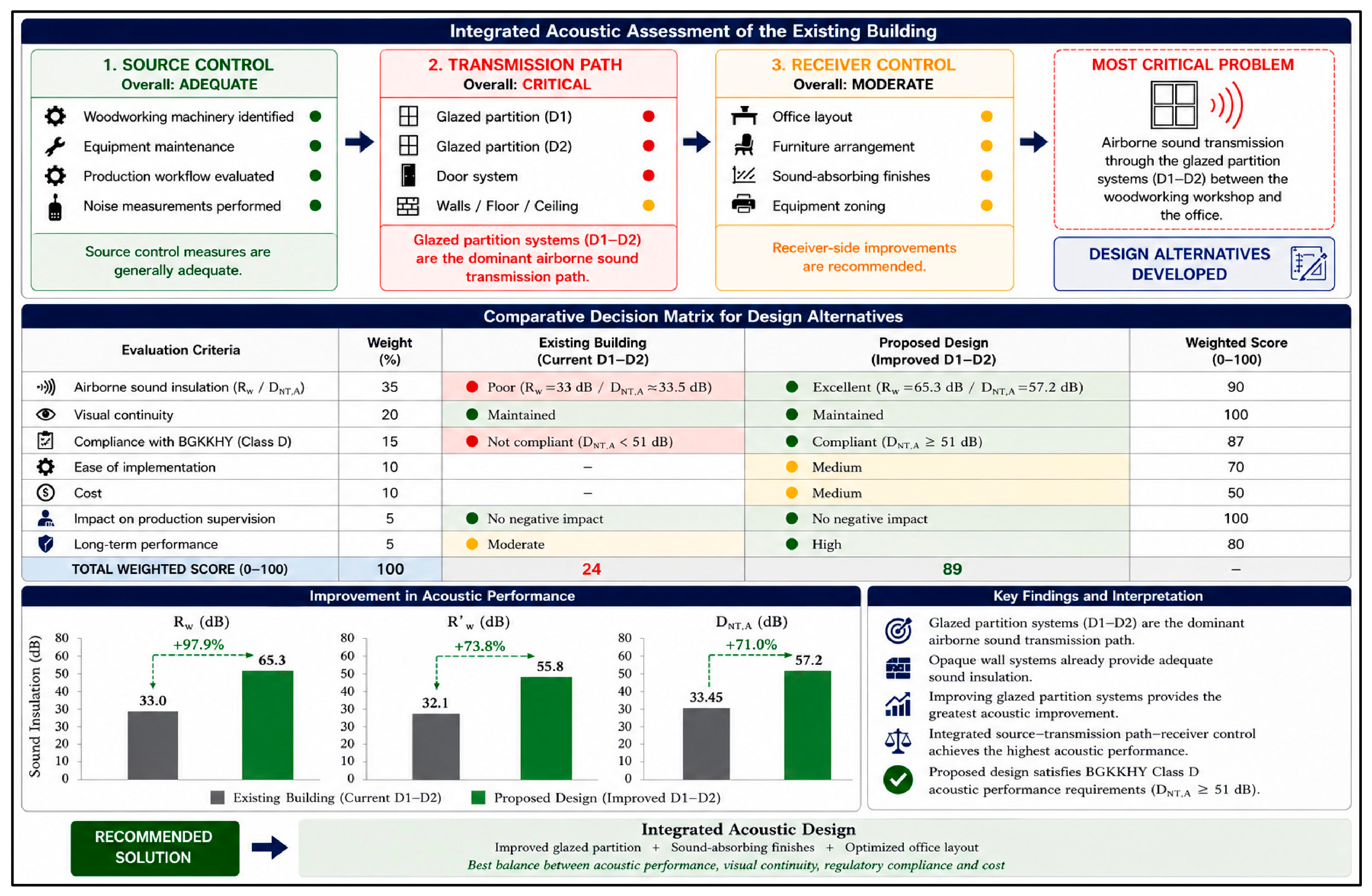
Figure 15 presents a comprehensive evaluation of the proposed design alternatives by considering not only acoustic performance but also constructability, cost, and functional requirements. The comparison demonstrates that the solution providing the highest sound insulation performance is not necessarily the most appropriate design option. Although opaque wall systems can achieve superior sound insulation values, they cannot satisfy the functional requirement of maintaining visual connectivity between the workshop and the office. Consequently, the proposed D1 and D2 partition systems provide a feasible design option, as their predicted acoustic performance meets the target criterion while preserving visual supervision and maintaining practical applicability.
Based on the comparative evaluation, the proposed D1 and D2 partition systems were identified as feasible design options because their predicted acoustic performance met the target criterion while maintaining visual connectivity and practical feasibility. Although the improvements applied to the Y1–Y3–Y4 wall system enhanced its laboratory sound insulation performance, their contribution to the overall building-scale acoustic performance was limited. Consequently, these improvements were not considered a priority solution from a cost–performance perspective. This finding is consistent with the building acoustics principle that improvements should primarily target the dominant sound transmission paths rather than uniformly increasing the sound insulation of all building elements [22,45,46].
These findings demonstrate that acoustic retrofit strategies for industrial buildings should not be based solely on the sound insulation performance of individual building elements. Instead, engineering decisions should be guided by a balanced consideration of acoustic performance, functional requirements, visual connectivity, implementation feasibility, and cost. This integrated evaluation provides a practical decision-making framework for selecting the most effective acoustic design solutions in industrial buildings. The predicted performance of the proposed D1 and D2 systems is subject to uncertainty associated with the assumptions adopted in the numerical models. In particular, the predicted sound insulation may be sensitive to the acoustic properties of the glazing and door assemblies, frame construction, perimeter sealing, junction conditions, workmanship, and the representation of flanking transmission. Variations in these parameters or installation conditions may result in differences between the predicted and actual in-situ performance. Therefore, the reported values should be interpreted as predictions under the adopted modelling assumptions rather than guaranteed post-retrofit performance. Future studies should include sensitivity analyses and post-construction field measurements to quantify these effects and verify the predicted performance.
The broader applicability of the findings is limited by the case-study design. The investigation was conducted in a single woodworking facility and focused exclusively on airborne sound transmission. In addition, the short-term measurement protocol does not capture the full temporal variability associated with all possible machine combinations and operating cycles; therefore, the measured levels should be interpreted as representative of the monitored normal operating conditions rather than as a full-shift characterization of occupational noise exposure. Furthermore, the proposed retrofit configurations were evaluated numerically and were not implemented and verified through post-retrofit field measurements. Therefore, further case studies involving different industrial activities and building configurations, together with post-construction acoustic measurements, are required before broader generalization of the findings can be established.

5. Conclusions

This study evaluated the airborne sound insulation performance of office units located within small-scale industrial buildings where visual connectivity with production spaces must be maintained. The Design and Application Laboratory Building of Eskişehir Technical University was used as a case study. Field measurements were used to characterize the existing noise environment within the woodworking workshop, whereas the airborne sound insulation performance of the existing and proposed partition systems was evaluated numerically using INSUL and Kalksandstein (KS). Based on the identified deficiencies, alternative design solutions were developed and their predicted acoustic performance was quantitatively evaluated.
The findings demonstrate that the acoustic performance of industrial office spaces is governed not only by the characteristics of the noise source but also by the sound transmission path, the acoustic performance of partition systems, and the spatial organization of the building. The analyses consistently identified the aluminum-framed glazed partition as the weakest component in the sound transmission path. Following the numerical redesign of the partition systems while preserving the required visual connection between the office and the production area, the KS-predicted DnT,A values increased from 33.2 dB to 57.3 dB for Partition D1 and from 33.7 dB to 57.1 dB for Partition D2. These numerical results indicate that the proposed configurations are predicted to satisfy the Class D airborne sound insulation requirements specified in the Turkish Regulation on the Protection of Buildings Against Noise. However, post-retrofit field measurements would be required to verify actual in-situ compliance.
Beyond these case-specific improvements, the principal contribution of this study is the development of an integrated acoustic design framework for office units in small-scale industrial buildings. Rather than evaluating acoustic performance solely through the sound insulation of individual building components, the proposed framework combines source control, transmission path control, and receiver control within a unified design process. This hierarchical approach enables architectural planning, spatial organization, partition design, and interior layout decisions to be considered together from the early design stages, allowing acoustic performance to be addressed systematically while maintaining operational and visual requirements.
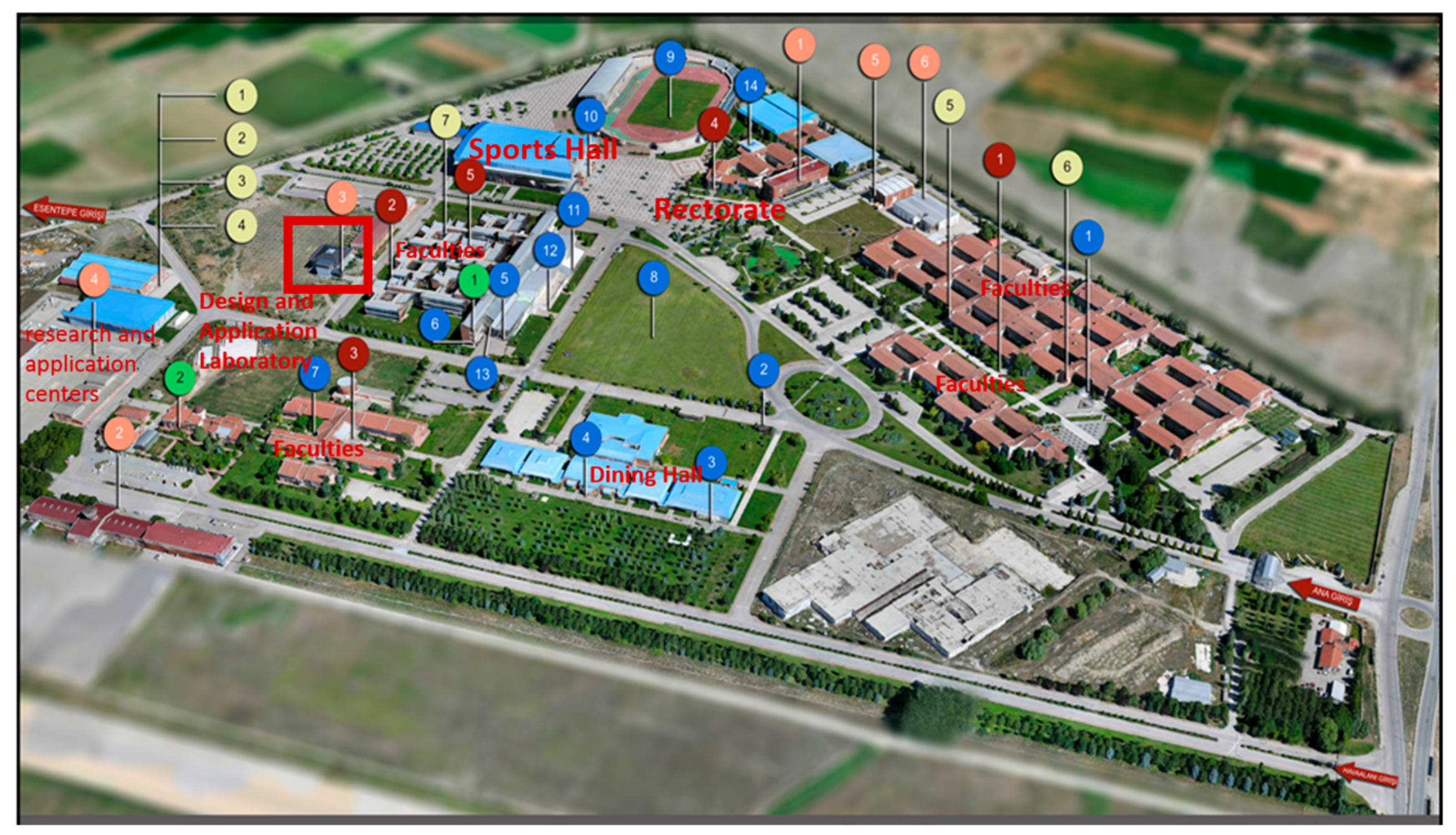
Another contribution of the study is the translation of this framework into a practical set of design strategies supported by quantitative performance assessment. By integrating field measurements with numerical analyses, the proposed methodology provides designers with a structured procedure for identifying dominant sound transmission paths, evaluating alternative design solutions, and assessing their predicted effectiveness before implementation (Table 10). Therefore, the proposed approach may provide a useful basis for acoustic design and retrofit decision-making in industrial buildings with similar functional requirements; however, its broader applicability requires validation through additional case studies and post-retrofit field measurements.
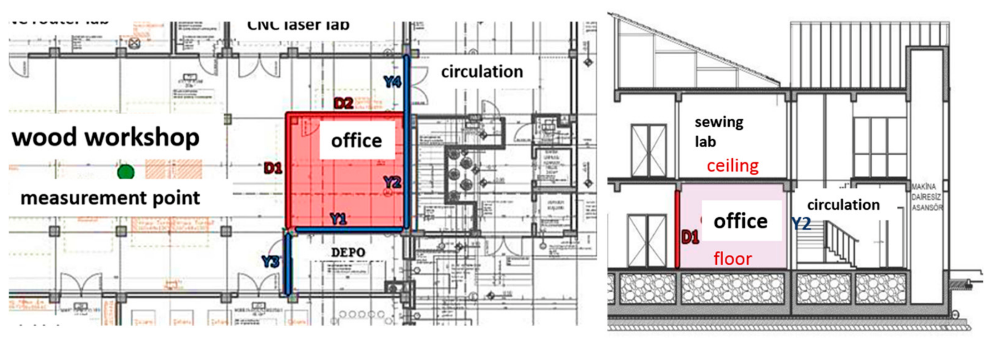
The study is limited to a single case study and considers only airborne sound transmission. Future research should validate the proposed framework in different industrial sectors and building configurations, incorporate structure-borne sound and vibration transmission, and experimentally evaluate the long-term performance of the proposed design solutions. Such studies would further improve the applicability and generalizability of the proposed framework.

Author Contributions

Conceptualization, G.A.G.; methodology, G.A.G. and M.İ.; software, M.İ.; validation, G.A.G. and M.İ.; formal analysis, G.A.G. and M.İ.; investigation, G.A.G. and M.İ.; resources, G.A.G. and M.İ.; data curation, G.A.G. and M.İ.; writing—original draft preparation, G.A.G.; writing—review and editing, G.A.G.; visualization, G.A.G.; supervision, G.A.G.; project administration, G.A.G. All authors have read and agreed to the published version of the manuscript.

Funding

This research received no external funding.

Data Availability Statement

Dataset available on request from the authors.

Acknowledgments

This study was derived from the master’s thesis of the first author, completed under the supervision of the second author. The authors would like to express their sincere gratitude to the Dean’s Office of the Faculty of Architecture and Design at Eskişehir Technical University and its staff for their valuable support. The authors gratefully acknowledge SUBERA, the official distributor of INSUL software in Türkiye, for their support and assistance.

Conflicts of Interest

The authors declare no conflicts of interest.

References

  1. Basner, M.; Babisch, W.; Davis, A.; Brink, M.; Clark, C.; Janssen, S.; Stansfeld, S. Auditory and non-auditory effects of noise on health. Lancet 2014, 383, 1325–1332. [Google Scholar] [CrossRef] [Scilit]
  2. Atmaca, E.; Peker, I.; Altın, A. Industrial noise and its effects on humans. Pol. J. Environ. Stud. 2005, 14, 721–726. [Google Scholar]
  3. World Health Organization Regional Office for Europe. Environmental Noise Guidelines for the European Region; WHO Regional Office for Europe: Copenhagen, Denmark, 2018; 181p, Available online: https://www.who.int/europe/publications/i/item/9789289053563 (accessed on 9 September 2026).
  4. European Environment Agency (EEA). Environmental Noise in Europe—2020; EEA Report No. 22/2019; European Environment Agency: Copenhagen, Denmark, 2020; 104p, Available online: https://www.eea.europa.eu/publications/environmental-noise-in-europe (accessed on 9 September 2026).
  5. Themann, C.L.; Masterson, E.A. Occupational noise exposure: A review of its effects, epidemiology, and impact with recommendations for reducing its burden. J. Acoust. Soc. Am. 2019, 146, 3879–3905. [Google Scholar] [CrossRef] [Scilit]
  6. Zeng, Y.P.; Juang, Y.J.; Yiin, L.M. Modeling of woodworkers’ exposure to occupational noises by integrating frequency spectra generated by power tools: A pilot study. Appl. Sci. 2020, 10, 6453. [Google Scholar] [CrossRef] [Scilit]
  7. ISO 1996-1:2016; Acoustics—Description, Measurement and Assessment of Environmental Noise—Part 1: Basic Quantities and Assessment Procedures. International Organization for Standardization: Geneva, Switzerland, 2016.
  8. Chatillon, J. Influence of source directivity on noise levels in industrial halls: Simulation and experiments. Appl. Acoust. 2007, 68, 682–698. [Google Scholar] [CrossRef] [Scilit]
  9. Bozkurt, T.S. Preparation of industrial noise mapping and improvement of environmental quality. Curr. Pollut. Rep. 2021, 7, 325–343. [Google Scholar] [CrossRef] [Scilit]
  10. Casas, W.J.P.; Cordeiro, E.P.; Mello, T.C.; Zannin, P.H.T. Noise mapping as a tool for controlling industrial noise pollution. J. Sci. Ind. Res. 2014, 73, 262–266. [Google Scholar]
  11. Rikhotso, O.; Harmse, J.L.; Engelbrecht, J.C. Noise sources and control, and exposure groups in chemical manufacturing plants. Appl. Sci. 2019, 9, 3523. [Google Scholar] [CrossRef] [Scilit]
  12. Guarnaccia, C.; Mastorakis, N.E.; Quartieri, J. Noise sources analysis in a wood manufacturing company. Int. J. Mech. 2013, 7, 37–44. [Google Scholar]
  13. Everest, F.A.; Pohlmann, K.C. Master Handbook of Acoustics, 7th ed.; McGraw-Hill Education: New York, NY, USA, 2021. [Google Scholar]
  14. Bolaji, B.O.; Olanipekun, M.U.; Adekunle, A.A.; Adeleke, A.E. An analysis of noise and its environmental burden on the example of Nigerian manufacturing companies. J. Clean. Prod. 2018, 172, 1800–1806. [Google Scholar] [CrossRef] [Scilit]
  15. Tomozei, C.; Astolfi, A.; Nedeff, V.; Lazar, G. Noise sources characterization inside and outside a factory. Environ. Eng. Manag. J. 2012, 11, 701–708. [Google Scholar] [CrossRef] [Scilit]
  16. Seddigh, A.; Berntson, E.; Jönsson, F.; Danielson, C.B.; Westerlund, H. The effect of noise absorption variation in open-plan offices: A field study with a cross-over design. J. Environ. Psychol. 2015, 44, 34–44. [Google Scholar] [CrossRef] [Scilit]
  17. Leder, S.; Newsham, G.R.; Veitch, J.A.; Mancini, S.; Charles, K.E. Effects of office environment on employee satisfaction: A new analysis. Build. Res. Inf. 2016, 44, 34–50. [Google Scholar] [CrossRef] [Scilit]
  18. Bruyninckx, J. Tuning the office sound masking and the architectonics of office work. Sound Stud. 2023, 9, 64–84. [Google Scholar] [CrossRef] [Scilit]
  19. Fry, A.T.; Sturz, D.H. Noise control in heating, ventilating, and air conditioning systems. In Noise and Vibration Control Engineering: Principles and Applications, 2nd ed.; Vér, I.L., Beranek, L.L., Eds.; John Wiley & Sons: Hoboken, NJ, USA, 2006. [Google Scholar] [CrossRef] [Scilit]
  20. Bliūdžius, R.; Miškinis, K.; Buhagiar, V.; Banionis, K. Sound insulation of façade element with triple IGU. Buildings 2022, 12, 1239. [Google Scholar] [CrossRef] [Scilit]
  21. Dulak, L.; Nowoświat, A. Effect of window structure and mounting on sound insulation: A laboratory-based study. Sustainability 2025, 17, 6892. [Google Scholar] [CrossRef] [Scilit]
  22. Fahy, F.J.; Gardonio, P. Sound and Structural Vibration: Radiation, Transmission and Response, 2nd ed.; Academic Press: Oxford, UK, 2007. [Google Scholar]
  23. Mehta, M.; Johnson, J.; Rocafort, J. Architectural Acoustics: Principles and Design; Prentice Hall: Upper Saddle River, NJ, USA, 1999. [Google Scholar]
  24. Egan, M.D. Architectural Acoustics; J. Ross Publishing: Plantation, FL, USA, 2007. [Google Scholar]
  25. Hopkins, C. Sound Insulation; Routledge: London, UK, 2012. [Google Scholar] [CrossRef] [Scilit]
  26. ISO 11690-1:2020; Acoustics—Recommended Practice for the Design of Low-Noise Workplaces Containing Machinery—Part 1: Noise Control Strategies. International Organization for Standardization: Geneva, Switzerland, 2020.
  27. Özdemir, M.; Albayrak, S. Occupational safety and hidden risks in a furniture factory: A comprehensive assessment of hazards related to noise, lighting, thermal comfort, and dust exposure. BioResources 2024, 19, 9259–9270. [Google Scholar] [CrossRef] [Scilit]
  28. Ministry of Environment and Urbanization of the Republic of Türkiye. Regulation on the Protection of Buildings Against Noise (BGKKHY); Official Gazette No. 30082; Official Gazette of the Republic of Türkiye: Ankara, Türkiye, 2017.
  29. Şimşek, O. Evaluation of noise control in industrial buildings through simulations. Adv. Civ. Archit. Eng. 2025, 16, 67–82. [Google Scholar] [CrossRef] [Scilit]
  30. Serin, H.; Şahin, Y.; Durgun, M. Noise analyses in small-scale furniture enterprises. Düzce Univ. Fac. For. J. For. 2013, 9, 1–8. [Google Scholar]
  31. Untuç, B.; Yüğrük Akdağ, N. Noise control in buildings: Evaluations within the scope of a case study. Artium 2017, 5, 11–21. [Google Scholar]
  32. Keskin, O.; Duran, F.N. Optimization of building envelope in terms of sound insulation and thermal performance—Case study: Antalya 100. Yıl Boulevard. El-Cezeri 2022, 9, 1157–1169. [Google Scholar] [CrossRef] [Scilit]
  33. Eskişehir Technical University. Campus Map. Available online: https://www.eskisehir.edu.tr/Icerik/Detay/kampus-haritasi#lg=1&slide=0 (accessed on 22 July 2026).
  34. Hongisto, V. A model predicting the effect of speech of varying intelligibility on work performance. Indoor Air 2005, 15, 458–468. [Google Scholar] [CrossRef] [Scilit]
  35. Harvey, C.; Jurdic, V.; Pollock, C.; Boning, W. The cost of transparency: Balancing acoustic, financial, and sustainability considerations for glazed office partitions. J. Acoust. Soc. Am. 2024, 155, A20. [Google Scholar] [CrossRef] [Scilit]
  36. Murphy, E.; King, E.A. Environmental Noise Pollution: Noise Mapping, Public Health, and Policy; Elsevier: Amsterdam, The Netherlands, 2014. [Google Scholar] [CrossRef] [Scilit]
  37. Kang, J.; Schulte-Fortkamp, B. (Eds.) Soundscape and the Built Environment; CRC Press: Boca Raton, FL, USA, 2016. [Google Scholar]
  38. İnce, M. Noise Control in Office Units Located in Small-Scale Industrial Buildings: A Case Study of a Woodworking Workshop. Master’s Thesis, Eskişehir Technical University, Eskişehir, Türkiye, 2026. [Google Scholar]
  39. Newman, J.S.; Beattie, K.R. Aviation Noise Effects; FAA Report No. FAA-EE-85-2; Federal Aviation Administration: Washington, DC, USA, 1985.
  40. Haka, M.; Haapakangas, A.; Keränen, J.; Hakala, J.; Keskinen, E.; Hongisto, V. Performance effects and subjective disturbance of speech in acoustically different office types—A laboratory experiment. Indoor Air 2009, 19, 454–467. [Google Scholar] [CrossRef] [Scilit]
  41. Haapakangas, A.; Hongisto, V.; Hyönä, J.; Kokko, J.; Keränen, J. Effects of unattended speech on performance and subjective distraction: The role of acoustic design in open-plan offices. Appl. Acoust. 2014, 86, 1–16. [Google Scholar] [CrossRef] [Scilit]
  42. Vér, I.L.; Beranek, L.L. (Eds.) Noise and Vibration Control Engineering: Principles and Applications, 2nd ed.; John Wiley & Sons: Hoboken, NJ, USA, 2005. [Google Scholar]
  43. Mikaeil, R.; Piri, M.; Shaffiee Haghshenas, S.; Careddu, N.; Hashemolhosseini, H. An experimental-intelligent method to predict noise value of drilling in dimension stone industry. J. Min. Environ. 2022, 13, 693–713. [Google Scholar] [CrossRef]
  44. Wegener, K.; Bleicher, F.; Heisel, U.; Hoffmeister, H.W.; Möhring, H.C. Noise and vibrations in machine tools. CIRP Ann. 2021, 70, 611–633. [Google Scholar] [CrossRef] [Scilit]
  45. Long, M. Architectural Acoustics, 2nd ed.; Academic Press: Oxford, UK, 2014. [Google Scholar]
  46. EN ISO 12354-1:2017; Building Acoustics—Estimation of Acoustic Performance of Buildings from the Performance of Elements—Part 1: Airborne Sound Insulation Between Rooms. International Organization for Standardization: Geneva, Switzerland, 2017.
  47. TS EN ISO 9612:2009; Acoustics—Determination of Occupational Noise Exposure—Engineering Method. Turkish Standards Institution (TSE): Ankara, Türkiye, 2009.
  48. Marshall Day Acoustics. INSUL Version 6.2 User Guide; Marshall Day Acoustics Ltd.: Auckland, New Zealand, 2022. [Google Scholar]
  49. Craik, R.J.M. Sound Transmission through Buildings Using Statistical Energy Analysis; Gower Publishing: Aldershot, UK, 1996. [Google Scholar]
  50. EN ISO 717-1; Acoustics—Rating of Sound Insulation in Buildings and of Building Elements—Part 1: Airborne Sound Insulation. International Organization for Standardization: Geneva, Switzerland, 2013.
  51. Kalksandstein Information GmbH. KS Akustik 8.3 User Manual; Kalksandstein Information GmbH: Hannover, Germany, 2023. [Google Scholar]
Figure 1. Research framework adopted in this study.
Buildings 16 03746 g001
Figure 3. Floor plans illustrating the spatial relationship between the woodworking workshop and the office unit: the ground floor plan is shown on the left, and the upper floor plan is shown on the right.
Buildings 16 03746 g003
Figure 4. Visual relationship between the woodworking workshop and the office unit.
Buildings 16 03746 g004
Figure 5. Major noise-generating equipment.
Buildings 16 03746 g005
Figure 6. View of the office unit from the woodworking workshop showing the D1 and D2 partition systems.
Buildings 16 03746 g006
Figure 7. Sound level meter and measurement setup used in the woodworking workshop.
Buildings 16 03746 g007
Figure 8. Integrated acoustic retrofit decision framework combining source–transmission path–receiver assessment, element- and building-scale acoustic prediction, and architectural and functional constraints.
Buildings 16 03746 g008
Figure 9. Field noise measurements in the woodworking workshop using the B&K Type 2270 sound level analyzer.
Buildings 16 03746 g009
Figure 10. Direct and flanking airborne sound transmission paths between the woodworking workshop and the office unit.
Buildings 16 03746 g010
Figure 13. Proposed receiver-side improvements including office layout reorganization, equipment zoning, and sound-absorbing surface applications: existing condition (left) and proposed improvement (right).
Buildings 16 03746 g013
Figure 14. Integrated acoustic design and performance evaluation framework for office units in small-scale industrial buildings with visual connectivity to production spaces.
Buildings 16 03746 g014
Figure 15. Comparative evaluation of the existing and proposed design alternatives in terms of acoustic performance, visual connectivity, implementation feasibility, cost, and compliance with the Turkish Regulation on the Protection of Buildings Against Noise (BGKKHY).
Buildings 16 03746 g015
Table 1. Major noise-generating equipment identified in the woodworking workshop.
EquipmentFunctionNoise Character
Circular sawCuttingContinuous + impulsive
PlanerSurface finishingContinuous
Thickness planerThickness adjustmentContinuous
Band sawCuttingContinuous
Milling machineShapingContinuous
Sanding machineSurface finishingContinuous
Table 2. Layer properties of the building elements used in INSUL analyses.
Building ElementLayer Sequence (Outside → Inside)Total Thickness (mm)
CeilingCeramic tile—Mortar—Screed—Reinforced concrete slab—Gypsum plaster260
FloorPorcelain tile—Mortar—Screed—XPS insulation—Reinforced concrete slab—Porcelain tile250
Wall (Y1–Y3–Y4)Gypsum plaster—Cement plaster—AAC block—Cement plaster—Gypsum plaster210
Wall (Y2)Gypsum plaster—Cement plaster—AAC block—Air cavity—AAC block—Cement plaster—Gypsum plaster520
Partition wall (D1)5 mm Glass—6 mm Air cavity—5 mm Glass16
Partition wall (D2)5 mm Glass—6 mm Air cavity—5 mm Glass16
Table 3. Geometrical parameters used in KS analyses.
ParameterDescription
Source roomWoodworking workshop
Receiver roomOffice unit
Room dimensionsLength, width and height obtained from architectural drawings
Partition elementD1 and D2 glazed partition systems
Flanking elementsFloor, ceiling, side walls and junction conditions
Input dataINSUL-derived Rw values
Output parametersR’w, DnT,w, DnT,A
Table 4. INSUL predicted Rw values of the existing building elements.
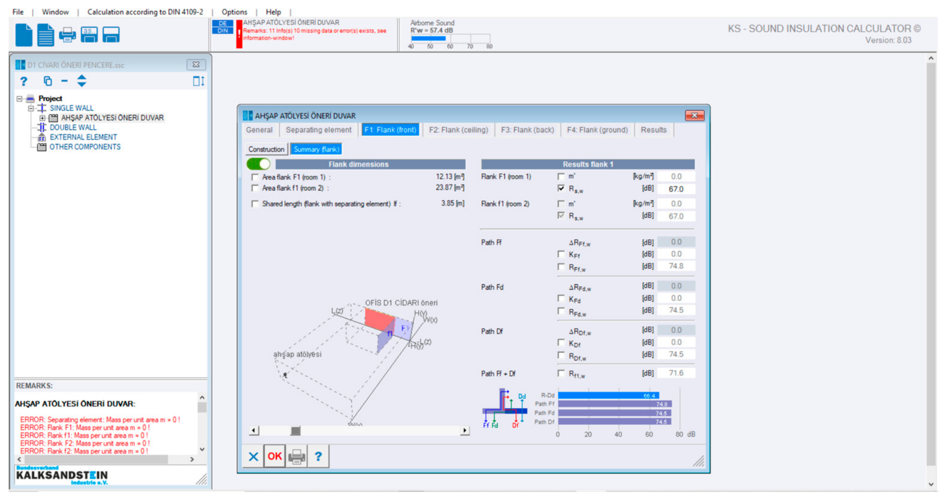
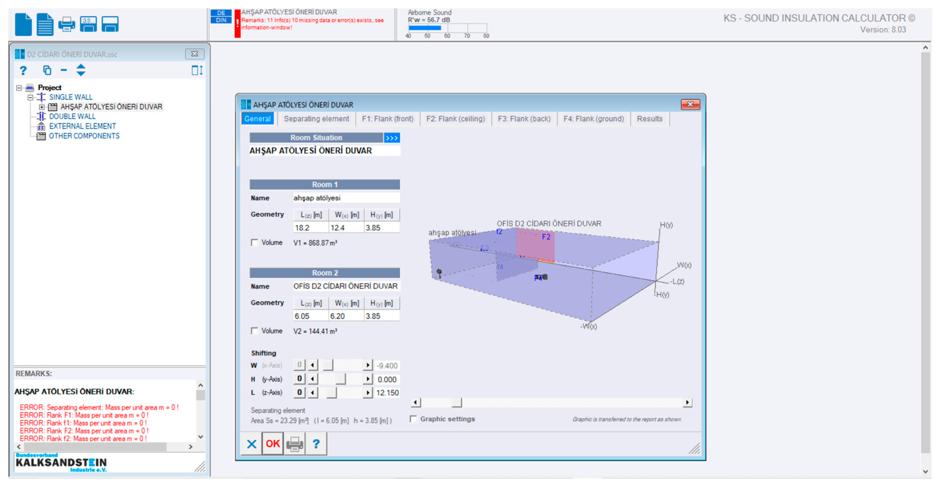
Building ElementDescriptionRw (dB)
CeilingReinforced concrete slab with ceiling/floor finishing layers57
FloorReinforced concrete floor slab with finishing layers55
Wall Y1Single AAC/masonry wall system43
Wall Y3Single AAC/masonry wall system43
Wall Y4Single AAC/masonry wall system43
Wall Y2Double AAC wall with 50 mm air cavity/expansion joint70
Partition D1Aluminum-framed glazed partition system33
Partition D2Aluminum-framed glazed partition system33
Table 5. KS calculated building-scale airborne sound insulation performance of the existing D1 and D2 partition systems.
Building ElementR’w (dB)DnT,w (dB)DnT,A (dB)
D1 (Existing)31.834.833.2
D2 (Existing)32.335.333.7
Table 6. Proposed partition alternatives developed in. Y1–Y3–Y4.
Existing Configuration (Outside to Inside)Thickness (mm)Density (kg/m3)Proposed ConfigurationThickness (mm)Density (kg/m3)
WallGypsum plaster10710Gypsum plasterboard (2 layers)10 × 2 = 20710
Cement plaster251600Rock wool50100
Aerated concrete150600Gypsum plaster10710
Cement plaster251600Cement plaster251600
Gypsum plaster10710Aerated concrete150600
Total Thickness 210 mm Cement plaster251600
Gypsum plaster10710
Rock wool50100
Gypsum plasterboard (2 layers)10 × 2 = 20710
Total Thickness 360 mm
Table 7. Proposed partition alternatives developed in D1.
Existing Configuration (Outside to Inside)Thickness (mm)Density (kg/m3)Proposed Configuration Thickness (mm)Density (kg/m3)
WallGlass 52430Gypsum plasterboard (2 layers)10 × 2 = 20710
Air cavity 6 Rock wool50100
Glass 52430Gypsum plaster10710
Total Thickness 16 mm Cement plaster251600
Aerated concrete150600
Cement plaster251600
Gypsum plaster10710
Rock wool50100
Gypsum plasterboard (2 layers)10 × 2 = 20710
Total Thickness 360 mm
Window Glass52430
Air cavity 6
Glass 52430
Air cavity 339
Glass 52430
Total Thickness 360 mm
Table 8. Proposed design alternatives for the D2 partition system.
Existing Configuration (Outside to Inside)Thickness (mm)Density (kg/m3)Proposed Configuration Thickness (mm)Density (kg/m3)
WallGlass52430Gypsum plasterboard (2 layers)10 × 2 = 20710
Air cavity6 Rock wool50100
Glass52430Gypsum plaster10710
Total Thickness 16 mm Cement plaster251600
Aerated concrete150600
Cement plaster251600
Gypsum plaster10710
Rock wool50100
Gypsum plasterboard (2 layers)10 × 2 = 20710
Total Thickness 360 mm
Door Medium-Density Fiberboard (MDF)10700
Rock wool20100
Medium-Density Fiberboard (MDF)10700
Air cavity285
MDF35700
Total Thickness 360 mm
Table 9. Comparative evaluation of existing and proposed partition systems.
ElementConditionRw (dB)R’w (dB)DnT,w (dB)DnT,A (dB)Change in Predicted DnT,A (dB)Predicted BGKKHY ComplianceVisual Connectivity Preserved Relative Cost
Y1-Y3-Y4Existing43-
Y1-Y3-Y4Proposed67-Low
D1Existing3331.834.833.2-
D1Proposed66.455.958.957.3+24.1Medium
D2Existing3332.335.333.7-
D2Proposed64.255.758.757.1+23.4Medium
Table 10. Noise control approaches and representative design strategies at different control levels.
Control LevelDesign ObjectiveRepresentative Strategies
Source controlReduce noise generationLow-noise machinery, preventive maintenance, machine enclosures, silencers, vibration isolation, optimized production process, low-noise HVAC systems
Transmission path controlReduce airborne sound transmissionFunctional zoning, increased separation distance, buffer spaces, high-performance partitions, optimized glazing ratio, laminated or double glazing, acoustically sealed doors
Receiver controlReduce occupants’ noise exposureOffice zoning, workstation orientation, sound-absorbing finishes, acoustic screens, administrative controls, hearing protection
Disclaimer/Publisher’s Note: The statements, opinions and data contained in all publications are solely those of the individual author(s) and contributor(s) and not of MDPI and/or the editor(s). MDPI and/or the editor(s) disclaim responsibility for any injury to people or property resulting from any ideas, methods, instructions or products referred to in the content.