Article

Design and Vibration Response Analysis of a Novel Lightweight Temporary Steel Platform

1
Hunan Harbor Engineering Co., Ltd., Changsha 410011, China
2
School of Civil Engineering, Central South University, Changsha 410075, China
3
China Construction Third Engineering Bureau (Shenzhen) Co., Ltd., Shenzhen 518110, China
*
Author to whom correspondence should be addressed.
Buildings 2026, 16(17), 3528; https://doi.org/10.3390/buildings16173528
Submission received: 20 July 2026 / Revised: 29 August 2026 / Accepted: 2 September 2026 / Published: 4 September 2026

Abstract

To address the limitations of conventional temporary steel platforms, a novel lightweight temporary steel platform (LTSP) system was developed based on an inland river high-pile wharf project. The proposed system utilizes permanent rock-socketed steel tubular piles of the wharf structure as the primary load-bearing foundation and consists of welded corbels, twin I-beam main girders, secondary I-section distribution beams, and steel deck plates. A construction method integrating permanent and temporary structural components was proposed. Field measurements were conducted to investigate the vibration response characteristics of the LTSP. The results indicate that the platform exhibits relatively high natural frequencies, with all identified fundamental frequencies exceeding 14 Hz, suggesting a low risk of resonance under human-induced excitations. The lateral stiffness of the platform was found to be greater than its vertical stiffness. Pedestrian-induced vibrations were mainly concentrated near excitation locations, whereas vehicle-induced vibrations were more uniformly distributed across the platform. The permanent steel tubular piles provided effective local restraint and enhanced structural stiffness, thereby reducing vibration transmission to adjacent areas. Construction machinery generated the most significant vibration responses, particularly during simultaneous multi-equipment operations. Therefore, to ensure the safety and operational performance of the temporary steel platform, it is recommended to avoid the simultaneous operation of heavy equipment, such as rotary drilling rigs, fully loaded tanker trucks, and truck cranes. Furthermore, as the current findings are based on a single field application case, future studies should incorporate long-term monitoring and numerical modeling to further evaluate the platform’s applicability to other practical engineering projects.

1. Introduction

As a critical application form of steel structures in construction, steel platforms have been widely adopted in the erection of high-rise and super-high-rise buildings, gradually evolving into standardized operational platforms [1,2,3,4]. These platforms offer distinct advantages—including short construction cycles, high component integration, and material reusability—while effectively mitigating the constraints on construction sites often imposed by dense urban development [5,6,7]. In marine and riverine engineering projects—such as port terminals and deep-water bridge piers—temporary steel construction platforms serve as essential support carriers for high-altitude and deep-water operations. They provide stable working and transit conditions for heavy machinery—such as crawler cranes, concrete mixer trucks, and drilling rigs—during the pile foundation and pile cap construction phases [8].
However, existing temporary steel construction platforms primarily consist of modular Bailey bridge-style platforms [9], integrated steel trestle-and-platform systems [10], simple steel pipe pile-supported platforms, and traditional platforms utilizing steel pipe piles combined with structural steel beam systems [11]. The performance characteristics of these temporary platforms are summarized in Table 1. Typically, these platforms rely on independently installed temporary steel pipe piles coupled with highly rigid support systems. While capable of meeting construction requirements, they generally suffer from several drawbacks: excessive structural self-weight, high steel consumption, complex construction and dismantling procedures, high material loss rates, and significant disturbance to the waterbed and surrounding ecological environment during construction. Furthermore, most existing platform systems remain structurally independent of the permanent main structure, failing to achieve the synergistic utilization of structural resources; this increases overall construction costs and procedural complexity. These issues are particularly pronounced within the current global context of “green, low-carbon, and sustainable” development.
Although existing research has explored the structural forms and construction methodologies of various temporary steel platforms, most studies have focused predominantly on structural configuration optimization and construction process improvements. Research regarding the integration of permanent structural components into temporary construction support systems remains relatively limited. Concurrently, investigations into the dynamic response characteristics of lightweight steel platforms under complex construction scenarios, such as the combined effects of vehicular loads and heavy construction equipment, are still insufficient. The lack of systematic experimental data and reliable design guidelines currently restricts the widespread application of such platforms in engineering practice [12,13,14,15].
In light of the aforementioned challenges, and drawing upon the Songyang Lake Phase III Project at the Chenglingji Port Area of Yueyang Port, Hunan Province, this paper proposes a temporary construction technology system that achieves a deep integration between permanent pile foundations and lightweight steel structures. This method utilizes pre-installed permanent piles as vertical load-bearing components to construct a Lightweight Temporary Steel Platform (LTSP). Building upon this foundation, field tests were conducted to assess the platform’s vibration response under various operational scenarios. A systematic analysis of its dynamic characteristics during vehicle transit and construction operations was performed.
The main contributions of this paper are as follows:
(1)
A construction method for lightweight steel platforms based on the collaborative utilization of permanent and temporary structures was proposed, which effectively reduced the amount of temporary works and improved resource utilization efficiency;
(2)
Through field dynamic testing, the vibration response characteristics of the lightweight steel platform under various working conditions were systematically investigated, providing an experimental basis for evaluating the dynamic performance of similar structures;
(3)
Based on the experimental results, corresponding construction control recommendations were proposed to provide a reference for engineering practice.

2. Design and Construction Techniques for Lightweight Temporary Steel Platform

2.1. Design of Temporary Steel Platform

Addressing the limitations of existing temporary steel platforms—particularly low material utilization efficiency, complex construction procedures, and difficulties in pile driving within deep-water areas—and considering the structural characteristics and integrated construction process of high-pile inland river wharves, this study proposed a novel lightweight temporary construction steel platform system. Based on the Songyang Lake Phase III Project at the Chenglingji Port Area of Yueyang Port, Hunan Province, the system utilized the permanent rock-socketed steel pipe piles installed for the main wharf structure as the load-bearing foundation.
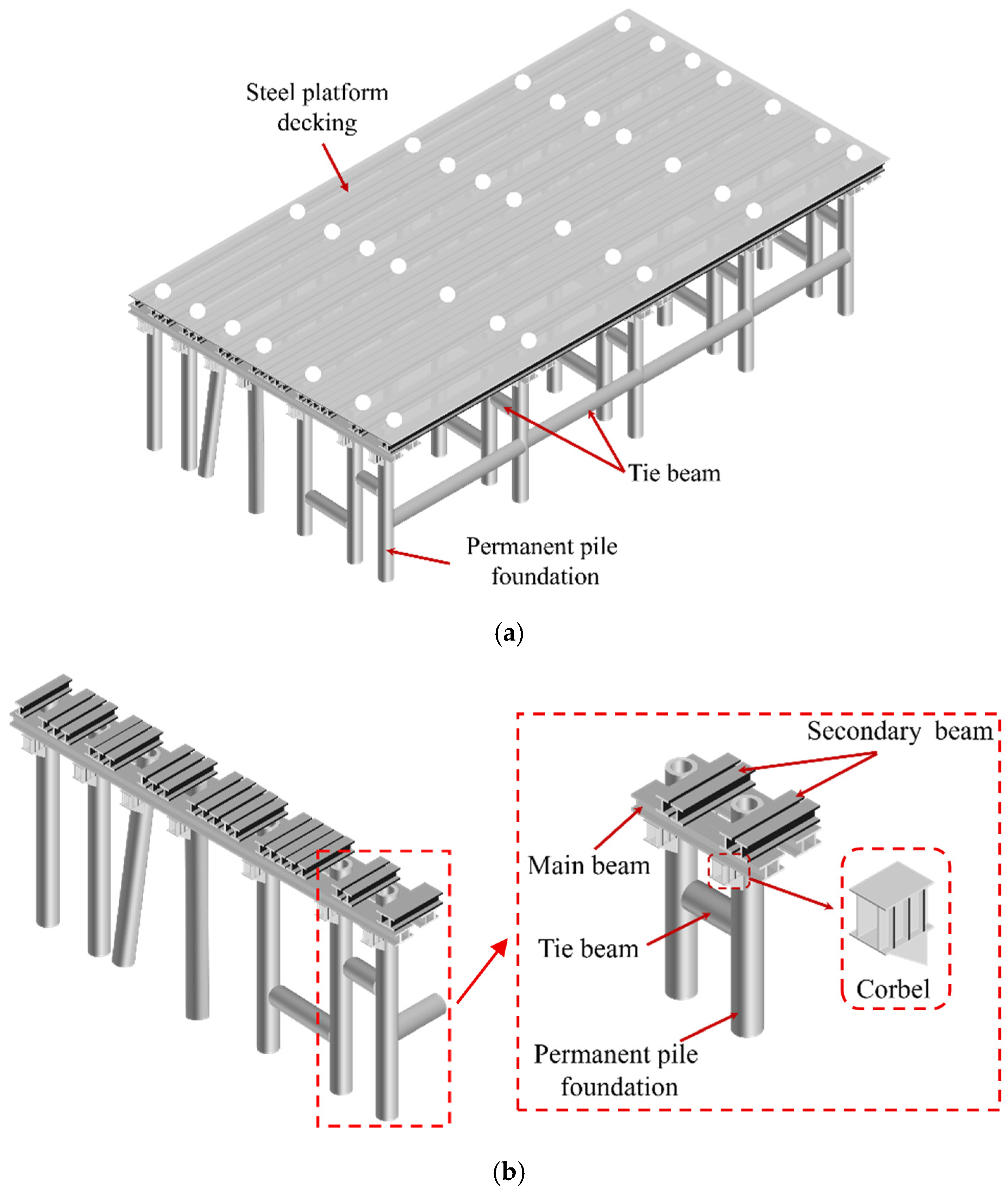
A composite load-transfer system consisting of steel pipe piles, high-strength welded corbels, twin I-beam main girders, I-beam distribution girders, and checkered steel plate decking was established and collectively defined as the Lightweight temporary steel platform (LTSP). The platform had an overall length of 758 m and a width of 25 m.
The vertical load-transfer path of the platform was as follows: dynamic and static loads generated by construction equipment and materials were transmitted through the checkered steel plate decking to the I32a distribution girders, then transferred by the 2I45a main girders to the welded corbels, subsequently delivered to the permanent steel pipe piles, and finally carried by the rock-socketed bearing stratum, as illustrated in Figure 1. The spacing of the I32a distribution girders did not exceed 250 mm, and all structural components of the platform were fabricated from Q235B steel. Detailed information on the material quantities and mechanical properties of the temporary steel platform components is provided in Table 2.
The design of the lightweight steel platform eliminated the need for conventional Bailey bridge systems, thereby reducing the self-weight of the supporting structure. The welded corbels functioned not only as the primary load-bearing components of the platform but also as support bases for the subsequently cast-in-place crossbeams, which simplified both the construction and dismantling processes. Furthermore, by optimizing the arrangement of the main girders and distribution girders and incorporating the recycling of steel materials, the platform achieved a balanced combination of structural performance and economic efficiency.

2.2. Construction Procedure for Temporary Steel Platform

The construction procedure for the lightweight temporary steel platform was as follows:
(1)
Site acceptance inspections were conducted for structural steel sections, steel plates, welding equipment, and hoisting equipment to ensure the smooth implementation of subsequent construction activities.
(2)
Lateral bracing was welded between the permanent steel pipe piles to improve the overall stiffness and stability of the platform.
(3)
The support corbels were positioned and welded.
(4)
I45a steel I-beam main girders were installed on top of the corbels.
(5)
I32a steel I-beam distribution girders were installed above the main girders.
(6)
An 8 mm-thick checkered steel plate decking was laid above the distribution girders.
(7)
Safety protection systems, including platform guardrails and warning signage, were installed.
(8)
Structural force and deformation monitoring was carried out throughout the construction stage of the steel platform.
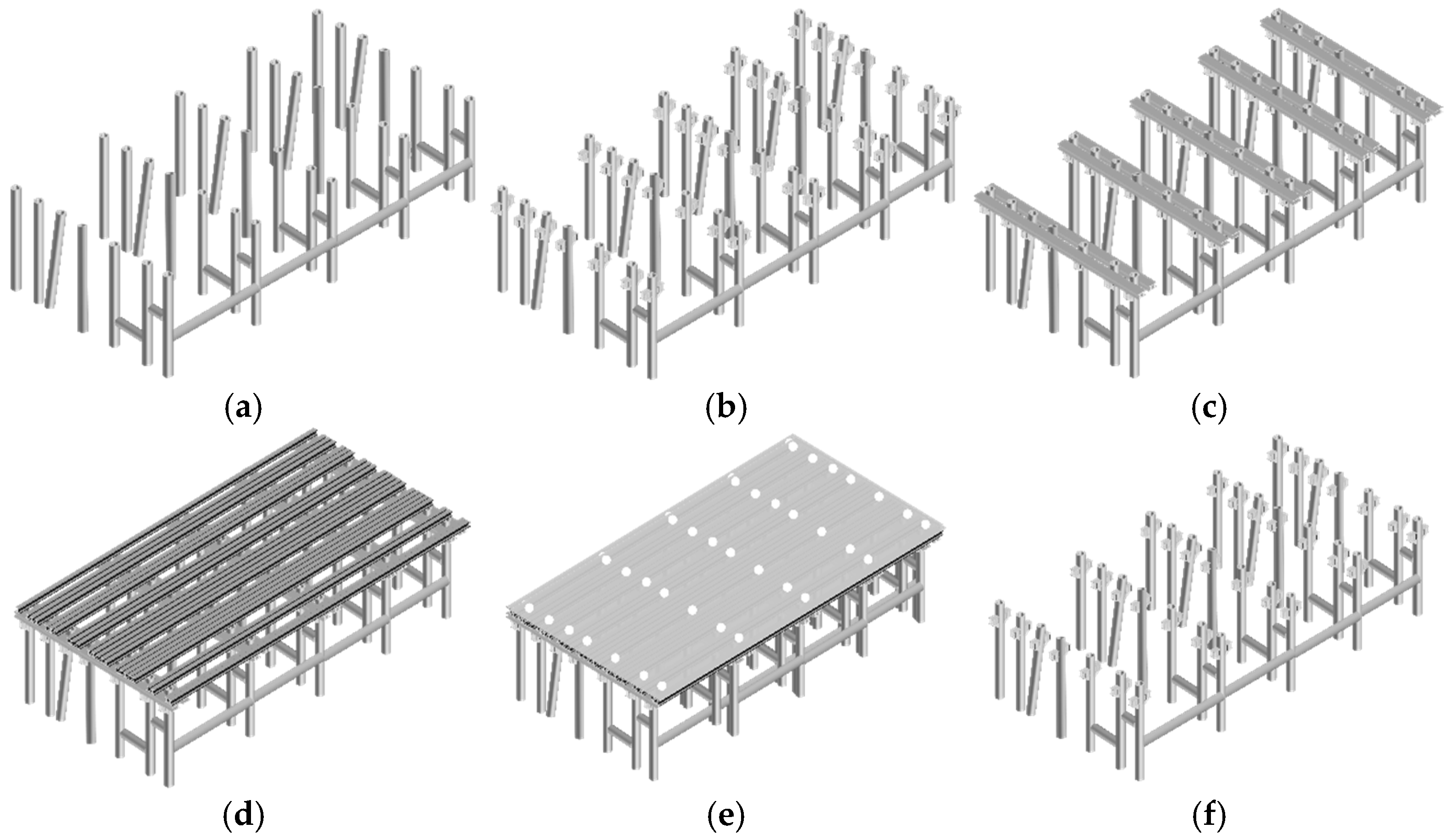
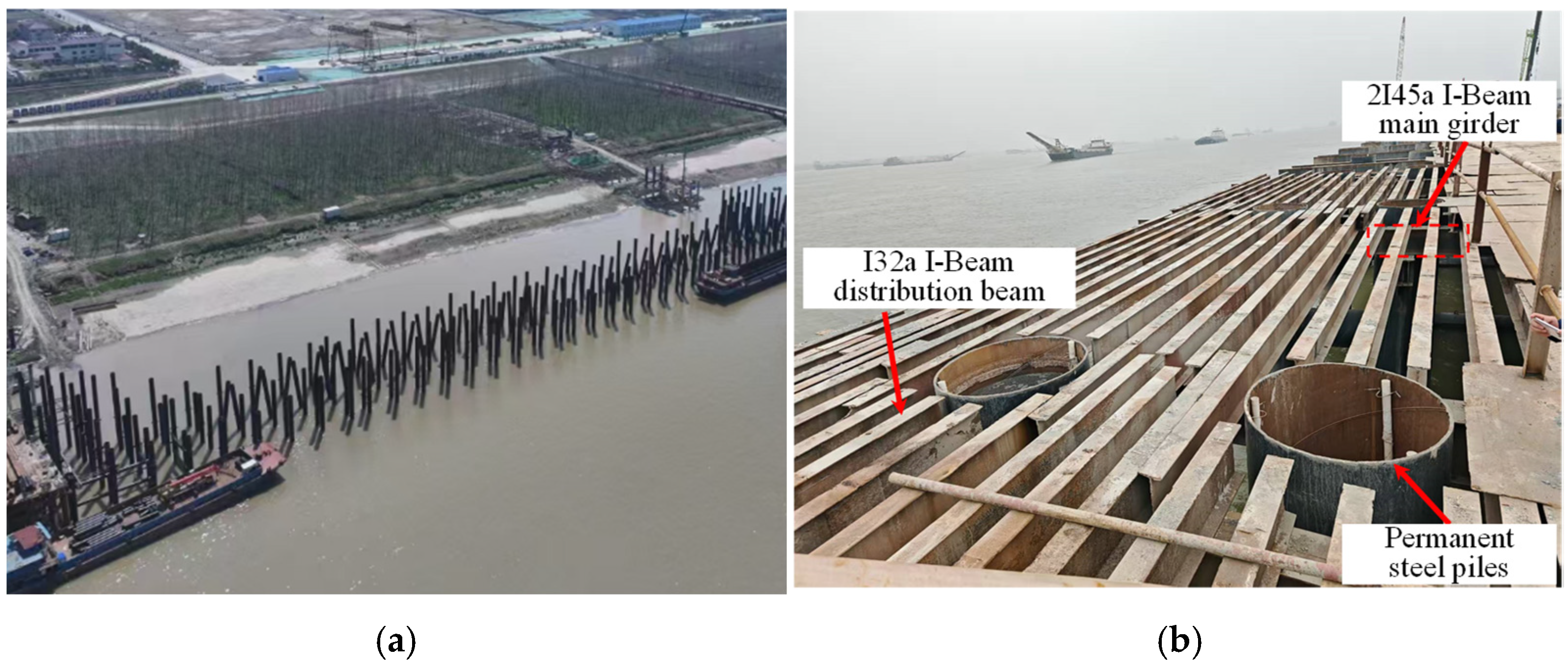
After completion of the steel platform, construction of the pile foundations and superstructure commenced immediately. Upon completion of the project, the steel plate decking, main girders, and distribution girders were dismantled and transported to subsequent construction sites for reuse, thereby improving the recyclability and utilization efficiency of steel materials. In contrast, the welded corbels were retained as support components for the subsequently cast-in-place crossbeams, which avoided the repetitive welding and dismantling procedures commonly associated with conventional temporary steel platforms. The core construction workflow is illustrated in Figure 2, while the actual construction site is depicted in Figure 3.
In addition, real-time monitoring of horizontal displacement and settlement was conducted throughout the erection and operation stages of the steel platform to ensure structural safety and stability during construction.

2.3. Calculations of Strength and Deformation Under Load

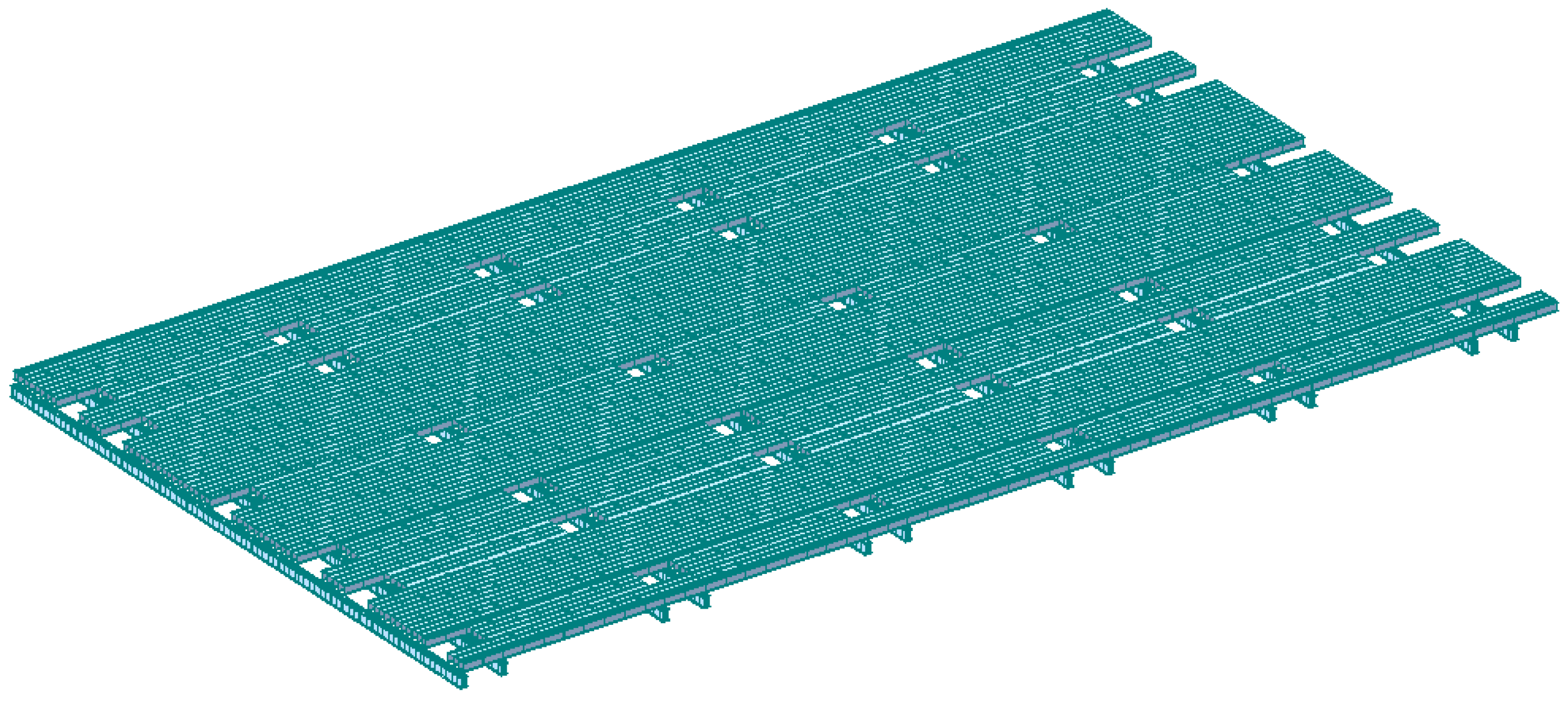
In accordance with the codes of JTS 167-2018 [16] and the JGJ 7-2010 [17], structural stress and deformation checks were performed for the lightweight temporary steel construction platform. The platform primarily supports loads including its self-weight, muck bins, construction personnel and equipment, a 115 T rotary drilling rig, a 10 m3 concrete mixer truck, and an 85 T crawler crane. A spatial finite element model of the lightweight temporary steel platform was established using Midas Civil (2023 v1.1), as shown in Figure 4. The platform’s main beams, secondary beams, distribution beams, and permanent pile foundations were modeled using beam elements, while the steel deck plating was modeled using plate elements. Material behavior was assumed to be linear elastic with small deformations. The steel deck plating and supporting steel beams were connected through shared nodes, assuming deformation compatibility and no relative slip. Connections between the main girders and secondary beams, as well as between the corbels and pile heads, were treated as rigid, without explicitly modeling the local deformations of welds, bolts, or gusset plates. The permanent pile foundations were modeled using beam elements, while the soil was not modeled as a solid continuum; instead, pile–soil interaction was represented using equivalent elastic connections or discrete springs. Necessary displacement constraints were applied to the foundation nodes at the distal ends of the elastic connections to eliminate rigid-body motion of the structure.
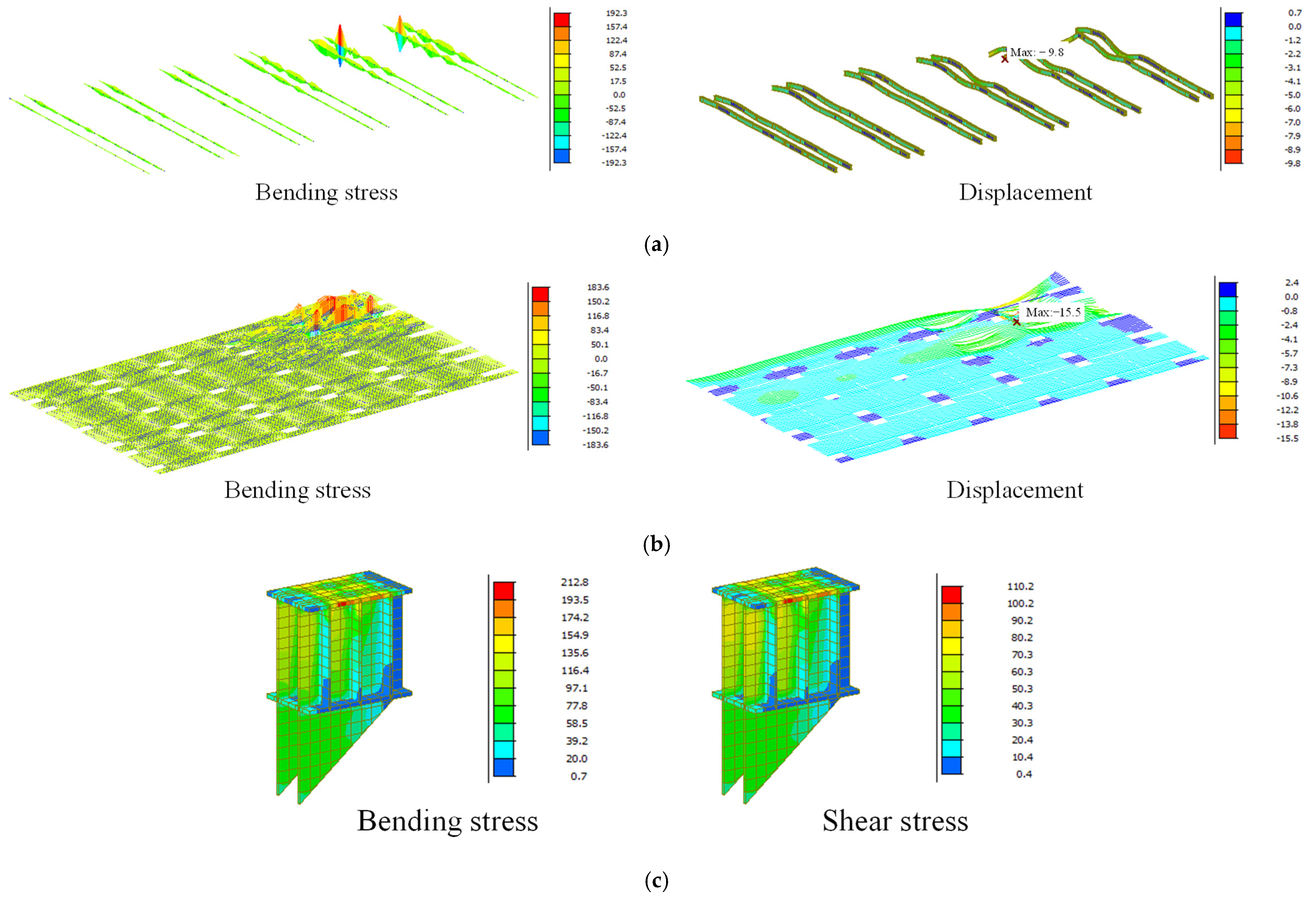
The most unfavorable load cases were selected to verify the stress characteristics of the main platform components, and the calculation results are presented in Table 3 and Figure 5. According to JTS 167-2018 [16], the fundamental combination of actions is applied for structural design at the ultimate limit state, covering both persistent and transient design situations. For structural strength verification, the standard load values are multiplied by the following partial safety factors: 1.2 for permanent loads and 1.4 for variable loads. Conversely, the standard combination of actions is used for component deformation calculations. The partial safety factors for permanent loads and primary variable loads are set to 1.0, while the combination value coefficient for secondary variable loads is set to 0.7.
As shown in Figure 5 and Table 3, it should be noted that “L” in Table 3 represents the spacing between the steel pipe piles (i.e., the single-span length), which is 6400 mm for this temporary steel platform. The strength and deformation characteristics of the primary components, including the checkered steel plates, distribution beams, main girders, corbels, and permanent steel pipe piles, meet the requirements of the design specifications, demonstrating the sound design of the temporary steel platform.

3. Vibration Testing of Lightweight Temporary Steel Platform

The lightweight temporary steel platform was fabricated entirely from steel components. Owing to the relatively low stiffness and high flexibility of the structural system, the platform was particularly sensitive to dynamic excitations induced by pedestrian activities, vehicular traffic, and construction operations. Therefore, it was necessary to investigate the vibration responses of the lightweight temporary steel platform under pedestrian loading, vehicle movement, and construction conditions. To this end, systematic dynamic vibration tests were conducted on the steel platform during vehicular operation and construction activities, while the corresponding vibration response data of the platform were simultaneously collected and analyzed.

3.1. Instrument Layout and Installation

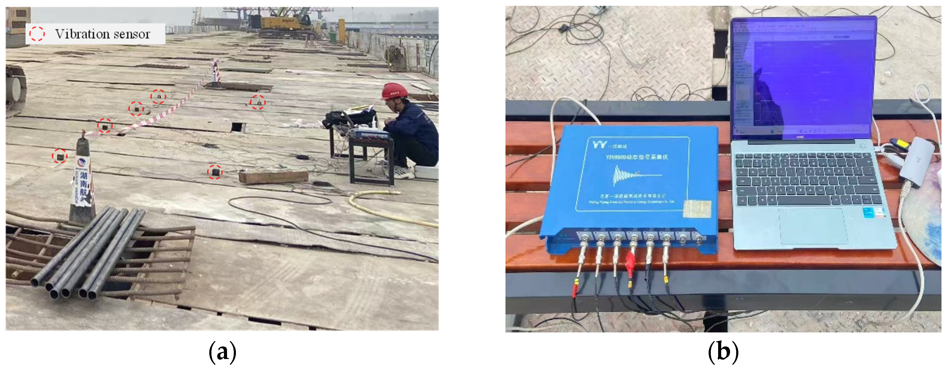
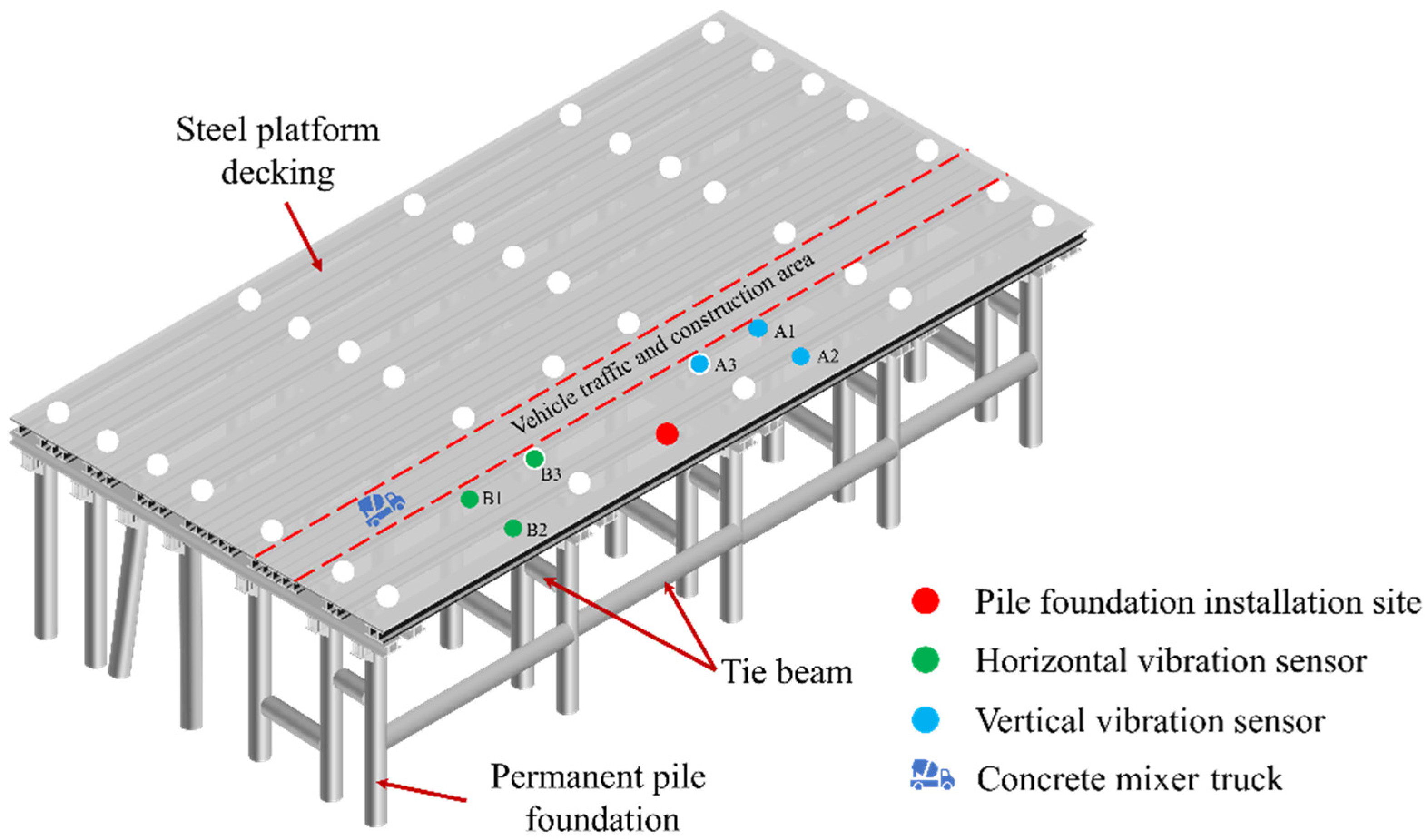
To analyze the dynamic response of the temporary steel platform under natural environmental excitation, as well as during crane operations and construction activities, vibration sensors (accelerometers) were used to record the vibration acceleration of the platform under different operational conditions. Considering the large surface area of the lightweight steel platform proposed in this study, a localized region along the platform edge was selected for dynamic response analysis to capture vibration characteristics under relatively critical conditions. The instrumentation layout and field test setup are shown in Figure 6 and Figure 7, respectively.
To comprehensively characterize the vibration response in different directions, three horizontal sensors (B1, B2, and B3) and three vertical sensors (A1, A2, and A3) were installed to measure horizontal and vertical acceleration responses, respectively. The accelerometers used were all magneto-electric vibration sensors (2D001V, Beijing Yiyang Strain and Vibration Testing Technology Co., Ltd., Beijing, China) with a sensitivity of 0.3 V/m⋅s−2 and a measurement range of ±5 g. Prior to testing, all sensors were calibrated to ensure consistency among the different units. During installation, the sensors were securely connected to the steel platform structure to minimize the influence of relative motion on the test results. The vibration acceleration signals were collected using a YSV dynamic data acquisition system at a sampling frequency of 1020.4 Hz [18,19].

3.2. Test Condition Design

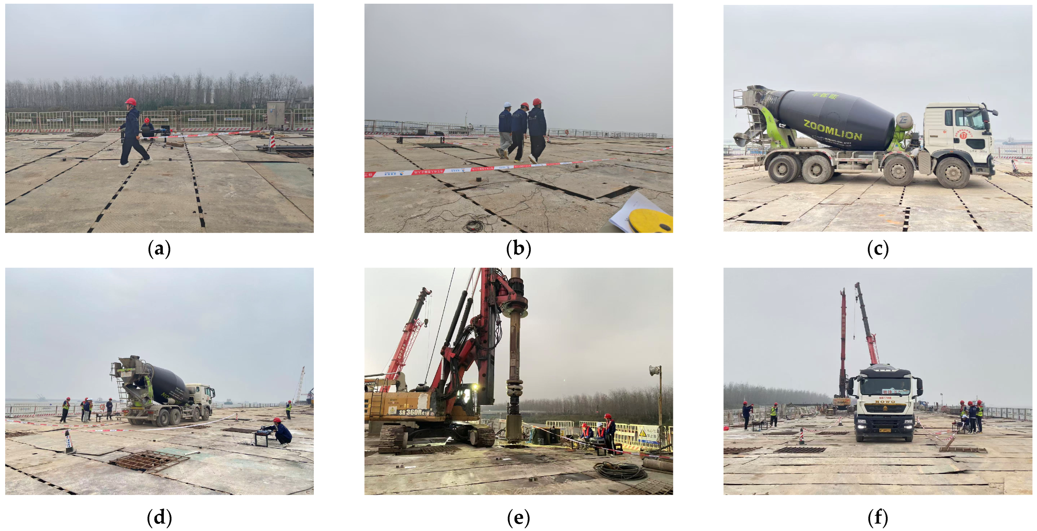
The vibration responses of the temporary steel platform were tested under various excitation sources, including ambient, human-induced, vehicular, and construction-related excitations. Human-induced excitations included walking by one, three, or five individuals (each weighing approximately 70 kg). Vehicular excitations involved the movement of an empty tanker truck and a fully loaded tanker truck. Construction-related excitations consisted of the operation of a rotary drilling rig, as well as the coordinated operation of a rotary drilling rig, a fully loaded tanker truck, and a truck crane. The specific test protocols for vehicular movement and construction activities are presented in Table 4, while the implementation of these tests is illustrated in Figure 8.
In-situ vibration testing was conducted during the construction of the platform. The operating conditions of construction equipment and key environmental conditions were recorded simultaneously during the tests to distinguish the effects of different excitation sources on the platform’s vibration response. It should be noted that the in-situ tests were inevitably affected by factors such as the operating status of construction equipment, ambient noise, and random on-site excitations. Therefore, three tests were conducted for each set of operating conditions, and the final result was taken as the average of the three measurements [20].

4. Discussion and Analysis

Through experimental testing, the fundamental dynamic response parameters of the temporary steel platform were obtained. The response time-history curves reflected the temporal evolution of these dynamic parameters, thereby providing an intuitive representation of the system response characteristics over time. In addition to time-domain analysis, frequency-domain analysis provided another important perspective for characterizing vibration signals. It described the frequency composition of the signals and revealed the amplitude distribution characteristics of different frequency components, thereby facilitating the identification and analysis of excitation components that may adversely affect the temporary steel platform.

4.1. Effect of Ambient Environmental Excitation

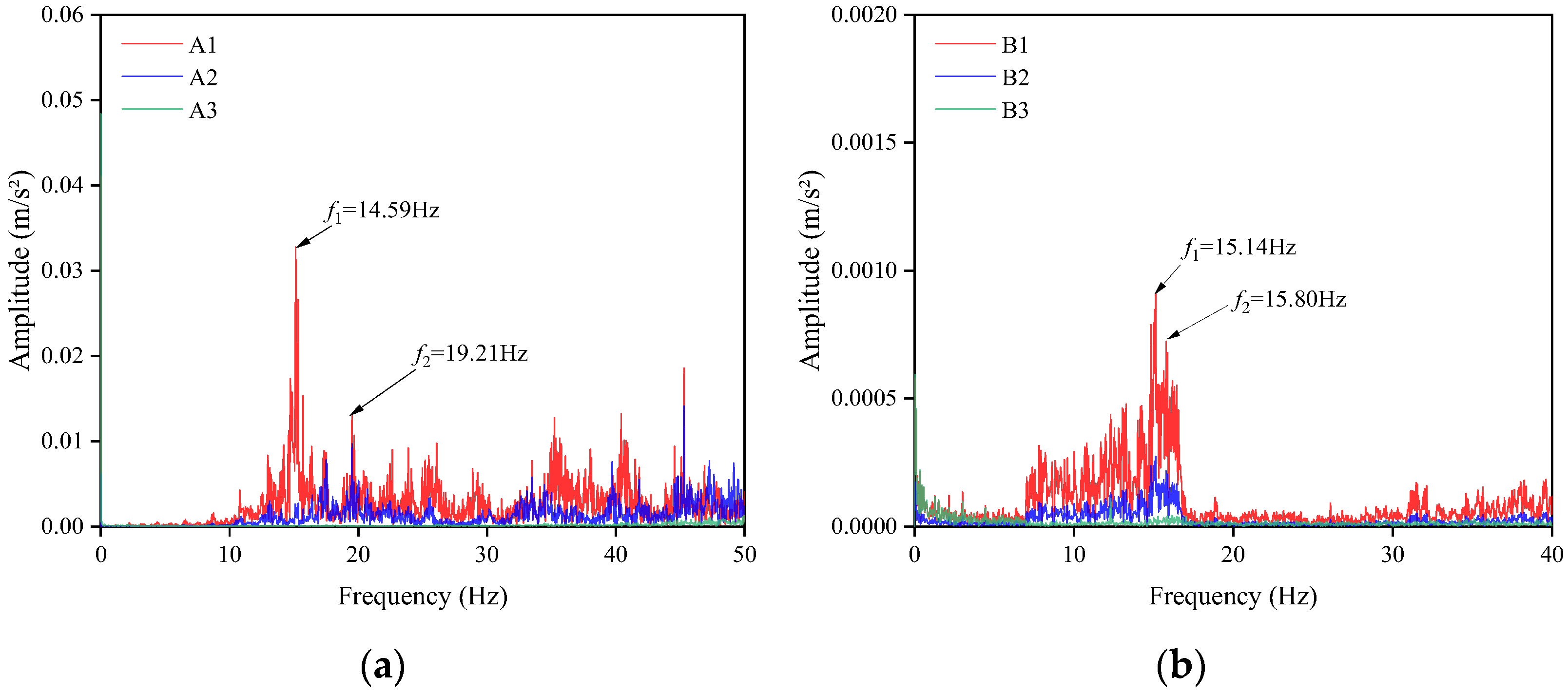
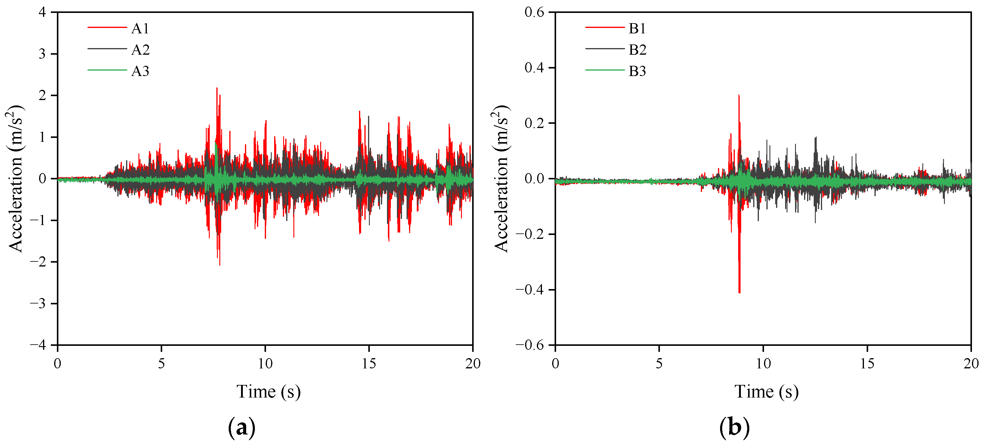
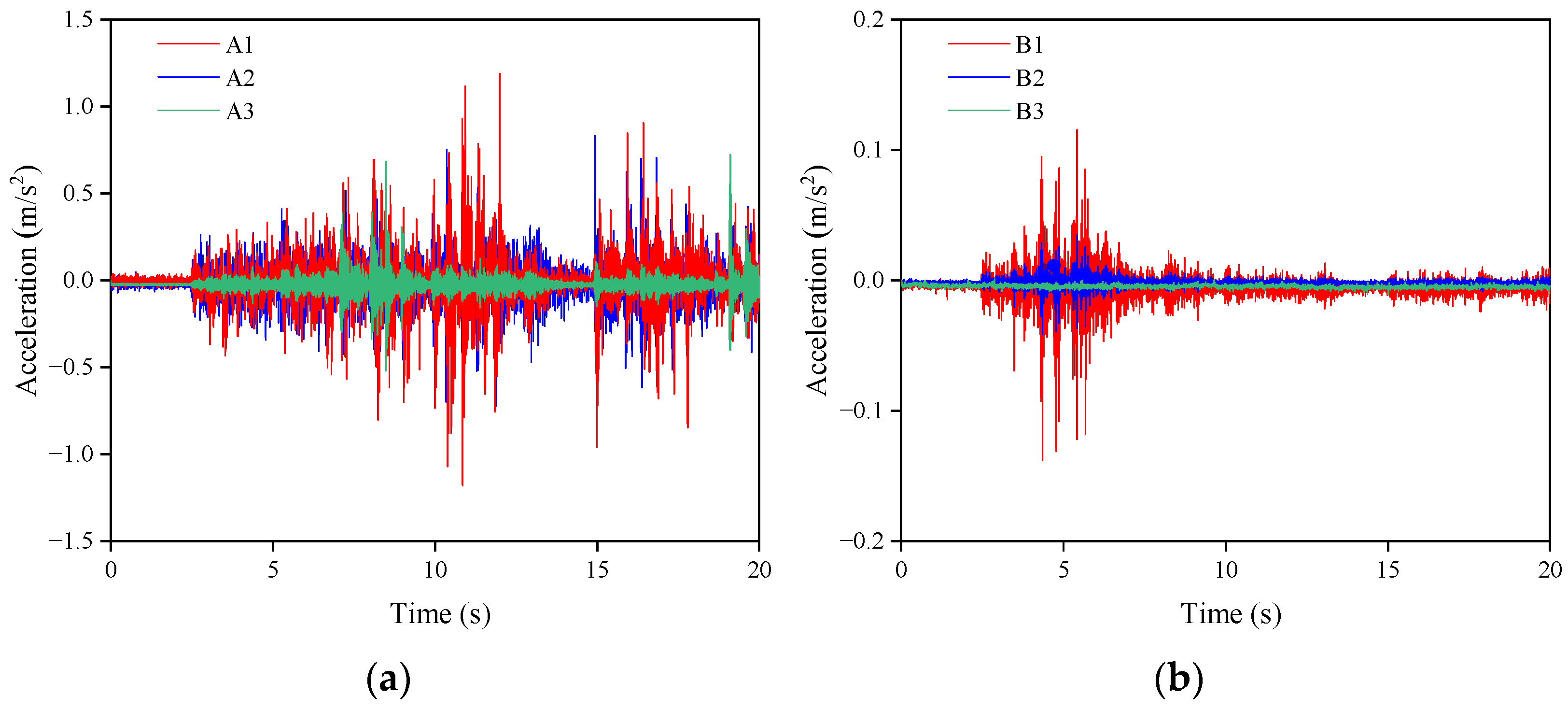
The acceleration responses obtained under ambient environmental excitation were recorded as time-history data. These data were subsequently processed using Fourier transform techniques to obtain acceleration amplitude spectra, in which the peak frequencies corresponded to the natural vibration characteristics of the structure. To reduce the influence of noise, the acceleration spectra were smoothed prior to analysis. Figure 9 and Figure 10 present the acceleration time-history curves and acceleration amplitude-frequency spectra of the temporary steel platform, respectively.
The results indicate that, under ambient environmental excitation, the acceleration responses measured by the vertical and horizontal sensors exhibited generally consistent trends. However, the responses recorded by sensors A3 and B3 were lower than those measured at the other sensor locations. This phenomenon can be attributed to the fact that the steel plates beneath sensors A3 and B3 were directly supported by permanent pile foundations, which provided greater local stiffness and support capacity, thereby resulting in lower acceleration responses.
Furthermore, the spectral characteristics measured by the vertical and horizontal accelerometers at different locations on the temporary steel platform exhibited good consistency. The natural frequencies of the platform were identified based on the dominant peaks in the amplitude spectra. Specifically, the first two vertical natural frequencies were determined to be 14.59 Hz and 19.21 Hz, while the first two lateral natural frequencies were 15.14 Hz and 15.80 Hz, respectively. These results indicate that the temporary steel platform possessed relatively high natural frequencies, with a comparatively sparse distribution of dominant frequencies within the same vibration direction.
In addition, all fundamental natural frequencies of the temporary steel platform exceeded 14 Hz. Since human-induced excitations generally involve low-frequency vibrations in the range of approximately 1~3 Hz, pedestrian activities were unlikely to induce resonance in the structure. Moreover, according to ISO 2631–1:1997 [21], humans are most sensitive to vertical vibrations within the frequency range of 4~12 Hz, which is lower than the fundamental frequencies of the temporary steel platform. Therefore, from the perspective of structural natural frequencies, the temporary steel platform was unlikely to cause significant vibration discomfort.

4.2. Pedestrian-Induced Vibration

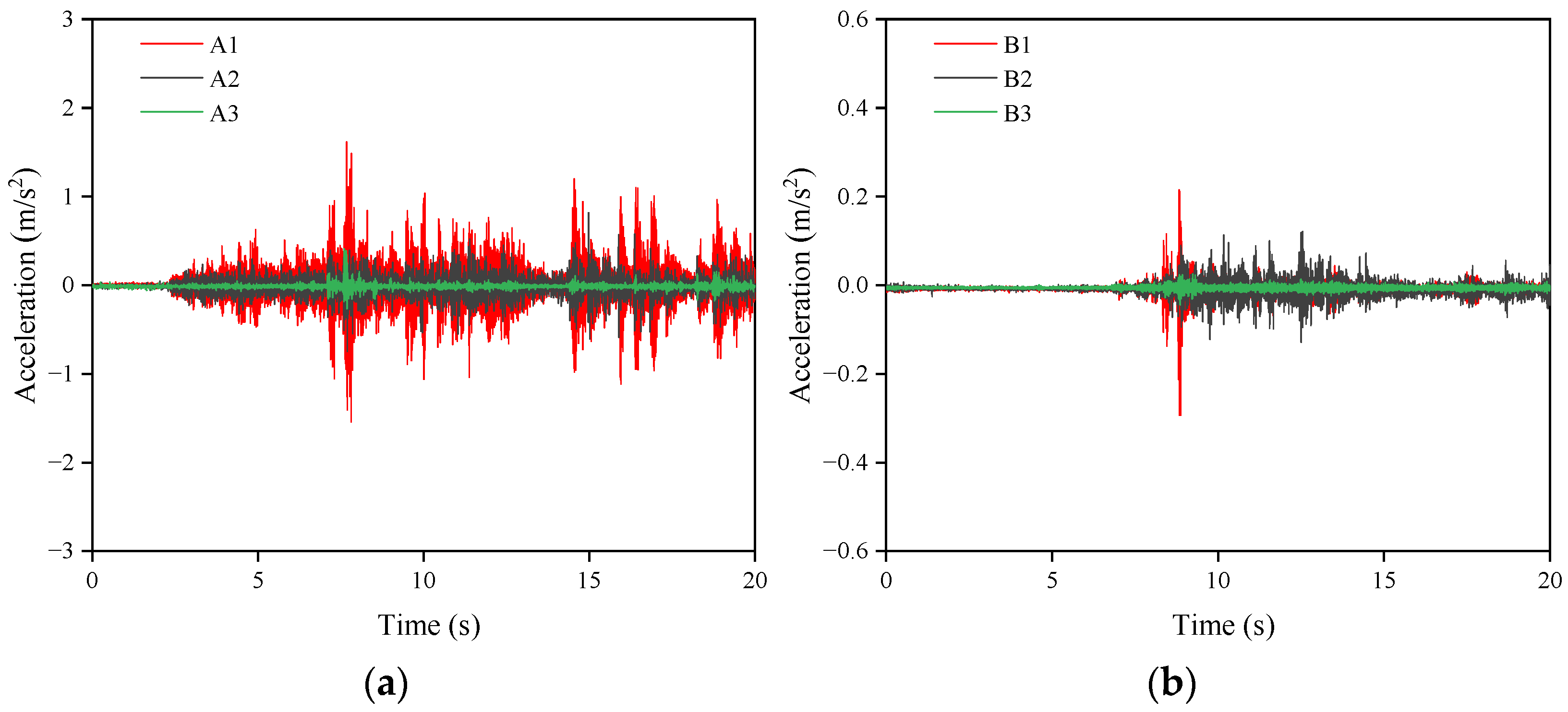
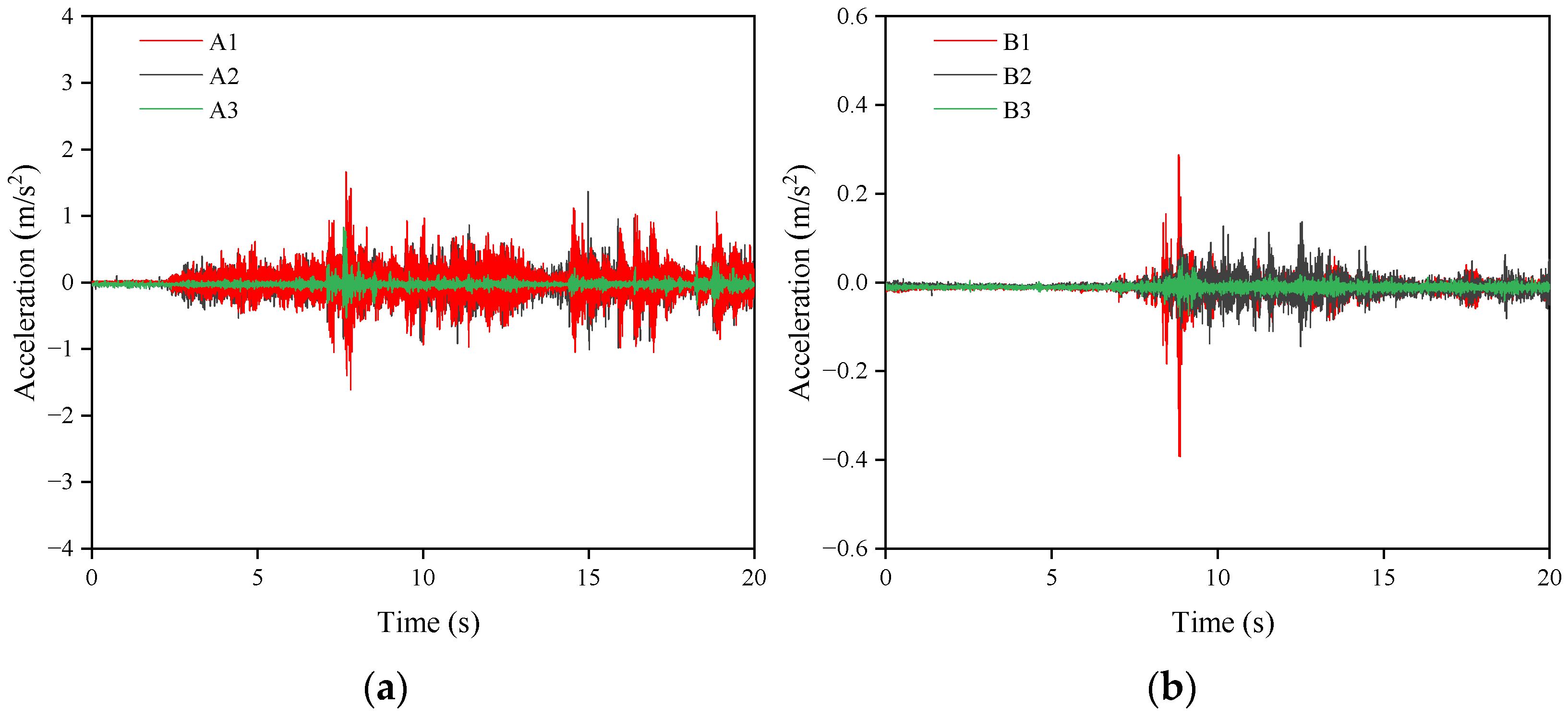
Figure 11, Figure 12 and Figure 13 present the horizontal and vertical acceleration time-history curves of the temporary steel platform under walking excitations involving different numbers of pedestrians. The results indicate that pedestrian walking excitations exerted a relatively limited influence on the overall vibration response of the temporary steel platform. Under single-person, three-person, and five-person walking conditions, the peak vertical accelerations were 1.61 m/s2, 1.63 m/s2, and 2.18 m/s2, respectively, while the corresponding peak horizontal accelerations were 0.29 m/s2, 0.40 m/s2, and 0.41 m/s2, respectively.
Among the three vertical sensors, measurement point A1 exhibited the largest acceleration response, followed by A2, whereas A3 recorded the smallest response. A similar trend was observed for the horizontal sensors, with B1 showing the largest response, followed by B2 and then B3. This phenomenon can be mainly attributed to the fact that sensors A1 and B1 were located closer to the pedestrian excitation region, whereas A3 and B3 were positioned near the permanent pile foundations. Due to the restraining and stiffening effects provided by the pile foundations, the vibration responses at these locations were relatively reduced.
Pedestrian walking excitations generated periodic fluctuations in acceleration responses, and the vibration magnitude was jointly influenced by factors such as walking posture, gait characteristics, step frequency, the relative distance between the excitation source and the sensors, and the local flexural stiffness of the steel platform. In practical engineering vibration assessments, acceleration signals generally exhibit substantial randomness and variability [18,20]. Therefore, the international organization for standardization (ISO) recommends the use of root mean square (RMS) acceleration as the primary evaluation index for vibration responses induced by human activities and vehicular loading. The corresponding calculation formula is given in Equation (1). According to ISO 2631-1:1997 [21] evaluation standards, a time window of 1.0 s was adopted for the RMS calculations.
a R M S = 1 T 0 T a 2 t d t
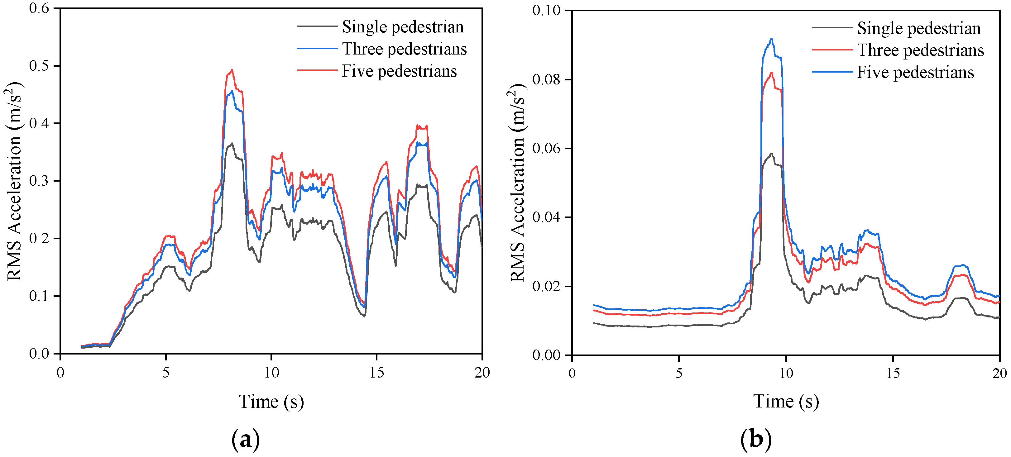
where a ( t ) represents the acceleration response as a function of time, and T denotes the duration of the test. The root mean square (RMS) acceleration provides an integrated measure of the vibration intensity over the entire test period. Based on the analysis results shown in Figure 11, Figure 12 and Figure 13, measurement points A1 and B1 exhibited the maximum vertical and horizontal acceleration responses, respectively. Therefore, the RMS accelerations corresponding to these two measurement points were selected for further analysis, and the results are presented in Figure 14 and Table 5.
As shown in Figure 14 and Table 5, pedestrian-induced excitation primarily generated localized vibrations in the temporary steel platform. Moreover, as the number of pedestrians increased, the vibration response of the platform became progressively more pronounced. When pedestrians moved closer to the sensor locations, the acceleration response within the excited region increased significantly. In addition, under all pedestrian excitation conditions, the measured vertical acceleration consistently exceeded the horizontal acceleration, indicating that the horizontal stiffness of the temporary steel platform was greater than its vertical stiffness. Although pedestrian loading generated noticeable local vibration responses, the vibration influence remained localized around the excitation region. This behavior is consistent with the characteristics of lightweight steel structures reported in previous experimental investigations, where local stiffness and support conditions significantly affect vibration propagation [22,23].
Furthermore, according to the weighted RMS acceleration ranges specified in ISO 2631-1:1997 [21] for evaluating human whole-body vibration comfort, no discomfort is experienced at levels below 0.315 m/s2, whereas slight discomfort occurs within the range of 0.315~0.63 m/s2. As shown in Figure 14, the RMS vertical acceleration induced by human activities is less than 0.63 m/s2, while the RMS horizontal acceleration is less than 0.315 m/s2. Therefore, under pedestrian-induced excitation conditions on the temporary steel platform, the measured responses fell within the corresponding comfort ranges specified by ISO 2631-1:1997.

4.3. Driving-Induced Vibration

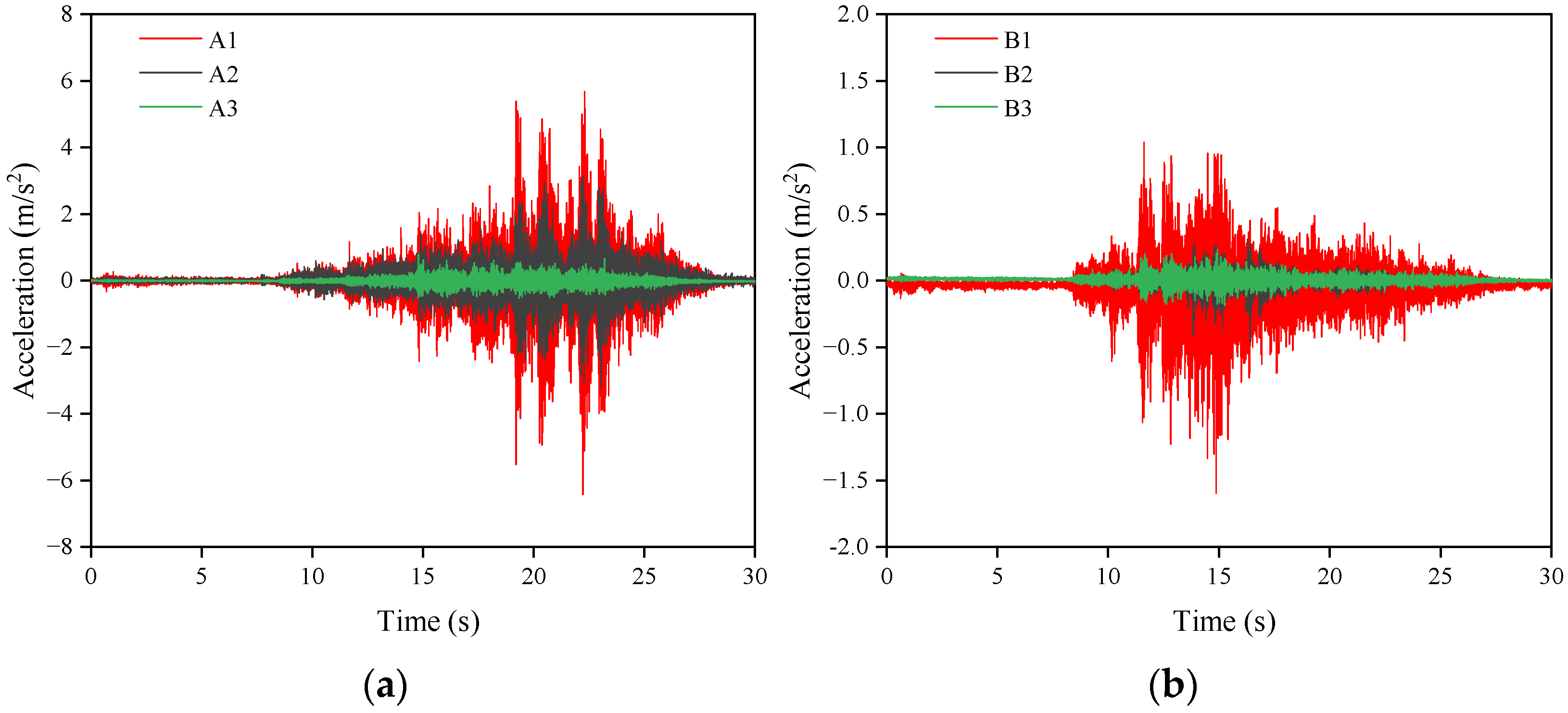
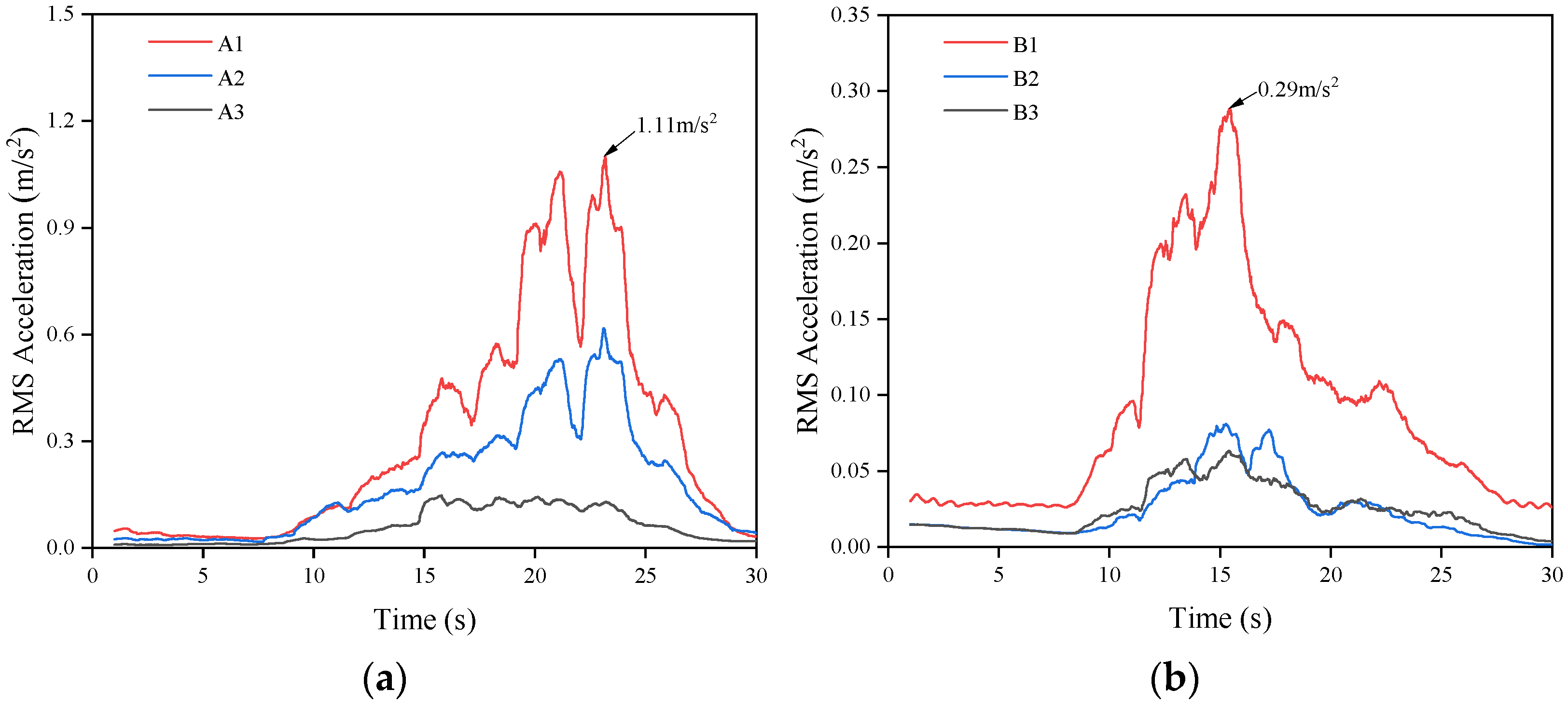
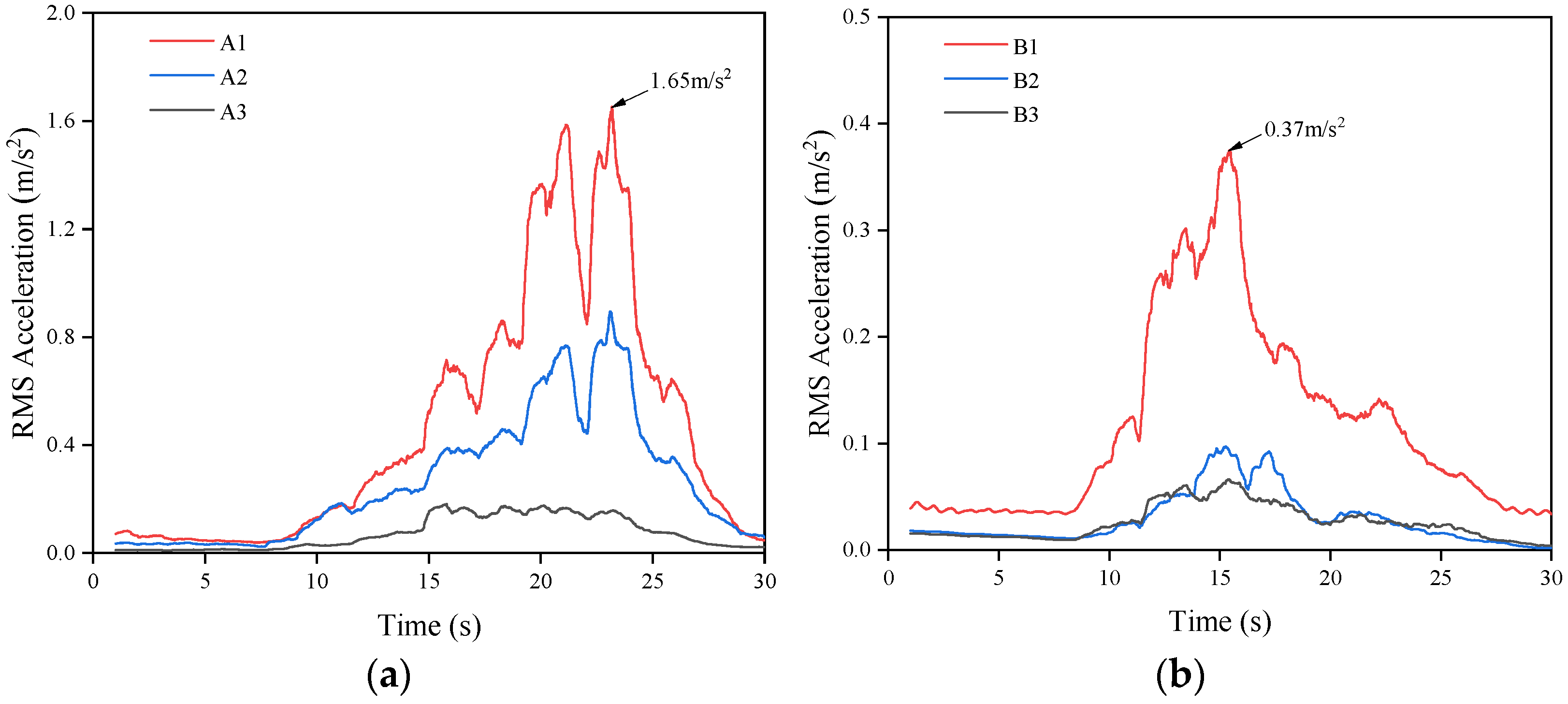
Figure 15 and Figure 16 present the horizontal and vertical acceleration time-history curves of the temporary steel platform under vehicle-induced excitation in both unloaded and loaded conditions, while Figure 17 and Figure 18 and Table 5 show the corresponding root mean square (RMS) acceleration time-history curves. The results indicate that, compared with pedestrian-induced excitation, vehicle-induced excitation generated significantly greater vibration responses in the temporary steel platform. Under the unloaded and loaded vehicle conditions, the peak vertical accelerations reached 4.28 m/s2 and 6.42 m/s2, respectively, whereas the corresponding peak horizontal accelerations were 0.94 m/s2 and 1.60 m/s2.
Furthermore, as illustrated in Figure 17 and Figure 18 and Table 5, measurement points A1 and B1 exhibited the largest RMS acceleration responses under vehicle excitation. Under the unloaded condition, the peak vertical and horizontal RMS accelerations were 1.11 m/s2 and 0.29 m/s2, respectively, while under the loaded condition, these values increased to 1.65 m/s2 and 0.37 m/s2.
In addition, both the acceleration time-history curves and the RMS acceleration curves exhibited a high degree of consistency in describing the overall vibration response of the steel platform under vehicle excitation. Measurement points A1 and A2, as well as B1 and B2, displayed similar waveform characteristics, indicating that the vibration response distribution of the temporary steel platform was relatively uniform under vehicular loading. In contrast, the peak accelerations recorded at measurement points A3 and B3 were comparatively smaller. This phenomenon suggests that the permanent steel pipe pile foundations provided stronger local support and restraint in these regions, thereby enhancing the local stiffness of the platform and effectively reducing the vibration response induced by vehicle loads.

4.4. Construction-Induced Vibration

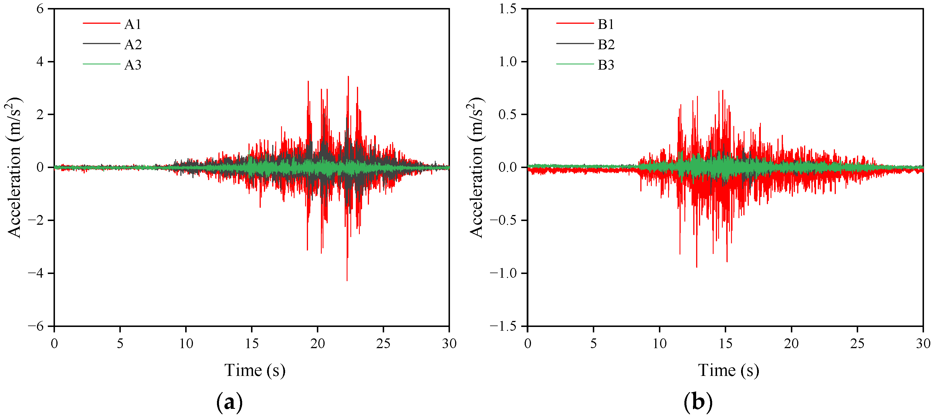
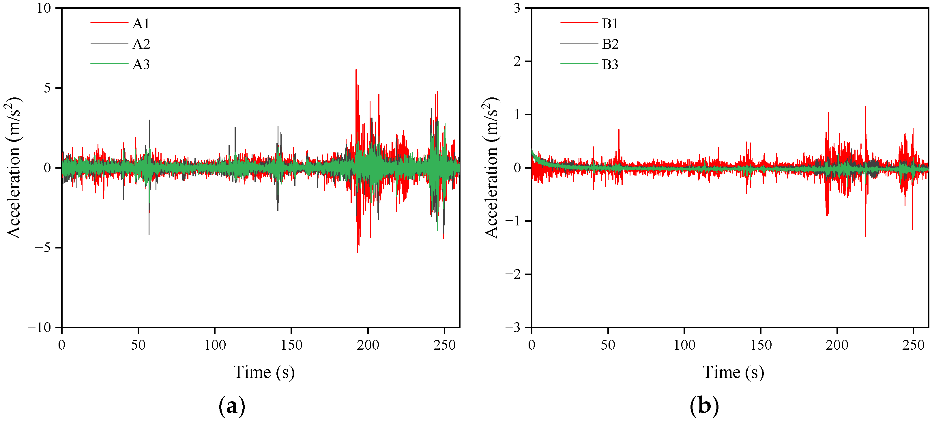
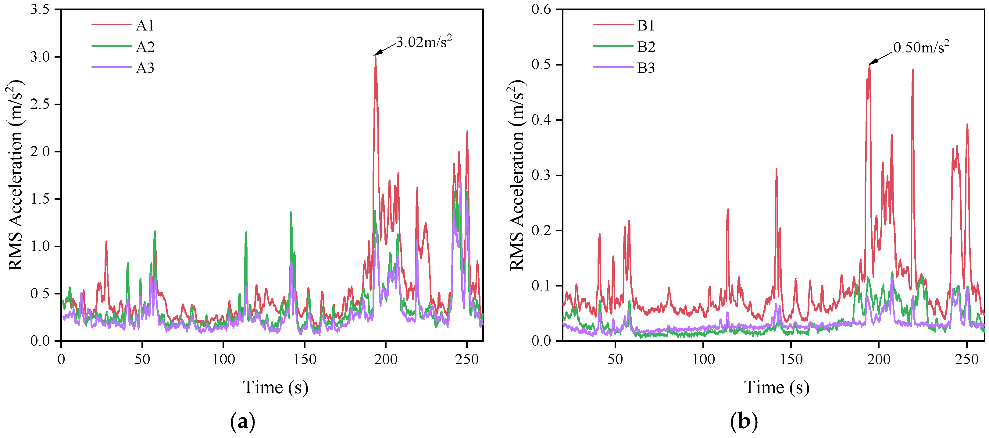
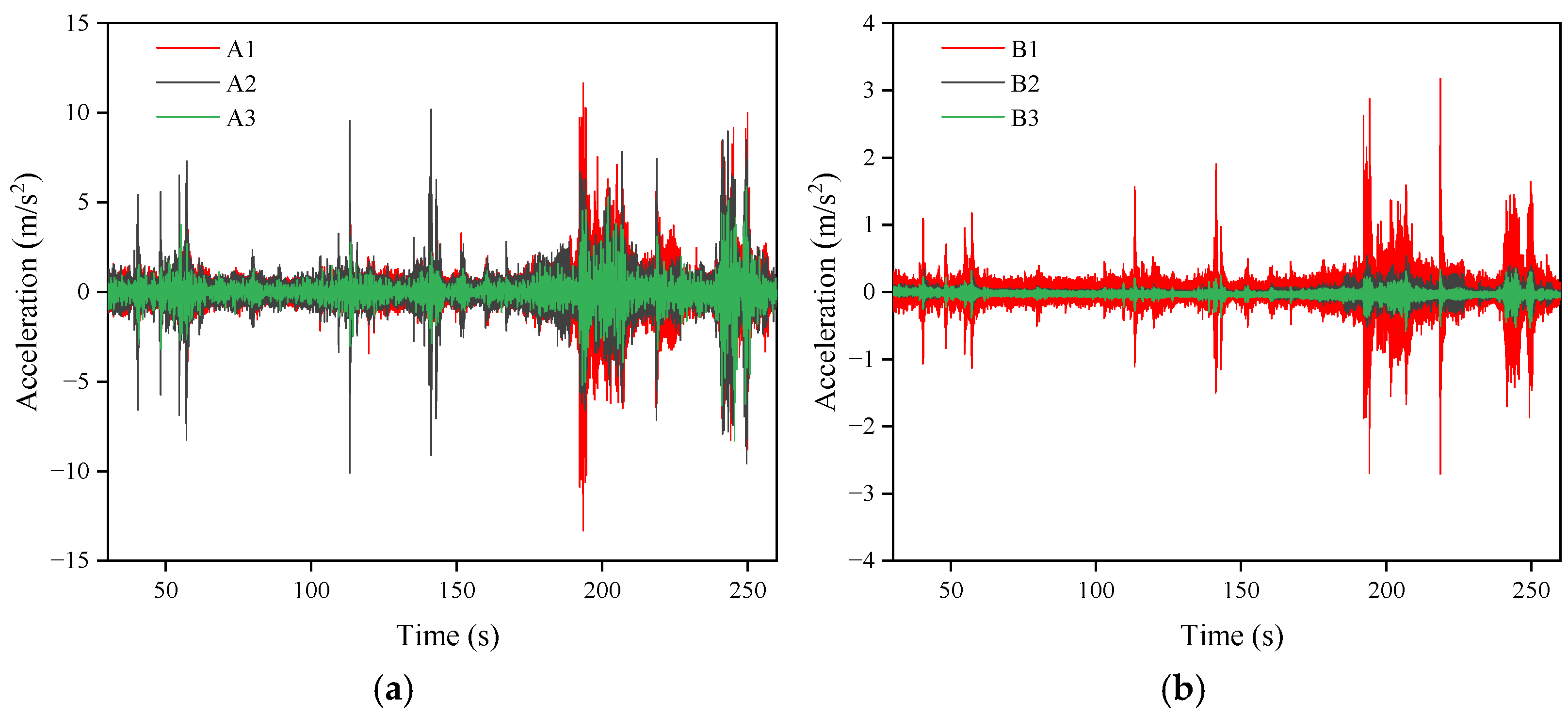
In addition to supporting the movement of construction personnel and vehicles, the temporary steel platform was also required to accommodate large rotary drilling rigs for pile foundation construction. Consequently, particular attention was paid to the vibration responses induced by construction activities. The vibration responses of the temporary steel platform were therefore monitored under two working conditions: rotary drilling operations alone and combined construction operations, as shown in Figure 19 and Figure 20.
The results indicate that combined construction operations generated significant vibration responses in the temporary steel platform, with peak vertical and horizontal accelerations reaching 11.65 m/s2 and 3.17 m/s2, respectively. Moreover, under both independent rotary drilling operations and combined construction operations, the vertical acceleration responses recorded at the three measurement points remained relatively consistent. This phenomenon indicates that the vibration response induced by construction activities was distributed relatively uniformly throughout the temporary steel platform, while the localized restraining effect provided by the permanent pile foundations became less pronounced.
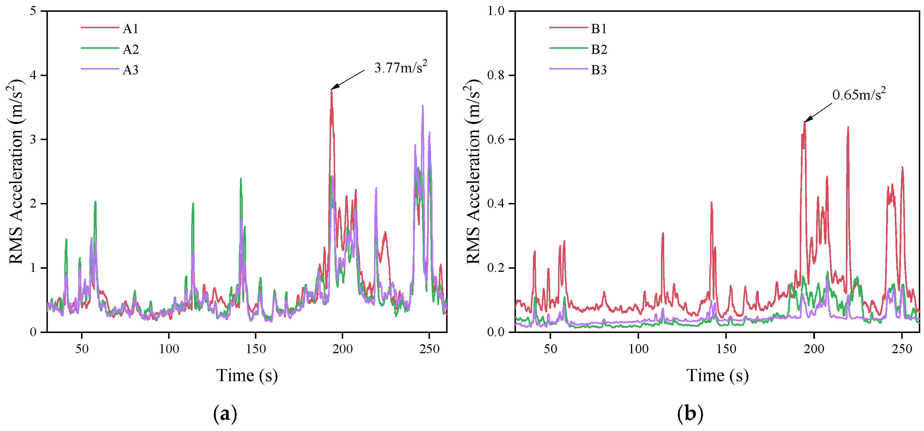
Figure 21 and Figure 22 and Table 5 further present the time-history curves of the root mean square (RMS) accelerations. Under rotary drilling operations alone, the peak vertical and horizontal RMS accelerations were 3.02 m/s2 and 0.50 m/s2, respectively, whereas under combined construction operations, these values increased to 3.77 m/s2 and 0.65 m/s2. The above results demonstrate that the vibration response of the temporary steel platform was significantly amplified during combined construction activities. Therefore, to ensure the safety and stability of the temporary steel platform during construction, simultaneous operation of multiple heavy construction activities should be avoided whenever possible.

4.5. Frequency-Domain Analysis

To determine the frequency-domain response characteristics of the temporary steel platform under various excitations, a Fast Fourier Transform (FFT) was performed on the measured acceleration time-history data. First, linear detrending was applied to the raw acceleration signals to eliminate low-frequency drift and baseline offsets. Subsequently, a Hann window was applied to the signals to mitigate spectral leakage caused by the truncation of finite-duration data. For acceleration time-history records containing N = 25,600 sampling points, the number of FFT points used for spectral calculation was set equal to the length of the raw data, with no zero-padding or preset band-pass filtering applied. The sampling frequency was fs = 1020.4 Hz, corresponding to a Nyquist frequency of 510.2 Hz and a frequency resolution of Δf = fs/N = 0.03986 Hz. Following the FFT computation, only the single-sided amplitude spectrum within the 0~510.2 Hz range was retained, and amplitude correction was performed using the coherent gain of the Hann window to obtain the single-sided acceleration amplitude spectrum in units of m/s2. The primary frequency response characteristics of the platform under different excitations were identified by comparing the spectral peaks and their corresponding frequencies across various measurement points.
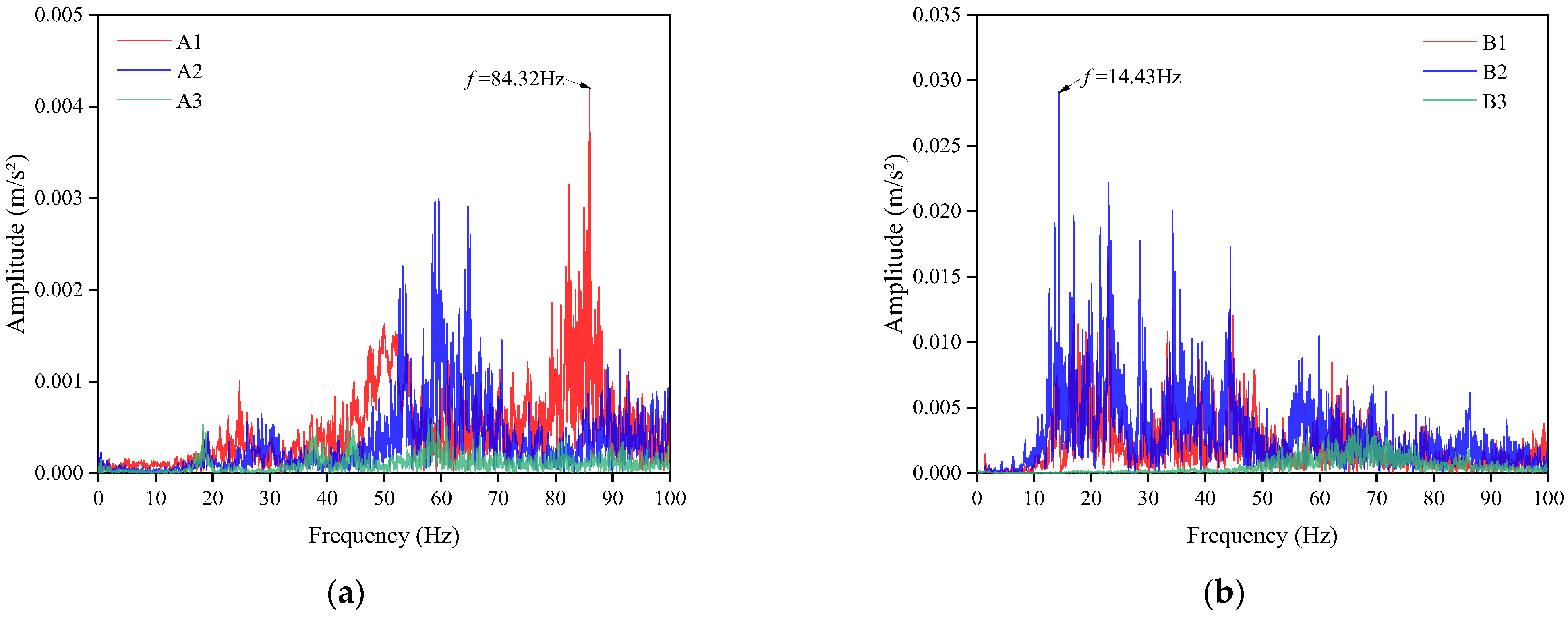
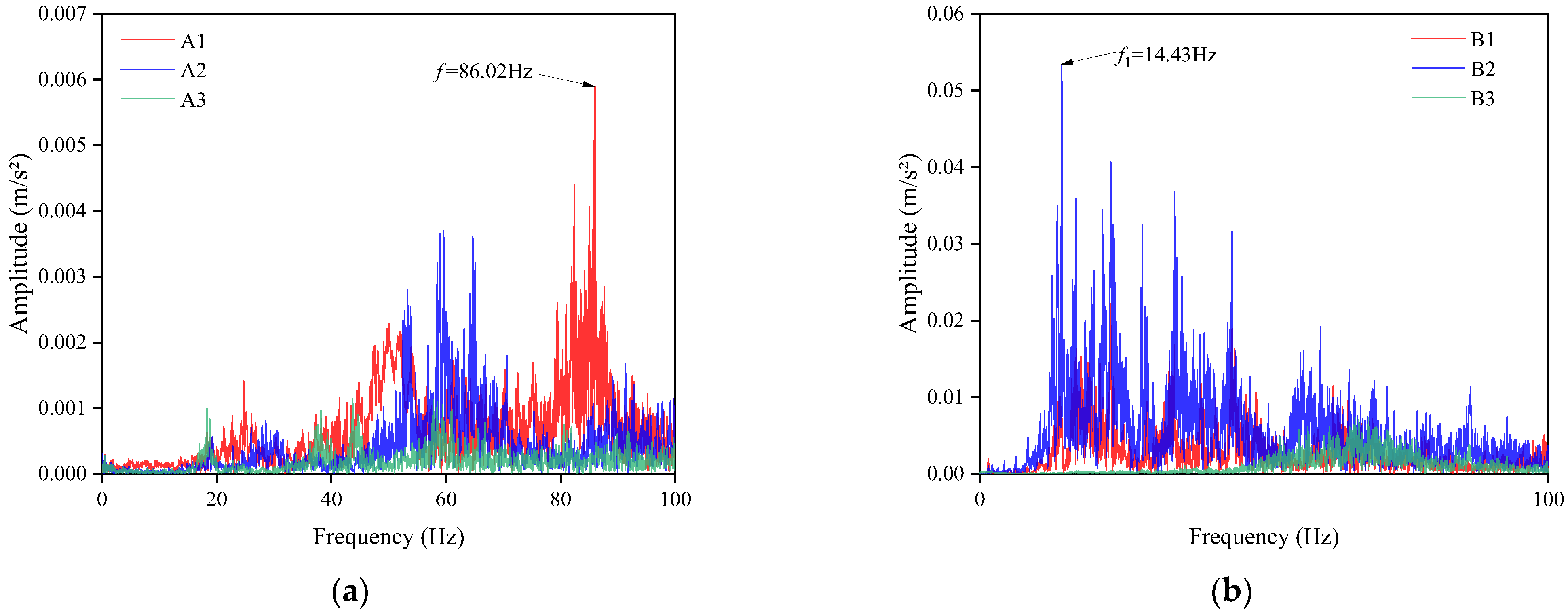
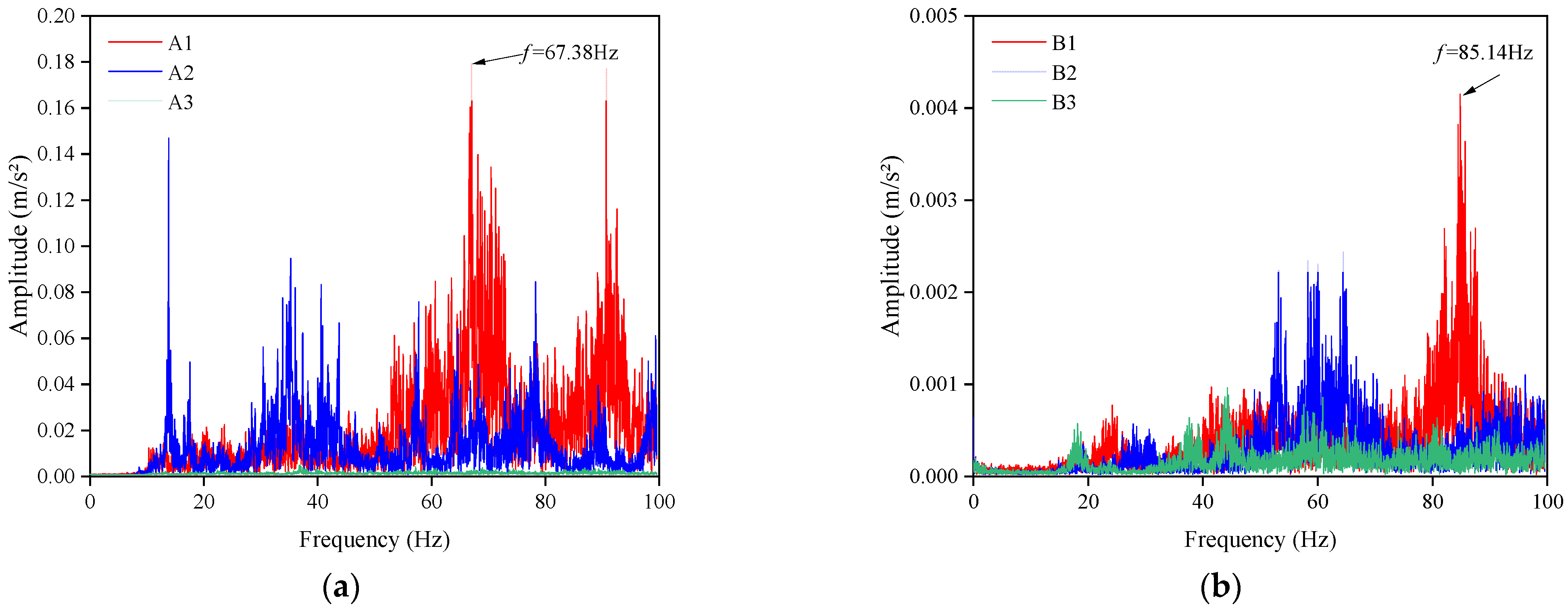
Figure 23, Figure 24 and Figure 25 present the FFT spectra of the temporary steel platform under human-induced, vehicle-induced, and combined construction excitations. The vertical and horizontal natural frequencies of the platform were 14.59 and 15.14 Hz, respectively. The dominant response frequencies were identified from the maximum-amplitude peaks in the corresponding FFT spectra. Under human-induced excitation, the dominant vertical and horizontal response frequencies were 84.32 and 20.43 Hz, respectively. These frequencies differed considerably from the corresponding natural frequencies of 14.59 and 15.14 Hz, indicating no apparent frequency matching between the dominant human-induced responses and the principal natural frequencies of the platform.
Under vehicle excitation, the dominant response frequencies were 67.38 Hz in the vertical direction and 85.14 Hz in the horizontal direction. Both frequencies were substantially higher than the corresponding natural frequencies, indicating clear frequency separation and a relatively low likelihood of resonance associated with the dominant vehicle-induced responses. Under combined construction excitation, the dominant vertical response frequency was 86.02 Hz, which remained substantially different from the vertical natural frequency. In contrast, the dominant horizontal response frequency decreased to 14.43 Hz, which was close to the horizontal natural frequency of 15.14 Hz, corresponding to a relative frequency difference of approximately 4.69%. This close frequency proximity suggests that the platform may be susceptible to dynamic amplification in the horizontal direction under combined construction excitation.
It should be noted that the dominant frequencies identified from the FFT spectra represent the primary frequency components of the measured response of the temporary steel platform rather than the excitation frequencies themselves. Therefore, the mere observation of closely spaced frequencies does not conclusively demonstrate the occurrence of resonance. Future work will involve a comprehensive analysis incorporating vibration amplitudes and structural response characteristics.

5. Conclusions

Addressing the limitations of existing temporary steel platforms, including low material utilization efficiency, complex construction procedures, and difficulties in pile installation in deep-water areas, this study proposed a novel Lightweight Temporary Steel Platform (LTSP) system based on a practical inland high-pile wharf project and investigated its dynamic response characteristics through field testing. The main conclusions are summarized as follows:
(1)
By utilizing the permanent rock-socketed steel pipe piles of the wharf structure as the load-bearing foundation, a lightweight composite structural system consisting of steel pipe piles, welded corbels, twin I-beam main girders, I-beam distribution girders, and checkered steel plate decking was developed.
(2)
A construction methodology based on the collaborative utilization of permanent and temporary structures was proposed. By directly employing the permanent pile foundation as the platform support system, the amount of temporary works was significantly reduced, resulting in improved material utilization, construction efficiency, and economic performance.
(3)
The LTSP exhibited relatively high natural frequencies, with all identified fundamental frequencies exceeding 14 Hz. The natural frequencies within the same vibration direction were well separated, indicating a low likelihood of resonance with human-induced excitation. In addition, the platform demonstrated greater lateral stiffness than vertical stiffness.
(4)
Pedestrian-induced vibrations were primarily localized near the excitation region, whereas vehicle-induced vibrations were distributed more uniformly throughout the platform. The permanent steel pipe piles provided effective local restraint and stiffness enhancement, thereby reducing vibration responses in adjacent areas.
(5)
Construction machinery generated the most significant vibration responses, particularly under combined operation conditions involving multiple pieces of equipment. The peak vibration levels recorded during combined construction activities were substantially higher than those induced by pedestrian or vehicular loading. Therefore, during the construction of this temporary steel platform, the simultaneous operation of multiple heavy construction machines—specifically, the coordinated use of rotary drilling rigs, fully loaded tanker trucks, and truck cranes under the test conditions described herein—should be minimized as much as possible to ensure the platform’s safety and serviceability.
Although a novel lightweight temporary steel platform (LTSP) system has been proposed, offering advantages such as reduced temporary works, improved material utilization, and enhanced construction efficiency and economic benefits, its findings are based on a single field application case; thus, further research is required to evaluate its applicability to other practical engineering projects. Furthermore, this study analyzed the platform’s temporary vibration response through localized on-site measurements, without comprehensive long-term monitoring. Future work could involve developing numerical models to further validate and analyze the overall vibration response of the platform.

Author Contributions

Methodology, Q.L. and F.G.; validation, H.F. and X.D.; investigation, Q.L., F.G. and Y.L.; data curation, H.D., Y.Z. and F.P.; writing—original draft preparation, Q.L., X.D., Y.W. and X.K.; writing—review and editing, F.P., Y.Z. and H.D.; supervision and project administration, F.G. All authors have read and agreed to the published version of the manuscript.

Funding

This research received no external funding.

Data Availability Statement

The data presented in this study may be available upon reasonable request.

Conflicts of Interest

Authors Qiuliang Long, Xiaolin Deng, Hongneng Fang, Yuzhao Liu, Huiyun Dai, Feng Peng, and Yi Zhou were employed by the company Hunan Harbor Engineering Co. Ltd. Authors Yuanhang Wang and Xiaolong Ke were employed by the company China construction third engineering bureau (Shenzhen) Co., Ltd. The remaining authors declare that the research was conducted in the absence of any commercial or financial relationships that could be construed as a potential conflict of interest.

References

  1. Wu, J. Technical discussion of cross-river steel trestle and steel platforms. China Highw. 2022, 16, 95–97. (In Chinese) [Google Scholar]
  2. Wang, Z. 50000 tons of crude oil pier construction steel platform design and construction in Meizhou Bay Port District. Sci. Technol. Consult. 2014, 9, 29–101. (In Chinese) [Google Scholar]
  3. Dai, L.; Liao, B. The research and application of innovative high efficient construction technologies in super high rise steel structure building. Int. J. High-Rise Build. 2014, 3, 205–214. [Google Scholar]
  4. Ashurovna, X.; Mirzayev, S. Innovative Technical Solutions in the Design of Modulle Residential Buildings. Cent. Asian J. Arts Des. 2022, 3, 1–2. [Google Scholar]
  5. Szolomicki, J.; Golasz-Szolomicka, H. Technological advances and trends in modern high-rise buildings. Buildings 2019, 9, 193. [Google Scholar] [CrossRef] [Scilit]
  6. Jiang, S.; Zhu, D.; Liu, Y.; Ma, L.; Gao, Z. Design of a New Plate Frame Steel Type Patform and Its Dynamic Response Analysis Under Wind-Wave-Current Coupling Effect. South China J. Seismol. 2024, 44, 151–158. (In Chinese) [Google Scholar]
  7. Guo, L.; Jia, M.; Li, R. Hysteretic analysis of thin steel plate shear walls. Int. J. Steel Struct. 2013, 13, 163–174. [Google Scholar] [CrossRef] [Scilit]
  8. Jiang, Y.; Meng, X. Characteristics of Steel Structures in High-Rise Buildings and Their Development and Prospects in my country. Build. Sci. Res. Sichuan 2003, 29, 31–32. (In Chinese) [Google Scholar]
  9. Du, W. Study on Structural Analysis and Construction Technology about the Large Temporary Steel Platform. Master’s Thesis, Chongqing University, Chongqing, China, 2016. [Google Scholar]
  10. Wen, Y.; Qi, H. Discussion on shield rectification technology in soft ground and hard ground. J. Shanxi Archit. 2018, 44, 181–182. (In Chinese) [Google Scholar]
  11. Wang, A.; Zhang, K. Structure Design of Steel Casing Platform for Construction of Pile Foundation in Water. Road Mach. Constr. Mech. 2018, 35, 63–67. [Google Scholar]
  12. Rhee, J.; Nguyen, H.; Kim, M.; Lim, Y.; Kim, G. An integrated machine-learning platform for assessing various dynamic responses of steel beams. Structures 2024, 61, 106125. [Google Scholar] [CrossRef] [Scilit]
  13. Mazaheri, P.; Asgarian, B.; Gholami, H. Assessment of strengthening, modification, and repair techniques for aging fixed offshore steel platforms. Appl. Ocean Res. 2021, 110, 102612. [Google Scholar] [CrossRef] [Scilit]
  14. Xiang, G. Research on the Safety Status Assessment Method of Dock Steel Platform Structure Based on Machine Vision. Master’s Thesis, Chongqing Jiaotong University, Chongqing, China, 2025. [Google Scholar]
  15. Ruan, Z. Strength and Stability Calculation of Drilled Steel Platform for High—Piled Wharf. Technol. Highw. Transp. 2017, 33, 52–54. [Google Scholar]
  16. JTS 167-2018; Wharf Structure Design Code. China Communications Press: Beijing, China, 2018. (In Chinese)
  17. JGJ 7-2010; Technical Specification for Space Grid Structure, Industrial Standard of the People’s Republic of China. Architecture and Building Press: Beijing, China, 2010. (In Chinese)
  18. Yu, Y.; Nie, X.; Liu, J.; Wang, X.; Hu, S. Vibration serviceability of light weight steel modular floor: Experimental test and assessment. Eng. Struct. 2025, 343, 121253. [Google Scholar] [CrossRef] [Scilit]
  19. Lacey, A.; Chen, W.; Hao, H.; Bi, K. Structural response of modular buildings—An overview. J. Build. Eng. 2018, 16, 45–56. [Google Scholar] [CrossRef] [Scilit]
  20. Genser, A.; Spielhofer, R.; Nitsche, P.; Kouvelas, A. Ride comfort assessment for automated vehicles utilizing a road surface model and Monte Carlo simulations. Comput.-Aided Civ. Infrastruct. Eng. 2022, 37, 1316–1334. [Google Scholar] [CrossRef] [Scilit]
  21. ISO2631-1:1997; Mechanical Vibration and Shock-Evaluation of Human Exposure to Whole-Body Vibration Part 1: General Requirements. International Organization for Standardization: Geneva, Switzerland, 1997.
  22. López-Cuervo, A.S.; García-Macías, E.; Chiachío, J. Full-scale validation of operational modal analysis using strain gauges in steel civil structures with optimized sensor layouts. Measurement 2026, 281, 121916. [Google Scholar] [CrossRef] [Scilit]
  23. Zhao, J.; Sun, F.; Yang, S.; Yin, W.; Xu, Z.; He, S. Modal characteristics of vertical vibration in typical steel frame structures under road traffic loads: Actual measurements and finite element model update. J. Build. Eng. 2025, 111, 113346. [Google Scholar] [CrossRef] [Scilit]
Figure 1. Lightweight temporary steel platform. (a) Overview diagram; (b) Detail drawing.
Buildings 16 03528 g001
Figure 2. Construction Process for a lightweight temporary steel platform. (a) Tie beam welding; (b) Corbel welding; (c) Main beam erection; (d) Secondary beam erection; (e) Steel plate installation; (f) Removal of panels and beams.
Buildings 16 03528 g002
Figure 3. The actual construction site of LTSP. (a) Permanent steel pile foundation; (b) Erection of temporary steel platforms.
Buildings 16 03528 g003
Figure 4. Overall calculation model of the lightweight temporary steel platform.
Buildings 16 03528 g004
Figure 5. Calculation results for the components of the LTSP. (a) Main beam; (b) Secondary beam; (c) Corbel.
Buildings 16 03528 g005
Figure 6. Test area and sensor layout.
Buildings 16 03528 g006
Figure 7. Test site instrumentation layout. (a) Sensor layout; (b) YSV dynamic data acquisition instrument.
Buildings 16 03528 g007
Figure 8. Specific test content. (a) Single pedestrian; (b) Three pedestrians; (c) Empty Tanker; (d) Fully Loaded Tanker; (e) Rotary Drilling Operation Condition; (f) Collaborative Construction.
Buildings 16 03528 g008
Figure 9. Acceleration time curves at the measurement point under natural environmental conditions. (a) Vertical acceleration; (b) Horizontal acceleration.
Buildings 16 03528 g009
Figure 10. Acceleration amplitude spectrum. (a) Vertical; (b) Horizontal.
Buildings 16 03528 g010
Figure 11. Acceleration time-history response under single pedestrian walking excitation. (a) Vertical acceleration; (b) Horizontal acceleration.
Buildings 16 03528 g011
Figure 12. Acceleration time-history response under three pedestrians walking excitation. (a) Vertical acceleration; (b) Horizontal acceleration.
Buildings 16 03528 g012
Figure 13. Acceleration time-history response under five pedestrians walking excitation. (a) Vertical acceleration; (b) Horizontal acceleration.
Buildings 16 03528 g013
Figure 14. RMS acceleration time-history curves under pedestrian excitation. (a) Vertical acceleration A1; (b) Horizontal acceleration B1.
Buildings 16 03528 g014
Figure 15. Acceleration time-history curves under driving conditions (Empty tanker). (a) Vertical acceleration; (b) Horizontal acceleration.
Buildings 16 03528 g015
Figure 16. Acceleration time-history curves under driving conditions (Fully loaded tanker). (a) Vertical acceleration; (b) Horizontal acceleration.
Buildings 16 03528 g016
Figure 17. RMS acceleration time-history curves under driving conditions (Empty tanker). (a) Vertical acceleration; (b) Horizontal acceleration.
Buildings 16 03528 g017
Figure 18. RMS acceleration time-history curves under driving conditions (Fully loaded tanker). (a) Vertical acceleration; (b) Horizontal acceleration.
Buildings 16 03528 g018
Figure 19. Acceleration time-history curves under construction conditions (Rotary drilling operation condition). (a) Vertical acceleration; (b) Horizontal acceleration.
Buildings 16 03528 g019
Figure 20. RMS acceleration time-history curves under construction conditions (Rotary drilling operation condition). (a) Vertical acceleration; (b) Horizontal acceleration.
Buildings 16 03528 g020
Figure 21. Acceleration time-history curves under construction conditions (Collaborative construction). (a) Vertical acceleration; (b) Horizontal acceleration.
Buildings 16 03528 g021
Figure 22. RMS acceleration time-history curves under construction conditions (Collaborative construction). (a) Vertical acceleration; (b) Horizontal acceleration.
Buildings 16 03528 g022
Figure 23. Acceleration amplitude spectra under the excitation of five pedestrians walking. (a) Vertical; (b) Horizontal.
Buildings 16 03528 g023
Figure 24. Acceleration amplitude spectra under driving conditions (Fully loaded tanker). (a) Vertical; (b) Horizontal.
Buildings 16 03528 g024
Figure 25. Acceleration amplitude spectra under construction conditions (Collaborative construction). (a) Vertical; (b) Horizontal.
Buildings 16 03528 g025
Table 1. Performance analysis of existing temporary construction steel platform structures.
Steel Platform TypesStructural CompositionLimitations of Wharf Construction
Assembled Bailey truss steel platformA structural system comprising steel pipe piles, corbels, main beams, Bailey trusses, and distribution beams.The system features complex construction, numerous connection nodes, relatively high self-weight, and stringent requirements for construction organization.
Integrated steel trestle and steel platform systemSteel trestle bridge: the substructure consists of load-bearing beams, and the superstructure is formed by assembled Bailey truss units.
Steel platform: composed of steel pipe piles, connection components and bracing systems, corbels, steel transverse beams, Bailey trusses, distribution beams, and steel deck plates.
The platform exhibits limited structural stiffness, imposes constraints on the deployment of heavy-duty equipment, and demonstrates insufficient long-term stability.
Simple steel pipe pile support platformSteel pipe piles, main beams, distribution beams, and steel plate decking.Limited load-bearing capacity; overall stability depends on dense pile arrangements; relatively poor scour resistance.
Platform with traditional steel pipe piles and structural steel beam systemSteel pipe pile supports, lateral steel members, longitudinal steel members, thick timber planks, and guardrails; the steel pipe piles are interconnected through transverse members and diagonal bracing.High dependency on geological conditions, high construction costs and resource wastage, and room for improvement in borehole formation precision.
Table 2. Material quantities and properties of the lightweight temporary steel platform.
Type of Steel UsedQuantityUnit Weight/kgSteel GradeElastic Modulus/GPaYield Strength/MPaPoisson’s Ratio
Steel Corbel 1332168Q235B2062350.3
2I45a × 31,000104964.34
2I45a × 27,0001884323.78
2I45a × 13,20082113.85
2I45a × 25,50044083.57
2I45a × 20,00023202.80
2I45a × 34,50085524.83
2I45a × 24,00043843.36
2I45a × 22,00043523.08
2I45a × 15,50022482.17
I32a × 758,0008139,926.51
I32a × 35,550141872.54
I32a × 68001916358.18
I32a × 3700216194.89
I32a × 25,000391316.84
I32a × 590033310.77
Table 3. Calculation results for the components of the lightweight temporary steel platform.
ComponentMain BeamSecondary BeamCorbelCheckered Steel PlatePermanent Pile Foundations
Bending stress/MPaCalculated value192.3183.6212.8140.6Pile foundation stability: 0.191 < 1; Single-pile bearing capacity: 2646 kN > 1097 kN
Permissible value215215215215
Shear stress/MPaCalculated value7149110.25.6
Permissible value125125125125
Displacement/mmCalculated value9.815.5//
Permissible valueL/200L/400//
Weld stress/MPaCalculated value//60/
Permissible value//195.2/
Table 4. Detailed test plan for dynamic excitation testing of the LTSP.
NumberOperating ConditionsSpecificVehicle Weight (kg)
1Ambient excitation//
2Human-induced walking conditionsSingle pedestrian70
3Three pedestrians210
4Five pedestrians350
5Driving conditionsEmpty tanker31,000
6Fully loaded tanker45,000
7Construction conditionsRotary drilling operation condition400,000
8Collaborative construction/
Table 5. Peak root-mean-square (RMS) acceleration values under different test conditions.
Operating ConditionsSpecificNumberPeak RMS Acceleration Values (m/s2)Mean ResultsStandard Deviation
A1B1A1B1A1B1
Human-induced walking conditionsSingle pedestrian10.3320.0540.3640.0590.0320.006
20.3960.065
30.3640.058
Three pedestrians10.4470.0940.4540.0810.0600.012
20.5170.070
30.3980.079
Five pedestrians10.3820.0900.4930.0920.1130.022
20.6080.071
30.4890.115
Driving conditionsEmpty tanker11.0450.3151.1100.2900.0660.025
21.1770.289
31.1080.266
Fully loaded tanker11.5050.3691.6500.3700.1460.051
21.6480.421
31.7970.320
Construction conditionsRotary drilling operation condition12.6500.5003.0230.5040.3770.076
23.4040.430
33.0150.582
Collaborative construction14.5820.5153.7740.6510.8010.138
22.9800.790
33.7600.648
Disclaimer/Publisher’s Note: The statements, opinions and data contained in all publications are solely those of the individual author(s) and contributor(s) and not of MDPI and/or the editor(s). MDPI and/or the editor(s) disclaim responsibility for any injury to people or property resulting from any ideas, methods, instructions or products referred to in the content.