Article

Enhanced Earthquake Performance of Existing RC Buildings Through Hybrid CFRP and Damper Retrofitting

by
Hakan Koman
* and
Abdullah Niğdelioğlu
Department of Civil Engineering, Engineering Faculty, Istanbul Aydın University, Kucukcekmece 34295, Türkiye
*
Author to whom correspondence should be addressed.
Buildings 2026, 16(14), 2825; https://doi.org/10.3390/buildings16142825
Submission received: 22 May 2026 / Revised: 4 July 2026 / Accepted: 13 July 2026 / Published: 16 July 2026
(This article belongs to the Special Issue Seismic Analysis and Design of Building Structures—2nd Edition)

Abstract

Interest in applying hybrid retrofitting approaches to existing buildings is steadily increasing. In this study, an attempt was made to seismically retrofit an RC (reinforced concrete) building using CFRP (carbon fiber-reinforced polymer) and dampers. For this purpose, nonlinear time history analysis was performed. The placement of dampers in the RC frame required the use of panels. Panels do not interact with columns; however, the interaction between the panels and the beams was considered. First, the behavior of a single-story RC frame with panels was numerically analyzed using Abaqus 2017. Then, a typical old RC building was modeled in SAP2000 v26 under three configurations: its existing condition with hollow brick infill walls, a CFRP-retrofitted condition, and a condition retrofitted with a hybrid CFRP–damper system, in which lightweight concrete panels replaced the hollow brick infill walls. When the results were compared, the hybrid retrofitting approach with CFRP and Idrizi dampers reduced story displacement by 41.13–42.70% in the X direction and by 32.74–46.89% in the Y direction, on average. Base shear forces were reduced by approximately 31–33% in the X direction and 6–9% in the Y direction. Improvements were also observed in beam plastic hinge conditions. Thus, the hybrid approach was found effective for seismic retrofitting.

1. Introduction

In the past, destructive earthquakes such as Northridge (1994), Landers (1992), Duzce (1999), and Kahramanmaras (2023) severely damaged cities around the globe. Problematic building stocks, consisting of non-ductile moment frame RC (reinforced concrete) structures, are prevalent, especially in developing countries. Using insufficient confinement rebar in plastic hinge regions is common. Thus, practical retrofitting methods are needed to prepare cities against strong ground motions. In a previous experimental study, two full-scale identical RC buildings, representative of Türkiye’s problematic building stock, were subjected to lateral loading. One of the buildings was strengthened using CFRP wrap on the first-story columns. The non-retrofitted building collapsed due to columns’ shear failure at a 0.0135 drift ratio, whereas the retrofitted one did not collapse even at a 0.15 drift ratio [1]. In another study, a CFRP wrap was first applied to RC columns, and the behavior was observed both experimentally and numerically. The CFRP wrap increased members’ lateral load capacity by 10.39% to 14.87%, depending on the number of CFRP layers, and ductility was also increased [2]. Later, an RC building was modeled in the Sap2000 v15 software, and a pushover analysis was conducted. According to the results, five layers of CFRP wrap increased the capacity of the modeled structures, and the damage index decreased by 30% [2].
Importantly, infill walls—which have not been taken into consideration for structural analysis—change the stiffness of structures, causing soft stories or torsional irregularities. According to Eurocode 8, infill walls must be included in the modeling of structures and the irregularity analysis; however, rather than determining specific rules, freedom was given to designers [3]. Unlike Eurocode 8, FEMA 356 code determines a method for the modeling of infill walls as equivalent compressive struts inside the frame if a more detailed FEM analysis was not performed [3]. In this approach, the equivalent strut has the same thickness and modulus of elasticity as the infill wall, as indicated in a past study [4]. The effect of infill walls can be positive or negative based on their placement and distribution inside the structure. A proper distribution of infill walls can increase the lateral stiffness of a problematic structure but, in a problematic building, if the infill wall distribution causes torsional irregularity, then the possibility of shear failure of columns will increase.
Ceasing the interaction of infill walls with frames using flexible materials can eliminate problems. In a previous study, RC frames containing infill walls were analyzed using the Sap2000software. According to the results, the usage of polyurethane flexible joints between frames and walls decreases frequency and increases ductility when compared with a counterpart containing stiff joints; even if damage occurs to the frame, the data showed how infill walls provided a reserve capacity in maintaining the overall stability of the structure [5].
In modern seismic design philosophy, increasing the energy dissipation in the structure is vital; thus, seismic dampers are used. Previous research evaluated the effectiveness of three metallic dampers placed between beams and diagonal members in steel and RC buildings. Among those tested, the hybrid MYFD (metallic yielding friction damper) proved the most effective at dissipating energy. For RC structures, the application of MYFDs resulted in a nearly 35% reduction in displacement [6]. In another study, a comb-teeth damper, a frictional damper, and a hybrid comb-teeth friction-type damper (CTFD) were tested experimentally and numerically, and the behavior was analyzed [7]. Then, different RC hospital models with different configurations of dampers were modeled, and nonlinear time history analysis was performed. According to the results, the CTFD demonstrated excellent energy dissipation capacity at approximately 75% and 25% higher than that of the comb-teeth damper (CTD) and friction damper (FD), respectively, and the hybrid system achieved nearly 80% total energy dissipation, maintained inter-story drift ratios within 0.002, and reduced top displacement by about 60% compared to the uncontrolled frame [7]. In another study, fluid viscous dampers (FVDs) were used in the model of a 14-story RC structure; a response spectrum analysis was performed, and the behavior was compared with the RC shear wall alternative [8]. In terms of story displacements, FVDs placed at the corners achieved a 14.73% reduction in the X direction and a 41.34% reduction in the Y direction. The effectiveness of dampers, though lesser than that of shear walls, lies in their energy-dissipating capability rather than stiffness enhancement [8]. In another experimental study, a new type of wall system consisting of Idrizi seismic dampers and infill walls was proposed, and via the application of quasi-static lateral loading, the behavior of the damper was determined [9]. Later, Idrizi dampers were modeled inside an RC building, and analysis was performed using Sap2000 v14 in another study [10]. The effect of infill walls has also been taken into consideration by modeling them as equivalent struts, and Idrizi devices were also modeled using link elements in Sap2000 v14. According to the results, in the X direction, top lateral displacements were reduced from 17.5 cm to 14 cm due to the Idrizi devices when the behavior was compared with the RC structure with infill walls [10]. It was concluded that by using Idrizi dampers, depending on the structural type of buildings, improvements in strength and ductility levels must be expected [10]. In another previous study, a polyurethane flexible joint was used to cease the interaction of a lightweight concrete panel with an RC frame, and metallic dampers were placed between the panel and the frame [11]. According to the numerical analysis performed using Abaqus [11,12], the proposed panel with dampers increased the lateral stiffness, capacity, and energy dissipation of RC frames.
In this study, a hybrid seismic retrofitting method was proposed. The proposed method aimed to prevent shear failure of columns, eliminate the problems caused by the interaction of infill walls and the RC frame, and increase the energy dissipation of the structure using cost-effective and innovative dampers. Although the effect of CFRP wrapping of columns is well known, the combined effect of damper application inside an RC structure with innovative lightweight panels alongside CFRP-strengthened members has not been sufficiently explored through nonlinear time history analysis. Unlike traditional methods, the proposed method, thanks to the special design of the Idrizi-type damper, allows for the application of dampers without the need for additional steel braces. This enables direct mounting inside the lightweight concrete panel wall system, thus meeting architectural requirements. The proposed system with lightweight panels and dampers was investigated only in single-story RC frames through quasi-static loading in Abaqus 6.13 previously [11]; thus, an investigation of this method was needed for multi-story frames. The previous study [11] did not consider the effect of the proposed wall system without any dampers. However, for the analysis of a multi-story structure, understanding the effect is needed. First, the effect of a lightweight panel without any dampers was analyzed using 3D elements in Abaqus 2017 and beam and link elements in Sap2000 v26. Later, 3-story structures were modeled in Sap2000 v26 and nonlinear time history analysis was performed to understand the effect of the proposed hybrid retrofitting system by comparing the behavior of a bare structure containing no walls, a structure containing walls, and a structure containing the proposed walls with Idrizi dampers and lightweight panels.

2. Methodology

2.1. Abaqus Modeling of Single-Story Frames

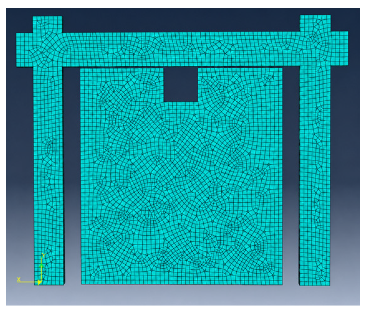
The RC frame in this study was taken from previous experimental and numerical studies [11,13,14]. Inside the RC frame, there is a lightweight concrete panel that is separated from the beam by a polyurethane binder. However, in a previous numerical study [11], the effect of the panel on the frame was not clear. To reveal the behavior, the panel was modeled inside the RC frame again. By following the method of previous numerical studies [11,13], the structural materials were assumed to be European materials. The Abaqus 2017 model consists of a full-scale, single-story RC frame. The dimensions of frame members and the rebar can be seen in the previous studies [11,13,14]. To streamline the numerical process, column bases were modeled as fixed supports under a constant axial load of 700 kN (5.71 MPa) [11,12]. The Abaqus 2017 model of the frame is shown in Figure 1.
Further details regarding Abaqus 2017 modeling, such as mesh size, element type, and the details of explicit dynamic analysis, can be found in previous studies [11,13]. A displacement-controlled explicit dynamic analysis was conducted, reaching a lateral drift of 80 mm.
For modeling of the concrete, the CDP (Concrete Damaged Plasticity) model was used. The plasticity parameters of the concrete were as follows: a dilation angle of 38°, a flow potential eccentricity of 0.1, and a biaxial to uniaxial compressive strength ratio of 1.16 [11,13]. The modulus of elasticity was taken as 31,000 MPa [11,13], and to obtain stress–strain relationships, Equation (1), taken from a previous study, was used [15]:
f f 0 = 2.1 ɛ ɛ 0 1.33 ɛ ɛ 0 2 + 0.2 ( ɛ ɛ 0 ) 3
In Equation (1), f0 is the cubic strength of concrete (30 MPa), ɛ0 is 0.0022, and ɛmax is 0.0035. Tensile behavior was idealized as linear until the tensile strength limit (3.83 MPa) was reached, which was derived from the characteristic compressive strength. For the post-peak regime, an exponential softening response was defined to simulate the degradation of structural integrity beyond the elastic limit [11,13]. In Abaqus, the scalar damage variables (dc and dt) for both compression and tension were taken as zero. Consequently, the constitutive model represents a purely plastic response for the post-peak regime. Setting scalar damage variables to zero does not automatically eliminate concrete’s softening behavior; rather, what is omitted by setting these variables to zero is simply the damage-induced degradation of the elastic reloading stiffness. Therefore, this approach did not affect the validation of the ultimate capacity, as good agreement between experimental curves and numerical curves was observed in past studies [11,13].
The panel was modeled using high-strength, steel fiber-reinforced lightweight concrete, previously developed using expanded clay aggregates [16]. The lightweight concrete has a compressive strength of 85.4 MPa and a tensile strength of 11.8 MPa. The concrete density was measured at 1966 kg/m3. The elastic modulus was determined to be 28,000 MPa based on the formulation provided in the reference study [16], and Poisson’s ratio was set to 0.16. For the CDP parameters, conventional assumptions for ordinary concrete were repeated. The compressive stress–strain behavior was characterized using the Hognestad model, with the strain corresponding to the peak compressive stress assumed to be 0.0022. Strain hardening was considered when modeling steel materials. The details can be seen in the previous research [11].
A polyurethane binder was applied in the interaction zone of the lightweight concrete panel and beam with a thickness of 10 mm. The polyurethane binder is a rubber-like material; thus, it is modeled as a hyperelastic material. The behavior was modeled using Mooney–Rivlin theory, which is based on defining a strain energy function. The tensile strength, modulus of elasticity, and elongation capacity of polyurethane are 1.4 MPa, 4 MPa, and 140%, respectively [17]. The Mooney–Rivlin coefficients C01 and C10 for polyurethane were taken as −0.05 and 0.47 based on an experimental study [18]. The details of Mooney–Rivlin theory can be found in the reference study [13].
In Abaqus 2017, surface-based cohesive behavior can be used to capture the traction–separation behavior between surfaces. In this approach, during traction–separation, linear behavior was assumed for the initial loading of the joint with a stiffness of Kn, Ks, or Kt (depending on whether it is loaded in the normal direction or the shear direction), and after reaching the maximum strength, a linear or exponential degradation of strength was assumed. In this study, the Kn, Ks, and Kt values were taken as 0.33 N/mm3 and 0.088 N/mm3, respectively, based on previous studies [13,19]. Fracture energy values were implemented in Abaqus 2017 to define the damage evaluation of the joint. For tension and shear failure, fracture energies were taken as 4.22 N/mm and 10.93 N/mm, respectively, based on previous studies [13,19]. To consider mixed-mode behavior, the Benzeggagh–Kenane rule was implemented.

2.2. Sap2000 Modeling of Single Story Frames

The RC frame was modeled using beam elements in Sap2000 v26. A nonlinear incremental static loading procedure (pushover analysis) was applied to determine the lateral capacity. In the modeling of the RC frame, nonlinear behavior was simulated using plastic hinges in column–beam conjunction zones where damage is expected. To achieve this, moment curvature relationships of the RC sections were obtained using the section designer menu inside the software. The section designer menu allows fiber modeling of a cross-section. The fiber modeling approach involves dividing structural sections into a finite number of fibers, tailored to the section’s geometry. Each fiber is defined by its cross-sectional area and local coordinates. In RC sections, fibers are assigned distinct material properties for concrete and steel, unlike homogeneous sections. The response of the entire section is integrated from the constitutive laws of individual fibers. For the definition of column hinge, the interaction between axial load and flexural capacity in the columns was also considered in the fiber model. Plastic hinges were assumed to form at locations corresponding to 10% and 90% of the member length from each end. The hinge length was assumed to be 10% of the total member length.
In the interaction zone between the panel and beam, shear deformations occur, and the lateral load capacity slightly increases. Thus, the effect of the panel inside the frame was considered using two link elements between the beam and the base of the frame. The link was considered the multi-linear plastic type. The effective stiffness was calculated as 2.67 kN/mm by considering the shear modulus of polyurethane (1.33 MPa), the area of the joint (20,000 mm2), and the thickness of the joint (10 mm). Its strength is calculated as 20 kN based on the area (20,000 mm2) of the joint and the strength of the joint. In a previous study [19], the shear strength of joints with polyurethane was determined to be around 1 MPa on average. The load linearly increases to 20 kN at 12.5 mm displacement. After the peak load, the strength was assumed to degrade linearly to 2 kN at 20 mm displacement. The kinematic hysteresis type was selected. In the vertical direction, to represent the combined axial stiffness, a series spring model was adopted, where the effective stiffness was derived from the individual stiffnesses of the polyurethane and lightweight concrete. The effective stiffness of the link was 8 kN/mm. The model accounts for the initial soft response dominated by the polyurethane, followed by the hardening phase as the material reaches its crushing limit, after which the stiffness transitions to that of the concrete panel. From a previous study [19], the compressive strength of the polyurethane joint was determined to be 10 MPa on average. Based on the area (20,000 mm2) and compressive strength of the joint was determined as 200 kN for the polyurethane layer in the vertical direction. For the lightweight concrete layer, the compressive strength was determined as 1400 kN.

2.3. Validation of Single Story Frame Analysis

As seen in the previous studies [11,13,20], Abaqus analysis of the bare frame without any walls was compared with the previous experimental study [14], and good agreement was detected. Later, Sap2000 v26 modeling was compared with Abaqus 2017, and good agreement was observed [13,20]. The method applied for the analysis is different in Sap2000 v26 and Abaqus 2017. The analysis in Sap2000 v26 (macro-model) takes into consideration simplified representations of the effect of the infill wall by representing them as lumped elements or structural struts, resulting in a stiff load path that will attain its peak capacity earlier. The Abaqus (micro-model), on the other hand, considers 3D continuum contact formulation, stress concentrations, and softening of material and interfaces. This phenomenon was detected in a previous study [20], in which RC frames with and without infill walls were modeled.
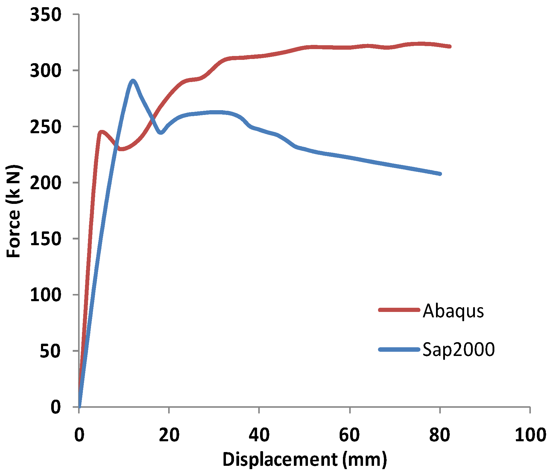
In that study, the Abaqus analysis of the frame and the proposed panel was compared with Sap2000 v26 modeling. In Abaqus, the lateral load capacity of the RC frame with panels was 322.45 kN. When compared with a bare frame, which has a capacity of 271.75 kN [13], the panels provided a 18% increase in the capacity. In Sap2000 v26, the bare frame carried 227.3 kN [13], whereas the frame with panels carried 289.77 kN. The discrepancy between the Abaqus analysis and the Sap2000 v26 analysis is around 10%. However, again, the peak response is shifted to a larger displacement in Abaqus. RC frame and polyurethane are modeled using 3D elements, and the complex interaction between the panel and polyurethane binder is modeled using surface-based cohesive behavior in Abaqus. This allows Abaqus to capture the effect of beam bending during interaction. Also, Abaqus captures multi-axial localized stress gradients and progressive, non-uniform contact softening via “cohesive surface damage evolution” along the interface. This continuous stress redistribution gradually reduces the pre-peak stiffness, realistically delaying the peak force to a displacement of 26 mm. In Sap2000 v26, the beam and panel interaction is modeled using discrete, uncoupled nonlinear link elements at specific nodal locations. When the frame deforms, these discrete links reach their ultimate capacity and yield simultaneously, which captures the ultimate force at an early stage (16 mm). The 10% agreement in ultimate force capacity successfully validates the strength prediction of both models. The results can be seen in Figure 2.

2.4. Modeling of Multistory Building

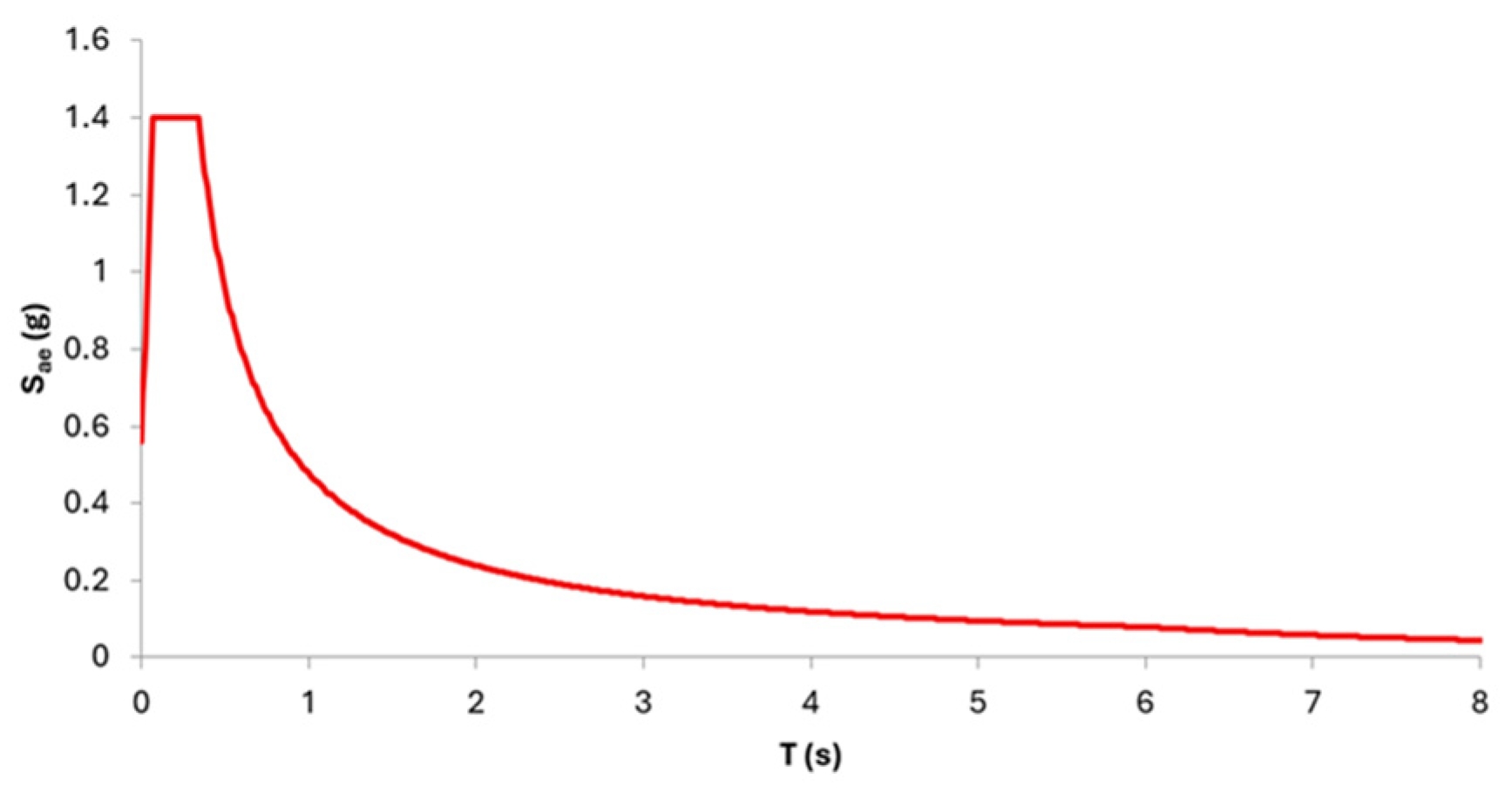
Within the scope of the study, nonlinear time history analyses were performed (Direct Integration Method). P-Delta effects were taken into consideration in the study. A damping ratio of 5% was assumed for the building. A 3-story residential building, which was designed according to the codes of 70 s, was selected from a previous study [21]. The building considered in this study is located at latitude 40.994334° and longitude 28.797354°, and the local soil class at the construction site is ZC, corresponding to dense sand or gravel. The DD-2 earthquake ground motion was selected in accordance with TBEC-2018 [22], which had a 10% probability of exceedance in 50 years or, in other words, a return period of 475 years, and was defined as the standard design earthquake. Figure 3 shows the horizontal elastic design spectrum. Column dimensions are 30–50 cm, and beam dimensions are 20 cm × 50 cm. There are two types of rebar configuration in beams. In type 1, most of the beams contain 3ϕ12 at the bottom of the cross-section and 2ϕ12 at the top of the cross-section. In the second type, 2ϕ12 exists at the top and bottom of the cross-section. Columns include 6ϕ16. The story height is 2.80 m.
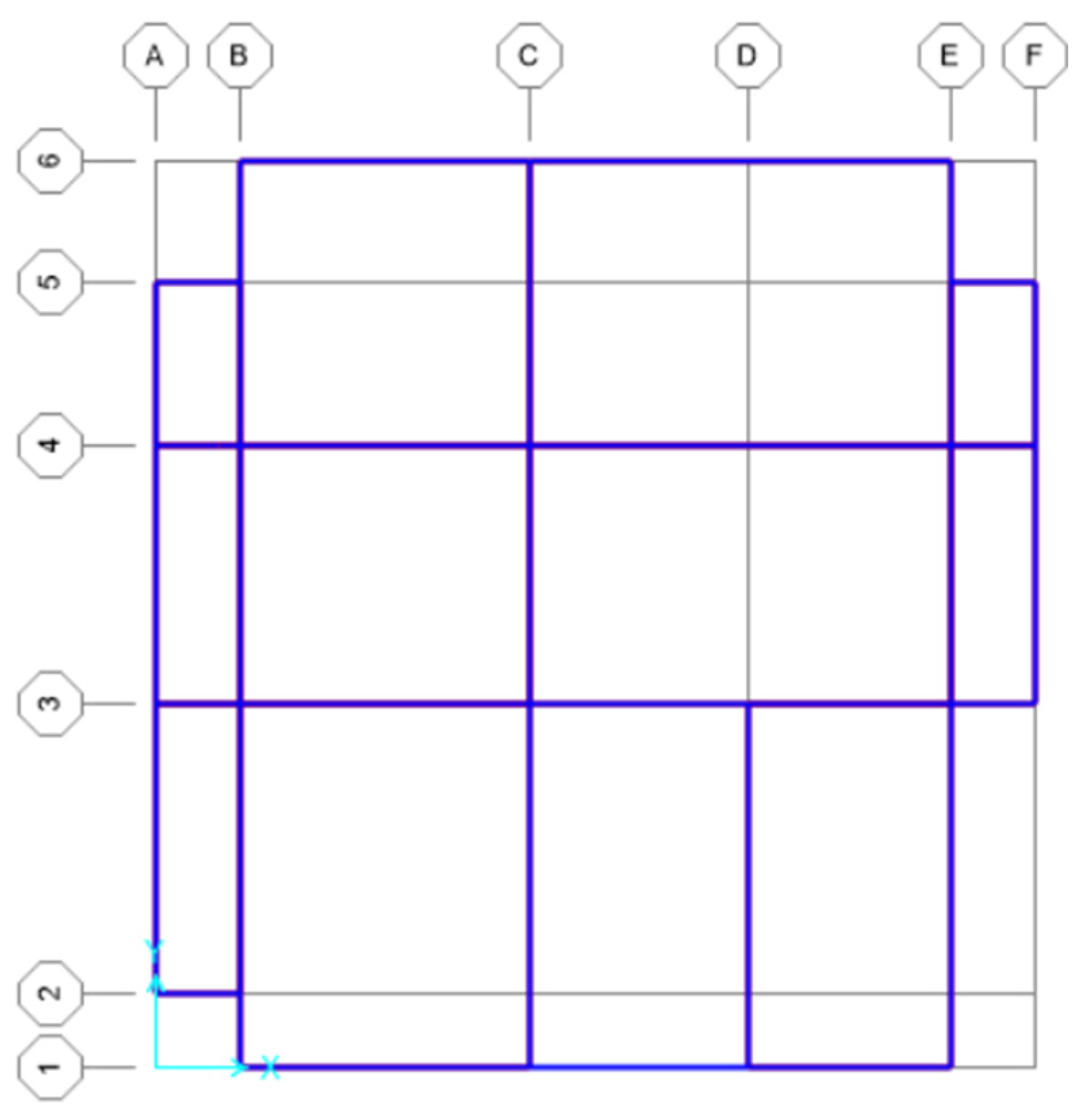
The area of the first story is 150 m2. The concrete class is C20/25, and the yield strength of steel for rebar is 420 MPa. The plan of a normal story in structure can be seen in Figure 4. A normal story includes two cantilever parts for balconies (between axis A–B and axis E–F) [21].
The structure was assumed to be a representative structure for the problematic building stock of Türkiye. One of the major problems observed in Türkiye is that shear safety is not ensured due to the large spacing of stirrups [23]. Thus, insufficient confinement rebar were used in column–beam conjunction zones (ϕ8/20 cm). For architectural purposes, some frames were assumed to have no walls. In the Y direction, inside the frames of axis B and inside the frames of axis E, between axes 3–6, no infill was considered. In the X direction, inside the frame of axis 1 between axis C–D and inside the frame of axis 3 between axis D–E, no infill wall was considered.
A 4.5 kN/m2 dead load and a 2 kN/m2 live load were applied to the slabs of a normal story. A 10 kN/m uniformly distributed load was applied to the beams where infill walls exist. On the roof, a 2 kN/m uniform load was applied to the beams where parapets exist.
The columns and beams of the structure were modeled using beam elements, and the slabs were modeled using shell elements inside the software. Similarly to single-story frame analysis, plastic hinges were defined and assigned to the ends of columns and beams. To define plastic hinges, using the section designer menu, the moment capacity was determined. For instance, for a beam with type 1 rebar configuration, 63.5 kNm and 42.9 kNm moment capacities were calculated at a curvature value of 1.026 × 10⁻⁶. Hinge length was assumed to be 10% of member length. The FEMA-356 code [24] describes curvature levels to define the performance status of plastic hinges. Point B represents yielding. Beyond this point, the code identifies specific performance criteria, namely immediate occupancy (IO), life safety (LS), and collapse prevention (CP).
In Sap2000 v26 plastic hinge definition was achieved using the FEMA approach. The moment capacity of the cross-section is used to define point B. In Sap2000 v26, beyond point B, ratios of moment to yield moment and ratios of plastic deformation to yield deformation were needed by the software. For columns, the moment curvature relationship is dependent on the axial force level of the column; thus, using 5 different axial force levels and 3 different angles, moment curvature relationships were defined for hinges. For life safety and collapse prevention levels, 0.0183 and 0.0244 values were calculated, respectively. To define the 3D interaction surface for columns, the ACI 318 (American Concrete Institute) method was used in software. In the ACI 318 method, for different axial force levels, the moment capacity of the cross-section was derived by neglecting the tensile strength of concrete. The safety coefficient was implemented as 1 to capture the real capacity of the cross-section.
As explained in the Introduction, infill walls inside RC frames are commonly modeled as equivalent compressive struts. In Sap2000 v26, link elements were used for this purpose.
The link elements were characterized as multi-linear plastic links. The methodology was explained in previous studies [25,26]. These struts were numerically represented using a hysteretic pivot model. The equations used in the modeling of hysteretic pivot links are presented as follows [13,25,26]:
λ 1 = E w i n f t w i n f sin 2 . θ 4 . E c m I c h w i n f 4
b w i n f = 0.175 r w i n f ( λ 1 . l c ) 0.4
In Equations (2) and (3), Ewinf is the elastic modulus of the infill wall, twinf is the thickness of the equivalent strut, θ indicates the aspect ratio, Ecm is the modulus of elasticity of the material used in the frame system, Ic is the moment of inertia of the columns, and hwinf is the height of the infill panel, rwinf represents the diagonal length of the infill wall panel, and lc is the height of the columns. The modulus of elasticity of the infill wall was obtained as 1012 MPa in a previous study using the following equation [27]:
E = ( t t + t h ) t t E t + t h E h
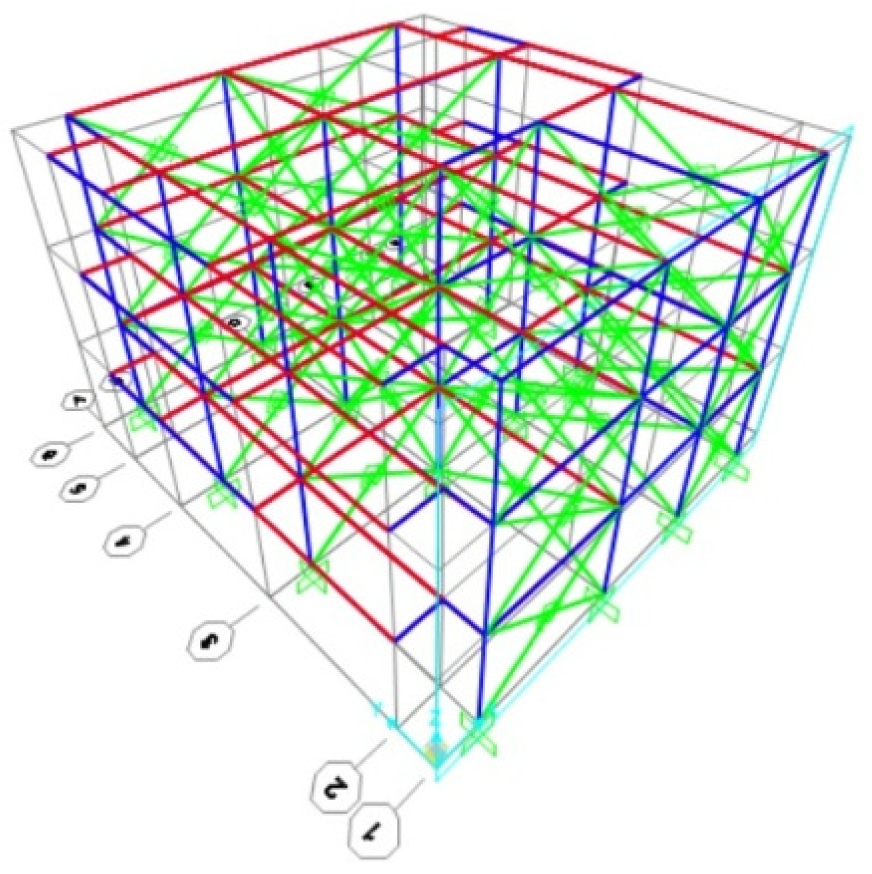
In Equation (4), th, tt, Eh, Et, k, and E are the thickness of the mortar, thickness of the hollow brick, Young’s modulus of the mortar, Young’s modulus of the brick, coefficient of adherence, and Young’s modulus of the infill wall, respectively. Equation (4) was derived with the assumption of a series spring model for the components of the infill wall. Force displacement relationships of the link were determined by the method of previous studies; however, the tension strength of the infill wall was not neglected [13,25]. Force displacement relationships of the link that represents traditional infill between axis B and axis C can be seen in Table 1. The hysteresis type was selected as the pivot. In pivot hysteresis-type modeling, the α2 coefficient was 0.25 and the β2 coefficient was 0.1. The existing structure with infill walls can be seen in Figure 5.
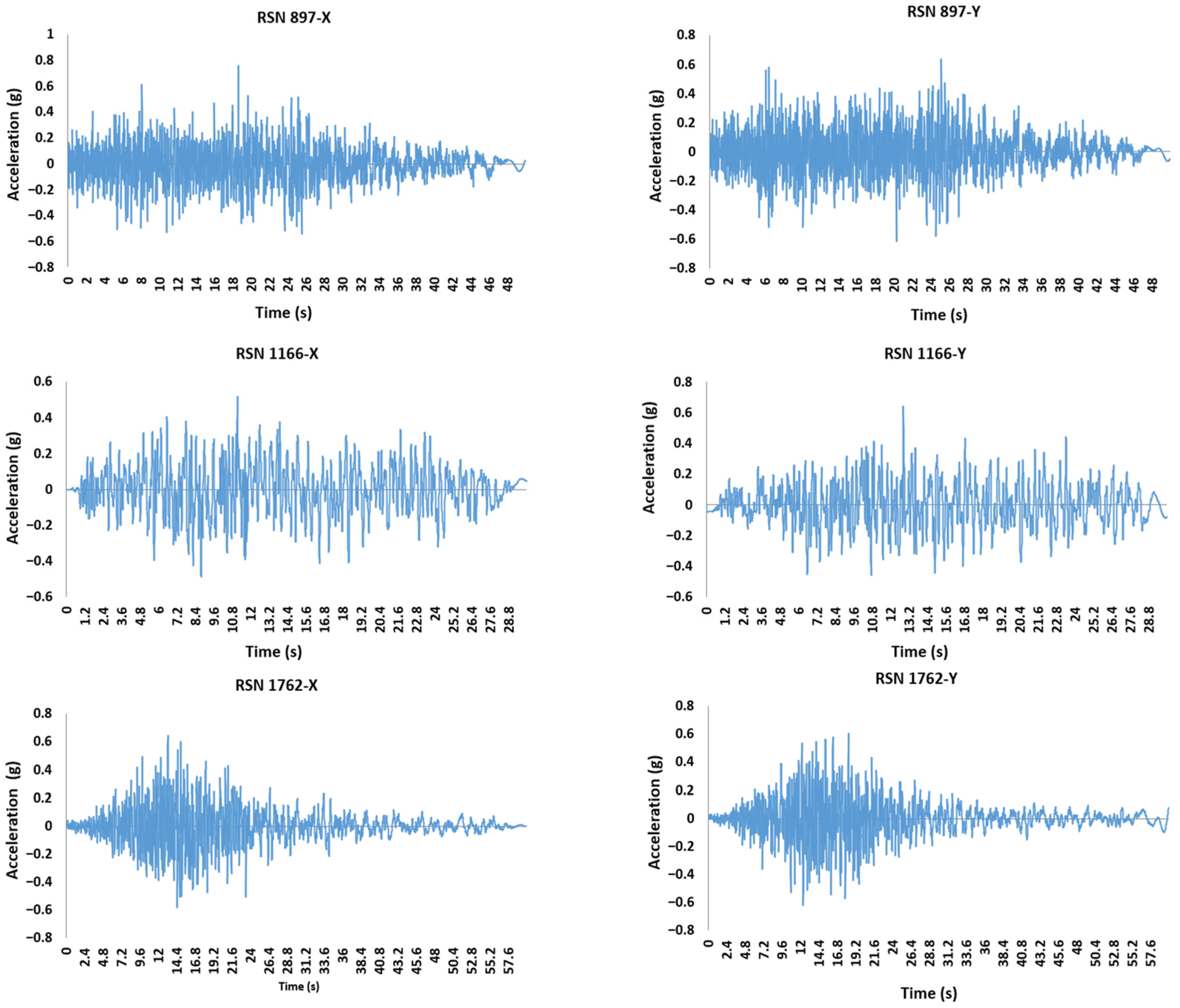
Nonlinear time history analyses were carried out by selecting strike-slip earthquake records; namely, RSN 897, RSN 1166, and RSN 1762 from the PEER NGA-West2 Ground Motion Database [28]. The two horizontal components of each earthquake record were applied simultaneously to the structure. Then, the earthquake loading was rotated by 90 degrees and applied again. The properties of the earthquake records are presented in Table 2. The selected ground motions were matched with the horizontal elastic design spectrum (Figure 3) in the X and Y directions. The matching of the selected earthquake records to the design spectrum was performed using the SeismoMatch 2025 software [29]. The matched records are presented in Figure 6.

2.5. Seismic Retrofitting of Building with CFRP Wrapping

In the second model of the building, CFRP wrapping was preferred for the columns. The reason for this preference was to increase the shear capacities of columns with 20 cm stirrup spacing. The shear capacity calculation of the column is presented below (Equations (5)–(8)).
V r = V c + V s
V c r = 0.65 f c t m b w d
V c = 0.8 V c r
V s = A s h f y w d d s
In the equations, V r is the shear capacity of the columns, V c r is the shear strength of the cross-section without confinement rebar (it is decreased by a coefficient of 0.8), and V s is the shear capacity due to confinement rebar. After the analysis of structure, as expected, the shear strength of columns was found to be lower than V e (shear demand calculated using capacity design method, V e / V r = 1.26). The beams were found to be safe against shear ( V e / V r < 1).
The properties of the CFRP are given in Table 3. The formulas provided in TBEC 2018 [22] were used for the properties of the CFRP used in the columns as follows (Equations (9)–(13)):
ρ f = 2 n f t f ( b + h ) b h
k a = 1 ( b 2 r ) 2 + ( h 2 r ) 2 3 b h
f l = k a ρ f ε f E f 2
ε f = min 0.004,0.5 ε f u
f c c = f c m 1 + 2.4 f l f c m
In the equations, ρ f is the volumetric ratio of CFRP, k a is the section efficiency coefficient, f l is the lateral confinement pressure, ε f is the strain of CFRP, f c c is the confined concrete strength, and f c m is the unconfined concrete strength.
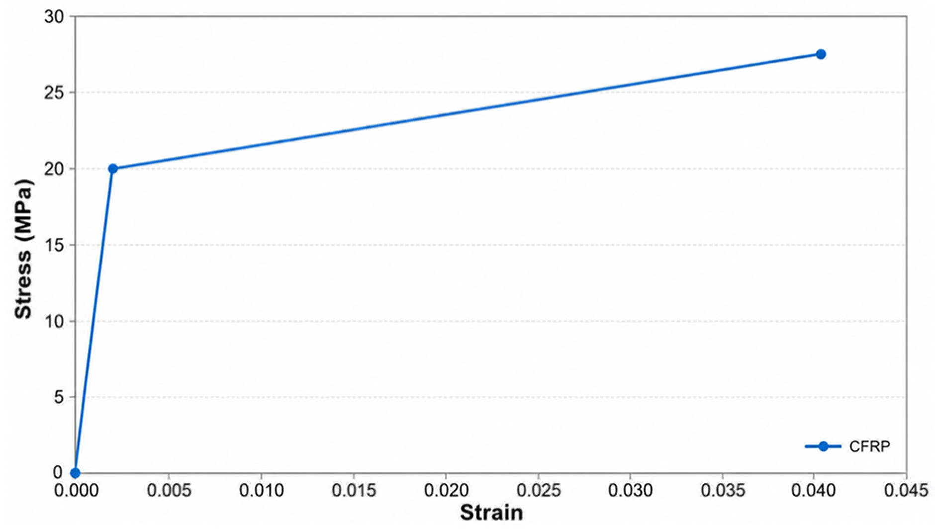
The columns were wrapped with carbon fiber-reinforced polymer in four layers. The material behavior of the CFRP-wrapped column is shown in Figure 7.

2.6. Seismic Retrofitting of Building with CFRP Wrapping and Idrizi Dampers

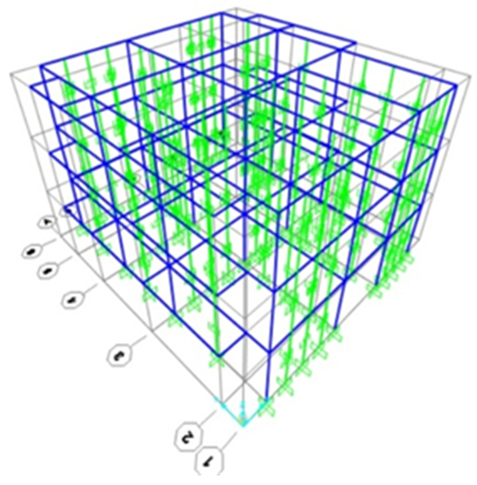
In the third model of building, the traditional infill walls were removed, and a wall system with lightweight concrete panels and Idrizi dampers was implemented in addition to CFRP wrapping of columns. Idrizi dampers were selected due to their low cost and innovative properties [9,10]. As explained in previous studies [9,10], Idrizi seismic dampers operate based on a friction-based energy dissipation mechanism activated by the relative lateral movement between the RC frame and the wall panel. Upon positioning the Idrizi devices between the wall panels and the beams, a vertical pre-compression force is induced across both components. Due to this compressive force, a controlled frictional contact surface that effectively dissipates incoming seismic energy is created. Experimental investigations under cyclic lateral loading [9,10] have demonstrated that these devices exhibit a stable and perfectly stiff and plastic hysteretic response across multiple cycles without any strength or stiffness degradation. The Idrizi dampers and the proposed innovative wall system possess unique mechanical performance and are based on the deformation capability of the structure. Unlike conventional friction or viscous dampers that require steel diagonals, the design of the Idrizi damper allows it to be directly embedded into lightweight concrete panels. Mechanically, the damper significantly reduces the dynamic demand on the main reinforced concrete frame by providing a highly stable, friction-based energy dissipation mechanism with excellent plastic hysteretic behavior. Furthermore, a polyurethane binder between panels and frame not only prevents shear deformation during seismic activity but also allows the wall panels to exhibit some resistance to vertical loads. As a result, brittle shear failure in the plastic hinge regions of the columns is prevented with CFRP wrap, and column ductility is increased, while the Idrizi dampers and the polyurethane-bonded panel system contribute to energy dissipation and the carrying of vertical loads. Here, lightweight concrete panels act as a separation element of rooms for architectural purposes; thus, an Idrizi damper was placed between the panel and the beam inside the frames where hollow brick walls were removed. In the X direction, 8 dampers per story were used, and in the Y direction, 7 dampers per story were used. Due to the proposed wall system, a 3.6 kN/m uniformly distributed load was applied to the beams.
As explained in Section 2.1, Section 2.2 and Section 2.3, due to the shear deformations of the polyurethane binder, the lateral force of the frame slightly increases; thus, two multi-linear plastic links with an effective stiffness of 2.67 kN/mm and a strength of 20 kN were again placed inside the frames that contain panels.
The Idrizi seismic damper is a frictional damper that operates in the in-plane loading direction inside the frame and was integrated into the structural model using the Plastic Wen link element [9,10]. It is characterized by an initial stiffness to control story drifts during minor seismic events, followed by a stable yielding phase at a force level that was calibrated to protect the RC frame and the lightweight concrete panels. Based on the hysteresis curves of dampers as explained in previous studies [9,10], the mechanical properties of the Idrizi damper are shown in Table 4.
In the out-of-plane direction of loading, the Idrizi damper does not resist loading, except for a very small frictional force. No information was found in past studies about this phenomenon [9,10]; thus, to represent the behavior, a small effective stiffness of 0.1 kN/mm was assumed. The model of a building with lightweight panels and dampers can be seen in Figure 8.

3. Results of Nonlinear Time History Analysis

Before performing nonlinear time history analysis, Sap2000 v26 was used to determine the eigenvalue–eigenvector solution and periods of the structures.
As summarized in Table 5, for both the non-retrofitted structure and the retrofitted structure with CFRP, the fundamental periods remained identical, which indicates that CFRP wrapping had a negligible contribution to the initial elastic stiffness. However, when hybrid retrofitting (CFRP and dampers) was implemented, a significant period elongation was observed in both directions. The period increased by 43% in the X direction (from 0.32 s to 0.46 s) and by 36% in the Y direction (from 0.39 s to 0.53 s). This happened because the innovative wall system with panels and dampers had no interaction with columns (Figure 1). The higher period along the X-axis physically demonstrated that the damper layout provided lower stiffness and higher drift compliance in this direction.
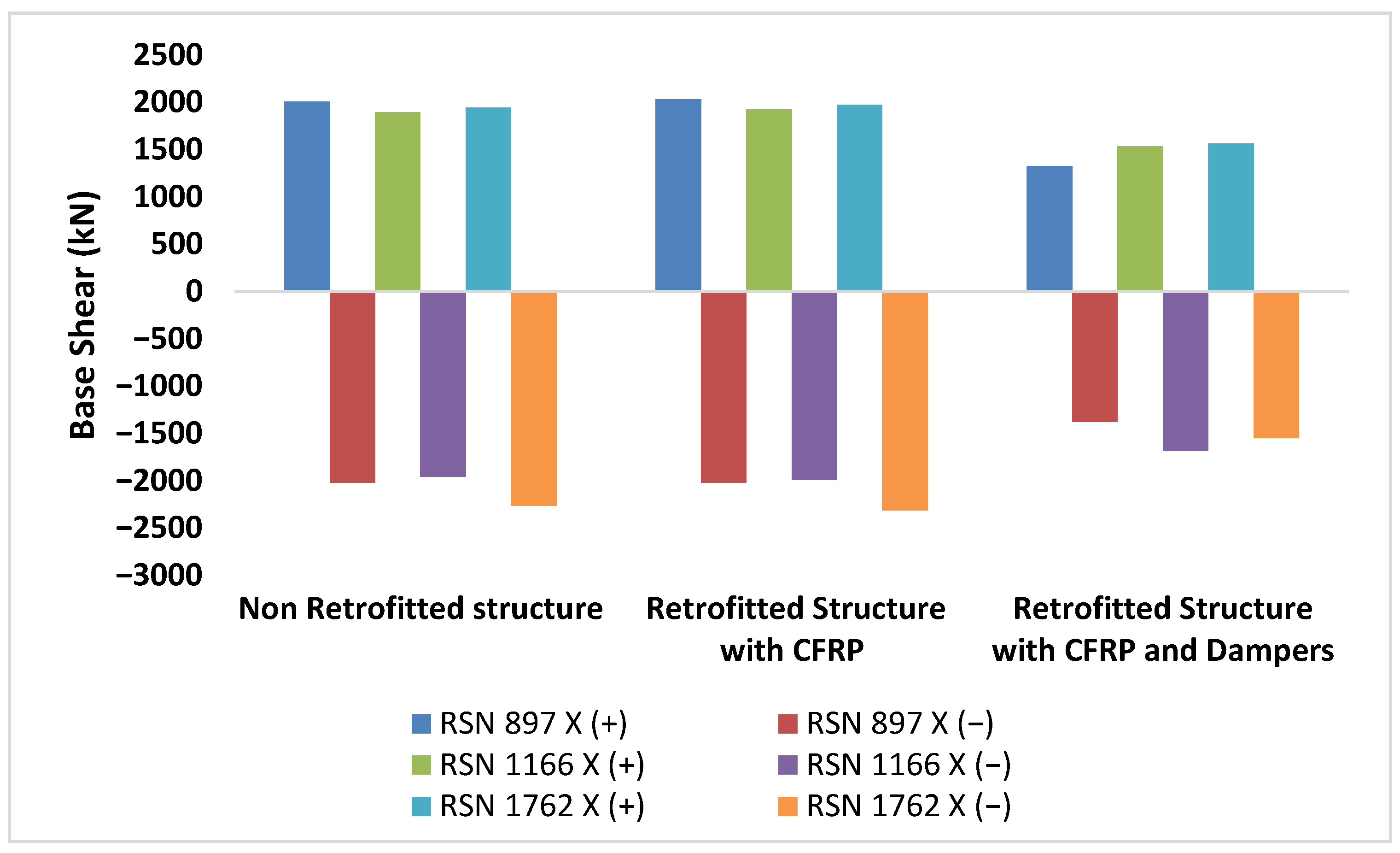
Following the nonlinear time history analysis, base shear forces, story displacements, and internal forces of structural members can be derived. First, it was noticed that when the hybrid retrofitting method was applied, the structure’s weight decreased from 5473.64 kN to 4773.16 kN (around a 12% decrease). In accordance with the TBEC-2018, the maximum response obtained from the analyses was considered in the performance evaluation. Therefore, in this study, the peak base shear, story displacement, and plastic hinge results were evaluated on a record-by-record basis, and the maximum response among the three spectrum-matched records was used for the main performance discussion. Since three ground motion records had been used in this particular study, the results could be considered as representative responses for the chosen records. The maximum base shear forces obtained from the nonlinear time history analysis for the retrofitted and non-retrofitted structures are presented in Figure 9 and Figure 10. In the figures, the letter X after the earthquake names indicates that the horizontal component in the X direction of the corresponding earthquake record was applied in the X direction of the structure. The letter Y indicates that the horizontal component in the Y direction of the corresponding earthquake record was applied in the X direction of the structure. The seismic demands were evaluated separately for the X and Y directions, considering both positive and negative response peaks across all earthquake records. In the X direction, the RSN 1762 record was identified as the most demanding seismic event, particularly in the negative direction. For the non-retrofitted structure, the peak base shear force was recorded as 2264.99 kN (RSN 1762 negative). When the columns were retrofitted with CFRP wrapping, this value slightly increased to 2315.35 kN. In contrast, the proposed wall system with CFRP and Idrizi seismic dampers provided a superior seismic response, reducing the peak base shear to 1551.009 kN. This corresponds to a significant reduction of 31% compared to the non-retrofitted case, highlighting the damper’s ability to dissipate energy. For the RSN 897 record, the base shear decreased from 2008.23 kN to 1328.87 kN for the non-retrofitted case and retrofitted case with the proposed wall system with dampers and CFRP. This indicates a 33% reduction.
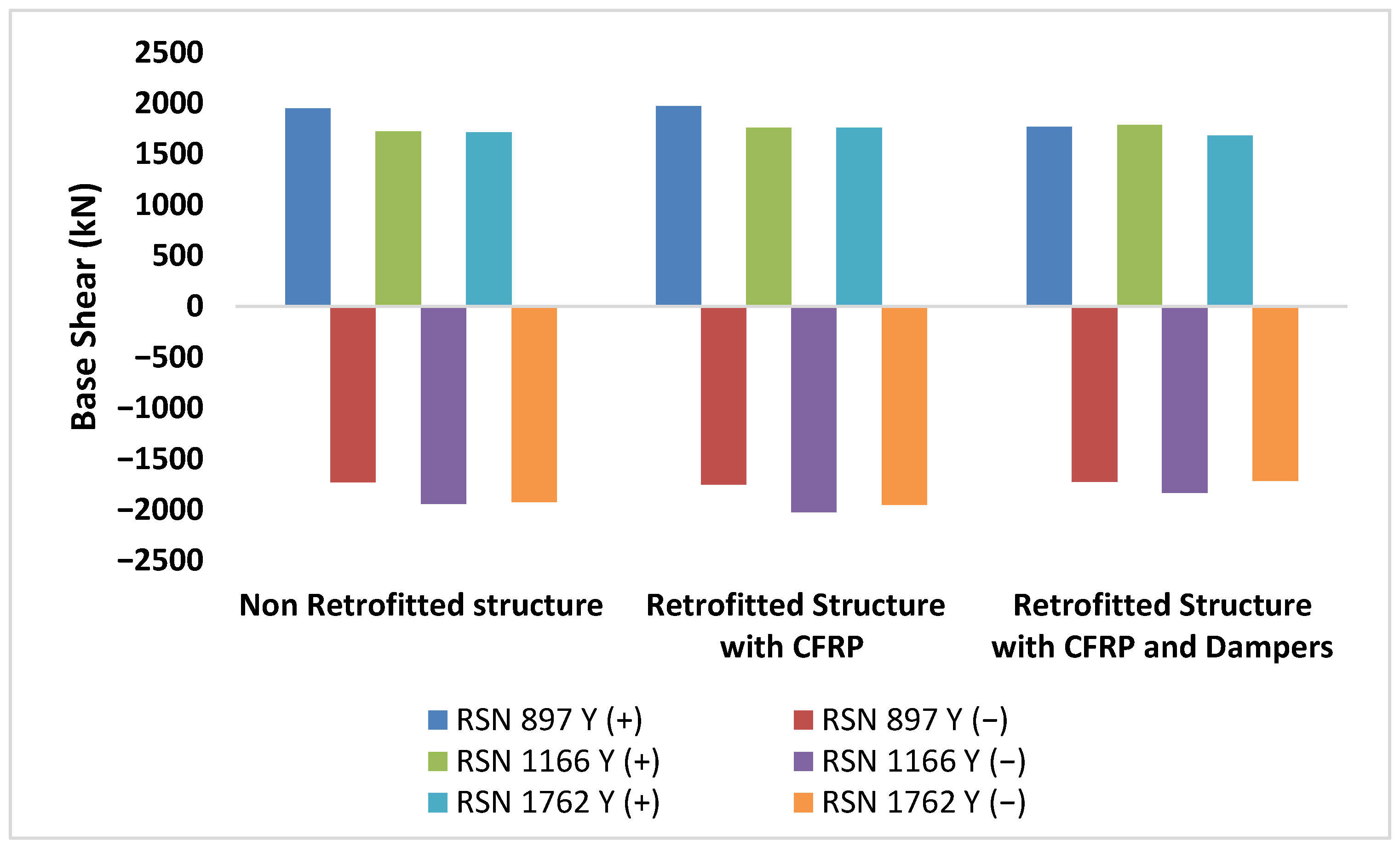
In the Y direction, the peak demand was governed by the RSN 897 record. The maximum base shear for the non-retrofitted structure was 1948.87 kN (positive direction). Similarly to the X direction, when the columns were retrofitted with CFRP, the base shear slightly increased, reaching 1975.42 kN. However, the implementation of the proposed wall system with CFRP and Idrizi dampers lowered the seismic demand to 1770.40 kN. This indicates a reduction of 9%. The same phenomenon was also observed for the other ground motions. For the RSN 1166 record, for the non-retrofitted case, the maximum force was 1942.84 kN. This value slightly increased to 2022.11 kN for the structure when CFRP wrapping was applied to columns. Hybrid retrofitting decreased the base shear to 1831 kN in the negative direction of the RSN 1166 record.
Significant directional discrepancy was observed in the peak base shear reductions. In the X direction, base shear reduction was around 31–33%, while in the Y direction, base shear reduction was around 6–9%. Following the installation of the hybrid retrofitting method, the fundamental period elongated by 43% in the X direction (from 0.32 s to 0.46 s) compared to 36% in the Y direction (from 0.39 s to 0.53 s). The higher period along the X-axis physically demonstrated that the damper layout provided lower stiffness and higher drift compliance in this direction. Under bidirectional time history excitations, the eccentricity of the non-retrofitted structure triggered significant torsional twisting. Furthermore, the torsional irregularity checks according to TBEC-2018 [22] based on the results obtained under the RSN 1762 earthquake record indicate that, in the existing structure, torsional irregularity exists (ηbi coefficient is bigger than 1.2) (Table 6 and Table 7). The structure’s period in torsional mode was 0.29 s. This value was close to periods in the X and Y directions (0.32–0.39 s). As presented in Table 5, the hybrid retrofitting method successfully introduced period elongation in the X and Y directions while the torsional period increased from 0.29 s to 0.36 s. Removal of infill walls and introduction of panels and dampers effectively suppressed the torsional modes of the structure. This pronounced flexibility along the X-axis allowed the parallel-aligned dampers to undergo larger strokes during the coupled torsional lateral responses. In Table 7, the results show that the hybrid retrofitting method effectively suppressed the structure’s torsional modes; thus, the dampers better dissipated the bi-directional dynamic forces. The significant directional discrepancy observed in the peak base shear reductions can be explained by this phenomenon.
The comparative analysis demonstrated that CFRP wrapping is essential for enhancing the local ductility and confinement of the columns. However, it does not change the stiffness of the structure; thus, base shear values slightly increased. Initial stiffness is not altered as CFRP wraps add almost no cross-sectional area. Yet, the confinement provided by CFRP results in enhanced ductility and resistance against early crushing of concrete. Consequently, plastic hinge redistribution becomes possible with absorption of more earthquake energy and an increased maximum base shear. Conversely, the Idrizi seismic dampers significantly decreased the global seismic demand on the retrofitted building across all considered earthquake records.
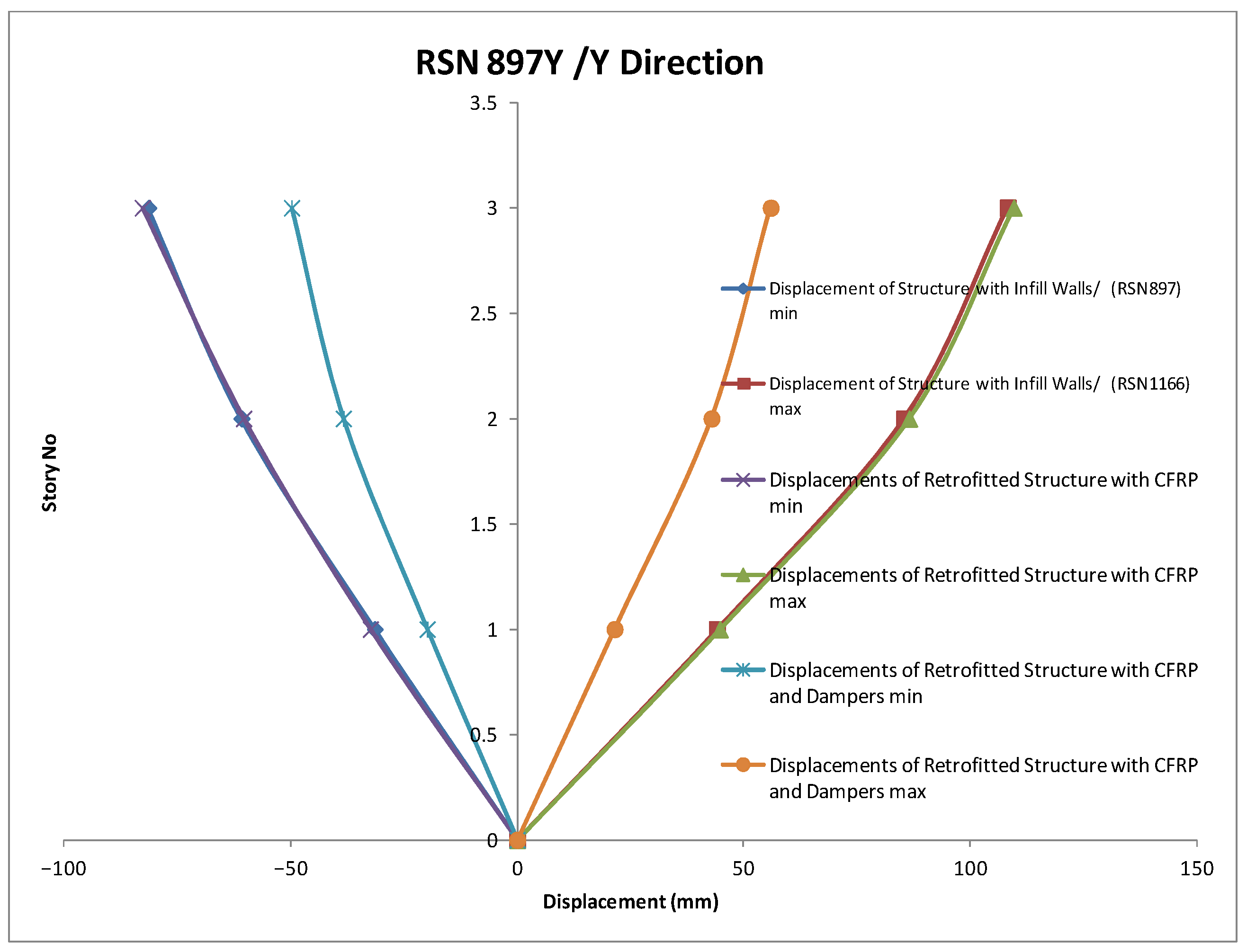
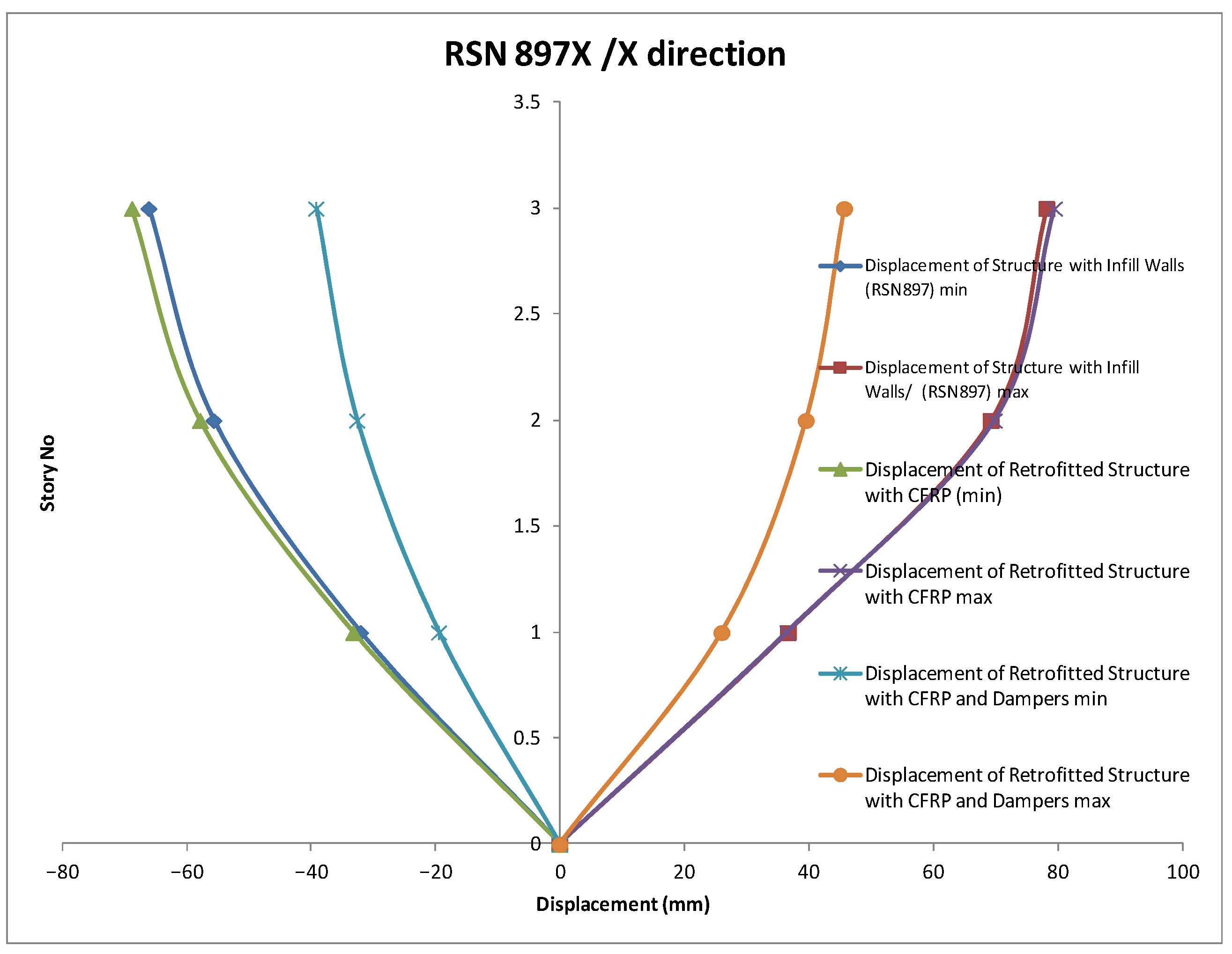
As shown in Figure 11 and Figure 12, the maximum story displacements for the top story were significantly reduced by the integration of seismic dampers when the RSN 897 record was applied as a loading. When the CFRP wrapping of columns was applied only, a slight increase in peak displacements occurred. The proposed wall system with CFRP and Idrizi dampers reduced the X direction (positive) displacement from 78.18 mm to 45.69 mm (41.56% reduction). A more pronounced performance was observed in the Y direction (positive), where the peak displacement was lowered by 48.32%, dropping from 108.24 mm to 55.94 mm for the non-retrofitted case and the retrofitted case by the proposed method. For the negative direction, a similar phenomenon was seen for the RSN 897 record.
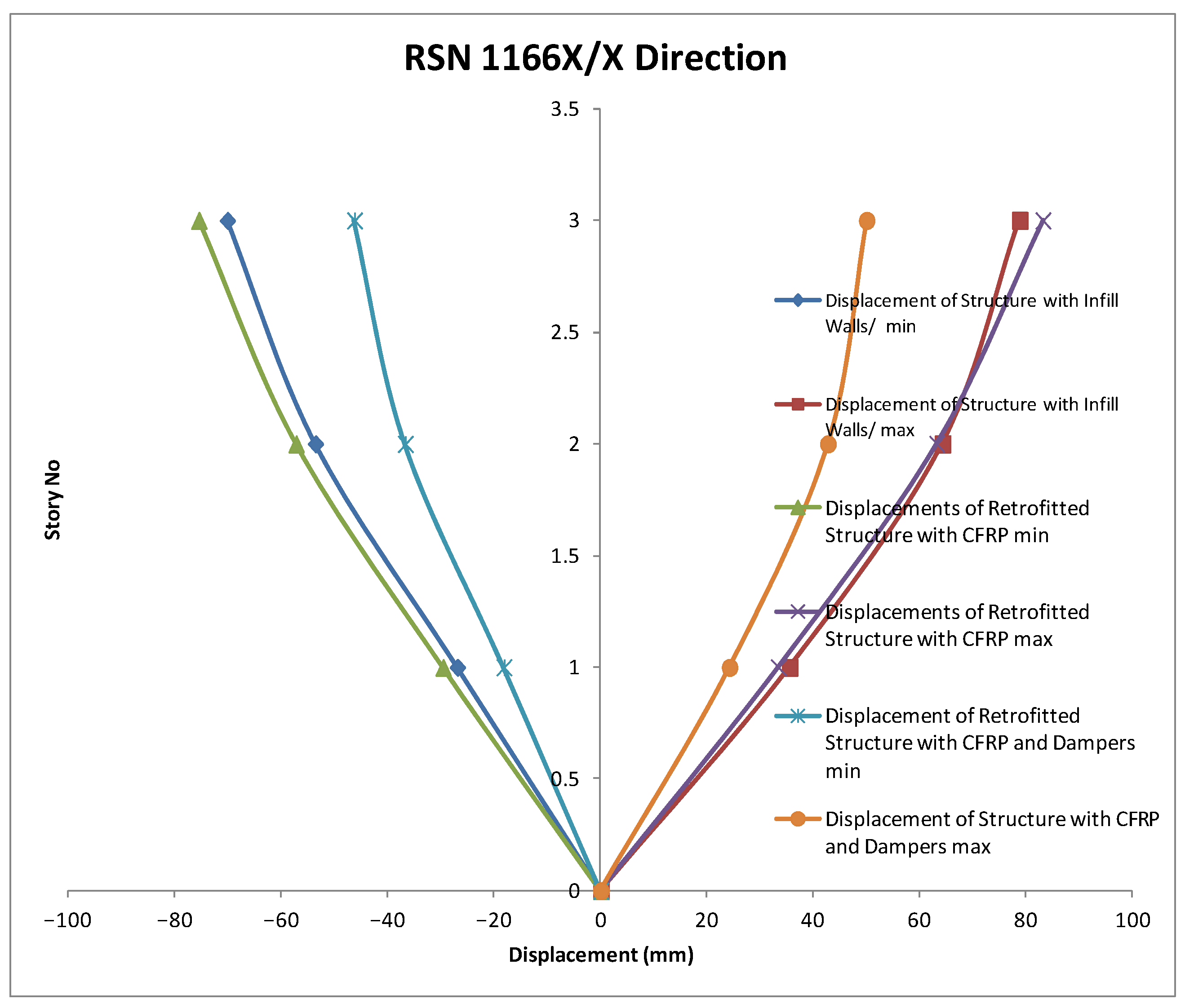
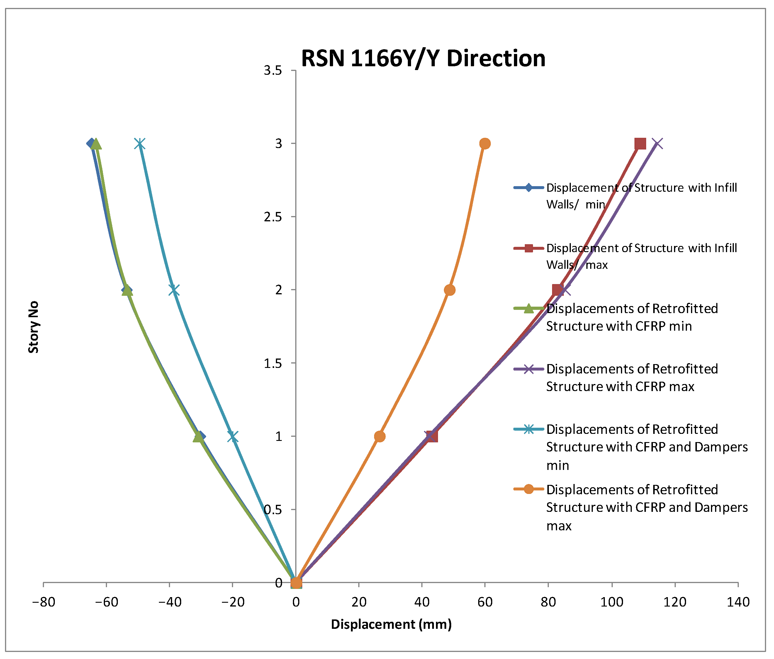
As shown in Figure 13 and Figure 14, analysis of story displacements under the RSN 1166 record further validates the efficiency of the proposed hybrid system. For the non-retrofitted structure, a maximum displacement of 108.95 mm occurs in the Y direction. Application of CFRP wrapping of columns led to a slight increase in displacement, reaching 114.33 mm (+4.94%), due to the modified stiffness characteristics. However, when the proposed wall system with CFRP and Idrizi dampers was applied, the peak displacement was reduced to 59.74 mm, marking a 45.17% reduction in the Y direction. Similarly, in the X direction, the proposed wall system lowered the demand from 78.69 mm (for the non-retrofitted case in the positive direction) to 49.92 mm (36.56% reduction). For the negative direction, a similar phenomenon was also observed.
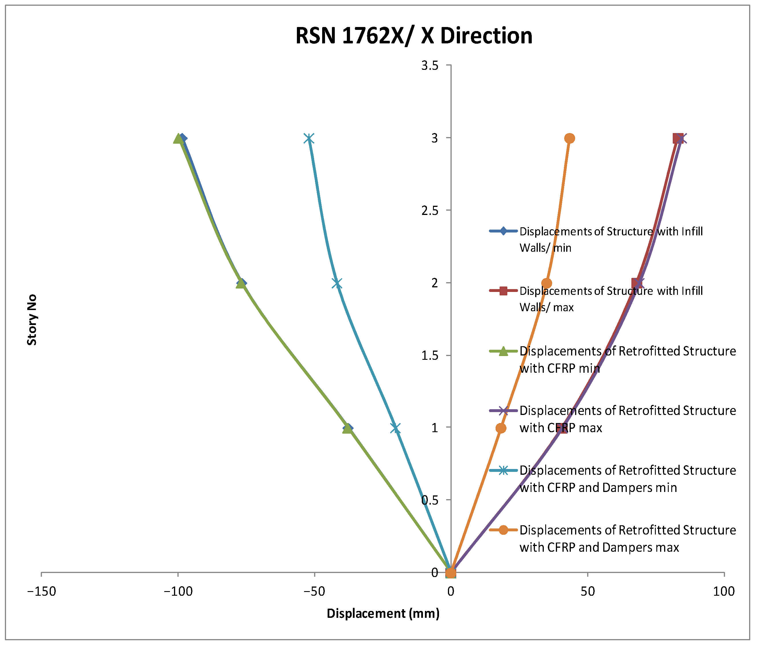
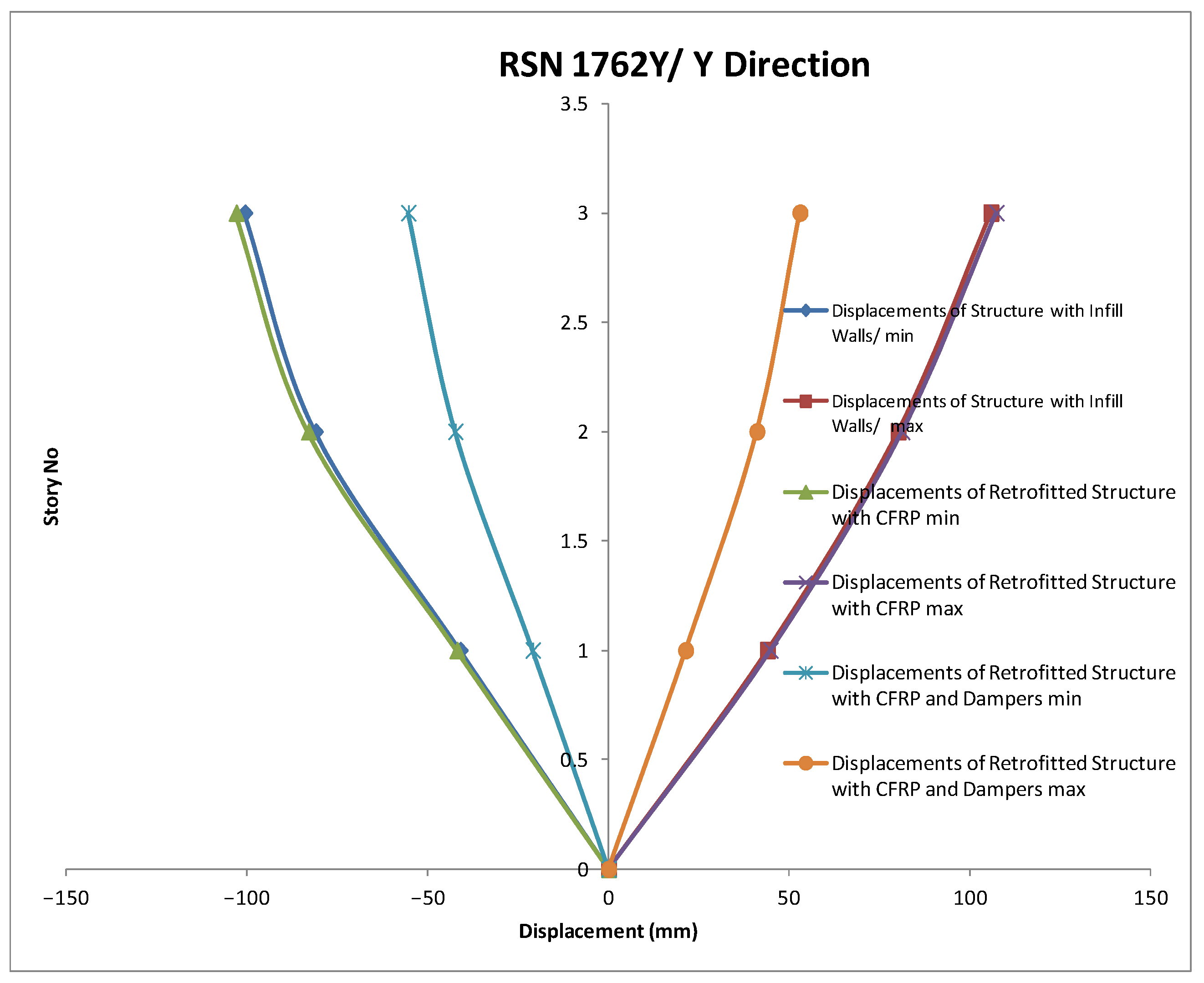
As shown in Figure 15 and Figure 16, the structural response under the RSN 1762 record, which imposed the highest displacement demands among the considered ground motions, further underscores the necessity of the proposed retrofit strategy.
For the non-retrofitted structure, the peak story displacement reached 105.79 mm in the Y direction (positive) and 98.38 mm in the X direction (negative). While the application of CFRP wrapping of columns resulted in minor increases in these peak values (to 107.31 mm and 99.72 mm, for the Y and X directions, respectively), the proposed wall system with CFRP and Idrizi dampers demonstrated control over the structural drift. The peak displacements were effectively reduced to 52.96 mm (50% reduction) in the Y direction (positive) and 51.96 mm (47.18% reduction) in the X direction (negative). These results confirm that the Idrizi dampers successfully limit the structural drift, thereby preventing excessive damage to the RC members and infill panels. The peak structural displacements when ground motion records were applied in orthogonal directions are presented in Table 8.
In the hybrid strengthening scheme with CFRP and dampers, it is observed that the peak displacements occurring in the orthogonal direction under earthquake action in the principal direction decreased significantly for all ground motion records. For example, for the X direction of the RSN1166 ground motion, a 34.47% reduction was achieved compared to the building with infilled walls. The highest reduction was observed in the X direction in the RSN897 ground motion record, with a decrease of 52.75%. The results can be seen in Table 6. A similar phenomenon was seen in previous studies where dampers were applied to enhance the seismic resilience of buildings. In one of these studies, it was stated that dampers reduced the roof displacement of hospital buildings by 60% [7]. In another study, it was observed that dampers reduced the inter-story drift ratios in buildings by 10–40% under frequent earthquakes and by 33–37% under the maximum considered earthquake [30].
Table 9 presents the plastic hinge results of the beams under the RSN897 earthquake record. Based on the results, it is seen that the hybrid strategy with CFRP and dampers reduced the hinges beyond the CP level by 72% compared to the infilled wall model. With the combined use of CFRP and dampers, 95.8% of the beam hinges reached the immediate occupancy (A to IO) performance level. Table 10 and Table 11 present the hinge values observed in the beams for the RSN 1166 and RSN 1762 earthquake records. In the hybrid model, a reduction was observed in the hinge values exceeding CP.

4. Limitations

Nonlinear time history analysis was conducted for three spectrum-matched records. Thus, the results obtained can be regarded as response characteristics of the considered structure for the chosen records but cannot be viewed as a statistical estimation of the structure’s seismic behavior.
Secondly, the analyses took into account only horizontal ground motion components. Near-fault pulse-type ground motion records and vertical ground motion components were not considered in this research.
Thirdly, the research is related to deterministic analysis of the structure’s seismic response characteristics like base shear, story displacement, and plastic hinge distribution. The fragility curves and probability of a structure’s collapse and probabilistic seismic demand modeling were not developed. Thus, the results should be treated as relative indicators of performance.
Finally, the model of the proposed Idrizi damper system was simulated using the Plastic Wen link elements based on the mechanical properties found in the existing literature [9,10]. While this method can be used to simulate the global hysteretic behavior of the dampers, there is no further validation of the damper model or the overall three-story retrofitted structure using any experiments in this research.

5. Conclusions

In this study, a building designed in accordance with the 1975 Turkish code, thus representing the problematic Turkish building stock, was modeled and examined under different earthquakes (Landers 1992, Kocaeli 1999, and Hector Mine 1999) through nonlinear time history analyses. The acceleration records of the ground motions were obtained and matched to the design spectrum. In the study, the building was modeled in three different ways: (i) with conventional infill walls, (ii) with the columns wrapped with CFRP together with infill walls, and (iii) with the columns wrapped with CFRP and Idrizi dampers added using a lightweight concrete panel instead of conventional infill walls.
Before the analysis of the building, the effect of the lightweight concrete panel—which interacts with the beam via the polyurethane binder—was analyzed in a single-story RC frame in Abaqus 2017. Although the primary purpose of the lightweight concrete panel was to allow the installation of the dampers, they provided a 18% increase in the lateral load capacity when compared with the RC frame without any walls. When compared with the conventional hollow clay brick infill wall (which increased the lateral load-carrying capacity by 41%) [20], the effect of the lightweight concrete panels was relatively small. Later, the panels were modeled in Sap2000 v26 for analysis of the building.
The primary findings obtained from the comparative analyses are summarized as follows.
  • Period Elongation and Torsional Isolation: The fundamental modal characteristics revealed that, while CFRP wrapping of columns introduced a negligible increment to the initial elastic stiffness, the hybrid retrofitting method (CFRP and dampers) increased the period of the structure in both directions and eliminated torsional irregularity. The fundamental period elongated by 43% in the X direction (from 0.32 s to 0.46 s) and by 36% in the Y direction (from 0.39 s to 0.53 s). The torsional period increased from 0.29 s to 0.36 s. The lightweight concrete panels had no interaction with columns and, thus, by increasing the structural periods, the hybrid retrofitting method effectively separated the lateral and torsional modes. This increment prevented the structure from experiencing uncontrolled, severe twisting during an earthquake caused by the distribution of conventional infill walls inside the structure.
  • Base Shear Forces and Displacements: The proposed hybrid retrofitting method reduced the seismic demand on the structure. It was observed that when the hybrid retrofitting method was applied, the base shear forces decreased in both the positive and negative directions compared to the hollow brick model (around 31–33% reduction in the X direction and 6–9% in the Y direction).
    Furthermore, it was observed that the displacements were decreased when the hybrid retrofitting method was applied. In the X direction, an average reduction of 41.13–42.70% was achieved, and in the Y direction, an average reduction of 32.74–46.89% was achieved for 90-degree rotated earthquake loadings.
  • Shear Failure of Columns: After analysis of the structure, as expected, the shear strength of columns was found to be lower than V e (shear demand calculated using capacity design method, V e / V r = 1.26). The hybrid retrofitting method increased the shear strength of columns due to CFRP wrapping.
  • Plastic Hinge Optimization: The plastic hinge performance of the beams across all selected ground motions highlighted the superior protective capacity of the hybrid retrofitting method. In the structure with conventional walls and in the structure with CFRP wrapping of columns, a critical portion of the beams suffered severe damage, with 13.9% to 18.4% of the hinges exceeding the collapse prevention limit state. However, when the hybrid retrofitting method (CFRP and dampers) was implemented, these heavy damage rates dramatically dropped to a range of only 4.2% to 6.0%. The proportion of beams remaining in the immediate occupancy performance level increased significantly to over 94% in all earthquake scenarios. This proves that the dampers effectively absorb the destructive seismic energy and prevent brittle failure mechanisms.
  • Practical Implications: From a practical engineering standpoint, the proposed hybrid retrofitting method offered a highly efficient and cost-effective solution for seismic retrofitting of existing problematic RC building stock. Conventional retrofitting methods that rely on the placement of additional RC shear walls are time-consuming, and residents must evacuate the structure. This hybrid method can be rapidly installed with minimal operational disruption. The use of lightweight concrete panels with polyurethane binder reduced the weight by 12% and eliminated the torsional irregularity. The use of Idrizi dampers reduced displacements and base shear forces and increased the energy dissipation in the structure.
Thus, the hybrid retrofitting method with CFRP wrapping and application of Idrizi dampers using lightweight concrete panels was found to be effective in practically strengthening the problematic RC building stock. The suggested method should be analyzed more in-depth in future studies with other parameters, such as vertical ground motion, near-fault ground motions, fragilities, and full-scale testing.

Author Contributions

Conceptualization, H.K. and A.N.; methodology, H.K. and A.N.; software, H.K. and A.N.; validation, H.K. and A.N.; formal analysis, A.N.; investigation, H.K. and A.N.; data curation, A.N.; writing—original draft preparation, H.K. and A.N.; writing—review and editing, H.K.; supervision, H.K. All authors have read and agreed to the published version of the manuscript.

Funding

This research received no external funding.

Data Availability Statement

Data is contained within the article.

Conflicts of Interest

The authors declare no conflicts of interest.

References

  1. Ilki, A.; Tore, E.; Demir, C.; Comert, M. Seismic Performance of a Full-Scale FRP Retrofitted Sub-standard RC Building. In Seismic Hazard and Risk Assessment; Springer: Cham, Switzerland, 2018; Volume 46, pp. 519–544. [Google Scholar] [CrossRef]
  2. Bensaid, C.; Tbatou, T. Numerical Studies on the Seismic Behavior of Reinforced Concrete Structures Strengthened with CFRP. J. Build. Pathol. Rehabil. 2024, 9, 148. [Google Scholar] [CrossRef]
  3. Amato, G.; Fossetti, M.; Cavaleri, L.; Papia, M. An Updated Model of Equivalent Diagonal Strut for Infill Panels. In Eurocode 8 Perspectives from the Italian Standpoint; Springer: Dordrecht, The Netherlands, 2009; pp. 119–128. [Google Scholar]
  4. Mainstone, R.J. On the Stiffness and Strengths of Infilled Frames. Proc. Inst. Civ. Eng. 1971, 4, 57–90. [Google Scholar]
  5. Akyildiz, A.T.; Kowalska-Koczwara, A.; Hojdys, Ł.; Krajewski, P. Change in Stiffness of Damaged RC Frame with Masonry Infills Connected with Stiff and Flexible Interfaces. In Brick and Block Masonry—From Historical to Sustainable Masonry; CRC Press: London, UK, 2020; pp. 546–552. [Google Scholar]
  6. Li, H.; Li, G.; Wang, S. Study and Application of Metallic Yielding Energy Dissipation Devices in Buildings. In Proceedings of the 10th National Conference on Earthquake Engineering, Anchorage, AK, USA, 21–25 July 2014; pp. 1–10. [Google Scholar]
  7. Arvind, R.; Santhi, M.H.; Malathi, G.; Bilgin, H. A Hybrid Comb Teeth-Friction Damper for Enhanced Seismic Resilience of RC Hospital Structures. Ing. Sismica 2025, 42, 20–37. [Google Scholar] [CrossRef]
  8. Nair, A.R.; Kale, R.C. Seismic Analysis of Multi-storey Structures: Comparing the Influence of Fluid Viscous Dampers and Shear Wall. Sādhanā 2026, 51, 35. [Google Scholar] [CrossRef]
  9. Idrizi, Z.; Idrizi, I. Idrizi Infill Wall System for Seismic Protection of Residential Buildings. J. Civ. Eng. Archit. 2017, 11, 862–869. [Google Scholar] [CrossRef][Green Version]
  10. Idrizi, Z.; Idrizi, I. An Innovative Seismic Protection System for Conventional RC Buildings. J. Civ. Eng. Archit. 2017, 11, 1077–1085. [Google Scholar] [CrossRef][Green Version]
  11. Koman, H. Improving the Behavior of RC Frames by Using Lightweight Concrete Panels and Metallic Elements. Kahramanmaraş Sütçü İmam Univ. J. Eng. Sci. 2024, 27, 105–120. [Google Scholar] [CrossRef]
  12. Dassault Systèmes SIMULIA. Abaqus: General-Purpose 3D Finite Element Analysis Software; Dassault Systèmes: Vélizy-Villacoublay, France, 2024. [Google Scholar]
  13. Koman, H.; Niğdelioğlu, A. Improving Seismic Performance of RC Structures Using AAC Blocks and Polyurethane Binder. Rev. Matéria 2025, 30, e20250513. [Google Scholar] [CrossRef]
  14. Zhai, C.; Kong, J.; Wang, X.; Chen, Z. Experimental and Finite Element Analytical Investigation of Seismic Behavior of Full-Scale Masonry Infilled RC Frames. J. Earthq. Eng. 2016, 20, 1171–1198. [Google Scholar] [CrossRef]
  15. Inculet, V. Nonlinear Analysis of Earthquake Induced Vibrations. Master’s Thesis, Aalborg University School of Engineering and Science, Aalborg, Denmark, 2016. [Google Scholar]
  16. Gao, J.; Sun, W.; Morino, K. Mechanical Properties of Steel Fiber-Reinforced High-Strength Lightweight Concrete. Cem. Concr. Compos. 1997, 19, 307–313. [Google Scholar] [CrossRef]
  17. Kwiecien, A. Highly Deformable Polymers for Repair and Strengthening of Cracked Masonry Structures. GSTF J. Eng. Technol. 2013, 2, 182–196. [Google Scholar] [CrossRef] [PubMed]
  18. Ksiel, P. Model Approach for Polymer Flexible Joints in Precast Elements Joints for Concrete Pavements. Master’s Thesis, Krakow University of Technology, Krakow, Poland, 2018. [Google Scholar]
  19. Viskovic, A.; Zuccarino, L.; Kwiecien, A. Quick Seismic Protection of Weak Masonry Infilling in Filled Frame Structures Using Flexible Joints. Key Eng. Mater. 2017, 747, 628–637. [Google Scholar] [CrossRef]
  20. Koman, H. A Proposal for Strengthening of RC Structures by Using High Strength Lightweight Concrete Panels and Polyurethane Binders. Erciyes Univ. J. Inst. Sci. Technol. 2023, 39, 521–537. Available online: https://izlik.org/JA52XA49UM (accessed on 12 July 2026).
  21. Sarı, H. Mevcut Betonarme Yapılardaki Tasarım Olumsuzluklarının Yapı Performansına Etkisi. Master’s Thesis, Sakarya University, Sakarya, Türkiye, 2010. [Google Scholar]
  22. AFAD. Turkish Building Earthquake Code (TBEC 2018); Disaster and Emergency Management Presidency: Ankara, Türkiye, 2018. [Google Scholar]
  23. Cogurcu, M.T. Construction and Design Defects in the Residential Buildings and Observed Earthquake Damage Types in Turkey. Nat. Hazards Earth Syst. Sci. 2015, 15, 931–945. [Google Scholar] [CrossRef]
  24. Computers and Structures Inc. Sap2000: Integrated Software for Structural Analysis and Design; Computers and Structures Inc.: Berkeley, CA, USA.
  25. Cavaleri, L.; Di Trapani, F. Cyclic Response of Masonry Infilled RC Frames: Experimental Results and Simplified Modeling. Soil Dyn. Earthq. Eng. 2014, 65, 224–242. [Google Scholar] [CrossRef]
  26. Mahmud, E.; Bonev, Z.; Abdulahad, E. Nonlinear Seismic Analysis of Masonry Infilled RC Frame Structures. Građevinski Mater. I Konstr. 2019, 62, 17–25. [Google Scholar] [CrossRef]
  27. Koman, H.; Nohutcu, H.; Kılıç, G.; Kwiecien, A.; Ercan, E. Improving the Seismic Behaviour of RC Frames with Mortarless Blocks. Građevinar 2025, 77, 219–236. [Google Scholar] [CrossRef]
  28. Ancheta, T.D.; Darragh, R.B.; Stewart, J.P.; Seyhan, E.; Silva, W.J.; Chiou, B.S.; Wooddell, K.; Graves, R.W.; Kottke, A.; Boore, D.M.; et al. PEER NGA-West2 Database; Pacific Earthquake Engineering Research Center: Berkeley, CA, USA, 2013; Volume 172. [Google Scholar]
  29. Seismosoft. SeismoMatch: A Computer Program for Spectrum Matching of Earthquake Records; Seismosoft Ltd.: Pavia, Italy, 2025. [Google Scholar]
  30. Ma, P.; Yuan, S. Seismic Retrofitting of RC Frames Using Viscous Dampers: Numerical Simulation and Nonlinear Response Analysis. Infrastructures 2025, 10, 235. [Google Scholar] [CrossRef]
Figure 1. The RC frame and lightweight concrete panel in Abaqus.
Buildings 16 02825 g001
Figure 2. Load capacities of RC frames with panels in Abaqus 2017 and Sap2000 v26.
Buildings 16 02825 g002
Figure 3. Horizontal elastic design spectrum.
Buildings 16 02825 g003
Figure 4. Plan of normal story in Sap2000 v26.
Buildings 16 02825 g004
Figure 5. Building with hollow brick infill walls.
Buildings 16 02825 g005
Figure 6. The records of RSN897, RSN1166, and RSN1762 matched to the design spectrum.
Buildings 16 02825 g006
Figure 7. Behavior of CFRP-wrapped concrete.
Buildings 16 02825 g007
Figure 8. Building with lightweight concrete panels and dampers.
Buildings 16 02825 g008
Figure 9. Base shear forces in X direction.
Buildings 16 02825 g009
Figure 10. Base shear forces in Y direction.
Buildings 16 02825 g010
Figure 11. Displacement of structures in X direction (RSN 897 record).
Buildings 16 02825 g011
Figure 12. Displacement of structures in Y direction (RSN 897 record).
Buildings 16 02825 g012
Figure 13. Displacement of structures in X direction (RSN 1166 record).
Buildings 16 02825 g013
Figure 14. Displacement of structures in Y direction (RSN 1166 record).
Buildings 16 02825 g014
Figure 15. Displacement of structures in X direction (RSN 1762 record).
Buildings 16 02825 g015
Figure 16. Displacement of structures in Y direction (RSN 1762 record).
Buildings 16 02825 g016
Table 1. The force displacement relationships of the link that represents traditional infill between axis B and axis C.
Displacement (mm)Force (kN)
−30−10
−26.52−38.75
−4.62−56.25
−1.436−42.187
00
13
Table 2. Properties of selected ground motions.
NGA RSNMagnitudeRjb (km)Rrup (km)Vs30 (m/s)
897
(Landers 1992)
7.2841.4341.43635.01
1166
(Kocaeli 1999)
7.5130.7330.73476.62
1762
(Hector Mine 1999)
7.1341.8143.05382.93
Table 3. The technical properties of the carbon fiber-reinforced polymer.
PropertyValue
ProductDOWAKSA UDS600
Tensile Strength4900 MPa
Elongation at Break2.00%
Elastic Modulus245,000 MPa
Weight600 g/m2
Equivalent Thickness0.337 mm
Width500 mm
Cross-Sectional Area168.5 mm2
Application Temperature+5 °C to +25 °C
Table 4. The mechanical properties of Idrizi damper in the in-plane direction of loading.
Eff. Stiff.:4 kN/mm
Yield:28 kN
Yield Disp.:7 mm
Max S.:33 kN
Post Yield Ratio:0.038
Yield. Exp.:1
Table 5. Periods of structures.
Structural ConfigurationPeriod in X Direction [s]Period in Y Direction [s]
Non-Retrofitted (Bare) Structure0.320.39
Retrofitted Structure with CFRP0.320.39
Retrofitted Structure with CFRP and Dampers0.460.53
Table 6. Torsional irregularity (A1) check of the existing building based on the results of the RSN 1762 earthquake.
StoryDirectionEnvelopeΔi, min (mm)Δi, max (mm)Δi, avg (mm)ηbiA1 İrregularity
1XMaximum39.45644.68742.0711.062No
1XMinimum36.72147.05841.8891.123No
1YMaximum31.19343.95337.5731.170No
1YMinimum31.50441.03136.2671.131No
2XMaximum25.98137.75131.8661.185No
2XMinimum32.93041.85037.3901.119No
2YMaximum28.60037.91233.2561.140No
2YMinimum28.27142.38435.3271.200No
3XMaximum11.93719.81515.8761.248Yes
3XMinimum17.17024.38420.7771.174No
3YMaximum19.75327.15823.4551.158No
3YMinimum13.52620.75617.1411.211Yes
Table 7. Torsional irregularity (A1) check of the structure with the hybrid method based on the results of the RSN 1762 earthquake.
StoryDirectionEnvelopeΔi, min (mm)Δi, max
(mm)
Δi, avg (mm)ηbiA1 Irregularity
1XMaximum17.38123.81120.5961.156No
1XMinimum19.18923.45621.3221.100No
1YMaximum20.27521.32820.8011.025No
1YMinimum18.39320.97619.6841.066No
2XMaximum15.21119.49817.3551.124No
2XMinimum15.81922.64919.2341.178No
2YMaximum18.1619.98319.0711.048No
2YMinimum18.8721.5920.231.067No
3XMaximum7.2398.4497.8441.077No
3XMinimum8.34711.3119.8291.151No
3YMaximum10.54613.5412.0431.124No
3YMinimum11.7113.13212.4211.057No
Table 8. Peak structural displacements in orthogonal directions under ground motion (mm).
Earthquake RecordsEarthquake
Direction
StoryWith Infilled WallWith CFRPWith CFRP + Dampers
MinMaxMinMaxMinMax
RSN 897X1−28.0635.21−26.7537.08−17.8019.29
2−54.3765.45−53.3066.65−37.9736.38
3−69.7998.93−72.8998.38−48.8346.74
Y1−31.5828.72−31.7028.57−17.2619.39
2−59.5254.23−60.5152.27−38.5437.02
3−75.7166.06−77.8264.21−50.1445.77
RSN 1166X1−36.6235.18−35.7336.22−22.8920.99
2−65.2265.80−65.4867.64−44.6338.79
3−79.4381.78−79.3884.92−58.6654.27
Y1−34.1834.01−34.9734.03−20.9321.39
2−63.5460.56−64.3562.01−42.1837.42
3−83.3171.80−84.8173.44−54.4650.02
RSN 1762X1−39.7938.79−40.6038.35−25.0423.85
2−74.9064.88−74.8865.55−48.3145.61
3−92.8388.98−93.3592.00−62.1157.20
Y1−35.3033.79−35.4234.23−24.9918.63
2−66.4961.44−66.7562.40−45.8937.35
3−82.9274.08−83.1875.53−56.5646.38
Table 9. Hinge results of beams under RSN897 (Max.).
Element TypePerformance LevelWith Infilled WallWith CFRPWith CFRP + Dampers
NumberRatioNumberRatioNumberRatio
BeamsA–IO155%86.1144%82.8161%95.8
IO–LS0%0.01%0.60%0.0
LS–CP0%0.00%0.00%0.0
>CP25%13.929%16.77%4.2
Table 10. Hinge results of beams under RSN1166 (Max.).
Element TypePerformance LevelWith Infilled WallWith CFRPWith CFRP + Dampers
NumberRatioNumberRatioNumberRatio
BeamsA–IO154%85.6147%84.5158%94.0
IO–LS0%0.00%0.00%0.0
LS–CP0%0.01%0.60%0.0
>CP26%14.426%14.910%6.0
Table 11. Hinge results of beams under RSN1762 (Max.).
Element TypePerformance LevelWith Infilled WallWith CFRPWith CFRP + Dampers
NumberRatioNumberRatioNumberRatio
BeamsA–IO152%84.4142%81.6159%94.6
IO–LS0%0.00%0.00%0.0
LS–CP0%0.00%0.01%0.6
>CP28%15.632%18.48%4.8
Disclaimer/Publisher’s Note: The statements, opinions and data contained in all publications are solely those of the individual author(s) and contributor(s) and not of MDPI and/or the editor(s). MDPI and/or the editor(s) disclaim responsibility for any injury to people or property resulting from any ideas, methods, instructions or products referred to in the content.