
Vibration Performances of a Full-Scale Assembled Integral Two-Way Multi-Ribbed Composite Floor

Abstract
1. Introduction
2. Experimental Investigation
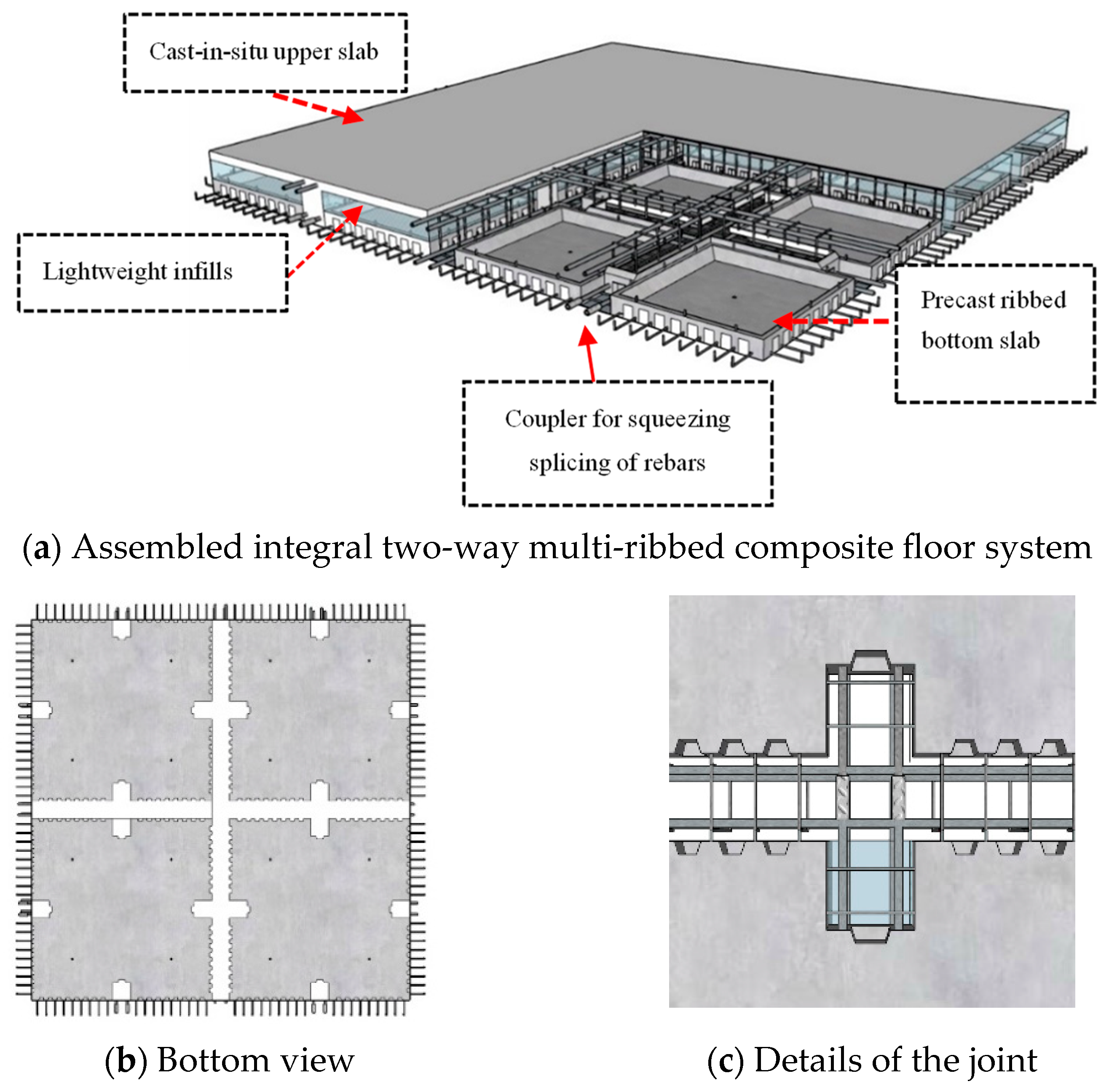
2.1. Introduction of the Innovative Floor System
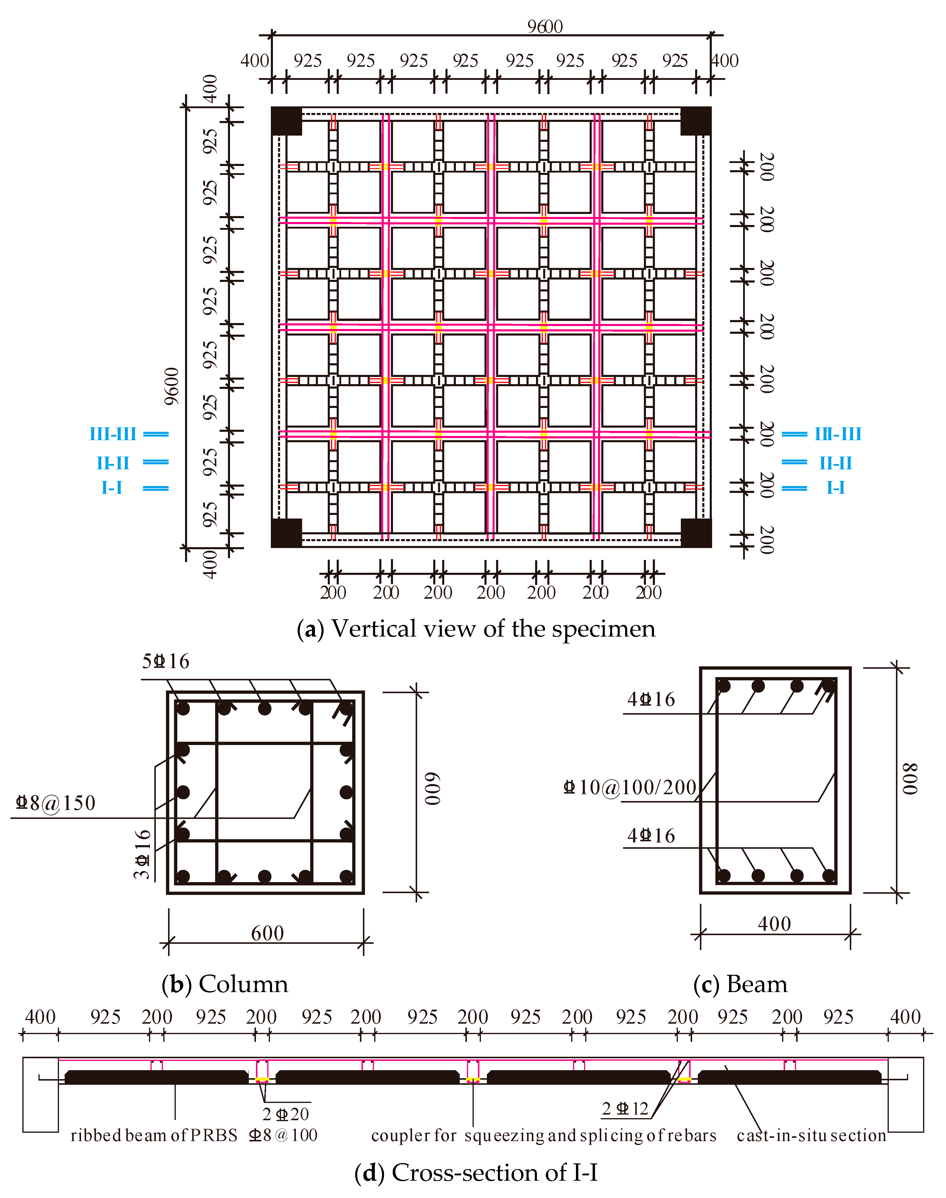
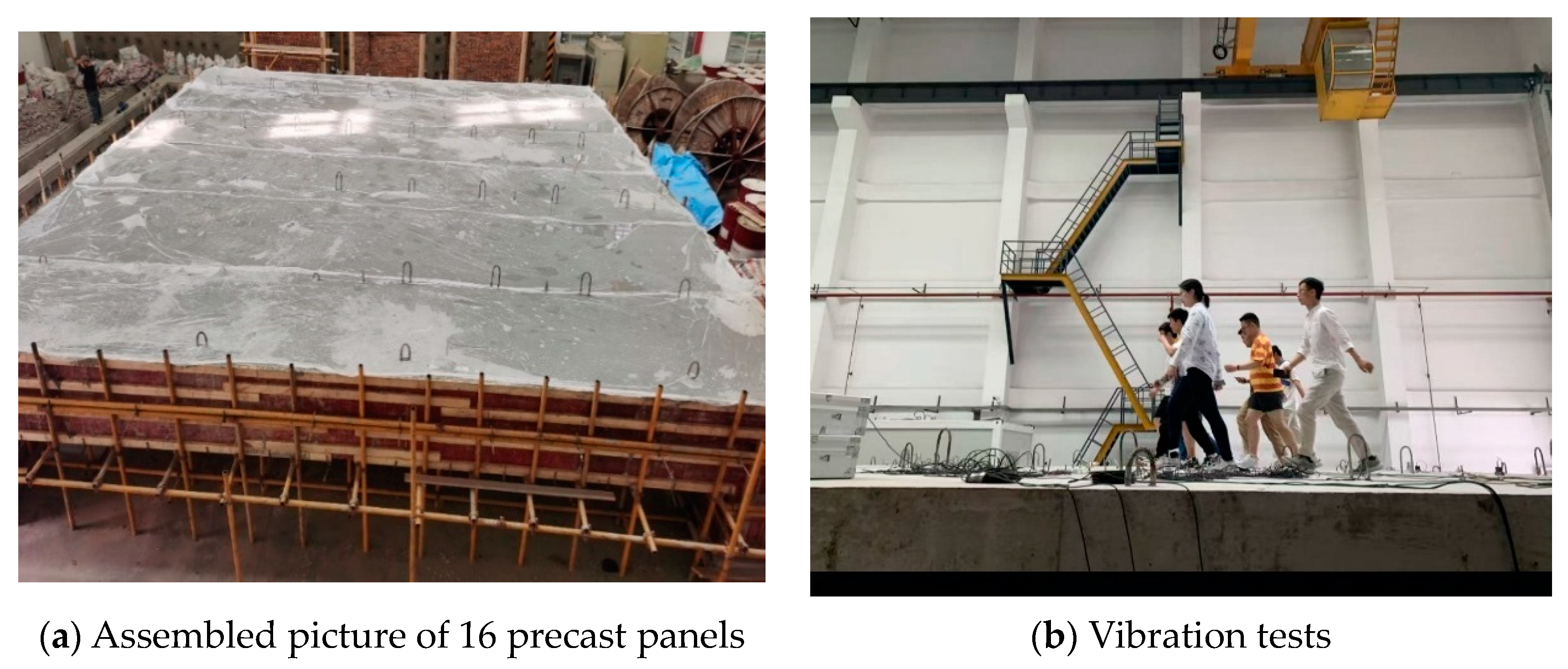
2.2. Specimen Preparation
2.3. Material Properties
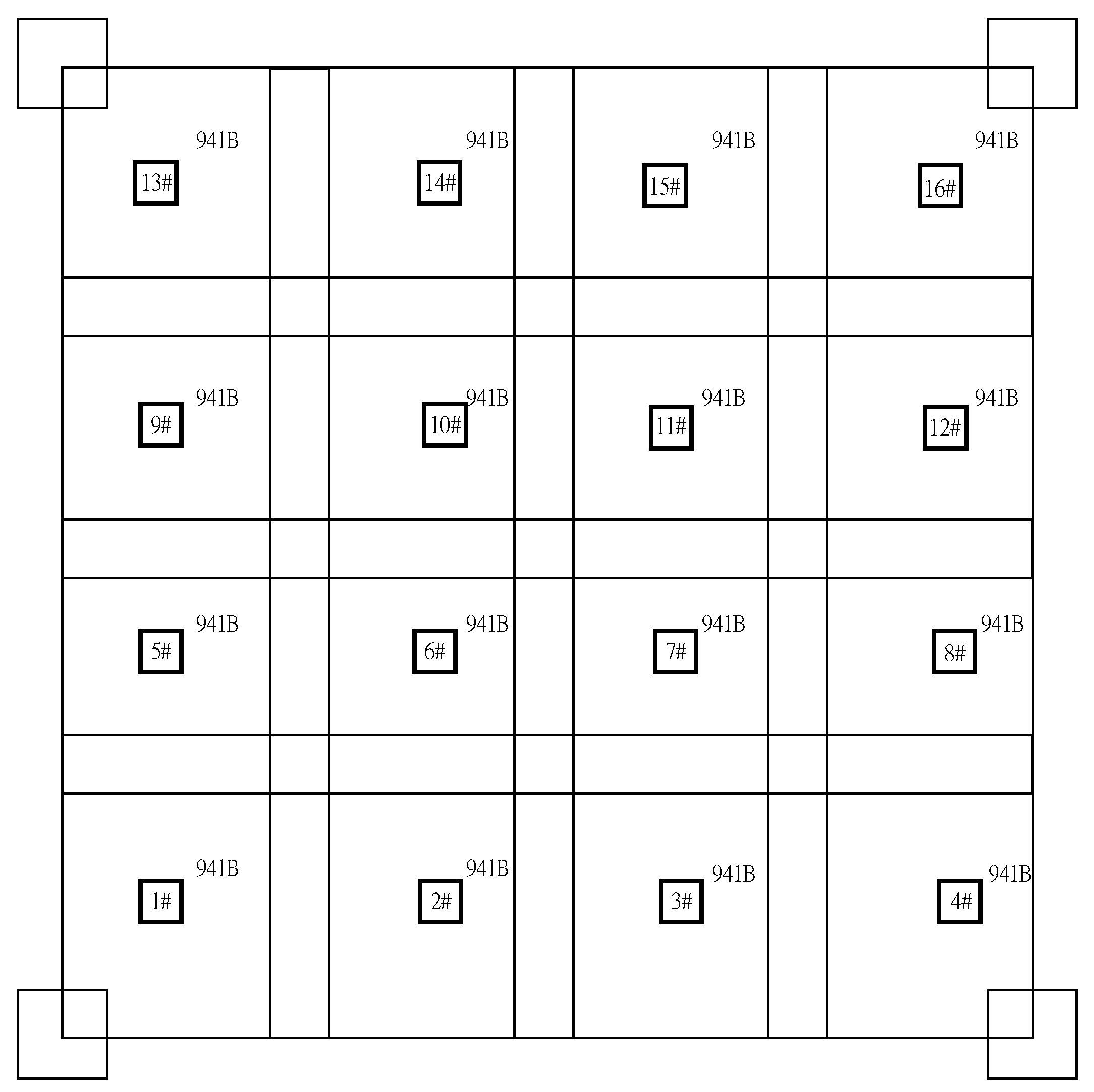
2.4. Test Method and Sensor Distribution
3. Experimental Results
3.1. Vibration Modes, Frequencies, and Damping Ratios
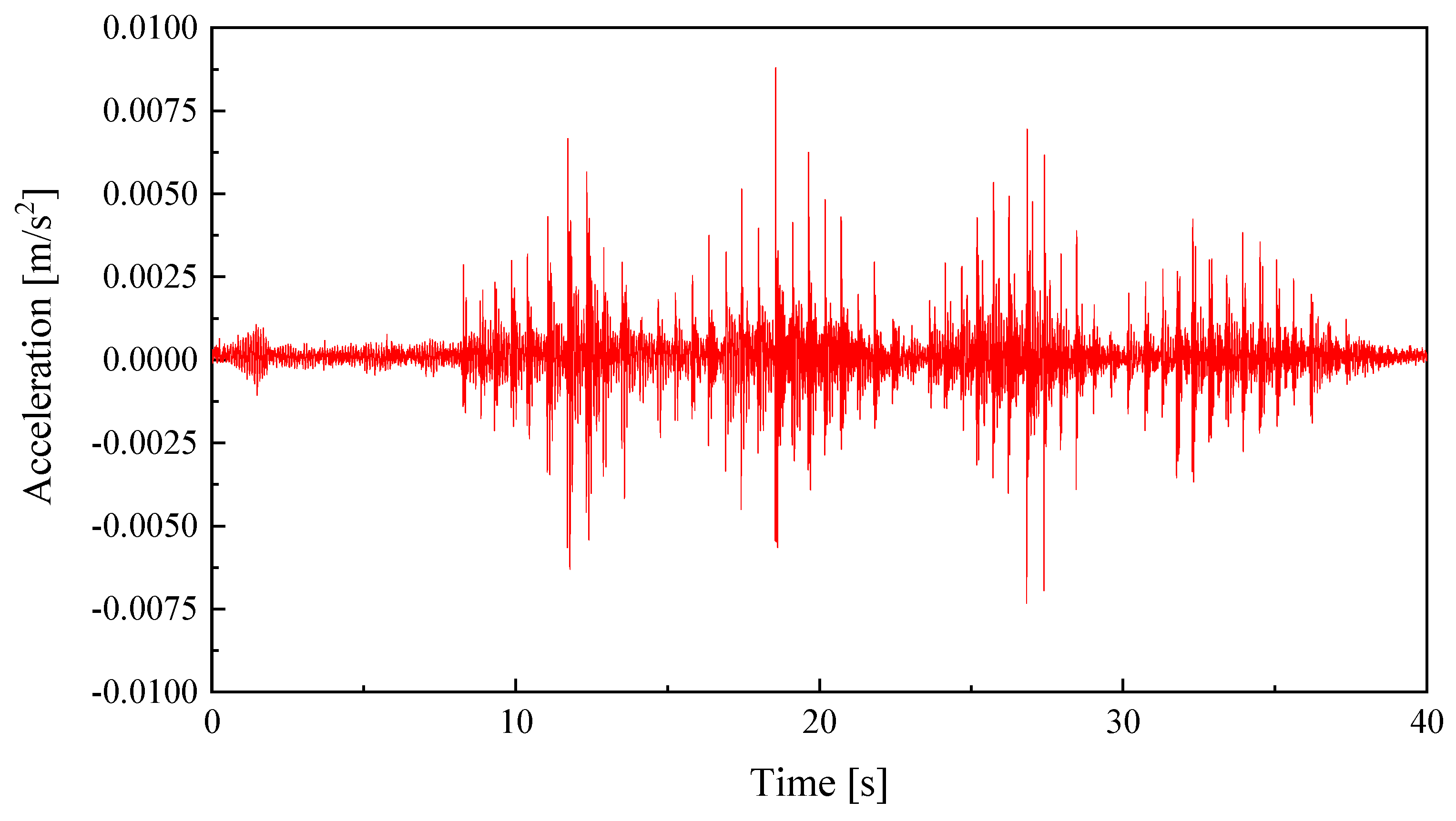
3.2. Acceleration Response of the Single-Person Tests
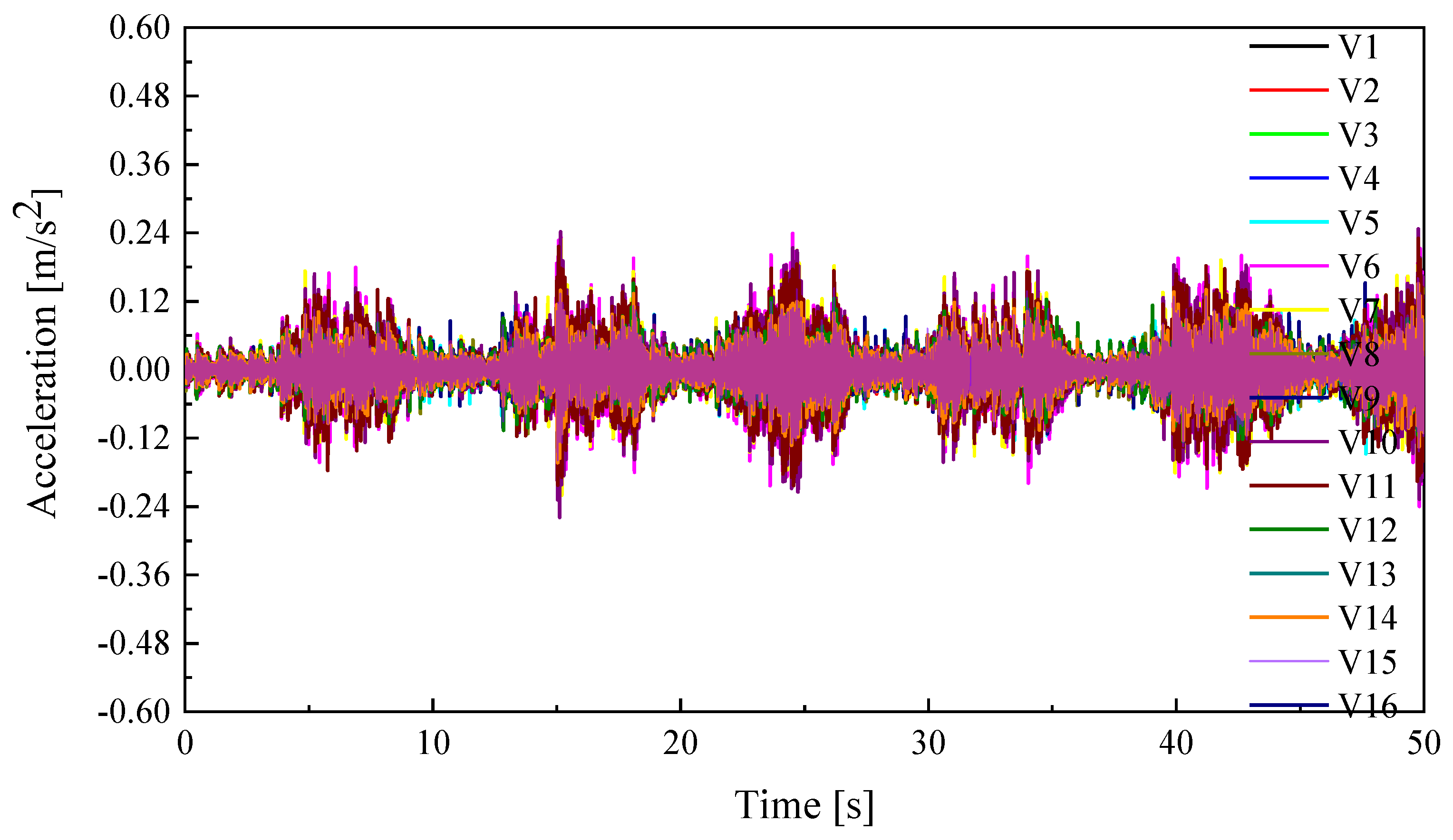
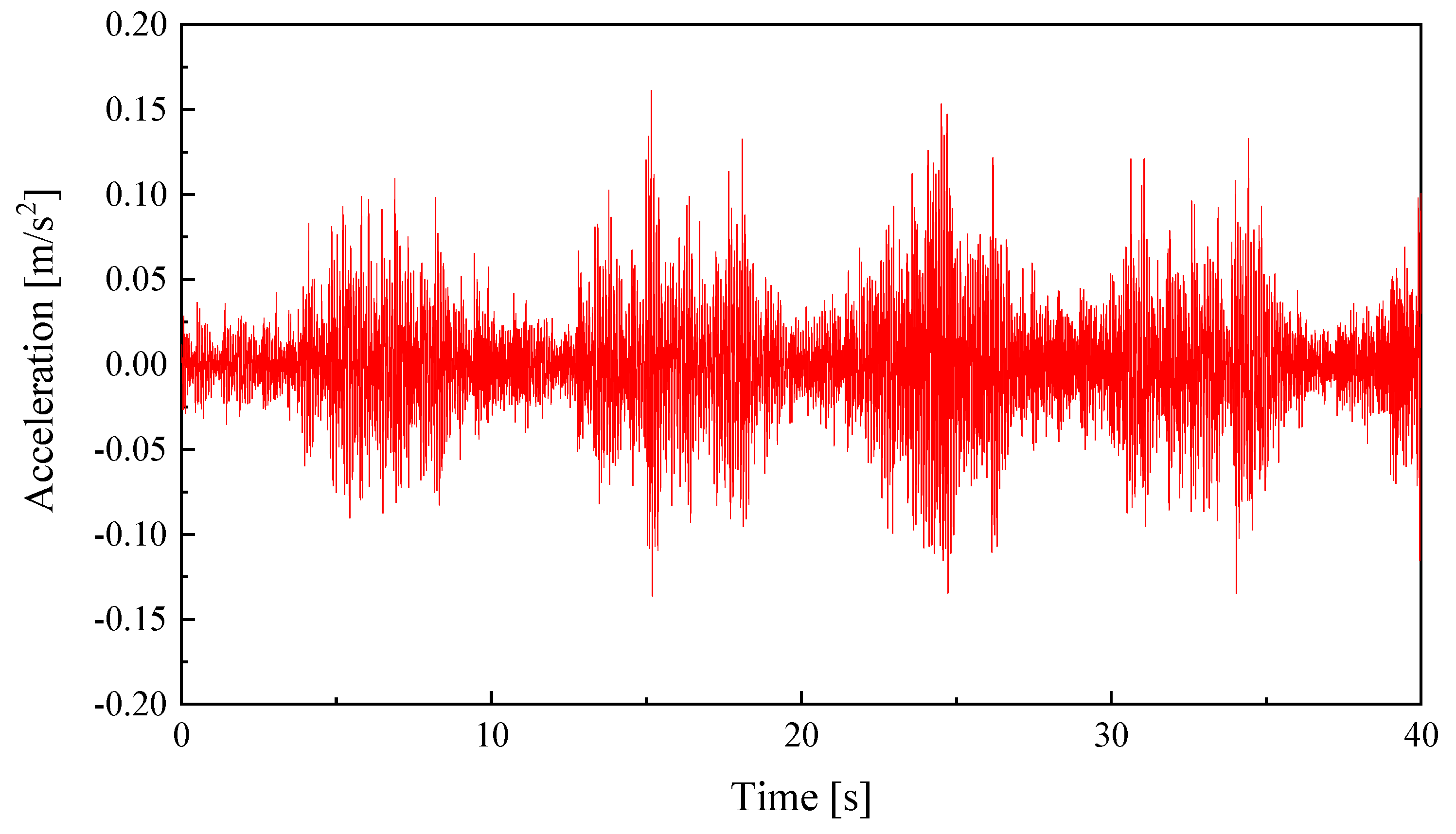
3.3. Acceleration Response of the Multi-Person Tests
4. Theoretical Derivation
4.1. Simplification of Beam–Plate Connection and Boundary Conditions
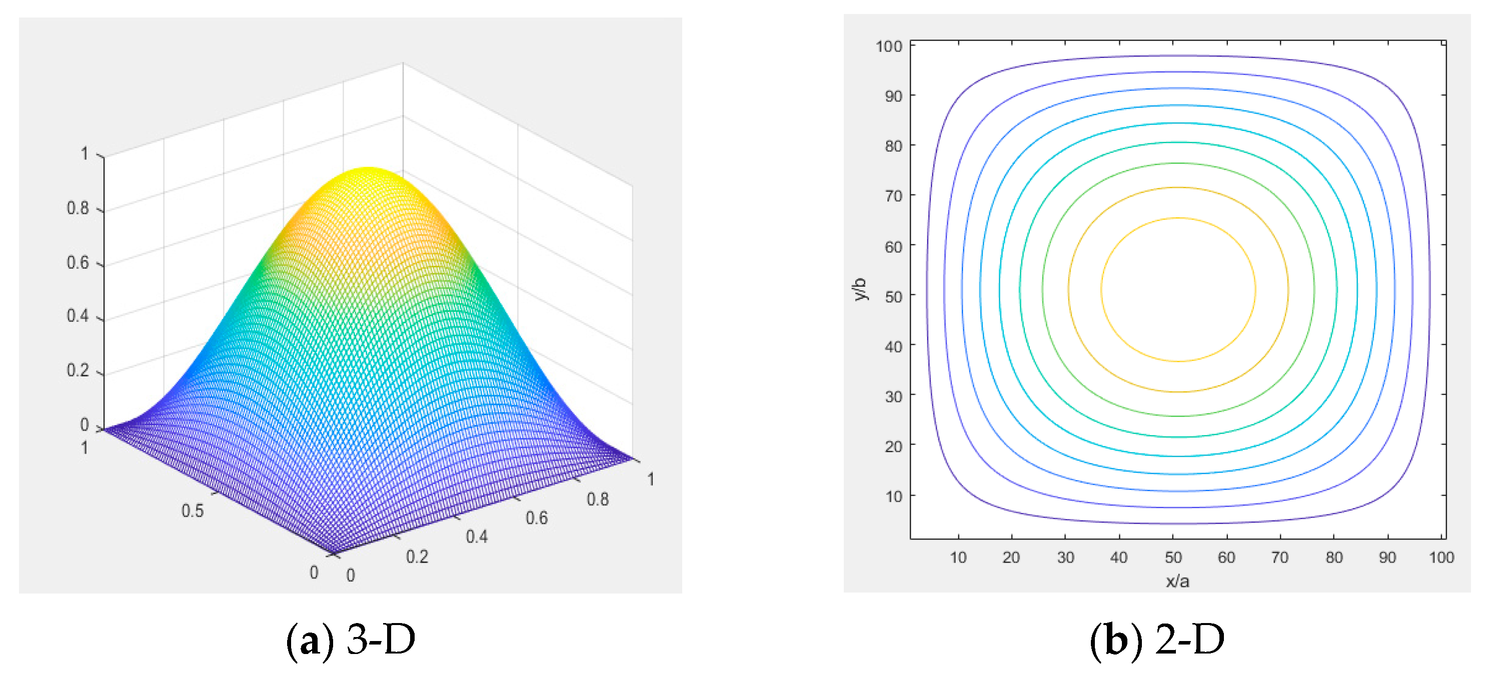
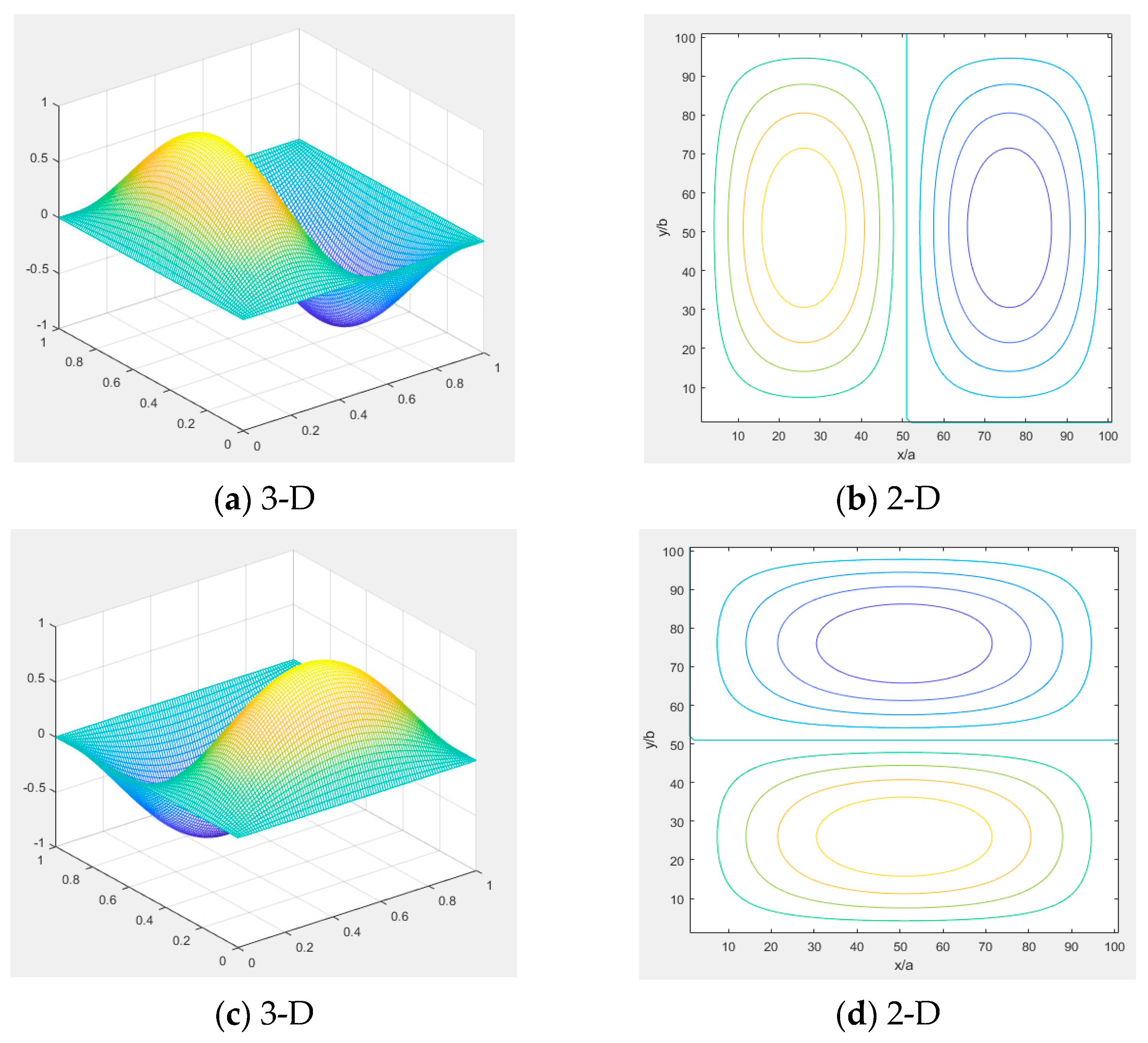
4.2. Natural Frequency and Vibration Modes
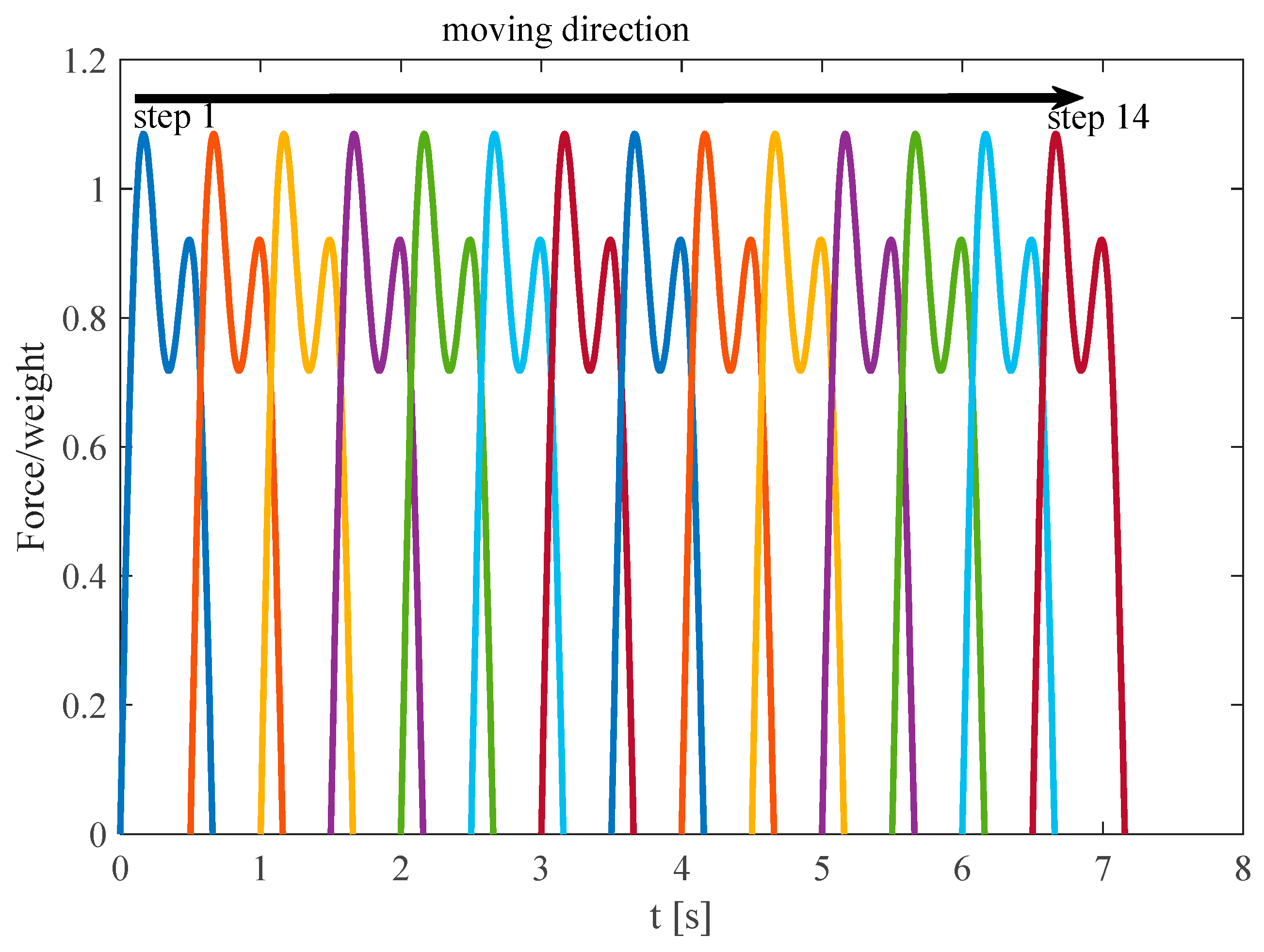
4.3. Calculation of Acceleration Under Human Loads
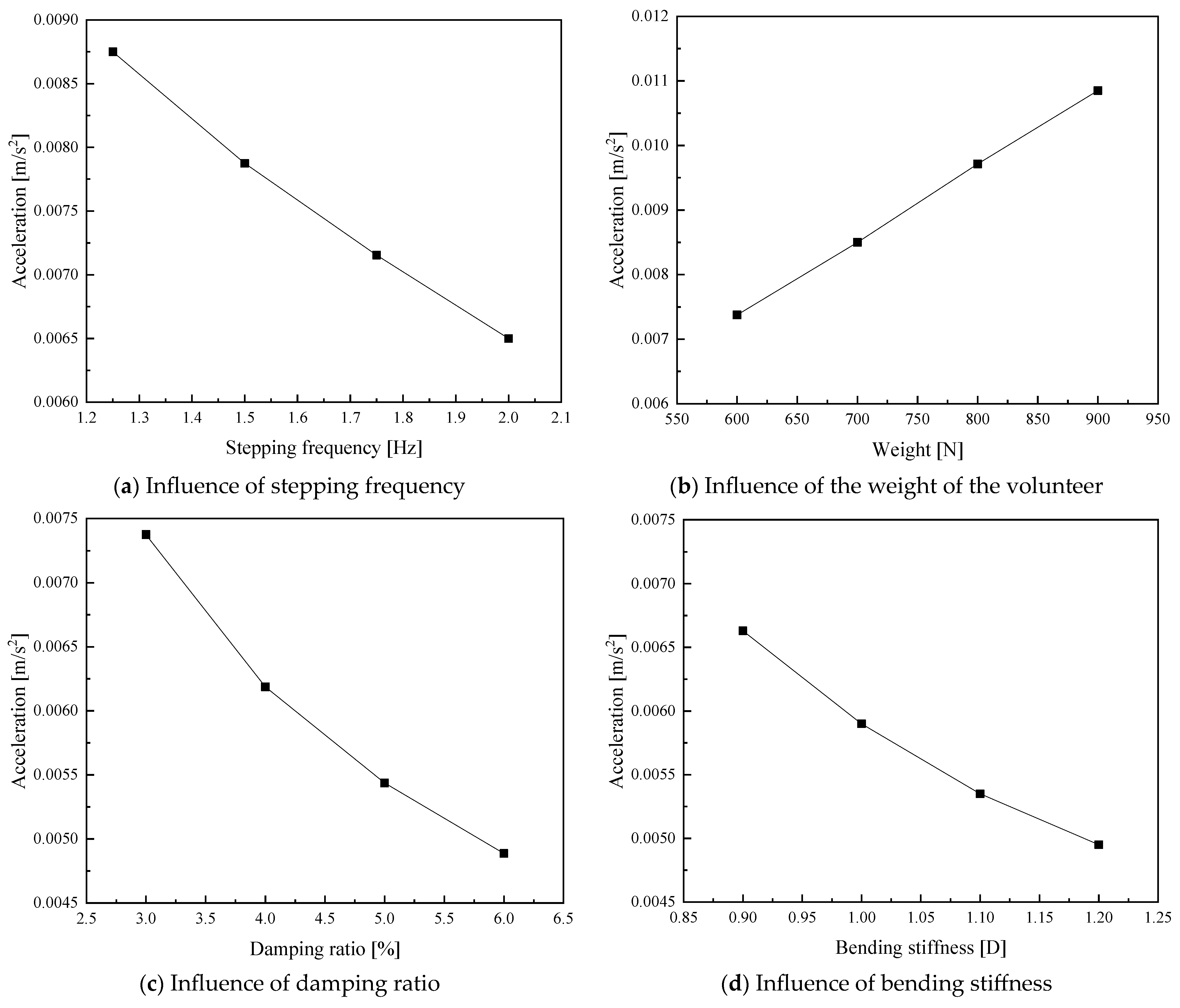
4.4. Parametric Analysis
5. Discussion and Further Application
5.1. Error Discussion
5.2. Further Application
6. Conclusions
- The dynamic behavior of this innovative floor system meets the requirements of GB50010-2010 and ISO 2631. The first-order vibration frequency of the 9.2 m × 9.2 m floor is 11 Hz, larger than 3 Hz. The maximum acceleration for a single person is 0.07 m/s2, smaller than the limited value of 0.35 m/s2. For multiple persons, the maximum acceleration is 0.45 m/s2.
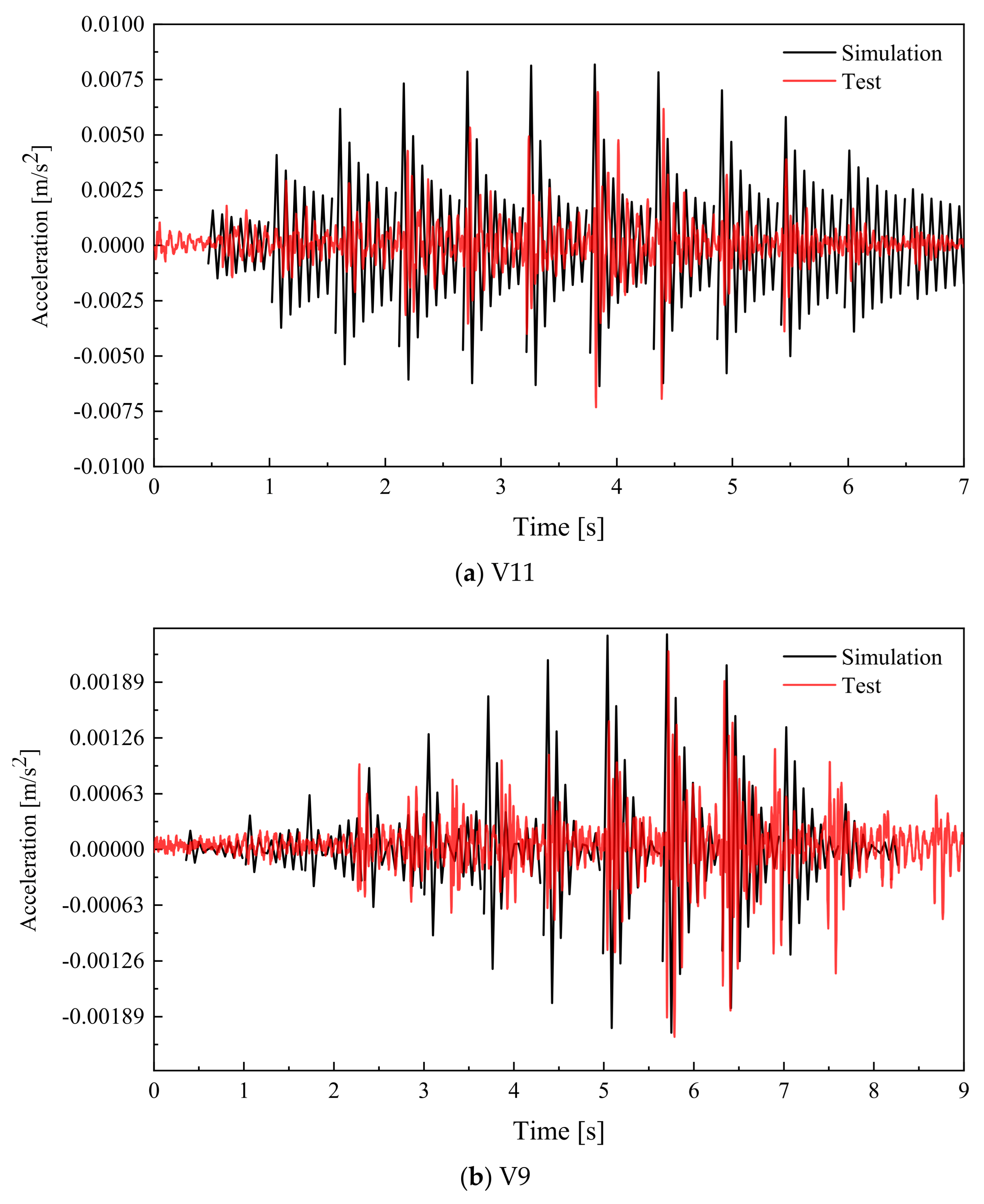
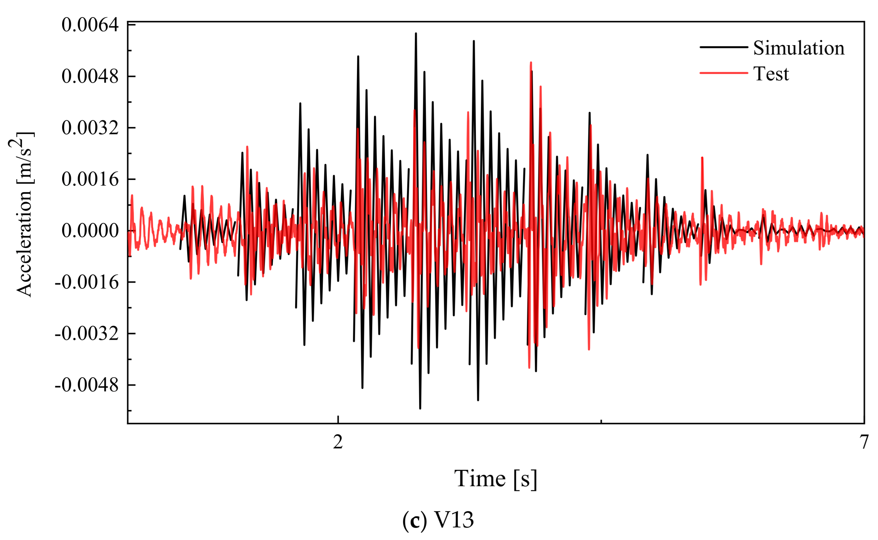
- Elastic plate theory could be applied to predict the natural frequency and acceleration, with the bending stiffness obtained from the experiment. The errors of elastic vibration theory in calculating the first three vibration mode shapes and natural frequencies are approximately 10%. And the absolute error of the acceleration time–history curve is less than 10%, demonstrating its efficiency in predicting the vibration behaviors of this innovative assembled integrated two-way multi-ribbed composite floor system.
- The bending stiffness and damping ratio are the key factors influencing the vibration acceleration of this innovative floor system. Considering the costs, it is recommended that some construction strategies be adopted to enhance the damping ratio and control the vibration of this innovative floor system.
- For similar vibration tests, it is recommended to put acceleration meters at both the top and bottom of the test specimen. Furthermore, it is recommended that more volunteers than the design code requires are needed, since the relationship between the maximum acceleration and multi-person load is nonlinear.
Author Contributions
Funding
Data Availability Statement
Conflicts of Interest
Symbols and Notation List
| a | in-plane horizontal length of the floor | state matrix of a multi-DOF system | |
| maxmimum acceleration under human load | B | state matrices matrix of a multi-DOF system | |
| b | in-plane vertical length of the floor | C | damping matrix of a multi-DOF system |
| Bk | Fourier coefficient | D | observation matrix |
| D | bending stiffness of the floor system | E | feedthrough (or direct transmission) matrix |
| natural frequency, i and j indicate the number of half-waves in the x and y direction. | K | stiffness matrix of a multi-DOF system | |
| fs | walking step rate | M | mass matrix of a multi-DOF system |
| force from a single footfall | X | displacement of a multi-DOF system | |
| m | average mass of the floor system | u(t) | white noise from the earth |
| G | pedestrian weight | xk | acceleration and velocity of a multi-DOF system due to the white noise |
| g | gravity acceleration | yk | observed acceleration, velocity and displacement of a multi-DOF system |
| t | time | δ(x) | Dirac function. |
| Te | duration of a single footstep | ωi | ith angular frequency of a multi-DOF system |
| w | out-of-plane deflection of the floor system | ξi | ith damping ratio of a multi-DOF system |
| vibration mode shape | |||
| x | in-plane horizontal coordinate | ||
| y | in-plane vertical coordinate |
References
- Ding, D. Calculation of Reinforced Concrete Floor; Press of science and technology: Shanghai, China, 1954. (In Chinese) [Google Scholar]
- Safar, A.; Lou, K.B. A study of the action of the beam and beamless (flush) floor slabs of the multistorey buildings. Erciyes Üniversitesi Fen Bilim. Enstitüsü Fen Bilim. Derg. 2007, 23, 127–135. [Google Scholar]
- Newmark, N.M. Proposed design specifications for two-way floor slabs. J. Proc. 1950, 46, 597–607. [Google Scholar]
- Nilson, A.H.; Walters, D.B. Deflection of two-way floor systems by the equivalent frame method. J. Proc. 1975, 72, 210–218. [Google Scholar]
- Huang, Y.; Ma, K.; Zhang, H.; Xiao, J.; Jiang, S. Study and application of Vierendeel-sandwich-plate floor framing in multistoried and tall building. J. Build. Struct. 1997, 18, 55–64. [Google Scholar]
- Pan, Y. Study of Load-Bearing Properties of PK Prestressed Composite Slab. Doctoral Dissertation, University of Hunan, Changsha, China, 2009. (In Chinese). [Google Scholar]
- Pang, R. Research on the Mechanical Property and Seismic Design Method of New Type Precast RC Diaphragms. Master Dissertation, Southeast University, Nanjing, China, 2011. (In Chinese). [Google Scholar]
- Naito, C.; Cao, L.; Peter, W. Precast concrete double-tee connections, part 1: Tension behavior. PCI J. 2009, 54, 49. [Google Scholar] [CrossRef]
- Spadea, S.; Rossini, M.; Nanni, A. Design analysis and experimental behavior of precast concrete double-tee girders prestressed with carbon-fiber-reinforced polymer strands. PCI J. 2018, 63, 72–84. [Google Scholar] [CrossRef]
- Jiang, Q.; Zhang, K.; Feng, Y.; Chong, X.; Wang, H.; Lei, Y.; Huang, J. Out-of-plane flexural behavior of full precast concrete hollow-core slabs with lateral joints. Struct. Concr. 2020, 21, 2433–2451. [Google Scholar] [CrossRef]
- de Lima Araújo, D.; Sales, M.W.R.; Silva, R.P.M.; Antunes, C.D.F.M.; de Araújo Ferreira, M. Shear strength of prestressed 160 mm deep hollow core slabs. Eng. Struct. 2020, 218, 110723. [Google Scholar] [CrossRef]
- Ghayeb, H.H.; Razak, H.A.; Sulong, N.R. Performance of dowel beam-to-column connections for precast concrete systems under seismic loads: A review. Constr. Build. Mater. 2020, 237, 117582. [Google Scholar] [CrossRef]
- Chen, Y.; Shi, H.R.; Wang, C.L.; Wu, J.; Liao, Z.Q. Flexural mechanism and design method of novel precast concrete slabs with crossed bent-up rebar. J. Build. Eng. 2022, 50, 104216. [Google Scholar] [CrossRef]
- Huang, Y.; Yang, J.; Zhong, C. Flexural performance of assembly integral floor structure voided with steel mesh boxes. J. Build. Eng. 2022, 54, 104693. [Google Scholar] [CrossRef]
- Deng, B.Y.; Tan, D.; Li, L.Z.; Zhang, Z.; Cai, Z.W.; Yu, K.Q. Flexural behavior of precast ultra-lightweight ECC-concrete composite slab with lattice girders. Eng. Struct. 2023, 279, 115553. [Google Scholar] [CrossRef]
- Zeng, X.; Feng, Y.; Ruan, S.; Xu, M.; Gong, L. Experimental and Numerical Study on Flexural Behavior of a Full-Scale Assembled Integral Two-Way Multi-Ribbed Composite Floor System. Buildings 2023, 13, 2517. [Google Scholar] [CrossRef]
- Zhang, W.; Feng, Y.; Zeng, X.; Xu, M.; Gong, L.; Rui, L. Flexural Performances of Novel Wet Joints with Sleeve Connections in Precast Composite Floor System. Buildings 2024, 14, 822. [Google Scholar] [CrossRef]
- Tilden, C.J. Kinetic effects of crowds. Trans. Am. Soc. Civ. Eng. 1913, 76, 2107–2126. [Google Scholar] [CrossRef]
- Fuller, A.H. Dynamic effects of moving floor loads-stresses measured in the floor and balcony of a college gymnasium. Am. Arch. Arch. 1924, 126, 455–456. [Google Scholar]
- Greimann, L.F.; Klaiber, F.W. Dynamic forces induced by spectators. J. Struct. Div. 1978, 104, 348–351. [Google Scholar] [CrossRef]
- Ebrahimpour, A.; Sack, R.L. Modeling dynamic occupant loads. J. Struct. Eng. 1989, 115, 1476–1496. [Google Scholar] [CrossRef]
- Ebrahimpour, A.; Sack, R.L. Design live loads for coherent crowd harmonic movements. J. Struct. Eng. 1992, 118, 1121–1136. [Google Scholar] [CrossRef]
- Pernica, G. Dynamic load factors for pedestrian movements and rhythmic exercises. Can. Acoust. 1990, 18, 3–18. [Google Scholar]
- Lenzen, K.H. Vibration of steel joist-concrete slab floors. Eng. J. 1966, 3, 133–136. [Google Scholar] [CrossRef]
- Li, Q.; Fan, J.; Nie, J. Stochastic vibration of a long-span floor under crowd-induced rhythmic excitation. J. Vib. Shock 2012, 31, 9–15. (In Chinese) [Google Scholar]
- Liu, J.; Zheng, X.; Li, J. Vibration serviceability of composite slab with prefabricated concrete straight ribbed panels. J. Build. Struct. 2019, 40 (Suppl. S1), 41–46. (In Chinese) [Google Scholar]
- Cui, W.X.; Chen, Z.F.; Yin, W.Y.; Liu, S.C. Serviceability of a new kind of precast hollow cross-grids floor system. Appl. Mech. Mater. 2017, 873, 158–163. [Google Scholar] [CrossRef]
- GB50010-2010; National Standard of the People’s Republic of China: Code for Design of Concrete Structures. China Architecture & Building Press: Beijing, China, 2015.
- GB/T 228.1-2010; National Standard of the People’s Republic of China: Metallic Materials—Tensile Testing—Part 1: Method of Test at Room Temperature. Standard Press of China: Beijing, China, 2015.
- JG/T 163-2013; Coupler for Rebar Mechanical Splicing. Standards Press of China: Beijing, China, 2013.
- Kalman, R.; Ho, B. Effective construction of linear state variable models from input output data. In Proceedings of the 3rd Allerton Conference, Monticello, VA, USA, 20–22 October 1965; pp. 449–459. [Google Scholar]
- Van Overschee, P.; De Moor, B. Subspace Identification for Linear Systems: Theory—Implementation—Applications; Springer Science & Business Media: Berlin/Heidelberg, Germany, 2012. [Google Scholar]
- Allen, G.R. Ride Quality and International Standard ISO 2631 (“Guide for the Evaluation of Human Exposure to Whole Body Vibration”); NASA, Technical Report No. NASA-TM-X-3295; NASA: Washington, DC, USA, 1975. [Google Scholar]
- Chen, J.; Wang, H.; Wang, L. Experimental investigation on single person’s jumping load model. Earthq. Eng. Eng. Vib. 2015, 14, 703–714. [Google Scholar] [CrossRef]
- Zhang, S.; Xu, L. Human-induced vibration of cold-formed steel floor systems: Parametric studies. Adv. Struct. Eng. 2020, 23, 2030–2043. [Google Scholar] [CrossRef]
- Pang, R.; Liu, J.; Zhou, F.; Dang, L.; Yang, Y.; Wang, W.; Duan, J. Vibration behavior of innovative discretely connected precast concrete sandwich floors. J. Build. Eng. 2024, 82, 108313. [Google Scholar] [CrossRef]
- Li, Q.; Fan, J.; Nie, J.; Li, Q.; Chen, Y. Crowd-induced random vibration of footbridge and vibration control using multiple tuned mass dampers. J. Sound Vib. 2010, 329, 4068–4092. [Google Scholar] [CrossRef]
- JGJ 3-2010; Technical Specification for Concrete Structures of Tall Buildings. China Architecture & Building Press: Beijing, China, 2010.


| Materials | Diameters of Rebar [mm] | Yield Stress [MPa] | Ultimate Stress [MPa] | Young’s Modulus [MPa] |
|---|---|---|---|---|
| Rebars | 20 | 420.31 | 620.06 | 217,696 |
| 12 | 451.24 | 616.58 | 209,643 | |
| 6 | 436.73 | 580.46 | 213,487 | |
| Coupler | 20 | 414.57 | 608.02 | 176,867 |
| Positions of Concrete | Cubic Compressive Stress [MPa] | Young’s Modulus [MPa] |
|---|---|---|
| Cast-in-situ section | 36.75 | 30,043 |
| Precast panels | 39.47 | 29,567 |
| NO of Vibration Modes | Frequencies [Hz] | Damping Ratio [%] | Vibration Mode Shapes |
|---|---|---|---|
| 1 | 11.718 | 3.304 | 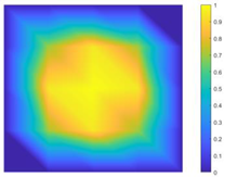 |
| 2 | 27.314 | 0.855 | 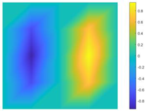 |
| 3 | 43.510 | 0.793 | 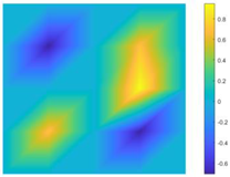 |
| Frequencies [Hz] | First Order | Errors [%] | Second Order | Errors [%] | Third Order | Errors [%] |
|---|---|---|---|---|---|---|
| Test | 11.718 | - | 27.314 | - | 43.510 | - |
| Analytical method | 12.20 | +4.11% | 30.49 | +11.63 | 48.78 | +12.11% |
| Stepping Frequencies [Hz] | Weight of a Single Person [N] | Damping Ratio [%] | Bending Stiffness [D] |
|---|---|---|---|
| 1.25 | 600 | 3 | 0.9 |
| 1.5 | 700 | 4 | 1.0 |
| 1.75 | 800 | 5 | 1.1 |
| 2 | 900 | 6 | 1.2 |
Disclaimer/Publisher’s Note: The statements, opinions and data contained in all publications are solely those of the individual author(s) and contributor(s) and not of MDPI and/or the editor(s). MDPI and/or the editor(s) disclaim responsibility for any injury to people or property resulting from any ideas, methods, instructions or products referred to in the content. |
© 2025 by the authors. Licensee MDPI, Basel, Switzerland. This article is an open access article distributed under the terms and conditions of the Creative Commons Attribution (CC BY) license (https://creativecommons.org/licenses/by/4.0/).
Share and Cite
Gong, L.; Feng, Y.; Zhang, W.; Xu, M.; Zeng, X. Vibration Performances of a Full-Scale Assembled Integral Two-Way Multi-Ribbed Composite Floor. Buildings 2025, 15, 1551. https://doi.org/10.3390/buildings15091551
Gong L, Feng Y, Zhang W, Xu M, Zeng X. Vibration Performances of a Full-Scale Assembled Integral Two-Way Multi-Ribbed Composite Floor. Buildings. 2025; 15(9):1551. https://doi.org/10.3390/buildings15091551
Chicago/Turabian StyleGong, Liang, Yan Feng, Wenbin Zhang, Ming Xu, and Xiangqiang Zeng. 2025. "Vibration Performances of a Full-Scale Assembled Integral Two-Way Multi-Ribbed Composite Floor" Buildings 15, no. 9: 1551. https://doi.org/10.3390/buildings15091551
APA StyleGong, L., Feng, Y., Zhang, W., Xu, M., & Zeng, X. (2025). Vibration Performances of a Full-Scale Assembled Integral Two-Way Multi-Ribbed Composite Floor. Buildings, 15(9), 1551. https://doi.org/10.3390/buildings15091551