1. Introduction
In recent years, architects and engineers have shown growing interest in lightweight, geometrically expressive shell structures that function both as primary structural systems and as enclosures, providing integral support and shading. Such geometric prototypes hold promise for applications in freeform roofs, open-air pavilions, installation-based architecture, and innovative façade systems, where the shape of the shell and its designed surface patterns serve both structural and supplementary purposes. Several pioneering real-world projects have demonstrated both the potential and the challenges of this approach. For instance, Branch Technology’s 3D-printed pavilion achieved an open-cell lattice shell with “endless geometric form” and high strength-to-weight efficiency by prefabricating a cellular matrix as the support structure [
1]. Research pavilions by academic institutes further underscore the idea: the University of Stuttgart’s ICD/ITKE biomimetic pavilion series has shown that nature-inspired double-layered shells can be highly material-efficient, with performance derived from their geometric morphology [
2]. Likewise, an experimental pavilion at ETH Zurich demonstrated a lightweight spatial lattice as a temporary sun-shading canopy for a public plaza [
3]. At the architectural scale, Zaha Hadid Architects have adopted cellular façade systems, for example, the honeycomb lattice skin of the KAPSARC project [
4], to create a structural envelope that minimizes material while providing a self-shading, protective shell in a desert climate. These precedents highlight the promise of lightweight, shading-capable, free-form shells, but also clarify the technical complexities in achieving structural efficiency, constructability, and environmental performance.
The appeal of geometrically porous shell structures lies in their ability to optimize material usage and multi-functionality beyond what conventional solid shells can offer. A porous shell can similarly adapt its internal topology in response to stress distributions, creating a stiff, lightweight frame that supports an outer surface for weather protection and shading. By varying the density and topology of the shell’s lattice, one can place material only where it is structurally needed, resulting in significantly higher stiffness-to-weight performance and resource efficiency. This concept is inspired by biological systems—for example, bone, wood, and plant tissue achieve remarkable strength with minimal mass through graded porosity and hierarchical structure [
5,
6]. In contrast to a homogeneous shell, a GPS shell can “adaptively distribute” its material according to local demands. GPS, characterized by spatially varying porosity and directional material distribution, have emerged as highly promising, offering superior mechanical performance, weight reduction, and multifunctionality compared to homogeneous structures [
7,
8]. The potential benefits include substantial weight reduction, smoother stress flow, and integration of functional features.
However, conventional homogeneous or simpler porous designs often fall short in performance metrics. For example, gyroid and Triply periodic minimal surfaces-based porous materials show significant differences in stress distribution and stiffness compared to traditional lattice structures, with smoother surfaces improving load transfer and mechanical efficiency [
9]. Similarly, homogeneous shell structures are prone to stress concentration and delamination, while functionally graded shells exhibit smoother deformation profiles and better bending response [
10]. In short, these limitations highlight the necessity of further research into advanced structural solutions like GPS. The goal is to create simultaneously structurally optimized and environmentally responsive shells, addressing increasing architectural sustainability and efficiency demands.
To realize a porous shell structure in practice, a promising strategy is to use a spatial Voronoi tessellation as the structural framework. Voronoi diagrams inherently produce irregular, cell-like patterns that resonate with many natural structures. When applied to a 3D shell geometry, a Voronoi tessellation partitions the surface into an organic network of cells, yielding a lattice of beams with varying sizes and shapes. Spatial Voronoi diagrams have increasingly become a valuable approach for designing porous, cellular structural systems. Voronoi-based designs have found extensive applications in aerospace, biomedical engineering, and architectural practice, highlighting their versatility and adaptability. Lin et al. [
11] demonstrated the potential of using spatial Voronoi diagrams with GA to optimize 3D porous materials inspired by bird wing bones. Their method generated Voronoi structures, evaluated their compressive properties via finite element simulations, and evolved optimal structures through GA. Optimized structures exhibited improved mechanical properties, underscoring the value of spatial Voronoi diagrams in structural optimization. A recent study by Fontalvo García et al. [
12] specifically focused on the utilization of spatial Voronoi diagrams in the structural optimization of flat roofs. The authors proposed a GA-based methodology to optimize the topology of Voronoi flat roofs, aiming to minimize the weight of the structure while adhering to technical and architectural constraints. Their research highlighted the effectiveness of spatial Voronoi diagrams in generating aesthetically pleasing and structurally efficient roof designs. By exploring the multimodal nature of the search space and tuning the GA parameters, the authors were able to demonstrate the feasibility and benefits of using spatial Voronoi diagrams in architectural structural optimization.
TO, specifically the SIMP method, has established itself as an essential computational technique for optimal material distribution within complex structural geometries [
13]. Integrated with FEA, TO identifies critical stress regions, guiding strategic material placement or removal [
14]. While TO is a powerful method to derive efficient structural forms, conventional TO techniques face limitations when applied to architecturally complex shells. Standard TO will indicate where to remove or keep material in a continuum, but it does not inherently produce a discrete pattern or enforce geometric regularity, emphasizing the need for hybrid strategies. Prior research has explored combining TO with spatial patterning approaches. For instance, Cao et al. proposed a stress-field-driven Voronoi generation method enabling gradient and anisotropic mechanical behavior simultaneously [
15], while Li et al. developed variable-periodic Voronoi tessellation, achieving over 50% improvement in compliance and damage resistance through multiscale optimization [
16]. Moreover, Kim and Lee introduced a multiscale SIMP-based framework coupling macro-level density optimization with Voronoi-like microstructures using quaternion dehomogenization [
17]. Despite these advances, substantial gaps remain in unifying mechanical performance, spatial adaptability, and architectural expressiveness within a coherent optimization framework.
However, few studies have successfully integrated macro-scale topology optimization with Voronoi-based structural discretization in a fully computational pipeline tailored for architectural shells. Most prior works either focus on material distributions without geometric regularization or generate cell structures without incorporating stress responsiveness. Therefore, a need arises for a multi-scale framework that bridges stress-field data with geometric design intent under fabrication constraints.
This study addresses the existing gap by integrating SIMP-based TO, adaptive Voronoi tessellation informed by stress distributions, and bi-objective GA optimization, particularly targeting predefined complex shell geometries. The proposed framework optimizes structural parameters such as Voronoi CP distributions and structural element cross-sectional properties to balance mechanical efficiency and material minimization effectively. A weighted LR step further refines Voronoi structures, creating smoothly varying density gradients aligned with stress requirements and aesthetic considerations. FEA simulations validate the proposed method, confirming enhancements in stress distribution, SWR, and overall material economy, with indicative improvements such as a 79.7% reduction in material volume, and SWR remaining above 2000. Thus, this research provides a robust foundation for applying computationally optimized, aesthetically compelling GPS in advanced architectural designs.
2. Methodology
The computational framework presented in this study integrates advanced optimization and computational geometry techniques to design structurally efficient, aesthetically appealing architectural shells. This section describes our methodology in five sequential parts: geometry definition, SIMP-based TO, adaptive Voronoi tessellation based on stress distribution, GA-based structural refinement with weighted LR-based spatial framework, and FEA performance evaluation.
2.1. Geometry Definition
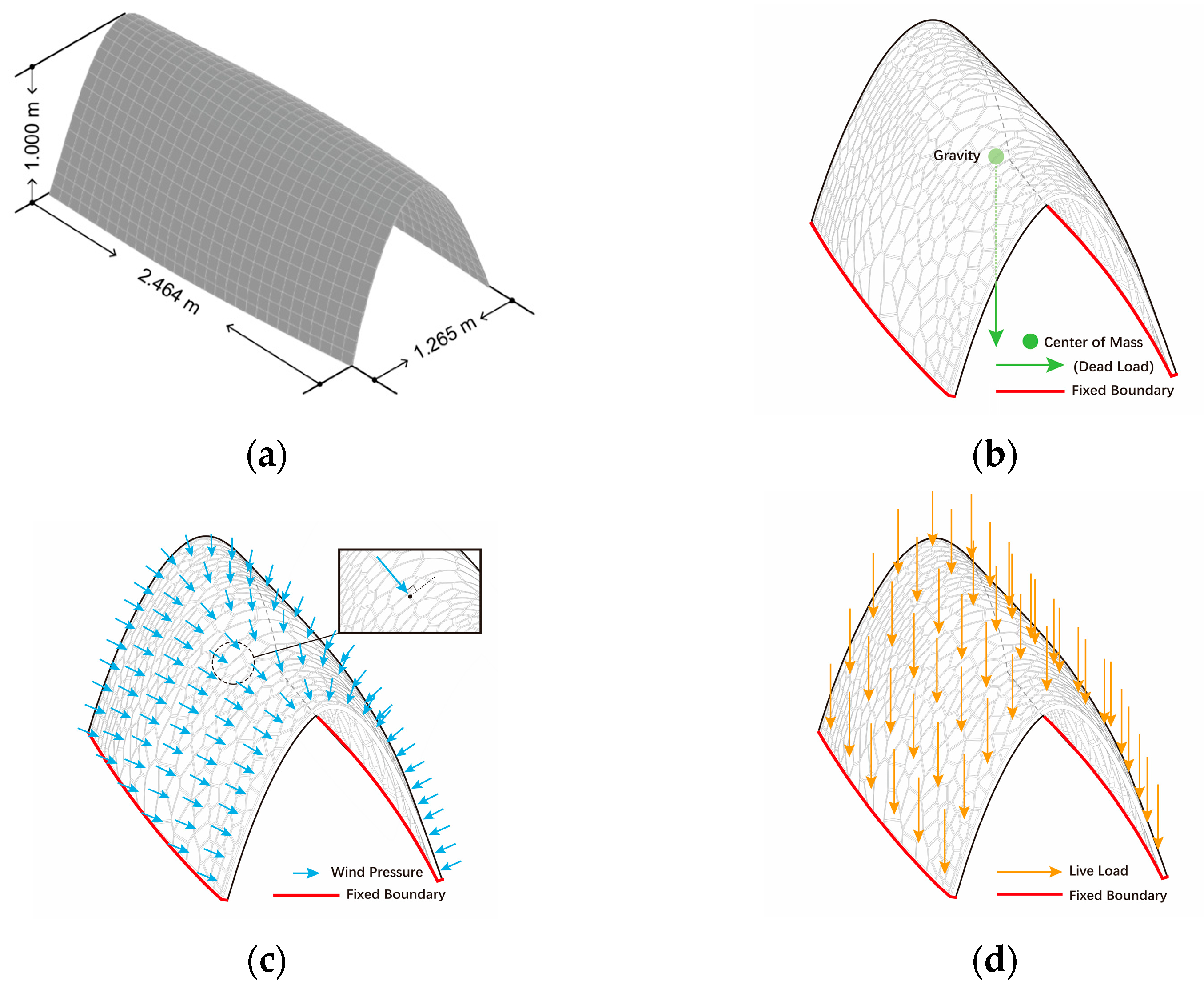
The prototype investigated in this study is a double-curvature architectural shell structure defined within a 2.464 m × 1.265 m × 1.000 m bounding box. A uniform thickness of 25 mm is offset from the test model and forms a baseline shell structure used across all design variants. Although the optimization transforms the continuous surface into a spatial Voronoi framework, at the current scale defined in this study, the shell structure is typically applied in real-world scenarios as a small-scale, standalone shading installation, a landscape installation, an interior ceiling feature, or, in certain cases, as a geometrically complex roof component connected to other architectural structures. In practical architectural applications, it remains necessary to install lightweight skin panels, typically 2–4 mm in thickness, within or above the structural openings. Such panels provide critical functional requirements including shading, weather resistance, and acoustic insulation.
To retain geometric continuity and adaptive design freedom achievable through optimization, this study explicitly assumes the use of large-scale Fused Deposition Modeling (FDM) 3D printing technology for both structural frame members and infill skin panels. It is important to acknowledge that FDM-printed structures typically exhibit anisotropic and inhomogeneous mechanical behaviors due to the layer-by-layer deposition process. Thus, printed structures might exhibit directional dependency in mechanical properties, potentially influencing stiffness and strength characteristics. Further studies incorporating anisotropic and heterogeneous material modeling are recommended to match the real-world behavior of FDM-printed structural components closely.
This fabrication route circumvents complexities associated with traditional welding, casting, or formwork-based methods, making it especially suitable for the highly differentiated, spatially varied geometry inherent to Voronoi-based optimization. The Voronoi frame structures are evaluated under standardized loading and boundary conditions described in
Section 3.
2.2. Computational Workflow
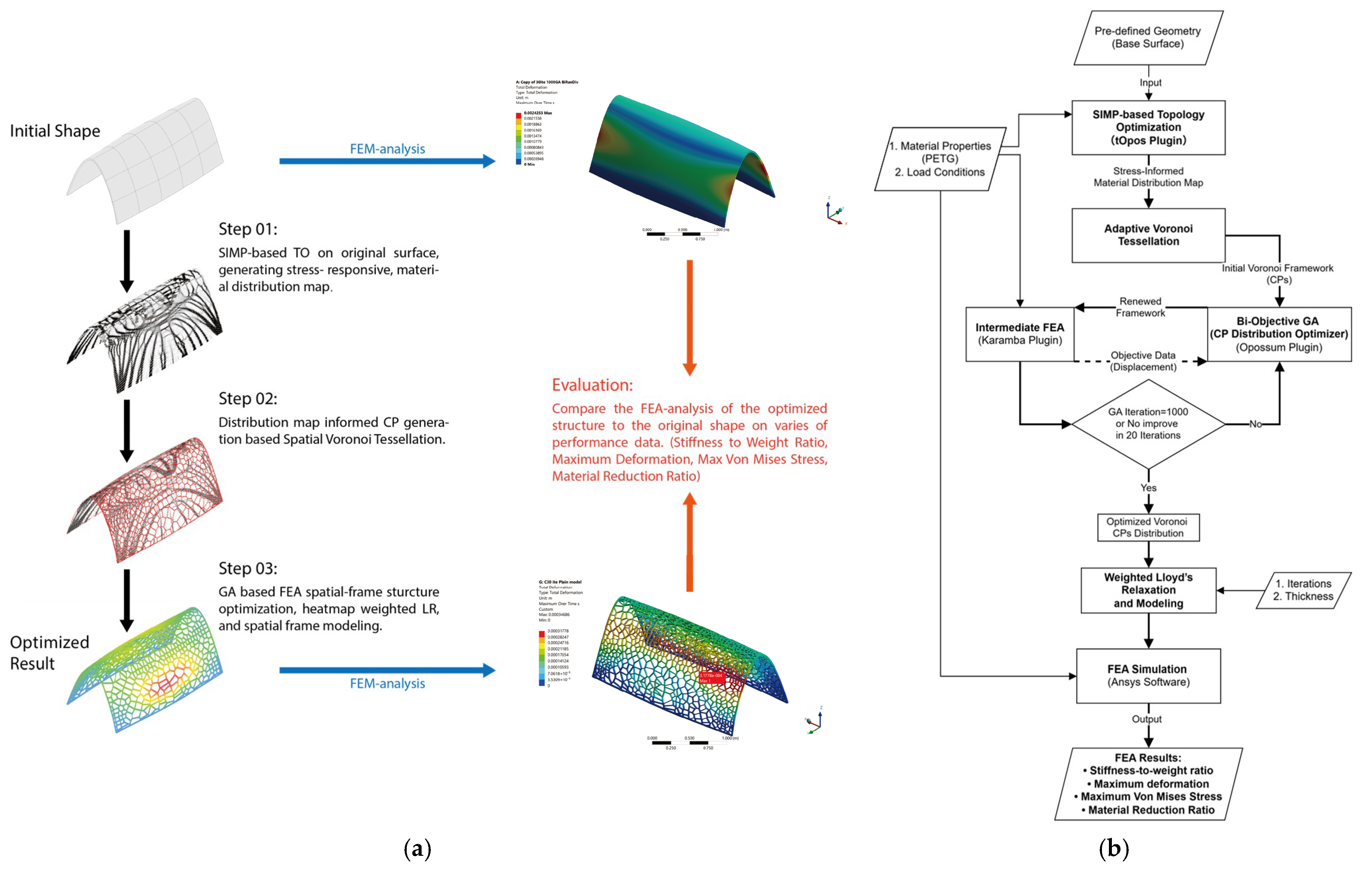
As illustrated in
Figure 1, the proposed method consists of three sequential stages:
2.2.1. SIMP-Based Topology Optimization
The Solid Isotropic Material with Penalization (SIMP) method is a widely used topology optimization technique that determines optimal material distribution within a given design domain. It operates by assigning a relative density value
to each finite element in the structure, where
represents solid material and
indicates void. The key principle of SIMP is to interpolate the material stiffness
as a nonlinear function of density using a penalization power
p > 1, typically formulated as follows:
where
is the Young’s modulus of the solid material. The penalization factor
p (commonly set to 3) suppresses intermediate densities and drives the solution toward a nearly binary “0–1” material distribution. By minimizing structural compliance subject to a volume constraint, the SIMP method effectively identifies critical load paths while eliminating structurally redundant regions. A typical SIMP optimization result resembles a truss-like structural pattern, as a material distribution map, where material concentrates along principal stress trajectories, providing a clear basis for stress-informed geometric design.
At this stage, the focus of the process is on performing TO for a given surface to obtain the stress-responsive material distribution map. The generated material distribution map will serve as the guiding data for the next stage of the optimization process.
The initial geometry selected for optimization was a parametrically defined double-curved shell. TO was implemented using the tOpos plugin for Grasshopper, which employs the SIMP method formulated as follows:
where
represents compliance,
the density field,
the applied loads,
the displacements,
the material volume, and the prescribed volume fraction set at 0.4. In this study, a SIMP exponent of 3.0 is employed because it robustly drives the solution toward a nearly binary material distribution [
18]. A high penalization power significantly diminishes the relative stiffness contribution of elements with intermediate density in a compliance-minimization framework (minimizing total strain energy for a given material volume). The choice of
p ≈ 3 is well supported in the literature to obtain a clear 0–1 design; it is the standard value in SIMP yielding black-and-white topologies, and it ensures the interpolation remains physically meaningful [
19,
20]. Notably, this level of penalization tends to produce truss-like, discrete structural layouts in the optimized design, which is beneficial for stress-informed Voronoi-based shell structures. A crisp solid-void solution provides distinct load-bearing ribs along principal stress trajectories and open void regions elsewhere, simplifying the translation of the SIMP result into a lightweight Voronoi frame while maximizing structural efficiency.
The resulting stress distribution data were exported as a normalized scalar field ranging from 0 to 1, serving as critical input for subsequent stress-responsive Voronoi tessellation.
2.2.2. Adaptive Voronoi Tessellation Based on Stress Distribution
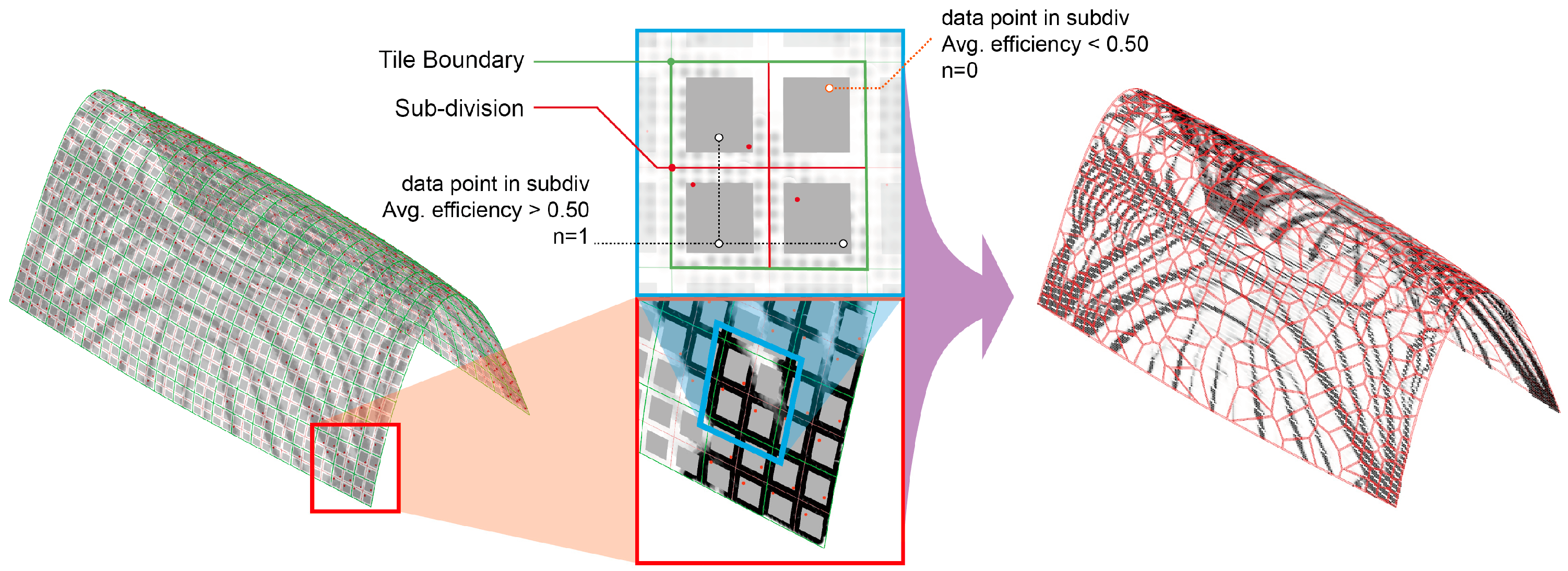
This stage aims to convert the material distribution map data into the average material efficiency value for the subdivided regions of the surface. Based on these data, Voronoi CPs will be generated in the corresponding regions, achieving the stress-responsive tessellation of the Voronoi diagram on the surface. The generated Voronoi geometries and their boundaries will serve as control parameters for the structural framework, guiding the next stage of structure optimization based on a GA and unit optimization using the LR algorithm.
The double-curved shell surface was subdivided into a 19 × 19 parametric grid, yielding 361 surface cells. Each cell was further divided into 4 sub-regions to allow local control point (CP) placement, resulting in a theoretical maximum of 1444 CPs. Flattening the base shell surface (approx. 2.464 m × 2.353 m) yields a projected area of ~5.8 m2, resulting dimension of 12.97 cm × 12.38 cm per cell in the 19 × 19 grid, implying an average CP density of approximately one CP per 40 cm2.
This resolution was determined based on extensive pretesting to ensure that the Voronoi generation, optimization, and FEA stages could all be completed without numerical failure. Increasing the mesh density significantly beyond this value was found to: (i) increase the total number of Voronoi cells, thereby prolonging the full workflow runtime, (ii) increase the risk of generating overly small or ill-conditioned cells during tessellation and meshing, and (iii) introduce complex local topologies that may compromise finite element meshing stability. Conversely, coarser grids (e.g., 13 × 13) failed to capture sufficient stress gradient detail to support meaningful control point adaptation.
Therefore, the 19 × 19 grid represents the finest practical resolution achievable under current computational constraints while preserving geometric adaptivity and simulation stability.
The threshold value of 0.5 was determined through parametric testing, which demonstrated the optimal balance between structural performance and material efficiency. This threshold value corresponds to regions experiencing approximately 50% of the maximum normalized stress. Each quadrant exceeding this threshold received one Voronoi CP, positioned stochastically within the quadrant boundary using a pseudo-random number generator with controlled seed values to ensure reproducibility. This controlled randomization prevented overly deterministic patterns while maintaining structural responsiveness to the underlying stress field.
2.2.3. GA-Based Structural Refinement and Weighted LR-Based Spatial Framework
In the final stage, two main algorithms will be applied to compute the organization of the beams and units, aiming to optimize both the mechanical performance of the structure and the rational distribution of the structural components. Additionally, by incorporating the corresponding experimental setup, the Voronoi diagram will be converted into a solid model for final result comparison and analysis.
This study employed the Opossum plugin to conduct a bi-objective optimization process, targeting the simultaneous minimization of maximum displacement (primary objective) and average displacement (secondary objective) under predefined loading conditions. The optimization was driven by the model-based Radial Basis Function Multi-objective Optimizer (RBFMOpt) solver. Objective evaluations were performed through an integrated FEA loop using Karamba, a parametric structural analysis tool within the Grasshopper environment.
RBFMOpt is a surrogate-assisted multi-objective algorithm that decomposes the problem via weighted scalarization instead of pure Pareto dominance, enabling efficient search with relatively few expensive simulations [
21]. The optimization was limited to 1000 iterations, using a single-cycle augmented Tchebycheff scheme (ε = 0.1) with low-discrepancy weights, disabled initial sampling, and a high Radial Basis Function surrogate filter multiplier (×150), to efficiently explore the solution under constrained evaluation budget [
22].
Together, these settings leverage RBFMOpt’s strength in finding reasonable solutions with minimal simulations. RBFMOpt has been shown to attain high-quality fronts within only tens of evaluations on expensive problems, which is crucial for the iterative Voronoi shell optimization framework [
23].
Unlike typical GA settings where decision variables map directly to structural properties, the optimization in this study employs GA-controlled random seeds to control the spatial distribution of Voronoi control points. Therefore, conventional convergence behavior is not expected in this context. Instead of relying on early stopping or fitness-guided convergence monitoring, the algorithm was executed for a fixed number of generations, and the best-performing solutions were selected from the resulting population.
Following GA optimization, a weighted LR process was applied to the Voronoi CPs. The standard Lloyd algorithm was modified by incorporating a data-driven weighting system to control the relaxation movement vector according to the following formulation:
where
represents the relaxation weight factor for the CP
, and
denotes the normalized stress value (0–1) at each of the 20 nearest data points to the destination position in each iteration. This adaptive weighting system resulted in movement coefficients ranging from 0.01 in high-stress regions to 0.4 in low-stress areas, preserving the structural responsiveness to stress concentrations while allowing greater regularization in non-critical regions.
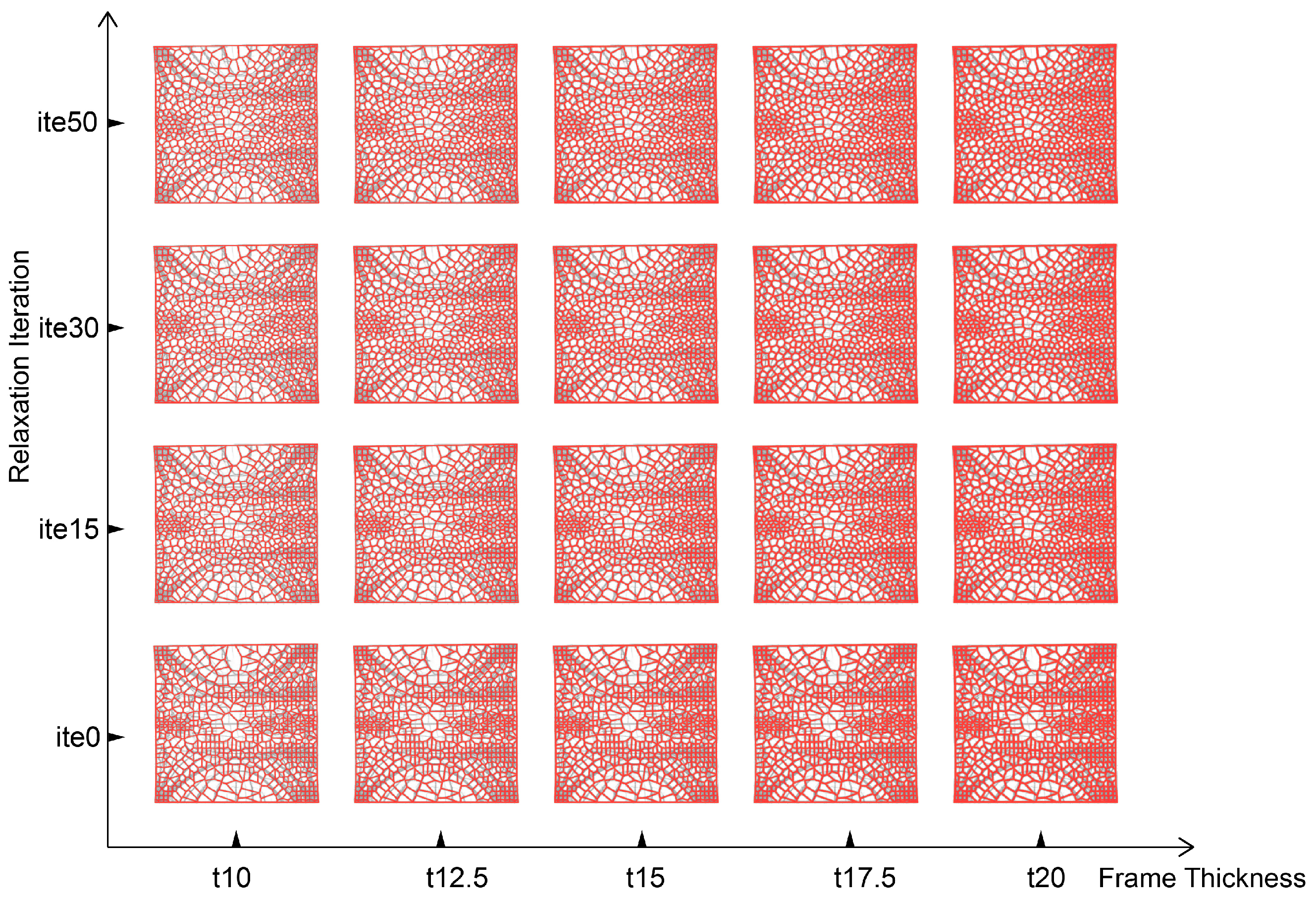
A parametric study was conducted across four distinct relaxation iteration counts (0, 15, 30, and 50 iterations) combined with five different beam thickness configurations (10 mm, 12.5 mm, 15 mm, 17.5 mm, 20 mm), yielding 20 design variants. These variants were systematically evaluated to identify optimal configuration parameters balancing structural performance with material efficiency.
2.3. FEA and Performance Evaluation
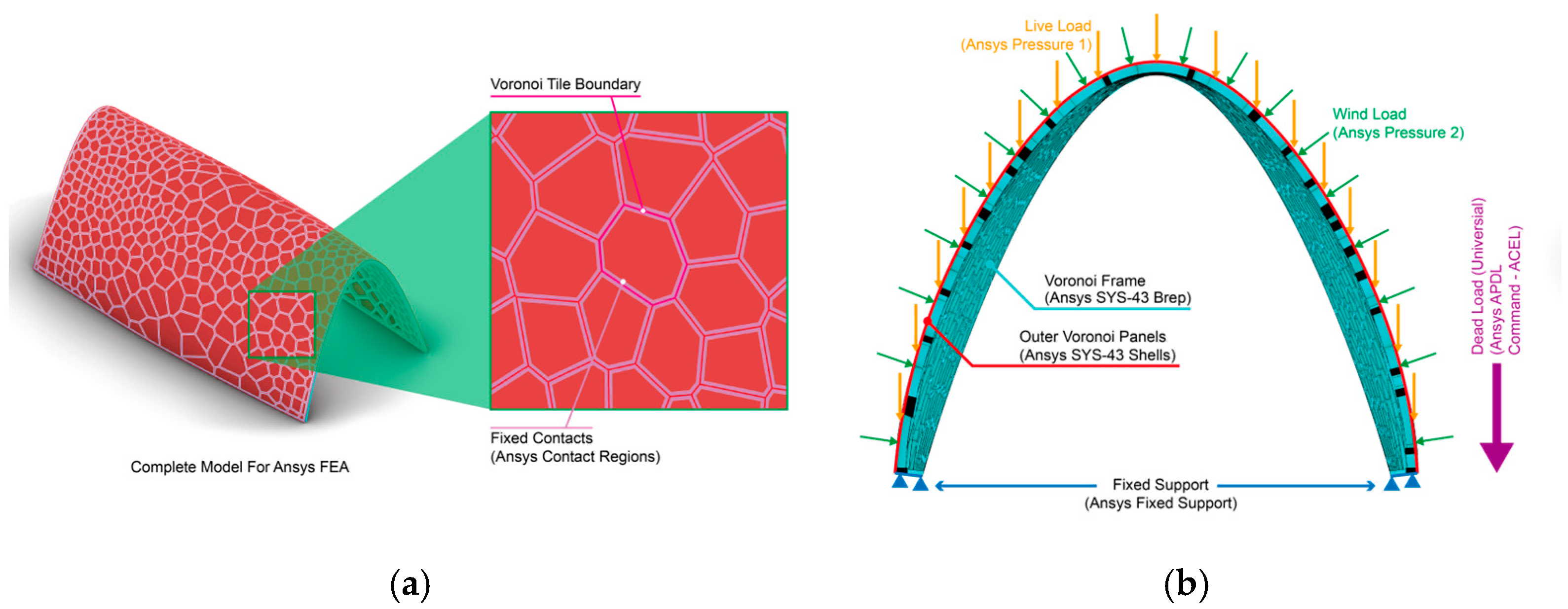
The final structural framework generated via Voronoi optimization was subjected to comprehensive FEA using ANSYS Mechanical 2024 R1. The simulation environment in ANSYS is illustrated in
Figure 2, where the complete model, comprising a solid spatial Voronoi frame structure and a set of corresponding thin shell components representing cladding panels, is imported as the basis for FEA. Each shell component is bonded (non-sliding contact) to its adjacent Voronoi frame elements to simulate the actual attachment conditions of cladding panels in practice. The shell components are assigned with a very small thickness, and no edge contact is defined between adjacent cladding panels to avoid interference with the structural accuracy of the frame simulation.
As shown in
Figure 2b, all loads are applied to the outer cladding components. Forces are transmitted to the Voronoi frame through the bonded contact regions. The yellow arrows indicate the direction of live loads applied to the shell components and the corresponding mechanical load components in ANSYS, while the green arrows represent the direction of wind loads and their respective components. A global gravitational load is applied to the entire model using the
ACEL function within the APDL command set in ANSYS. All the applicable loads were scaled up by its safety factors. Details regarding load types, safety factors, and load combinations can be found in
Section 3.1.
PETG was modeled in ANSYS as a temperature-dependent isotropic material, with mechanical properties defined via a tabulated elastic dataset. At 20 °C, Young’s modulus was set to 2.21 GPa, Poisson’s ratio to 0.38, and density to 1270 kg/m3. The material model also included multilinear isotropic hardening behavior, with a yield strength of 53 MPa and ultimate strength of 60 MPa. This allowed the simulations to incorporate both elastic and limited plastic response under structural loading.
Due to the wide variation in member thickness across different experimental groups and the geometric complexity of the spatial Voronoi frames, a uniform global mesh size could not be applied across all simulations. Instead, for each experimental group with consistent member thickness, the mesh size was locally adapted and set to half the cross-sectional thickness of the beam elements. This approach ensures that slender members are sufficiently discretized to capture bending behavior, while thicker elements avoid unnecessary mesh refinement that could increase computational cost without added accuracy.
Furthermore, to enhance mesh generation robustness and minimize the risk of remeshing failures due to sharp edges or complex intersections, Adaptive Mesh Sizing in ANSYS was enabled. This allows the mesher to locally refine or coarsen elements based on geometric features while still honoring the specified target mesh size per group. All FEA models were successfully meshed using this strategy, and structural results were extracted from the Voronoi frame domains for subsequent evaluation.
A systematic parametric study was conducted across 20 design variants. Results were plotted and analyzed, then benchmarked against the baseline shell structure with equivalent loading and boundary conditions. Performance assessment metrics included:
Stiffness to Weight Ratio (SWR): A measure of structural efficiency, representing the ratio of stiffness to weight, indicating how much stiffness is achieved per unit of weight.
Maximum Deformation (MD): Measured at the most critical location under combined loading.
Maximum Von Mises (MVM) Stress: Analyzed for maximum value throughout the structure.
Material Reduction Ratio (MRR): Representing the percentage of material volume saved through optimization.
2.4. Software Implementation and Methodological Innovations
The proposed computational framework was implemented using integrated software tools to ensure practical applicability and efficient structural optimization workflows. Rhinoceros 3D with Grasshopper was utilized for parametric modeling, adaptive Voronoi tessellation generation, and visualization of optimized structures. The tOpos plugin for Grasshopper facilitated SIMP-based TO directly within the parametric modeling environment. FEA for structural validation at the GA optimization stage was conducted using the Karamba plugin within Grasshopper, enabling real-time performance feedback. Additionally, the final FEA was performed on ANSYS Mechanical 2024 R1 to allow the modifiability to the physical properties of the test environment and ensure an accurate result that is close to the actual situation.
The primary methodological innovation of this research lies in its multi-scale hierarchical optimization approach, which systematically addresses structural performance across three distinct levels:
Macroscale (Global Form): SIMP-based TO identifies optimal material distribution patterns across the entire shell structure, establishing primary load paths and structural hierarchies.
Mesoscale (Cellular Topology): Adaptive Voronoi tessellation with stress-responsive CP distribution creates a cellular framework that balances structural efficiency with fabrication constraints.
Microscale (Member Properties): Parametric definition of individual structural members with variable cross-sections ensures optimal material allocation and stress management at the element level.
This hierarchical framework establishes a high-dimensional optimization space that captures the complex interdependencies between geometric configuration and mechanical performance. These contributions collectively enhance the structural efficiency, constructability, and scalability of GPS in architectural and structural engineering applications.
3. Simulation Experiments
This section presents the experimental validation of the optimized Voronoi-based structural framework through comparative performance analysis against a baseline shell structure. The validation methodology quantifies structural weight reduction, material efficiency, displacement control, stress distribution, and computational feasibility for practical architectural applications.
3.1. Geometry Presets and Environmental Settings
This experiment aims to adapt GPS for application at the architecture scale. As the experimental foundation, a double-curvature arched surface is selected. This test model serves to demonstrate the critical role of the proposed optimization method in refining complex geometries with non-uniform stress distributions.
As shown in
Figure 3, The structural demands on the surface are determined according to international building regulations for roof components. The generalized load equation combines dead loads (
), live loads (
), and wind loads (
) with appropriate safety factors (
):
To ensure broad applicability and compliance with multiple regulatory frameworks, we compared safety factors from three major international standards: Chinese standard (GB 50009-2012) [
24], Japanese Architectural Institute standards (AIJ-2004) [
25], and European standards (Eurocode 1) [
26], as shown in
Table 1. Following conservative design principles, we adopted the highest values from these standards for our experimental setup.
After incorporating these factors, the load equation applicable to our experiment is as follows:
where
A uniformly distributed dead load () of self-weight plus cladding materials. Multiplied by the safe factor 1.35;
Live loads () modeled as a uniform pressure of 0.5 kN/m2, multiplied by the safe factor 1.6, resulting in 0.8 kN/m2;
Wind loads () simulated as uniform pressure with a maximum positive pressure of 1.0 kN/m2, multiplied by the safe factor 1.6, resulting in 1.6 kN/m2.
The shell structure was supported along the perimeter edges to ensure stability while allowing natural deformation patterns under applied loads.
3.2. Material Properties
PETG was chosen as the unified material for the structural framework due to its compatibility with the intended large-scale FDM manufacturing process. Compared to common structural materials such as steel, concrete, and Spruce–Pine–Fir (SPF) structural timber, PETG demonstrates distinct advantages for the intended architectural scale and application scenario:
3D Printability:
Large-format FDM systems (e.g., BigRep Pro, Forward-AM & Weber γ-Series) have successfully printed individual structural components and panels ranging from 2 to 5 m in size. This method effectively eliminates secondary fabrication steps such as welding, formwork preparation, and cold-forming, thus significantly simplifying the production of the complex, continuously varying geometries required by stress-responsive Voronoi structures.
Specific Strength and Stiffness:
PETG exhibits specific strength (σy/ρ) values around 40 kN·m/kg, comparable to SPF structural timber (57 kN·m/kg), and considerably superior to conventional C30 concrete (12.5 kN·m/kg). These properties are particularly beneficial for lightweight
Structural applications, aligning with the optimization targets set by the proposed Voronoi-based design approach.
Environmental Sustainability:
PETG’s low-temperature extrusion (approximately 240 °C) significantly reduces production energy consumption compared to steel smelting processes. Furthermore,
PETG supports recyclability through pelletization, enabling closed-loop material cycles that align with contemporary sustainable building practices.
In summary, PETG was identified as the most suitable material for demonstrating the feasibility, structural safety, and sustainability potential of the proposed lightweight and stress-responsive Voronoi shell structures in architectural-scale applications.
The material properties implemented in all simulations included the following:
Young’s modulus: 2.5 GPa at 20 °C (temperature-dependent, ranging from 2.7 GPa at −40 °C to 0.7 GPa at 120 °C);
Poisson’s ratio: 0.3;
Density: 1270 kg/m3;
Tensile yield strength: 53 MPa;
Tensile ultimate strength: 60 MPa.
3.3. Optimized Model Generation
3.3.1. Topology Optimization Results
Building upon the methodology outlined in
Section 2, TO generated a comprehensive stress-responsive material distribution map (
Figure 4). This distribution map displays normalized material utilization values ranging from 0 to 1, revealing concentrated stress patterns along the primary load paths and shell boundaries.
3.3.2. Voronoi Control Point Distribution
Based on the TO results, a point cloud was constructed on the base surface, with grayscale intensity corresponding to material efficiency values. As illustrated in
Figure 5, the surface was divided into a 19 × 19 tile grid in both U and V directions, resulting in 361 individual tiles. Each tile was further subdivided into four zones for refined CP generation.
For zones with average efficiency values exceeding 0.5, one CP was randomly generated within that zone, constrained by an X mm buffer from tile boundaries to prevent overlapping. According to local stress conditions, this approach yielded 0–4 CPs per tile, creating a gradient density pattern aligned with structural demands.
3.4. Parametric Study and Comparative Framework
One baseline shell model was defined as the reference for performance comparison. The baseline shell model named as “Original”. All optimized configurations were evaluated under identical geometric, material, loading, and support conditions. This ensured that observed performance differences arose solely from the proposed optimization strategies.
A comprehensive parametric study was conducted across four distinct relaxation iteration counts (5, 15, 30, and 50 iterations) combined with five different beam thickness configurations (10 mm, 12.5 mm, 15 mm, 17.5 mm, 20 mm), yielding 20 design variants. These variants were systematically categorized as “A_ite(X)_t(Y)”, where X represents relaxation iteration count, and Y denotes beam thickness configuration. The complete experiment setup matrix is shown in
Figure 6.
The comparative framework focused on four evaluation criteria: (1) SWR, (2) MD, (3) MVM stress distribution, and (4) MRR. These metrics were computed through consistent finite element analyses using identical load cases across all design variants.
4. Results and Analysis
This section presents the performance outcomes of the proposed stress-responsive spatial Voronoi optimization framework across multiple evaluation metrics, based on the simulation results of 20 optimized structural variants. Each variant represents a unique combination of LR iterations (0, 15, 30, 50) and beam thickness configurations (10, 12.5, 15, 17.5, 20 mm). The results are compared against the original, non-optimized shell structure to evaluate the effectiveness of the proposed method in improving structural efficiency.
4.1. Material Reduction and Structural Trends
Across all optimized configurations, notable reductions in total volume and weight were observed, particularly in designs with thinner beam elements and minimal LR. However, excessive reduction in member thickness occasionally resulted in elevated deformation or stress concentrations, which are addressed in subsequent subsections.
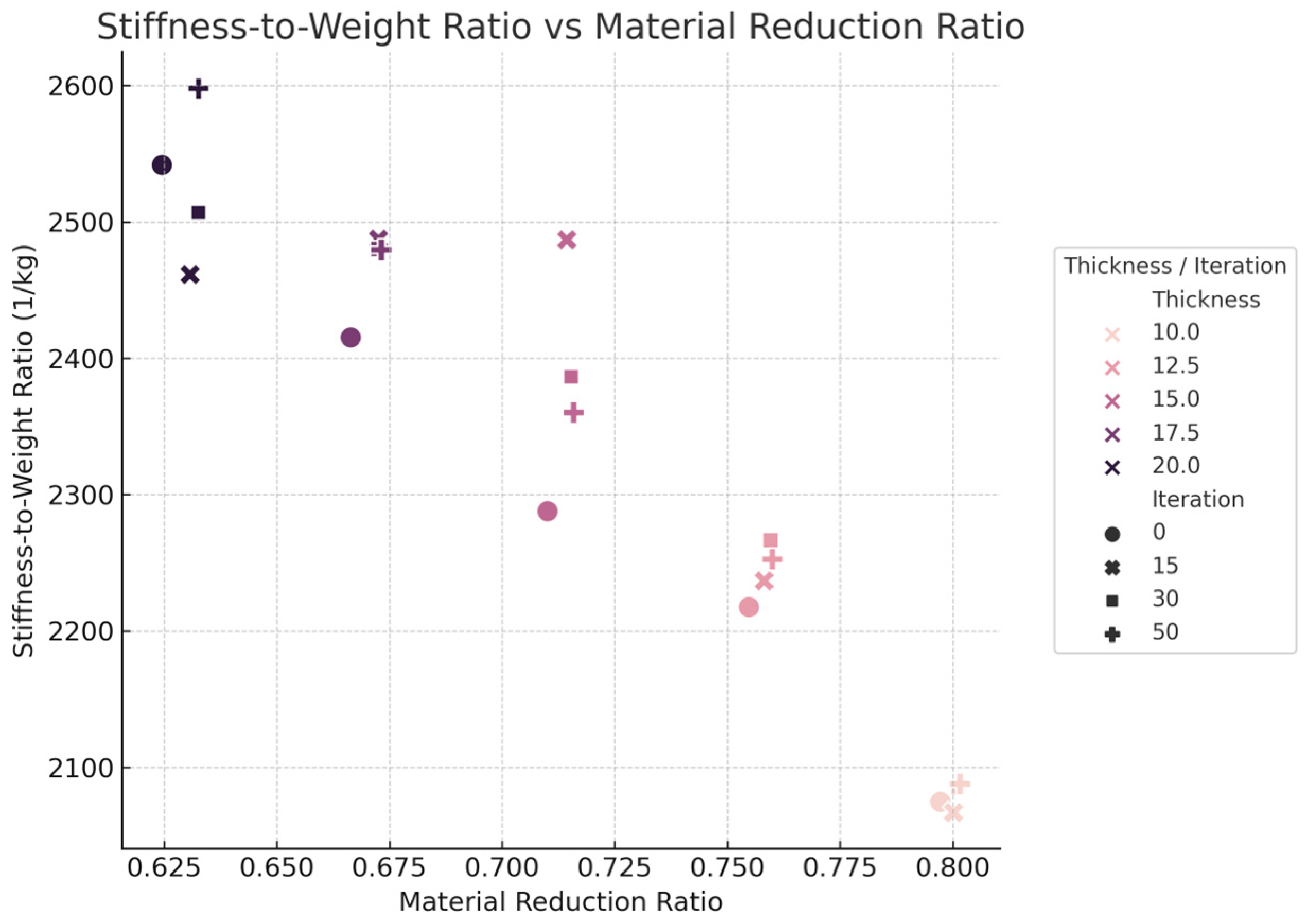
A strong positive correlation was observed between total volume reduction and the MRR, indicating that the adaptive Voronoi approach effectively minimizes material usage. Scatterplot analyses (
Figure 7) further suggested that configurations with 15 Lloyd iterations and beam sizes at 15 mm achieved a favorable balance between material efficiency and structural performance.
4.2. Stiffness-to-Weight Ratio (SWR) Performance
The SWR was used as a key indicator of structural efficiency. As shown in
Figure 8, this metric increased consistently with larger beam sizes and higher Lloyd iteration counts. The highest SWR of 2600 (1/kg) was obtained using a configuration that featured a beam size of 20 mm and employed 50 relaxation iterations, indicating superior load-bearing performance per unit weight.
Interestingly, several configurations in the mid-range thickness (15–17.5 mm, 15 iterations) displayed near-optimal SWR performance while using less material than the thickest variant. These findings underscore the importance of balancing member sizing and topological relaxation in achieving efficient structural systems.
4.3. Comparative Analysis with Existing Lightweight Structural Designs
To contextualize the performance of the proposed stress-responsive Voronoi shell structure, a quantitative comparison was conducted with several recent studies that reported stiffness-to-weight ratio (SWR) or equivalent specific stiffness enhancements through topology optimization, material grading, or geometry-material co-design strategies.
Garcia-Granada et al. [
27] implemented a topology optimization approach on FDM-printed ABS beams and achieved a 27.04% experimental increase in SWR, with simulation predicting a 31.7% gain. This represents one of the earliest practical validations of optimization-enhanced stiffness-to-weight efficiency in additive manufacturing. Seyedkanani et al. [
28] introduced a Teaching–Learning-Based Optimization method based grading strategy for cellular beams fabricated via SLA. Their results demonstrated a normalized SWR improvement of approximately 1.6× over a uniform baseline, accompanied by a 182% increase in bending stiffness, emphasizing the benefits of relative density control. Estakhrian et al. [
29] developed “Isoflex” composite beams using a PLA and wood–fiber blend with symmetric cell architectures. Their design led to a 130% enhancement in specific EI, along with a 72% increase in flexural stiffness and 39% in strength compared to monomaterial PLA beams. Zhang et al. [
30] combined topology optimization and fiber path alignment in CFRP composites, reporting a specific stiffness (E/ρ) of approximately 5.2 × 10
7 m
2/s
2. This structure surpassed commercial Markforged printed composites and outperformed aerospace-grade aluminum in stiffness-to-weight performance, highlighting the exceptional efficiency achievable through directional reinforcement.
In contrast, the proposed Voronoi shell structure maintains a high SWR range of 2200–2600 even after a significant 79.7% reduction in material volume. While most prior studies focus on beam-scale or unit cell structures, this work extends optimization to a spatial shell system under architectural-scale loads. The structure retains more than 57% of its original global stiffness while keeping maximum von Mises stress below 20 MPa, fully within PETG’s safe stress range. These results confirm that the Voronoi-based multi-objective optimization strategy can compete with or exceed the efficiency of beam-level designs, especially in terms of material reduction and structural robustness.
4.4. Maximum Deformation (MD) Analysis
MD values were computed for each variant under identical loading and boundary conditions. As anticipated, lower beam thicknesses generally resulted in higher deformation, while configurations with increased thickness and higher Lloyd iterations exhibited improved stiffness and minimized deformation.
As shown in
Figure 9, the configuration with 10 mm thickness and 0 iterations showed the highest deformation (~0.019 m), whereas the thickest variant (20 mm, 50 iterations) demonstrated the least deformation (~0.0083 m). The trend of how MD changes with the number of iterations in the structural LR algorithm is relatively smooth, with small fluctuations in the data. This indicates that merely increasing or changing the iteration count of the LR algorithm does not have a clear correlation with reducing MD. In contrast, the line chart of MD with respect to beam thickness shows a similar decreasing trend across all sets of results, suggesting that as the beams become thicker, the overall MD of the structure decreases. There is a strong correlation between beam thickness and MD. Notably, configurations at 17.5 mm beam thickness and 15 to 30 iterations yielded deformation values below 0.01 m, indicating that substantial structural rigidity can be achieved without resorting to maximum material usage.
4.5. Von Mises Stress Distribution
Stress analysis confirmed that all optimized variants remained within the allowable stress limits for PETG material (tensile yield strength: 53 MPa). However, configurations with thin members (<12.5 mm) and low relaxation counts exhibited higher peak stresses.
As shown in
Figure 10, the highest von Mises stress (~27.4 MPa) was observed in the 15 mm, 15-iteration case, concentrated near nodal joints with sharp topological transitions. By contrast, configurations with thicker beams and higher Lloyd relaxation iterations distributed stress more uniformly, reducing localized stress concentrations and enhancing safety margins.
4.6. Comparison to the Baseline Shell Structure
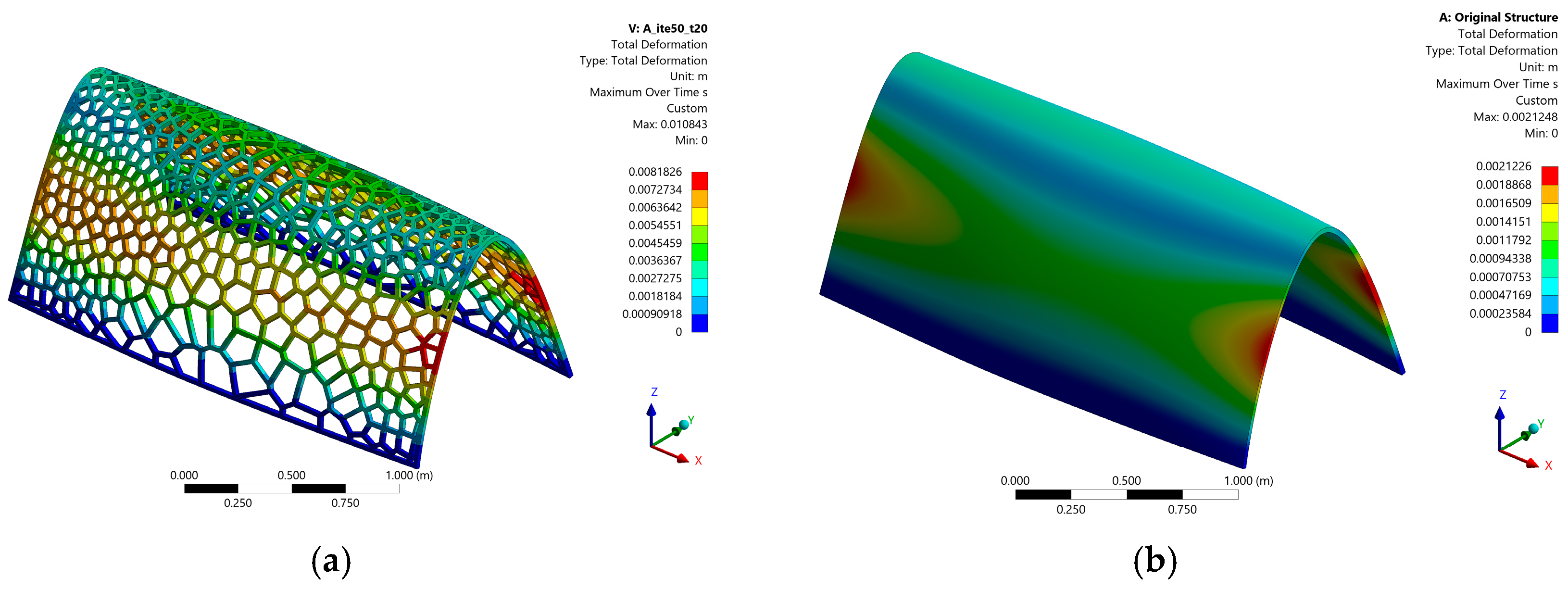
After analyzing the experimental data, the selected FEA data with structural significance will be compared, as shown in
Figure 11, with the FEA data of the baseline shell. The selected experimental variants for comparison are as follows:
The variant with the highest SWR (A_ite50_t20);
The variant with the minimum MD (A_ite50_t20);
The variant with the highest MRR (A_ite50_t10).
Figure 11.
Baseline Shell Comparison Example. (a) A_ite50_t20 FEA MD Result; (b) Original FEA MD Result.
Figure 11.
Baseline Shell Comparison Example. (a) A_ite50_t20 FEA MD Result; (b) Original FEA MD Result.
The data comparison is presented in
Table 2. In a multi-criteria evaluation system, it is common for two indicators to exhibit a negative correlation. In this case, the MRR and SWR are negatively correlated. This means that during the optimization process, if no common optimal solution exists, a trade-off must be made between these two evaluation indicators.
Furthermore, the variants used for comparison show significantly different structural volumes. This discrepancy complicates drawing direct conclusions from the analysis, even though multiple performance metrics are tested under the same conditions. This suggests that a new evaluation system may be required to more accurately assess whether the structure has been optimized relative to the original design and whether performance improvements have been achieved.
4.7. Performance Retention Under Consistent Load Conditions
All simulations were conducted under identical loading and boundary conditions, enabling a fair comparison across all variants. Despite significant material reductions observed in many optimized configurations, the resulting decline in structural performance was relatively modest. This highlights the effectiveness of the Voronoi-based optimization framework in preserving essential mechanical characteristics.
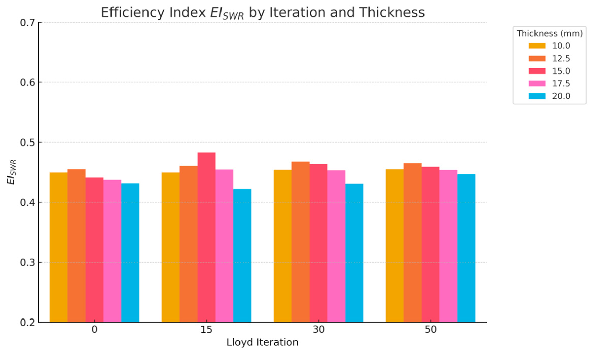
To quantify this relationship, we introduce a structural efficiency index (EI) defined as the ratio of material reduction to stiffness-to-weight performance loss:
where
is the material reduction ratio, and
refers to the stiffness-to-weight ratio. High
values indicate configurations that save significant material while maintaining a large proportion of the original structure’s stiffness efficiency.
As shown in
Figure 12, a bar chart was produced comparing all configurations using the baseline shell structure as a performance guideline. Variants with 15 iterations and 17.5 mm beam thickness exhibited the highest efficiency, suggesting that a significant portion of material could be eliminated while retaining 60–70% of structural stiffness.
In each iteration group, the EI for different beam thicknesses shows a similar trend: when the beam thickness is lower, its EI tends to be higher within the group. This phenomenon may indicate that the overall structural efficiency is higher when the beam thickness is between 10 mm and 15 mm.
This index provides a useful quantitative basis for evaluating the optimization “value” of different variants and may guide future studies on structurally efficient form-finding.
5. Discussion
This study presents a multi-scale computational framework integrating stress-informed TO, adaptive Voronoi tessellation, and a bi-objective GA for the design of lightweight architectural shell structures. By operating across macro-, meso-, and micro-scales, the proposed method achieves a balance between structural efficiency, material economy, and formal aesthetics. Simulation results demonstrate significant reductions in structural weight and deformation while maintaining stress levels well within material safety limits. These findings validate the effectiveness of the proposed approach and highlight its potential for real-world architectural applications.
Despite these promising results, several limitations and opportunities for further research remain. This section discusses the broader implications of the proposed method and outlines key directions for future investigations.
5.1. Structural Performance Under Complex Load Conditions
The current study focuses on simplified regular static loading scenarios involving dead, live, and wind loads. In real-world applications, structures often encounter dynamic, asymmetric, or time-dependent forces such as seismic actions or gust-induced loads. Future work could explore the response of stress-responsive Voronoi structures under more complex and realistic loading conditions, including dynamic and transient simulations, to assess their resilience and adaptive potential in extreme environments.
5.2. Multi-Material and Functionally Graded Design
This study utilizes a single material (PETG) for the entire structure. However, actual architectural systems may benefit from hybrid or composite materials to optimize performance across different regions of the structure. Subsequent studies may investigate the integration of functionally graded materials or multi-material strategies within the Voronoi framework, allowing spatially differentiated stiffness, density, or thermal properties to meet diverse functional and environmental demands.
Although PETG was specifically selected to illustrate manufacturability via additive fabrication technologies at a prototype scale, the optimization methodology itself remains largely material-agnostic. Future research could easily reparameterize the material properties within the same computational framework to explore alternative structural materials such as high-performance steel alloys, engineered timber, or hybrid composites like carbon fiber-reinforced PETG, further expanding the versatility and applicability of the presented design optimization strategy.
Moreover, future research should also address the intrinsic anisotropy and inhomogeneity resulting from the FDM fabrication process. Comprehensive experimental characterization of FDM-printed materials in different build orientations would help refine computational models and provide more accurate structural predictions, enhancing the applicability of computationally optimized designs in practical additive manufacturing scenarios.
5.3. Optimization of Structural Joints and Connections
While the present framework emphasizes geometry and member dimensions, the structural integrity of any space frame system also depends critically on the design of joints and node connections. Future investigations could incorporate joint behavior into the optimization process, considering rigid, semi-rigid, and articulated connections. Parametric control of node geometry could further enhance performance and facilitate fabrication through modular or prefabricated construction methods.
5.4. High-Efficiency Multi-Scale Optimization Algorithms
The hierarchical optimization process described here, while effective, is computationally intensive. The optimization and validation processes presented in this study were, to some extent, constrained by computational capacity and structural complexity. Nevertheless, the work demonstrates the potential of a multi-scale, composite optimization approach. Future research could focus on improving algorithmic efficiency using surrogate modeling, parallel computing, or machine learning-driven heuristics. These enhancements could significantly accelerate the optimization process, especially for large-scale structures or real-time design iterations. Also, a full-scale GA controlled CP generation, yet not completely incorporated in this study, remains promising after certain further research on its generation algorithms.
6. Conclusions
This study systematically explored a computational framework integrating SIMP-based TO, adaptive Voronoi tessellation, bi-objective GA, and weighted LR, aiming to optimize lightweight architectural shell structures through stress-responsive spatial configurations. The proposed multi-scale optimization process effectively addresses structural efficiency, material utilization, and aesthetic qualities simultaneously, demonstrating substantial benefits over conventional homogeneous designs.
Quantitative analysis of structural performance across 20 optimized design variants, as indicated by the provided dataset, yields several critical insights:
Material Efficiency:
Optimized variants showed a significant reduction in total material usage compared to baseline designs. Notably, the variant with 10 mm thickness and 50 Lloyd iterations achieved the highest MRR (80.16%). However, excessive material reduction in certain cases led to increased maximum stress concentrations (19.11 MPa) and larger MD (18.57 mm), indicating limitations in structural reliability at minimal thicknesses.
Balance between Structural Rigidity and Weight:
Configurations with moderate beam thicknesses (e.g., 12.5–15 mm) consistently presented an optimal balance, significantly outperforming baseline structures. Particularly, the configuration with 12.5 mm thickness and zero Lloyd iterations achieved an EI of approximately 0.455, reflecting a favorable trade-off between substantial weight savings (75.5% material reduction) and retained stiffness (SWR = 2217). This highlights the effectiveness of the adaptive Voronoi optimization approach in maximizing structural performance per unit of material consumed.
Structural Safety and Reliability:
All optimized designs, despite material reductions, maintained MVM stress levels (below 20 MPa) safely within the PETG material’s allowable tensile yield strength (53 MPa). This suggests that optimized configurations not only offer efficiency in material usage but also ensure structural integrity under prescribed loading conditions.
Conclusively, the study confirms the practical viability and substantial benefits of stress-responsive Voronoi optimization in architectural applications. The presented computational methodology provides a powerful approach to achieving lightweight, mechanically efficient, and aesthetically expressive structural forms.
Future research directions, guided by these findings, include exploring multi-material optimization strategies, incorporating real-world manufacturing constraints, evaluating dynamic load responses, and integrating lifecycle sustainability assessments. These directions collectively contribute to advancing the frontier of computational architectural design towards more sustainable, intelligent, and structurally optimized built environments.


 ,
, 


