Article

Study on the Influence Factors of Surrounding Tunnel Longitudinal Deformation Caused by Pit Excavation Based on Nonlinear Pasternak Modeling

1
College of Transportation Engineering, Nanjing Tech University, Nanjing 211816, China
2
Yangzhou Survey Design Research Institute Co., Ltd., Yangzhou 225007, China
*
Author to whom correspondence should be addressed.
Buildings 2025, 15(9), 1504; https://doi.org/10.3390/buildings15091504
Submission received: 18 March 2025 / Revised: 17 April 2025 / Accepted: 24 April 2025 / Published: 29 April 2025
(This article belongs to the Topic Sustainable Building Materials)

Abstract

:
In practical engineering, it is often necessary to constructed deep pits next to tunnels. So it is crucial to evaluate surrounding tunnels deformation and stress to ensure their safe operation. Pasternak soil model that considers soil nonlinear is adopted to solve tunnel beam’s differential equation to obtain longitudinal tunnel deformation and stress. The rationality of considering soil nonlinear methods was verified by contrasting measured with calculated results. On this basis, a comparative study was conducted on the calculation and analysis of various influencing factors based on engineering examples. It shows that the longitudinal tunnel deformation reduces with increase of soil modulus, tunnel axis and pit long side angle, tunnel stiffness reduction coefficient, tunnel axis and pit center horizontal distance. When discrete length of tunnel is less than 5 m, calculated value of longitudinal tunnel deformation changes little with discrete length. When pit depth increases, maximum longitudinal tunnel deformation also increases gradually. When tunnel buried depth gradually increases in the range of 1.5~3.9 times pit depth, maximum longitudinal tunnel deformation reduction rate becomes small. Similar pro-jects construction methods can refer to the results, and it have certain practical application value of engineering.

1. Introduction

Due to the extensive development and construction of domestic urban subways, there have been many real estate developments along the line, resulting in a large number of excavation and construction of foundation pits spanning underground subway tunnels. With the gradual increase of construction near the subway, such as deep and large pit excavation. During pit excavation, earth unloading, waterfall, vibration, loading and other factors will make changes around the pit and changes in the stress field, thus causing support structure deformation. This deformation will make changes of the original stress field of the soil body, which in turn will have an impact on the deformation of the tunnel. Since most of the tunnels in today’s cities are adopted the shield method, and the tunnel structure is formed by assembling prefabricated tube pieces, the overall stiffness of the shield tunnel is low and there are many seams, so engineering accidents are prone to occur, such as deformation, tilting, bulging, settlement, cracking, misalignment, tension, and leaking, etc. During pit excavation in Taipei City, the surrounding subway tunnel experienced wall damage, resulting in significant economic losses [1]. There is a large-scale construction of building foundation pits around Ningbo Metro Line 1, which has caused significant displacement near the excavation face in the left tunnel, resulting in cracks and leakage in the left tunnel lining. Therefore, conducting study on stress, deformation, and subway tunnels influencing factors during pits excavation has significant practical engineering application value.
At present, scholars are conducting research on the pit excavation impact on surrounding tunnels at home and abroad [2,3,4,5,6,7,8,9]. The deformation of the tunnel can be effectively reduced by reinforcing the soil layer [10,11,12]. Zhang et al. [13,14,15,16,17,18,19,20] adopted analytical method to study the tunnels deformation caused by pit excavation, the tunnel is simplified as an Euler-Bernoulli beam and Winkle model is adopted, and excavation sidewall influence is ignored. Then tunnel additional stress under the combined action of pit bottom and side wall load was calculated, and longitudinal tunnel deformation was solved. The calculated results showed the measured values are consistent with the calculated values, but the influence of the supporting structure was not considered in the study, resulting in inconsistency. Attewell et al. [21] simplified the soil to Winkle model, used elastic foundation beams to simulate the tunnel, and the reasonableness of this method was calculated and verified. Zhou et al. [22] calculated and analyzed the additional stress distribution on the tunnel axis when the pit is irregularly shaped, and further calculated longitudinal tunnel deformation and internal force. Sun et al. [23] calculated and analyzed the adjacent tunnels longitudinal deformation caused by pit excavation when the pit is circular, and carried out comparative analyses between the calculation and measured results of centrifugal machine and rectangular excavation results are verified the method reasonableness and reliability. Cheng, Xu et al. [24,25] proposed a calculation method that considers the existing tunnels shear effect when the pit is excavated, and further develops the sensitivity study of its influencing factors. Wei et al. [26,27] for the shield tunnel shear misalignment phenomenon in practical engineering, proposed a longitudinal deformation calculation method, and their method can also calculate the related shield tunnel misalignment amount, inter-ring shear, inter-ring angle, etc. Zheng et al. [28] combined numerical simulation methods to propose a simplified semi-empirical method to calculate the deformation, and combined with the measured results of 14 projects, proposed relevant empirical method and verified the formulas rationality. Zhang et al. [29] studied the variation law of tunnels longitudinal deformation based on the results of centrifuge tests. According to the experimental results, the tunnels deformation caused by asymmetric excavation will increase, and its excavation impact will be more significant. Zheng et al. [30] explored the tunnel deformation law produced by different support structures in foundation pits. Ding et al. [31] analyzed the engineering measurement data and further proposed a method of linearly representing the deformation at tunnel certain positions using the soil horizontal. Huang et al. [32] analyzed the centrifuge tests results and found that the excavation pit displacement and the longitudinal tunnel displacement exhibited an exponential decay. Jiang et al. [33], Wei et al. [34] further studied the impact of excavation pit displacement by considering the “shading effect” of the pit support structure. Zhang et al. [35] proposed a calculation method for the impact of excavation on tunnel deformation based on the influence of precipitation during foundation pit construction. The soil model used Pasternak foundation, and the tunnel was simplified into an elastic beam. The method was validated with engineering measurement data. Liu et al. [36] focused on the impact of large underground basements in the silty clay area of Nanjing on surrounding subway tunnels. They spent four years on-site tracking and monitoring the changes in parameters such as horizontal underground continuous walls deflection, tunnel arches vertical deformation, arch lines horizontal displacement, angle of expansion at pipe joints, misalignment, tunnel roof surfaces vertical deformation, horizontal arch lines lateral deformation, diameter convergence evolution, analyzed their variation patterns.
The Winkle soil model is commonly used to simulation foundation. Individual springs are not correlated with each other, so soil continuity cannot be considered, resulting in a large deviation from the actual results of Winkle soil model. The Pasternak soil model springs can be connected through shear layer. Thus, the Pasternak soil model can reflect compressive and shear soil characteristics. Kerr soil model simulates soil by introducing a third parameter. However, the parameters involved in the Kerr model has three, it is rarely adopted for its complexity. Most of the existing research results use the Pasternak model to study tunnel deformation, so the model is suitable for the dynamic loading process. Based on the above analysis, the two-stage calculation method is currently widely used to study the deformation. Firstly, using the Mindlin solution to calculate the tunnel additional stress; Then, it is acted on the tunnel, which is simplified as a foundation beam. Finally, the longitudinal tunnel deformation is solved using foundation beam theory. According to the US Guidelines for Seismic Design of Oil and Gas Pipeline Systems, It should consider soil nonlinear to calculate the pipe-lines longitudinal deformation and stress. In order to apply the existing analytical solutions to carry out the research, this paper ignores the three dimensional influence of the soil, without considering the influence of tunnel shear and torsional deformation.
Therefore, this article considers soil nonlinear and simulates shield tunnel with Euler Bernoulli beams. The differential equation is solved using the difference method. The calculation values are verified by actual engineering measurement results to analyze nonlinear model rationality, and further research is carried out on the relevant influencing factors.

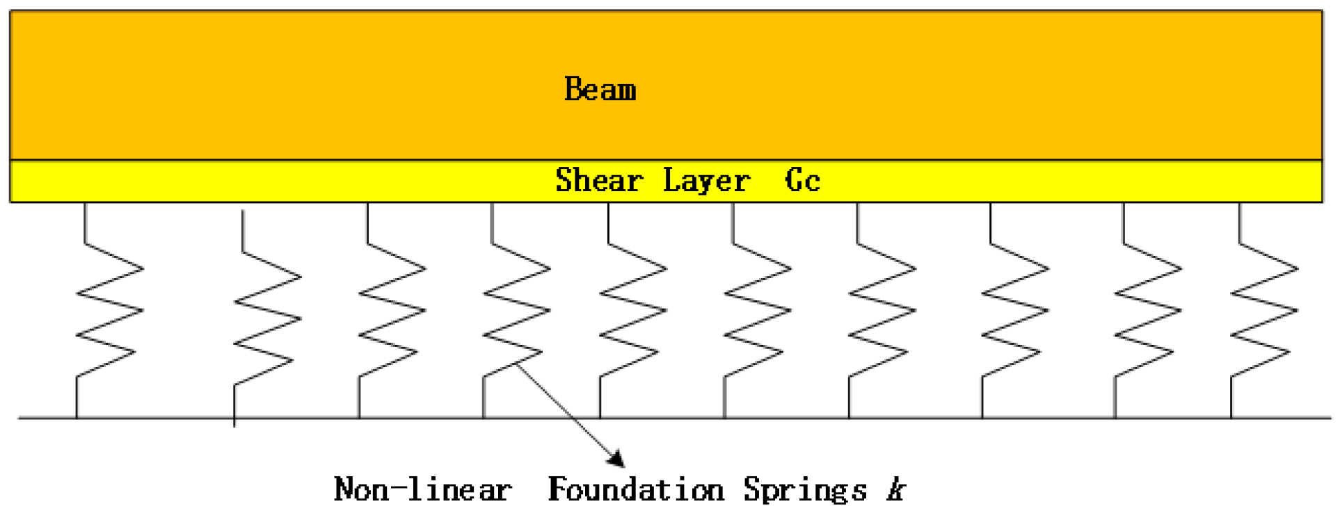
2. The Traditional Pasternak Foundation Model

The conventional Pasternak foundation model is shown in Figure 1 with its computational expression:
q ( x ) = k u ( x ) G c 𝜕 2 u ( x ) 𝜕 x 2
In the formula, q(x) is soil reaction force; u(x) is soil vertical displacement; k is foundation bed coefficient. Aettwell [37] provides an empirical calculation method for calculating k, see Equation (2):
k = 1.3 E s D 4 E I 1 12 E s D 1 v s 2
Gc is soil shear layer stiffness. Tanahashi [38] provides an empirical formula for calculating Gc. See Equation (3):
G c = E s h t 6 ( 1 + v )
where Es is the soil elasticity modulus, V is the Poisson’s ratio of the soil layer, and ht is the depth of the elastic layer, ht = 2.5D.
In general, soil has nonlinear characteristics. Therefore, Liang [39] studied the soil model in Figure 2. Soil reaction force is assumed to be related to its displacement. Other nonlinear influencing factors are not considered. The expression is:
q ( x ) = u ( x ) k 1 G c 𝜕 2 u ( x ) 𝜕 x 2
The specific parameters in Equation (4) are described in the literature [39,40].

3. Theory of Longitudinal Tunnel Deformation

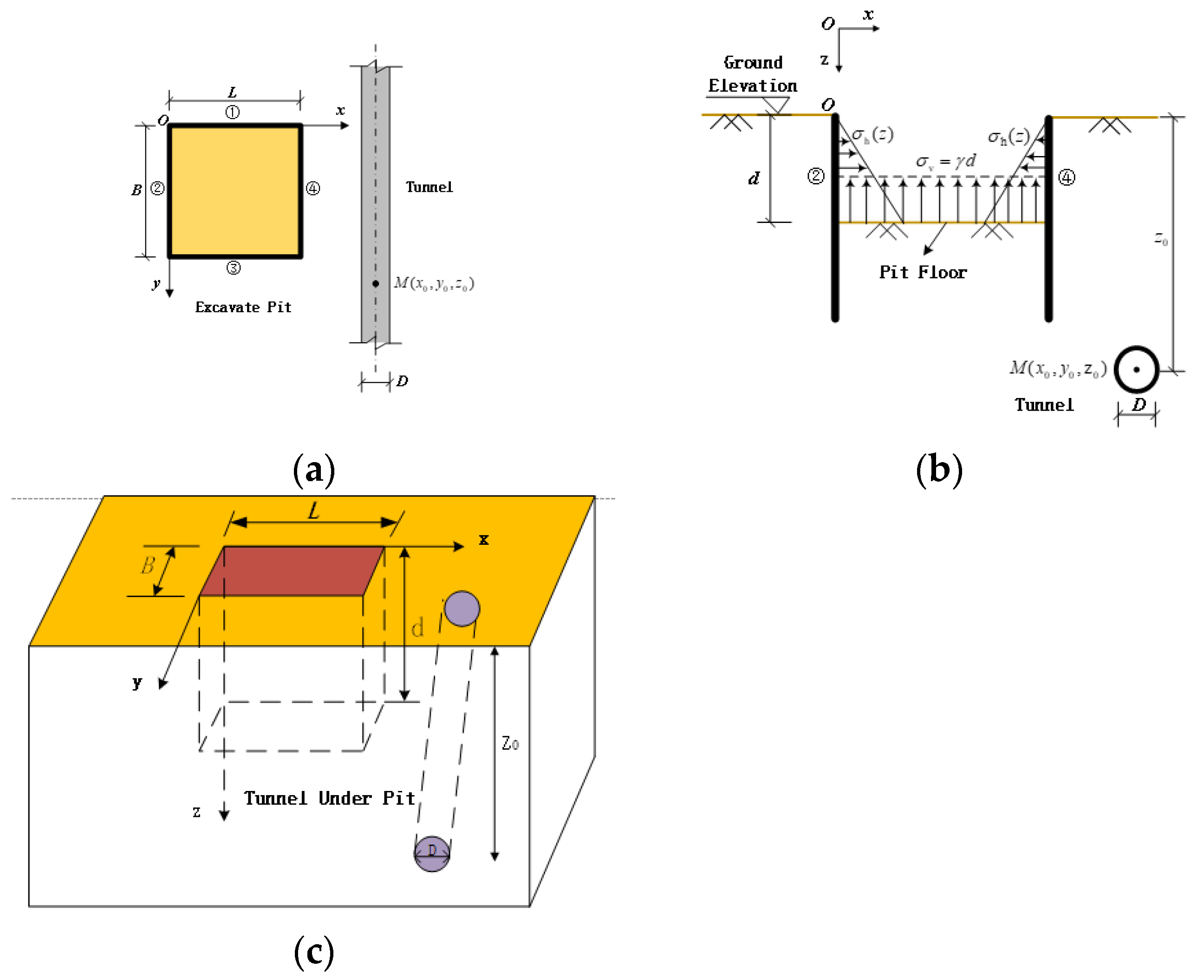
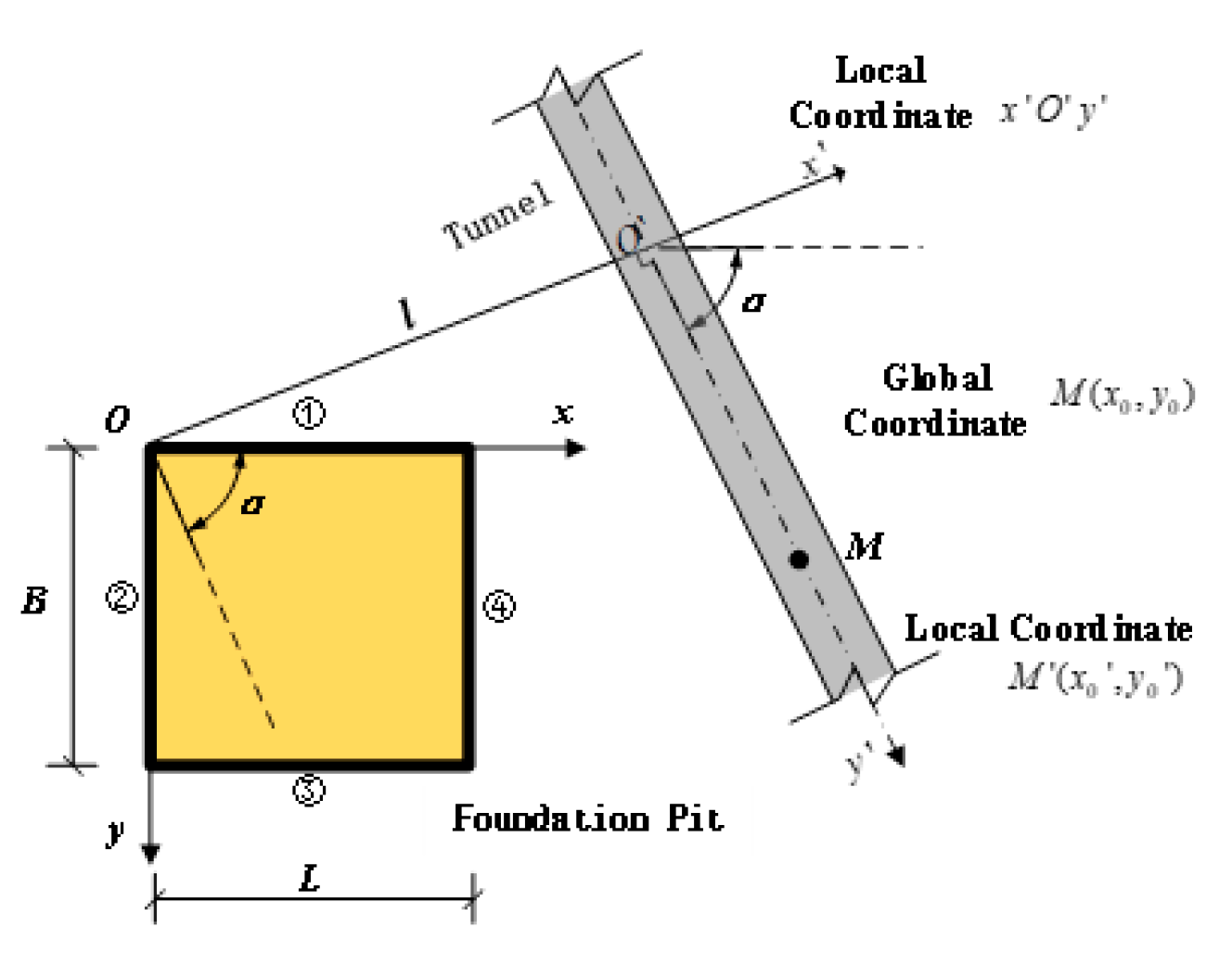
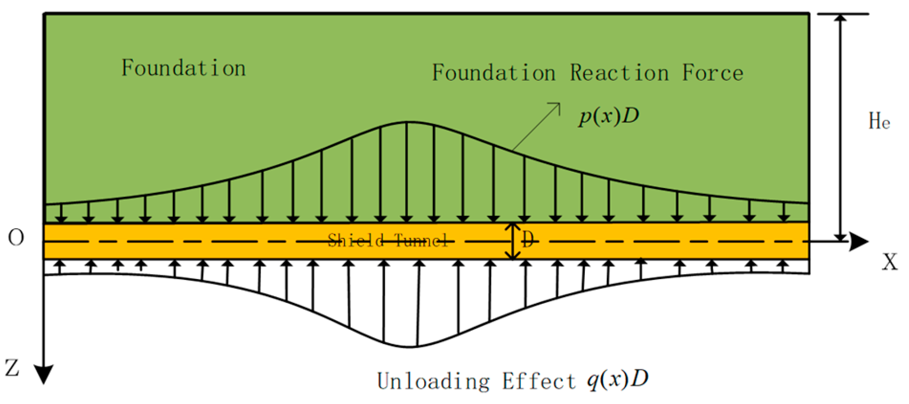
3.1. Tunnel Additional Stresses

From Figure 3 and Figure 4 shows that additional stresses generated by pit bottom and side wall. z0 is the buried depth, and soil any point is M(x0, y0, z0). Additional stresses can be calculated by Mindlin solution [41,42].
Calculation assumption: (1) It is assumed that tunnel is an beam of Euler Bernoulli; (2) It is assumed that the tunnel displacement is equal to soil; (3) It is assumed that pit excavation load is uniformly applied to bottom; (4) Mindlin solution is used assuming that there are no tunnels in soil; (5) Neglecting lateral friction resistance of pit support structure.

3.2. Tunnel Deformation Differential Equations

The foundation beam force analysis is seen in Figure 5, force analysis of beam element is seen in Figure 6.
The foundation beam deformation differential equations are Equation (5):
( E I ) e q d 4 u ( x ) d x 4 + ( u ( x ) k 1 G c 𝜕 2 u ( x ) 𝜕 x 2 ) D = p ( x ) D
The parameters in Equation (5) and specific formulas are given in the literature [39].

4. Solving Differential Equations for Tunnel Longitudinal Deformation

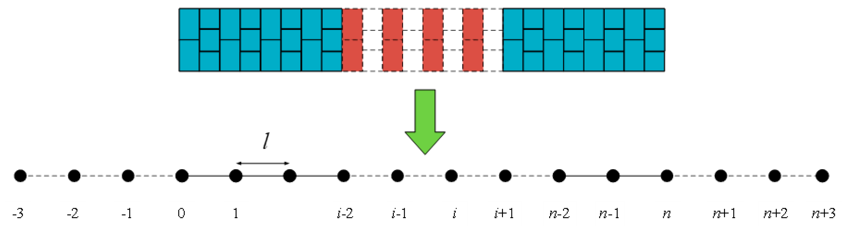
4.1. Finite Difference Format for Differential Equations

The seven-point Hermite interpolation method finite difference Format (6) was proposed in the literature [43]:
λ 1 u i 3 + λ 2 u i 2 + λ 3 u i 1 + λ 4 u i + λ 3 u i + 1 + λ 2 u i + 2 + λ 1 u i + 3 = p i
where λ i is the coefficient to be determined, i = 1 , 2 n . u i is the displacement at the node i. Equations (7)–(10) are obtained after computational derivation:
d 4 u ( x ) d x 4 = 0.2595 ( u i 3 + u i + 3 ) + 2.557 ( u i 2 + u i + 2 ) 7.8924 ( u i 1 + u i + 1 ) + 11.1899 u i l 4
d 3 u ( x ) d x 3 = 0.43255 ( u i 3 u i + 3 ) 0.1031 ( u i 2 u i + 2 ) + 1.50385 ( u i 1 u i + 1 ) l 3
d 2 u ( x ) d x 2 = 0.1 ( u i 2 u i + 2 ) + 1.4 ( u i 1 u i + 1 ) 2.6 u i l 2
d 2 q ( x ) d x 2 = 0.1 ( q i 2 q i + 2 ) + 1.4 ( q i 1 q i + 1 ) 2.6 q i l 2

4.2. Iterative Solution of Nonlinear Equations

Discretize the tunnel with a length of l and n+7 nodes, Six virtual nodes are assumed to exist at the end of the tunnel, they are −3, −2, −1, n+1, n+2, n+3. Tunnel is discretized in Figure 7, from which Equation (11) is derived.
( E I ) e q 11.1899 u i 7.8924 ( u i + 1 + u i 1 ) + 2.557 ( u i + 2 + u i 2 ) 0.2595 ( u i + 3 + u i 3 ) l 4 + u i D k 1 G c D 1.4 ( u i + 1 + u i 1 ) 0.1 ( u i + 2 + u i 2 ) 2.6 u i l 2 = p i D
In general, the impact on tunnels is limited. Therefore, selecting a sufficiently long tunnel and assuming bending moment, shear force, turning angle are equal to zero at both tunnel ends, then:
M 0 = ( E I ) e q d 2 u d x 2 = ( E I ) e q ( 2.6 u 0 + 1.4 ( u 1 + u 1 ) 0.1 ( u 2 + u 2 ) l 2 = 0 M n = ( E I ) e q d 2 u d x 2 = ( E I ) e q ( 2.6 u n + 1.4 ( u n 1 + u n + 1 ) 0.1 ( u n 2 + u n + 2 ) l 2 = 0
θ 0 = d u d x = u 1 u 1 2 l = 0 θ n = d u d x = u n + 1 u n 1 2 l = 0
Q 0 = ( E I ) e q d 3 u d x 3 = ( E I ) e q ( 0.43255 ( u 3 u 3 ) 0.1031 ( u 2 u 2 ) + 1.50385 ( u 1 u 1 ) l 3 ) Q n = ( E I ) e q d 3 u d x 3 = ( E I ) e q ( 0.43255 ( u n 3 u n + 3 ) 0.1031 ( u n 2 u n + 2 ) + 1.50385 ( u n 1 u n + 1 ) l 3 )
In Formulas (12)–(14), M0, θ0, and Q0 are the bending moment, rotation angle, and shear force at the node i = 0, respectively; Mn, θn, and Qn are the bending moment, rotation angle, and shear force at the node i = n; u3, u2, u-1, un+1, un+2, un+3 are −3, −2, −1, n+1, n+2, n+3 virtual node displacement.
Expression (15) can be obtained from the joint solution of Equations (12)–(14):
u 3 = 6.1972 u 0 6.6739 u 1 + 0.4767 u 2 + u 3 u 2 = 26 u 0 + 28 u 1 u 2 u 1 = u 1 u n + 1 = u n 1 u n + 2 = 26 u n + 28 u n 1 u n 2 u n + 3 = 6.1972 u n 6.6739 u n 1 + 0.4767 u n 2 + u n 3
Expanding Equation (11) yields n + 1 algebraic equation with matrix expression:
H t U + U Q D G U = P
where Ht is matrix of tunnel deformation; G is matrix of shear layer; W is vector of tunnel deformation; P is load vector; Q = 0.3 k u + U q u .
The virtual node Expression (13) is brought into Equation (14) to obtain each vector and matrix Expressions (17)–(20):
H t = ( E I ) e q l 4 56.9 57.5431 0.1237 0.519 1.1454 6.4809 7.6329 2.557 0.2595 2.557 8.1519 11.1899 7.8924 2.557 0.2595 0.2595 2.557 7.8924 11.1899 7.8924 2.557 0.2595 0.2595 2.557 7.8924 11.1899 7.8924 2.557 0.2595 0.2595 2.557 7.8924 11.1899 8.1519 2.557 0.2595 2.557 7.6329 6.4809 1.1454 0.519 0.1237 57.5431 56.9 ( n + 1 ) × ( n + 1 )
G = G c D l 2 0 0 0 0 0 1.4 2.7 1.4 0.1 0.1 1.4 2.6 1.4 0.1 0.1 1.4 2.6 1.4 0.1 0.1 1.4 2.7 1.4 0 0 0 0 0 ( n + 1 ) × ( n + 1 )
U = { u 0 , u 1 , u i , u i + 1 , , u n , u n + 1 } ( n + 1 ) T
P = D { p 0 , p 1 , p i , p i + 1 , , p n 1 , p n } ( n + 1 ) T
Such that:
K ( U ) = H t U + U Q D G U P
Then, the K(u) Jacobi matrix is:
K ( U ) = H t + H s G
where
K s = f 0 0 f 1 f i f n 1 0 f n ( n + 1 ) × ( n + 1 )
f i = ( u i D 0.3 k u + u i q u ) ' = 1 0.3 k u + u i q u D u i q u ( 0.3 k u + u i q u ) 2 D , ( i = 0 , 1 , 2 , n )
Then:
u ( k + 1 ) = u ( k ) ( K ' ( U ( k ) ) ) 1 K ( U ( k ) )
where k is the number of iterations; u(k) and u(k+1) is the tunnel longitudinal displacement vector at the k and k + 1 iterations.
Then, Newton’s iteration Formula (23) can be rewritten as (24) and Equation (25):
Δ u ( k ) = F ( u ( k ) ) 1 F ( u ( k ) )
u ( k + 1 ) = u ( k ) + u ( k )
Steps of nonlinear equations are as follows [44]:
(1)
Tunnel additional stress vector P is obtained from the Mindlin solution;
(2)
K(u) and K(u) are obtained according to Equations (21) and (22);
(3)
Determine the initial value u(0) according to the actual situation and use Formula (24) to compute u(k);
(4)
According to u(k) and Equation (25), it can compute u(k+1);
(5)
According to u(k+1) and Equation (24) obtained u(k+1); if u(k+1) < ε (ε is the calculation accuracy, generally assumed to be ε = 10−6), then u(k+1) is the final approximation result;
(6)
If u(k+1) > ε, Steps (4) and (5) are repeated until accuracy of solution is satisfied.
According to the analysis of the calculation process, it is generally possible to converge to longitudinal tunnel dis-placement solution that meets accuracy of required calculation after 10 iterations.

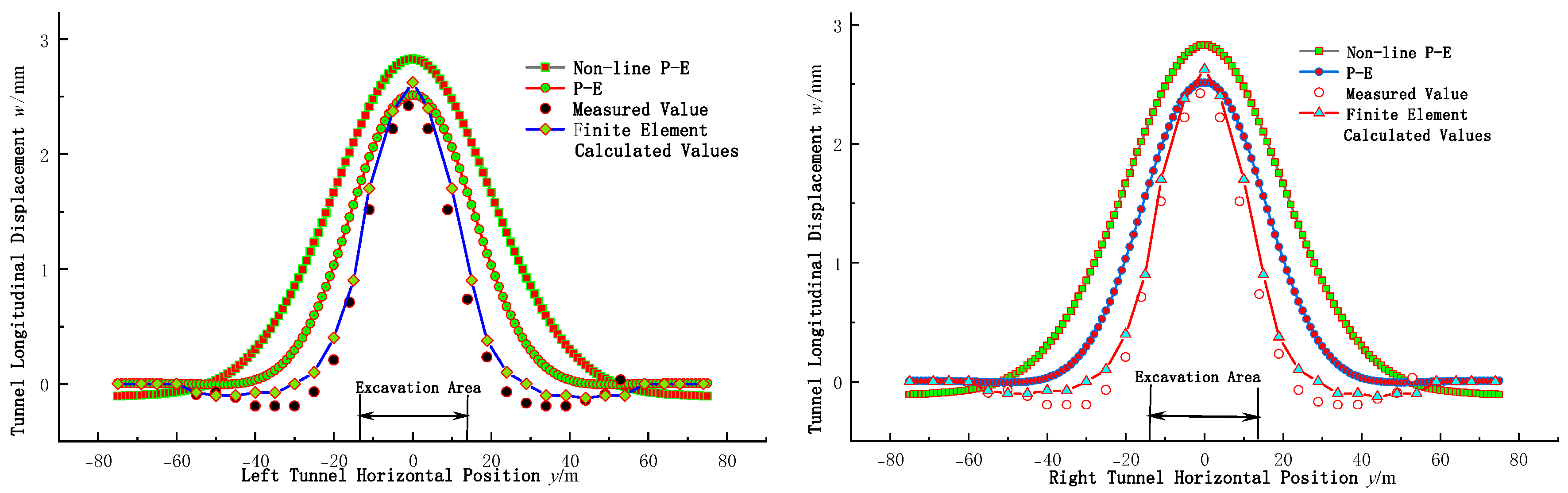
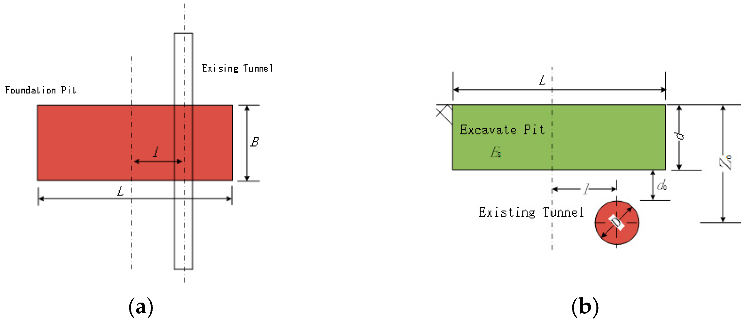
5. Engineering Case Study and Validation

The Nanjing Qingliangmen foundation pit project [45] involves the excavation of a subway tunnel beneath the foundation pit during construction.
This case is a deep pit above tunnel, and there are already two operating metro tunnels below the excavation pit. In order to make tunnel safe, the relevant units have made a comprehensive monitoring of the tunnel deformation, and obtained rich practical monitoring data, it is possible to compare calculated value with the measured. At the same time, the relevant researchers also adopted finite element numerical simulation calculations for this engineering case, and obtained the tunnel related deformation simulation data, which also provided detailed data for the analysis and calculation of this paper.
The excavation plan size L × B = 42 m × 28 m, pit depth d = 8.5 m, and foundation pit support structure consist of three supports. There is a pit above tunnel, with a burial depth z0 = 16.6 m, The top of the tunnel and pit bottom distance is 5 m, and tunnel outer diameter is 16.2 m. The axis lines of right and left rows of tunnels are 16.2 m apart. Table 1 are tunnel parameters, and the tunnel equivalent bending stiffness (EI)eq = 4.65 × 10⁵ MN.m2 is obtained by the method of Shiba [46].
In this paper, It is mainly focused on the influence of Nonlinear of the soil, and longitudinal tunnel stiffness is calculated mainly by Yukio Shina’s method. The influence of other factors is not considered. The engineering soil parameters are shown in Table 2.
Structure of tunnel is located in powdery clay. The foundation reaction coefficient and shear stiffness can be deter-mined from modulus of soil and soil Poisson’s ratio, so relevant parameters are obtained in Table 2,the relevant parameters are γ = 18.6 kN/m3, Es = 20.2 MPa, μ = 0.33, δu = 0.25 m, Ncv = 5.35, Su = 57 kPa.
The calculation displacement are seen in Figure 8. The nonlinear P-E in the figure represents foundation proposed in this paper using the nonlinear Pasternak model, and tunnel using the Euler Bernoulli beam calculation method; The P-E method adopts the traditional Pasternak foundation model, and the tunnel uses Euler Bernoulli beams. The measured values and finite element calculated values in Figure 8 can be found in reference [45].
From Figure 8, the longitudinal tunnel displacement trend obtained by three calculation methods is similar to values of measured, indicating that non-linear Pasternak calculation method used in the foundation model has certain rationality. According to the comparison of measured and calculated values, but there is a difference in the value, mainly because when pit is constructed, the soil will appear plastic deformation, the soil has nonlinear characteristics. In addition, ignoring existence of tunnels, soil parameters values, simplified Mindlin solutions will lead to anomalies between practical and theoretical values.
The maximum longitudinal tunnel displacement was generated at tunnel position directly below corresponding pit, and it is also the position with the highest additional stress in the tunnel. The measured maximum longitudinal deformation value of the tunnel left lane is 3.3 mm, and the measured maximum longitudinal deformation value of the tunnel right lane is 2.4 mm. Maximum longitudinal left tunnel deformation theoretical value based on soil nonlinearity is 3.5 mm, maximum of the right tunnel line is 2.8 mm. Maximum longitudinal left tunnel deformation based on P-E is 3.1 mm, Maximum longitudinal right tunnel deformation is 2.3 mm. Among three methods, maximum longitudinal tunnel deformation obtained by the nonlinear P-E method more in line with actual value. Analysis and method precision of this article and verification of other engineering cases can be found in the literature [47].

6. Parameter Impact Analysis

There are many factors that affect tunnels deformation, such as position of pit and tunnel, parameters of pit, parameters of tunnel, and soil parameters. This article adopts Pasternak soil model considering nonlinear to research influencing factors such as soil modulus Es, the length ln calculated by the difference method, tunnel and pit angle α, pit depth d, tunnel and pit horizontal distance l, burial depth of tunnel z0, and equivalent tunnel stiffness (EI)eq.
Explore the changing law of factors affecting the longitudinal tunnels deformation during foundation pits excavation, in order to better guide engineering design and construction.
The pit size is L × B = 40 m × 20 m, pit depth is d = 10 m. The pit is above tunnel, its short side parallels to tunnel axis. The tunnel burial depth is z0 = 17.1 m. The tunnel outer diameter D = 6.2 m. The pit bottom and tunnel top distance is 4 m. Tunnel equivalent bending stiffness (EI)eq = 7.8 × 10⁴ MN·m2. Foundation soil is considered homogeneous soil.
Soil parameters are μ = 0.35, γ = 18.5 kN/m3, Es = 10 MPa, δu = 0.26 m, Ncv = 5.5, Su = 29 kPa. The pit and tunnel location can be seen in Figure 9.

6.1. Influence of Soil Elastic Modulus

According to Figure 10, the variation of w and Es can be seen. In Figure 11 umax at different Es can be seen, with the horizontal coordinate being ratio of z0 to d, and the vertical coordinate being the maximum longitudinal tunnel deformation umax. From Figure 10, with foundation soil elastic modulus increases, longitudinal tunnels deformation range gradually decreases, value of longitudinal deformation also gradually decreases, indicating that influence on adjacent tunnels also decreases. From Figure 11, when soil Es increases to 30 MPa, maximum longitudinal tunnel deformation changes relatively little. From Figure 10 and Figure 11, when Es is 5 MPa, maximum longitudinal tunnel deformation is 14.1 mm. When Es is 40 MPa, maximum longitudinal displacement is 1.9 mm, which is 1/7 of the former. When excavating pit, increasing soil modulus can effectively reduce longitudinal deformation.

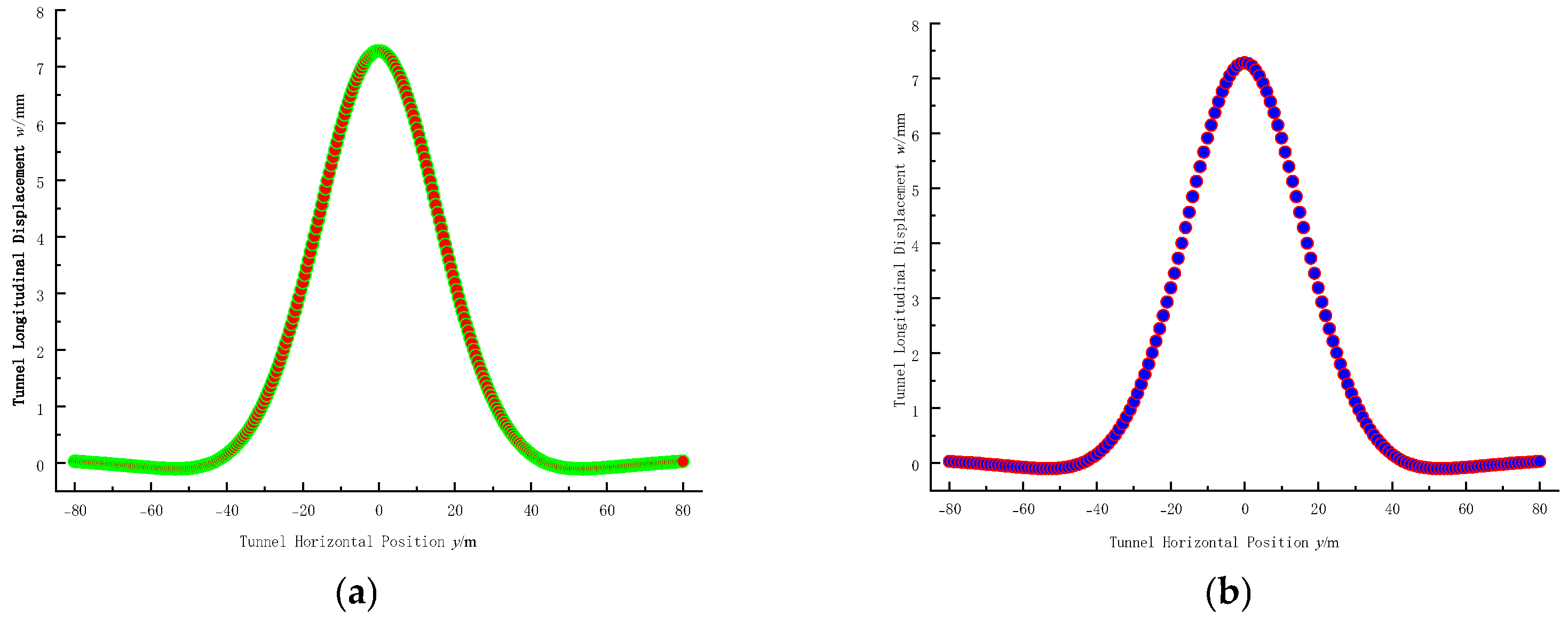
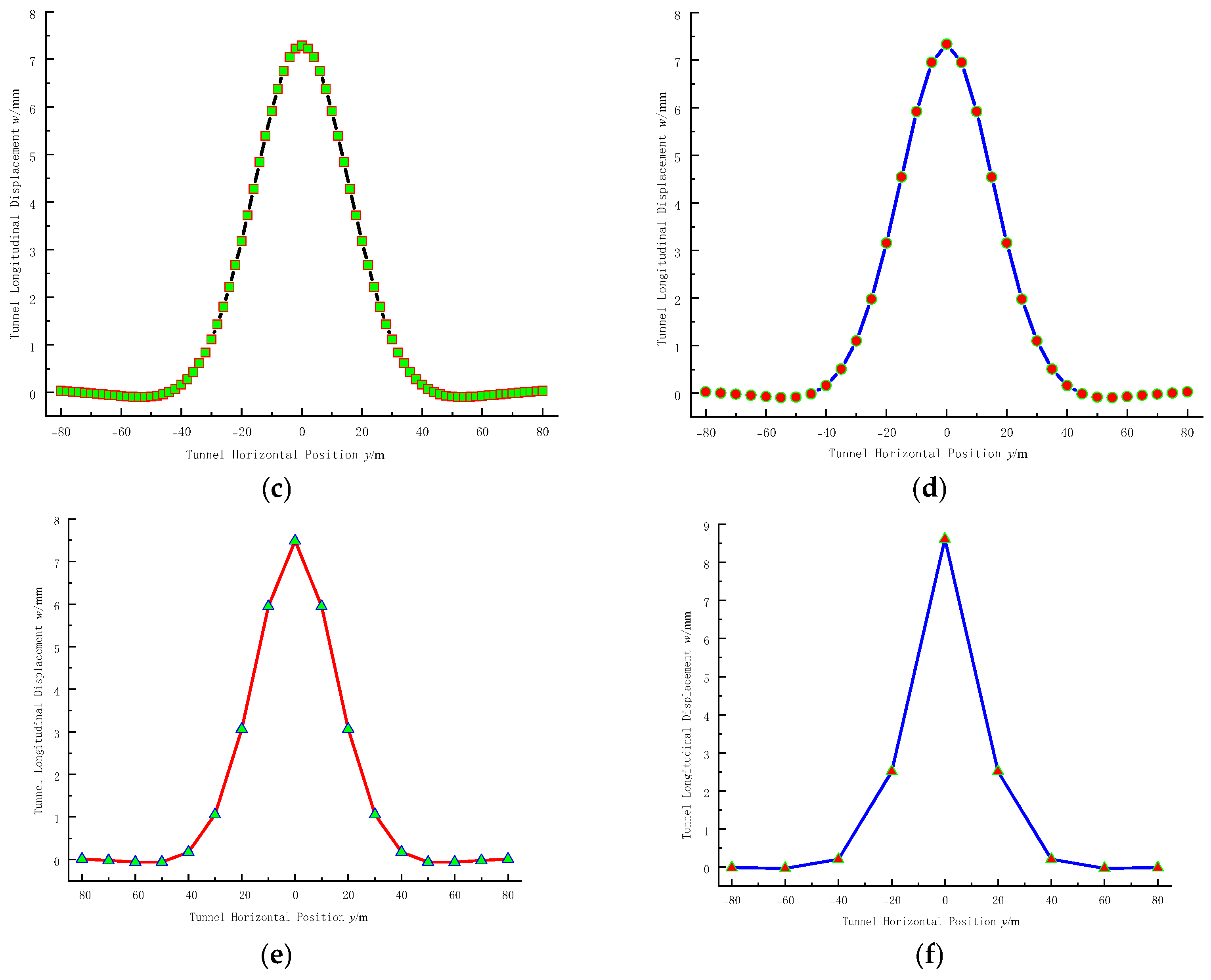
6.2. Effects of Differential Calculation Length

When using the difference method to compute deformation differential equation, it needs to takes the value for discrete tunnel length, that is the difference calculation length ln. Therefore, difference calculation length ln influence is analyzed.
Figure 12 shows the longitudinal tunnel deformation curves calculated using different differential lengths ln when the soil elastic modulus is 10 MPa and the calculated length of the tunnel is 160 m, where n is the number of calculation nodes.
From Figure 12, it can be seen that when the differential calculation length is less than 5 m, the calculated longitudinal tunnel deformation varies less with the differential length ln. When the difference calculation length is greater than 5 m, due to the selection of too few calculation points, the difference quotient cannot be used as an approximation of the derivative, resulting in a relatively large error in the difference calculation result. When the pit impact range is large, it can reduce the computational load, improve the calculation efficiency by appropriately increasing the length of the differential calculation, while also ensuring the calculation accuracy. Therefore, in the actual calculation process, the differential calculation length is generally taken as 1~5 m.

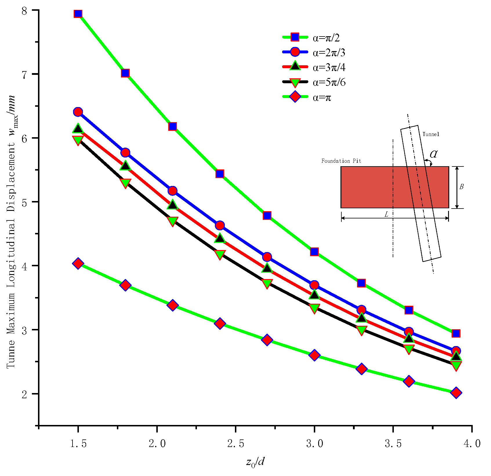
6.3. Influence of the Angle Between the Foundation Pit and the Tunnel

In practical engineering, pit side is diagonally crossed with tunnel axis, and there will be a certain angle α, which represents angle between the pit side and tunnel axis.
When angle α changes, longitudinal tunnel deformation will also change accordingly. In Figure 13, maximum longitudinal tunnel deformation umax varies when tunnel and pit angle α changes. The horizontal axis is ratio of burial depth of tunnel z0 to pit depth d, vertical axis is maximum longitudinal deformation of tunnel umax. The range of the angle α is π/2 to π, and the tunnel burial depth variation range is 1.5 to 4 times pit depth. From Figure 13, the larger the pit long side and tunnel axis angle α, the smaller longitudinal deformation of tunnel when z0/d is fixed.
Keeping the angle α constant, when ratio of burial depth of tunnel z0 to pit excavation depth d increases, maximum longitudinal deformation of tunnel umax decreases, decrease rate reduces accordingly. When the angle α=π/2 and burial depth of tunnel z0 is from 1.5d to 4d, maximum longitudinal displacement of tunnel umax decreases from 7.9 mm to 2.9 mm, which is 5 mm; When the angle α=π, umax decreases from 4.1 mm to 2.1 mm, which is 2 mm. From this, the larger long side of pit and tunnel axis angle α, the smaller impact on tunnel.

6.4. Impact of Excavation Depth on the Foundation Pit

Figure 14 shows influence of different depths of pit on longitudinal deformation of tunnel when burial depth of tunnel is z0 = 17.1 m. with pit depth increasing, maximum tunnel longitudinal deformation increases rapidly. When pit depth is 1~10 m, maximum tunnel longitudinal deformation gradually increases, meanwhile increase rate gradually enlarges; When pit depth is greater than 10 m~12 m, approximately 0.6 to 0.7 times burial depth of tunnel. maximum tunnel longitudinal deformation gradually increases, but increase rate decreases. Analyzing reasons, as pit depth increases, tunnel top and pit bottom distance becomes smaller, impact of excavation on adjacent tunnels becomes greater, leading to a sharp increase in longitudinal tunnel deformation. Meanwhile, as shown in Figure 14, the longitudinal tunnel deformation and uplift range is approximately 40 m, longitudinal tunnel deformation range changes less with pit depth increase. From this, reducing pit depth and increasing distance pit bottom and tunnel top can effectively reduce longitudinal tunnel deformation and ensure its safety. Generally, it is required that pit depth should not be more than 0.6~0.7 times tunnel buried depth.

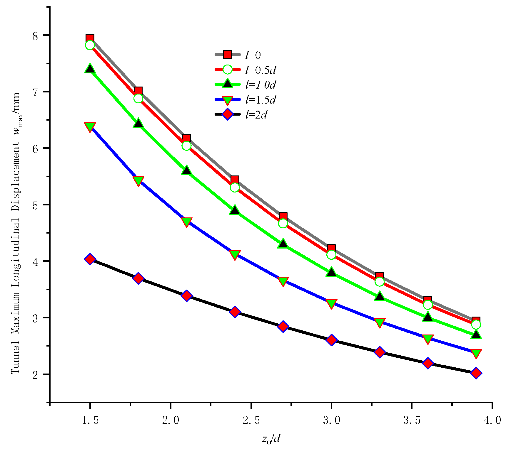
6.5. Influence of Tunnel and Pit Horizontal Distance

Figure 15 shows longitudinal tunnel deformation variation when pit center and tunnel axis horizontal distance changes. In Figure 15, when burial depth of tunnel is z0, as pit center and tunnel axis horizontal distance decreases, longitudinal deformation of tunnel increases, tunnel deformation length also increases. When horizontal distance is greater than 40 m, which is pit length, pit excavation impact is very small, which can be completely ignored. Therefore, when tunnel axis and pit center horizontal distance is less than pit length, it is necessary to consider pit impact on tunnel.
In Figure 16, maximum longitudinal deformation of tunnel at different pit and tunnel horizontal distances. Horizontal axis represents ratio of burial depth of tunnel z0 to the pit depth d, vertical axis represents umax. As can be seen from Figure 16. When pit and tunnel horizontal distance is determined, umax decreases approximately linearly with the tunnel depth z0. Meanwhile, as the horizontal distance increases, umax gradually decreases, and the rate of decrease also reduces. When the horizontal distance is greater than 1.5 times pit depth d, umax changes little with the variation of the burial depth z0. When the horizontal distance is equal to twice pit depth d, umax is 4 mm, which is half of 8 mm when l=0. From this, increasing the horizontal distance can effectively reduce the pit impact; When the horizontal distance remains constant, the greater tunnel burial depth, the less affecting on adjacent tunnels are by pit.

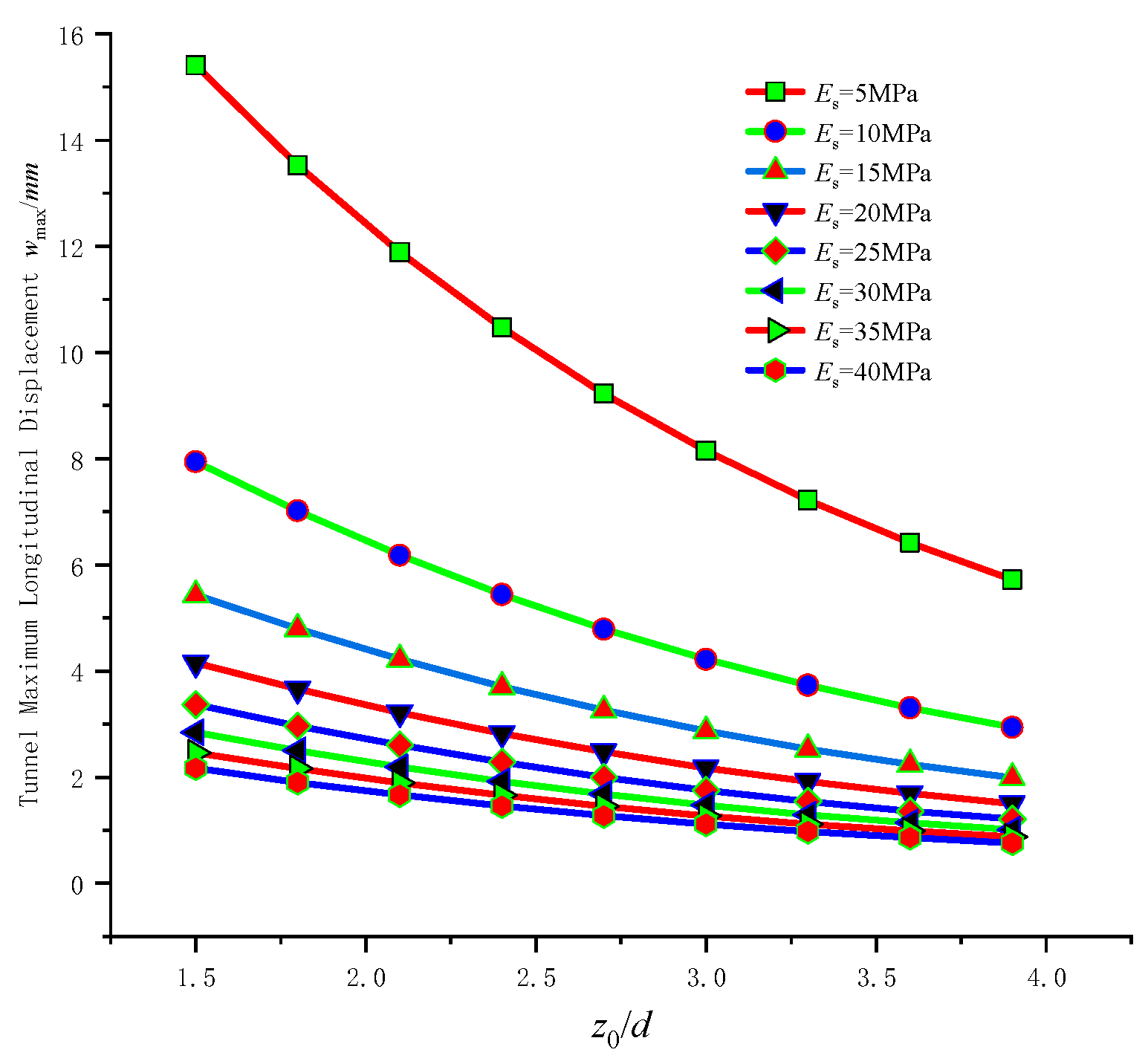
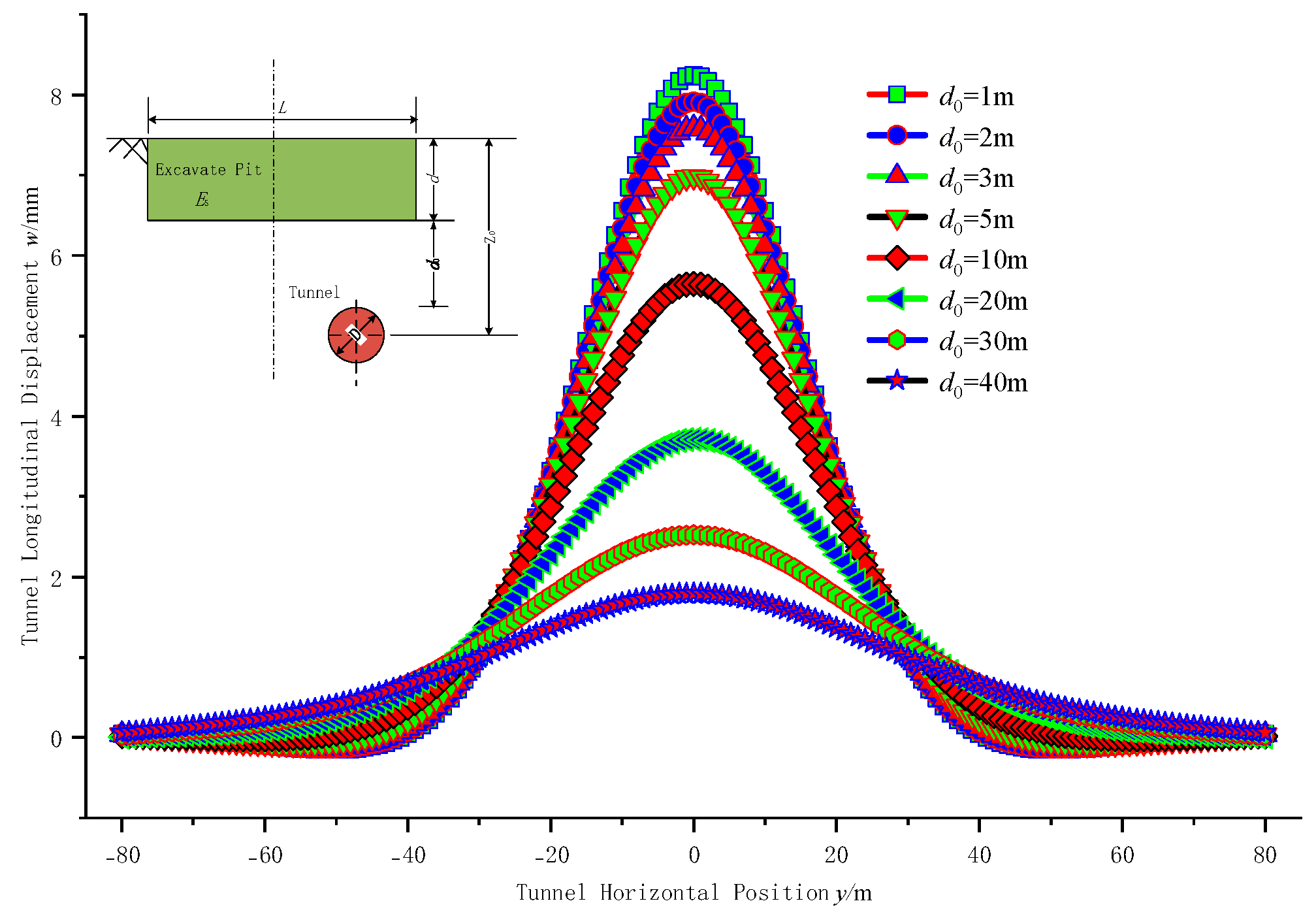
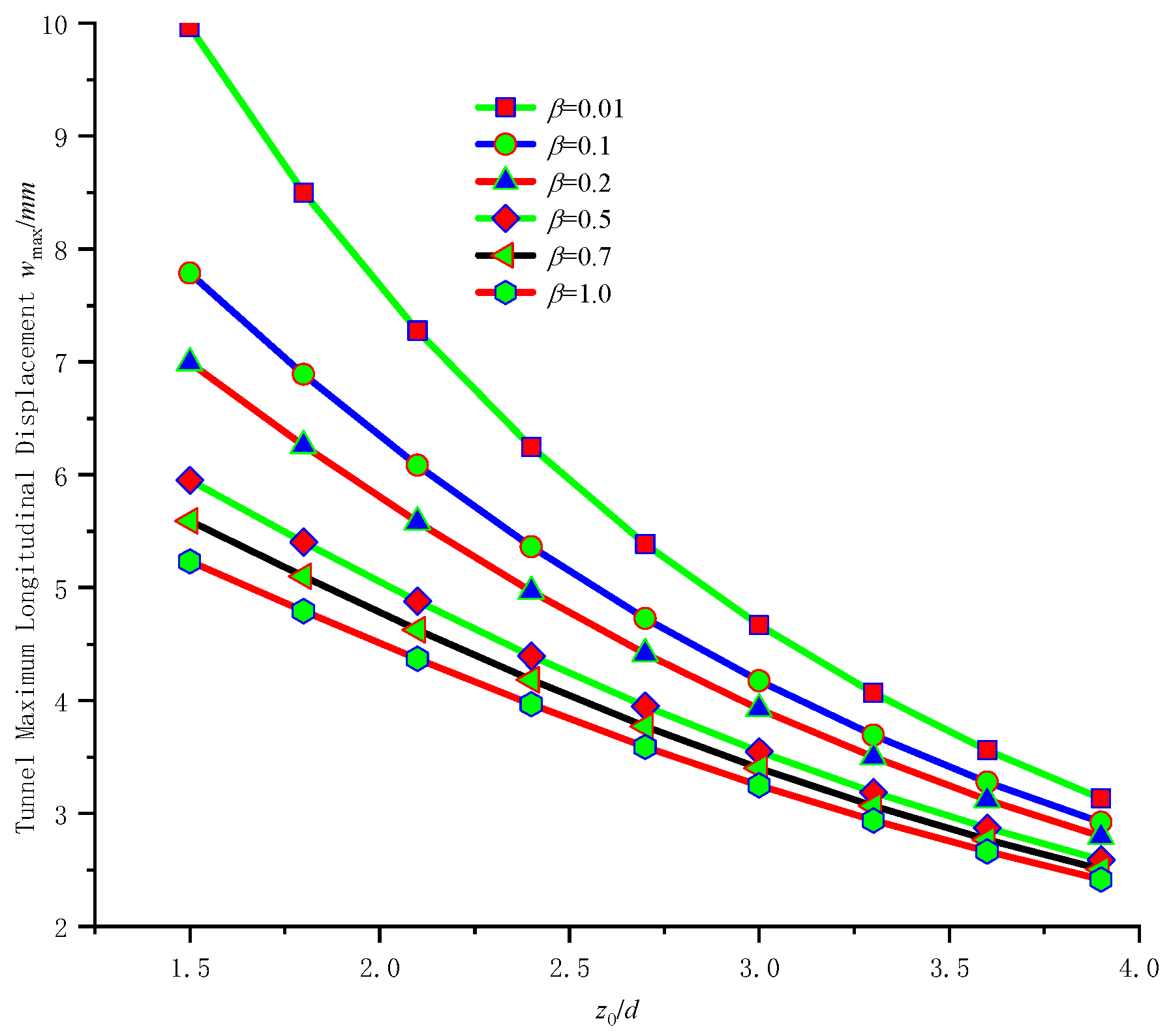
6.6. Impact of Tunnel Burial Depth

From Figure 17, tunnel deformation changes when burial depth z0 is different, where d0 is tunnel arch top and pit bottom net distance. When d0 = 1 m, maximum displacement umax is 8.2 mm. When d0 = 40 m, the maximum longitudinal tunnel displacement is umax = 1.8 mm. From this, the greater tunnel burial depth, the greater tunnel top and pit bottom distance, thus reducing pit impact. When tunnel is located below pit, i.e., d0 = 0, z0 is small, the tunnel will be greatly affected by pit excavation, produces large deformation. Therefore, when tunnel is directly below pit excavating, it need to monitor longitudinal tunnel deformation, monitor and evaluate the tunnel deformation in real time, and ensure the healthy and safe operation of the subway.
Figure 18 shows the maximum deformation umax with z0 changes. Horizontal axis represents ratio of horizontal tunnel and pit distance l to pit depth d, vertical axis represents umax. umax gradually decreases as l increases. Meanwhile, as z0 gradually increases, the umax decrease rate reduces. When z0 gradually increases, the tunnel and pit bottom distance gradually increases, pit impact gradually decreases. According to the calculation results, when z0 is more than 3.9 times d, umax is less than 1 mm, pit effect can be ignored.

6.7. Influence of the Equivalent Bending Stiffness of Tunnel

Shiba et al. [39] given a calculating tunnel equivalent bending stiffness (EI) eq method. However, shield tunnels are made up of concrete segments and bolted joints, and their cross-sectional bending stiffness is not the same as that of concrete as a whole. At this point, it needs to reduce tunnel bending stiffness. To reflect actual bending tunnel stiffness, reduction coefficient β is used, that is (EI) eq = βEcIc, where EcIc is the longitudinal bending stiffness of the cross-section of the concrete cast-in-place pipeline; β is the reduction coefficient of sectional bending stiffness, 0 < β ≤ 1. Assuming the diameter of the shield tunnel is 6.2 m, the thickness of the pipe segment is 0.35 m, the concrete of the pipe segment is Ec = 3.2 × 10⁴ MPa, and the moment of section inertia is Ic = 27.62 m3. The tunnel EcIc is 8.98 × 10⁵ MN·m2, and equivalent shield tunnel stiffness is (EI) eq = 7.8 × 10⁴ MN·m2, with β = 0.087.
Figure 19 shows the longitudinal shield tunnel deformation when β changes. From Figure 19, it can be seen that when β = 1, which means the tunnel is equivalent to a concrete pipeline, the longitudinal tunnel bending stiffness does not need to be reduced. At this time, the maximum tunnel bending stiffness is obtained, and the maximum longitudinal tunnel displacement umax obtained from this is 4.9 mm; When equivalent stiffness is taken by the Shiba method, that is, β = 0.087, the maximum longitudinal tunnel displacement umax is 7.3 mm; When the equivalent tunnel bending stiffness reduction coefficient is β = 0.01, umax is 8.9 mm. So when tunnel stiffness reduction coefficient decreases, longitudinal tunnel deformation gradually increases, and the pit impact becomes greater.
Figure 20 is maximum longitudinal tunnel deformation changing with tunnel stiffness reduction coefficient, horizontal axis is the ratio of z0 to d, vertical axis is umax. From Figure 20, when the equivalent tunnel stiffness reduction coefficient is small, pit excavation has an impact on the longitudinal deformation of shallow buried tunnels. Therefore, when the tunnel is buried at a z0,It should increase the tunnel’s bending stiffness and reduce its longitudinal deformation; When z0 is relatively large, pit bottom is far away from tunnel top, and pit impact on tunnel structure is small, So it can complies with tunnel safety standards requirements.

7. Conclusions

When computing pit impact on tunnels basis on soil nonlinearity, nonlinear Pasternak soil model was used. Additional load was obtained based on the Mindlin solution. Deformation differential equation was solved using Newton iteration method to solve. Calculation results were verified by actual measurement values. Furthermore, influence factors such as soil modulus, tunnel discrete length, pit long side and tunnel axis angle, tunnel axis and pit center horizontal distance, tunnel burial depth, tunnel stiffness reduction coefficient were further studied by combining engineering examples.
(1)
A nonlinear Pasternak soil model were used. Additional load obtained from Mindlin’s solution was adopted. Deformation differential equation was solved using Hermite interpolation and Newton method.
(2)
Based on actual pit engineering case, tunnel deformation was analyzed using Pasternak soil model considering soil non-linear. Calculation results were compared and analyzed with actual measurement data to expound rationality considering soil nonlinear.
(3)
The influence of relevant factors was explored using nonlinear Pasternak soil model. According to calculation results, longitudinal tunnel deformation decreases with increase of soil modulus, tunnel axis and pit long side angle, tunnel stiffness reduction coefficient, pit center and tunnel axis horizontal distance; When discrete length is less than 5 m, the calculated deformation varies less with discrete length; The maximum longitudinal tunnel deformation increases with pit depth increasing, and decreases with tunnel buried depth increasing.
Euler Bernoulli beam is used for calculation in this method, but tunnel shear deformation influence is not considered, Calculation of tunnel longitudinal stiffness does not take into account influence of lateral stiffness, so it should further study influencing factors in future research to improve calculation method. In addition, there are more nonlinear influencing factors of soil, and when using nonlinear Pasternak soil model, it is necessary to experimentally obtain the corresponding nonlinear parameters of different soils, which is a large amount of workload, and therefore will limit its ap-plication and popularization. In the future research, it should to further consider parameters acquisition method or relationship with other related parameters, so as to simplify the method of parameter value.

Author Contributions

Conceptualization, H.Z.; Software, Y.S.; Validation, H.Z.; Investigation, Y.S.; Data curation, H.Z.; Writing—original draft, H.Z.; Writing—review & editing, H.Z.; Project administration, H.Z.; Funding acquisition, H.Z. All authors have read and agreed to the published version of the manuscript.

Funding

This research received no external funding.

Data Availability Statement

The original contributions presented in this study are included in the article. Further inquiries can be directed to the corresponding author.

Conflicts of Interest

Author Yutao Song was employed by the company Yangzhou Survey Design Research Institute Co., Ltd. The remaining author declares that the research was conducted in the absence of any commercial or financial relationships that could be construed as a potential conflict of interest.

References

  1. Chang, C.-T.; Wang, M.J.; Chang, C.T.; Sun, C.W. Repair of displaced shield tunnel of the Taipei rapid transit system. Tunn. Undergr. Space Technol. 2001, 16, 163–173. [Google Scholar] [CrossRef]
  2. O’Rouke, T.D.; Ahmed, I. Effect of shallow trench construction on cast iron pipelines. In Advances in Underground Pipeline Engineering, Proceedings of the International Conference Sponsored by the Pipeline Division of the American Society of Civil Engineers; ASCE Press: New York, NY, USA, 1985. [Google Scholar]
  3. Lee, K.M. The effect of excavation for building on exiting underground tunnels. In Proceedings of the International Conference on Soft Soil Engineering—Recent Advances in Soft Soil Engineering, Guangzhou, China, 8–11 November 1993; Science Press: Beijing, China, 1993. [Google Scholar]
  4. Tang, M.X.; Zhao, X.H. Ground settlement and deformation calculation and application in deep excavation. J. Tongji Univ. Nat. Sci. 1996, 24, 238–244. [Google Scholar]
  5. Dolezalova, M. Tunnel complex unloaded by a deep excavation. Comput. Geotech. 2001, 28, 469–493. [Google Scholar] [CrossRef]
  6. Hu, Z.F.; Yue, Z.Q.; Zhou, J.; Tham, L.G. Design and construction of a deep excavation in soft soils adjacent to the Shanghai Metro tunnels. Can. Geotech. J. 2003, 40, 933–948. [Google Scholar] [CrossRef]
  7. Wang, W.D.; Wu, J.B.; Weng, Q.P. Numerical modeling of affection of foundation pit excavation on metro tunnel. Rock Soil Mech. 2004, 25 (Suppl. S2), 251–255. [Google Scholar]
  8. Li, J.P.; Ding, S.J. Influence of additional load caused by adjacent buildings on underground pipeline. J. Tongji Univ. Nat. Sci. 2004, 32, 1553–1557. [Google Scholar]
  9. Qi, K.J.; Wang, X.D.; Jiang, G.; Chang, Y.S.; Chen, Y.D. Analysis of deep pit excavation adjacent to tunnel. Chin. J. Rock Mech. Eng. 2005, 24, 5485–5489. [Google Scholar]
  10. Yuan, B.X.; Liang, J.K.; Zhang, B.F.; Chen, W.; Huang, X.; Huang, Q.; Li, Y.; Yuan, P. Optimized reinforcement of granite residual soil using a cement and alkaline solution: A coupling effect. J. Rock Mech. Geotech. Eng. 2025, 17, 509–523. [Google Scholar] [CrossRef]
  11. Yuan, B.X.; Liang, J.K.; Huang, X.L.; Huang, Q.; Zhang, B.; Yang, G.; Wang, Y.; Yuan, J.; Wang, H.; Yuan, P. Eco-efficient recycling of engineering muck for manufacturing low-carbon geopolymers assessed through LCA: Exploring the impact of synthesis conditions on performance. Acta Geotech. 2024. [Google Scholar] [CrossRef]
  12. Yuan, B.X.; Chen, W.J.; Li, Z.H.; Zhao, J.; Luo, Q.; Chen, W.; Chen, T. Sustainability of the polymer SH reinforced recycled Granite Residual Soil: Properties, physicochemical mechanism and applications. J. Soils Sediments 2023, 23, 246–262. [Google Scholar] [CrossRef]
  13. Zhang, Z.G.; Zhang, M.X.; Wang, W.D. Two-stage method for analyzing effects on adjacent metro tunnels due to foundation pit excavation. Rock Soil Mech. 2011, 32, 2085–2092. [Google Scholar]
  14. Zhang, Z.G.; Zhang, M.X.; Zhao, Q.H. A Simplified Analysis for Deformation Behavior of Buried Pipelines Considering Disturbance Effects of Underground Excavation in Soft Clays. Arab. J. Geosci. 2015, 8, 7771–7785. [Google Scholar] [CrossRef]
  15. Zhang, Z.G.; Huang, M.S.; Wang, W.D. Evaluation of Deformation Response for Adjacent Tunnels due to Soil Unloading in Excavation Engineering. Tunn. Undergr. Space Technol. 2013, 38, 244–253. [Google Scholar] [CrossRef]
  16. Zhang, Z.G.; Xu, C.; Gong, J.F. Influence of tunneling on deflection of adjacent piles considering shearing deformation of foundation and 3D effects of lateral soils beside piles. Chin. J. Geotech. Eng. 2016, 38, 846–856. [Google Scholar]
  17. Zhang, Z.G.; Wo, W.; Zhu, Z.G.; Han, K.H.; Sun, M.M. Fourier energy variational solution of effects on existing tunnels induced by shield tunneling considering coordinated deformation of lining cross-section. Rock Soil Mech. 2024, 45, 1397–1411+1422. [Google Scholar]
  18. Zhang, Z.G.; Cheng, Z.X.; Zhang, M.X.; Ma, S.K.; Lu, X.L. Dislocation Deformation of Existing Longitudinal Tunnel Structure Induced by Shield Tunneling by Under-crossing Considering Influence of Lining Permeability. China J. Highw. Transp. 2022, 35, 180–194. [Google Scholar]
  19. Zhang, Z.G.; Chen, Y.J.; Wei, G.; Ni, Y.; Li, J.J.; Shi, M.Z.; Mu, L.L. Time-Dependent Analysis of Deformation Induced by Soft Soil Pit Excavation Adjacent to Small Curvature Radius Tunnels. Available online: https://link.cnki.net/urlid/32.1124.TU.20241219.1554.002 (accessed on 20 December 2024).
  20. Zhang, Z.G.; Wei, J.; Mu, L.D.; Lü, X.; Ma, S.; Chen, Y.; Ni, Y.; Li, J. Time-dependent deformation analyses of existing tunnels due to curved foundation pit excavation applying fractional derivative Merchant model and irregular Timoshenko beam. Appl. Math. Model. 2025, 141, 115920. [Google Scholar] [CrossRef]
  21. Attewell, P.B.; Woodman, J.P. Predicting the Dynamics of Ground Settlement and its Derivatives Caused by Tunneling in Soil. Ground Eng. 1982, 15, 13–22, 36. [Google Scholar]
  22. Zhou, J.; Zhou, W.; Chen, B.Q. Calculation of Additional Stress of Metro Tunnel Caused by Adjacent Irregular Foundation Pit Excavation. J. Chongqing Jiaotong Univ. Nat. Sci. 2017, 36, 17–27. [Google Scholar]
  23. Sun, H.S.; Chen, Y.D.; Zhang, J.H.; Kuang, T. Analytical Investigation of Tunnel Deformation Caused by Circular Foundation Pit Excavation. Comput. Geotech. 2019, 106, 193–198. [Google Scholar] [CrossRef]
  24. Xu, R.Q.; Cheng, K.; Ying, H.W.; Lin, C.G.; Liang, R.Z.; Feng, S.Y. Deformation response of a tunnel under foundation pit unloading considering buried depth and shearing effect. Rock Soil Mech. 2020, 41 (Suppl. S1), 1–14. [Google Scholar]
  25. Cheng, K.; Xu, R.Q.; Ying, H.W.; Liang, R.Z.; Lin, C.G.; Gan, X.L. Simplified method for evaluating deformation responses of existing tunnel to overlying basement excavation. Chin. J. Rock Mech. 2020, 39, 637–648. [Google Scholar]
  26. Wei, G.; Zhang, X.H. Calculation of rotation and shearing dislocation deformation of underlying shield tunnels due to foundation pit excavation. J. Cent. South Univ. Sci. Technol. 2019, 50, 2273–2284. [Google Scholar]
  27. Wei, G.; Hong, W.Q.; Wei, X.J.; Zhang, X.; Luo, J.-W. Calculation of rigid body rotation and shearing dislocation deformation of adjacent shield tunnels due to excavation of foundation pits. Chin. J. Geotech. Eng. 2019, 41, 1251–1259. [Google Scholar]
  28. Zheng, G.; Yang, X.Y.; Zhou, H.Z.; Du, Y.; Sun, J.; Yu, X. A Simplified Prediction Method for Evaluating Tunnel Displacement Induced by Laterally Adjacent Excavations. Comput. Geotech. 2018, 95, 119–128. [Google Scholar] [CrossRef]
  29. Zhang, Y.W.; Xie, Y.L.; Weng, M.S. Centrifugal test on influence of asymmetric foundation excavation to an underlying subway tunnel. Rock Soil Mech. 2018, 39, 2555–2562. [Google Scholar]
  30. Zheng, G.; Du, Y.M.; Diao, Y.; Deng, X.; Zhang, L.M. Influenced zones for deformation of existing tunnels adjacent to excavations. Chin. J. Geotech. Eng. 2016, 38, 599–612. [Google Scholar]
  31. Ding, Z.; Zhang, X.; Jin, J.K.; Wang, L.Z. Measurement analysis on whole excavation of foundation pit and deformation of adjacent metro tunne. Rock Soil Mech. 2019, 40 (Suppl. S1), 415–423. [Google Scholar]
  32. Huang, X.; Huang, H.W.; Zhang, D.M. Centrifuge Modeling of Deep Excavation over Existing Tunnels. Proc. ICE-Geotech. Eng. 2014, 167, 3–18. [Google Scholar] [CrossRef]
  33. Jiang, Z.H.; Zhang, Y.X. Calculation of Influence on Longitudinal Deformation of Adjacent Tunnels Due to Excavation. J. Civ. Archit. Environ. Eng. 2013, 35, 7–11. [Google Scholar]
  34. Wei, G.; Zhao, C.L. Calculation method of additional load of adjacent metro tunnels due to foundation pit excavation. Ch:n. J. Rock Mech. Eng. 2016, S1, 3408–3417. [Google Scholar]
  35. Zhang, X.M.; Ou, X.F.; Yang, J.S.; Fu, J. Deformation Response of an Existing Tunnel to Upper Excavation of Foundation Pit and Associated Dewatering. Int. J. Geomech. 2017, 17, 04016112. [Google Scholar] [CrossRef]
  36. Liu, B.; Zhang, D.W.; Yang, C.; Zhang, Q.B. Long-term Performance of Metro Tunnels Induced by Adjacent Large Deep Excavation and Protective Measures in Nanjing Silty Clay. Tunn. Undergr. Space Technol. 2020, 95, 103147. [Google Scholar] [CrossRef]
  37. Aettwell, P.B.; Yeates, J.; Selby, A.R. Soil Movements Induced by Tunnelling and Their Effects on Pipelines and Structures; Blackie and Son Ltd.: London, UK, 1986; pp. 128–132. [Google Scholar]
  38. Tanahashi, H. Formulas for an infinitely long Bernoulli-Euler beam on the Pasternak model. Soils Found. 2004, 44, 109–118. [Google Scholar] [CrossRef]
  39. Liang, R.Z. Simplified analytical method for evaluating the effects of overcrossing tunnelling on existing shield tunnels using the nonlinear Pasternak foundation model. Soils Found. 2019, 59, 1711–1727. [Google Scholar] [CrossRef]
  40. ALA. Guidelines for the Design of Buried Steel Pipe; American Lifelines Alliance: Washington, DC, USA, 2005. [Google Scholar]
  41. Mindlin, R.D. Force at a point in the interior of a semi-infinite solid. J. Appl. Phys. 1936, 7, 195–202. [Google Scholar] [CrossRef]
  42. Meng, F.; Qiao, S.F. Study on the deformation of existing tunnel under the combined effect of pit excavation and dewatering based on the Kerr foundation model. Tunn. Undergr. Space Technol. 2025, 158, 106382. [Google Scholar] [CrossRef]
  43. Shen, G.Z.; Zhao, H.H.; Zhao, K.; Li, Y. Hermite Difference Method for Tunnel Longitudinal Displacement Caused by Deep Foundation Pit Excavation. Chin. J. Undergr. Space Eng. 2020, 16, 841–848. [Google Scholar]
  44. Kang, C.; Ye, C.; Liang, R.Z.; Sun, L.W.; Fang, Y.X.; Wu, W.B. Nonlinear longitudinal deformation of underlying shield tunnels induced by foundation excavation. Chin. J. Rock Mech. Eng. 2020, 39, 2341–2350. [Google Scholar]
  45. Cao, S.; Qian, D.L.; Wei, X.Y.; Cheng, H.; Ma, X.F. Influence of deep foundation pit excavation underlying metro tunnel and control measure. J. Hefei Univ. Technol. Sci. Technol. 2014, 37, 1479–1482+1536. [Google Scholar]
  46. Shiba, Y.; Kawashima, K.; Obinata, N.; Kano, T. Evaluation procedure for seismic stress developed in shield tunnels based on seismic deformation method. J. Jpn. Soc. Civ. Eng. 1989, 1989, 385–394. (In Japanese) [Google Scholar] [CrossRef] [PubMed]
  47. Zhao, H.H.; Song, Y.T. Study on longitudinal nonlinear deformation of adjacent existing tunnels induced by deep foundation excavation. Sci. Rep. 2025, 15, 9879. [Google Scholar] [CrossRef] [PubMed]
Figure 1. The Pasternak soil model.
Buildings 15 01504 g001
Figure 2. Schematic diagram of soil reaction forces and displacements.
Buildings 15 01504 g002
Figure 3. The relative positions of the pit and the tunnel. (a) Top view; (b) front view; (c) three-dimensional diagrams.
Buildings 15 01504 g003
Figure 4. Sketch diagram of the oblique intersection of the foundation pit and tunnel.
Buildings 15 01504 g004
Figure 5. Schematic of Pasternak foundation and foundation beam forces.
Buildings 15 01504 g005
Figure 6. Schematic diagram of micro segmented force on the foundation beam.
Buildings 15 01504 g006
Figure 7. Discrete treatment of tunnel.
Buildings 15 01504 g007
Figure 8. Contrast diagram of tunnel longitudinal displacement.
Buildings 15 01504 g008
Figure 9. Relative position of pit and tunnel. (a) Plan view; (b) sectional view.
Buildings 15 01504 g009
Figure 10. Longitudinal tunnel deformation under different soil modulus.
Buildings 15 01504 g010
Figure 11. Maximum longitudinal tunnel deformation under differentsoil modulus.
Buildings 15 01504 g011
Figure 12. Longitudinal deformation diagram of tunnel with different differential accuracy. (a) ln = 0.5 m, n = 321; (b) ln = 1 m, n = 161; (c) ln = 2 m, n = 81; (d) ln = 5 m, n = 33; (e) ln = 10 m, n = 17; (f) ln = 20 m, n = 9.
Buildings 15 01504 g012aBuildings 15 01504 g012b
Figure 13. Maximum longitudinal deformation of the tunnel at different angles with the foundation pit.
Buildings 15 01504 g013
Figure 14. Longitudinal deformation of the tunnel under different excavation depths.
Buildings 15 01504 g014
Figure 15. Longitudinal tunnel deformation with different pit and tunnel horizontal distance.
Buildings 15 01504 g015
Figure 16. Maximum longitudinal tunnel deformation with different pit and tunnel horizontal distance.
Buildings 15 01504 g016
Figure 17. Longitudinal deformation with tunnel buried depth changing.
Buildings 15 01504 g017
Figure 18. Maximum longitudinal deformation with tunnel buried depth changing.
Buildings 15 01504 g018
Figure 19. Tunnel longitudinal deformation with equivalent stiffness changes.
Buildings 15 01504 g019
Figure 20. Maximum tunnel deformation with equivalent stiffness changes.
Buildings 15 01504 g020
Table 1. Parameters of Tunnel.
Tunnel Outer Diameter D/mTunnel Internal Diameter/mTube Thickness t/mRing Width ls/mTube Sheet Elasticity Modulus Ec/MPaNumber of Bolts nLinear Stiffness of Bolted Joints kb/(MN/m)Inertia Moment of the Tunnel Section Ic/m4
6.25.50.351.53.25 × 10448014827.62
Table 2. Parameters of Soil.
Layer NumberSoil Layer NameThicknesses/mSoil Bulk Weight γ/(kN·m−3)Soil Elasticity Modulus Es/MPaPoisson’s Ratio μAngle of Internal Friction φ/(°)Cohesion c/kPa
1Miscellaneous Fillings3.218.624.00.39
2Plain Fill3.119.526.60.3614.123.7
3Soft Plastic Powdery Clay2.919.531.40.3616.122.1
4Powdery Clay11.618.620.20.3315.213.7
5Residual Soil5.720.535.60.3018.136.1
6Moderately Weathered Mudstone Sandstone26.523.550000.2030.0180.0
Disclaimer/Publisher’s Note: The statements, opinions and data contained in all publications are solely those of the individual author(s) and contributor(s) and not of MDPI and/or the editor(s). MDPI and/or the editor(s) disclaim responsibility for any injury to people or property resulting from any ideas, methods, instructions or products referred to in the content.

