
The HBIM Model as a Source in the Building Reconstruction Process: A Case Study of the “Koprówka” in Celestynów, Poland


Abstract
1. Introduction
2. Literature Review
3. Materials and Methods
4. Results
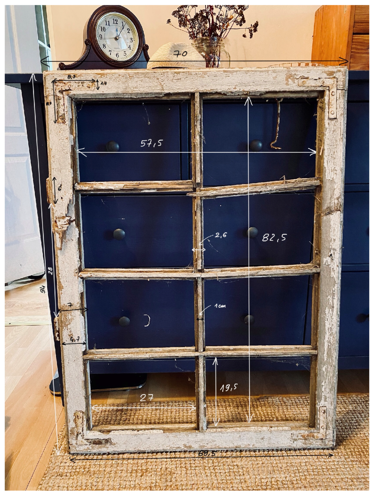
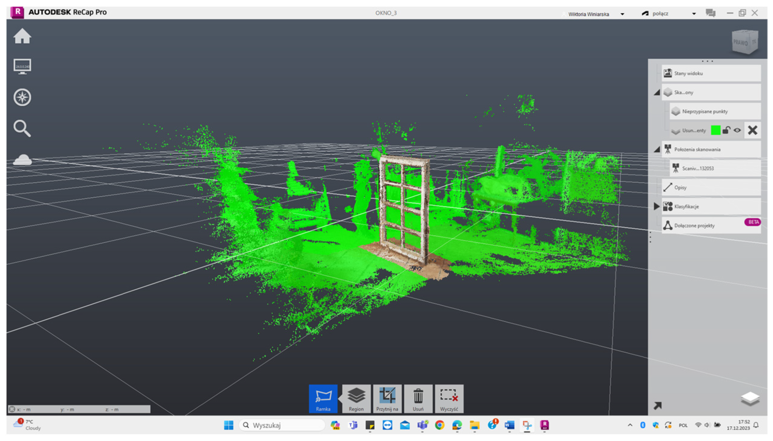
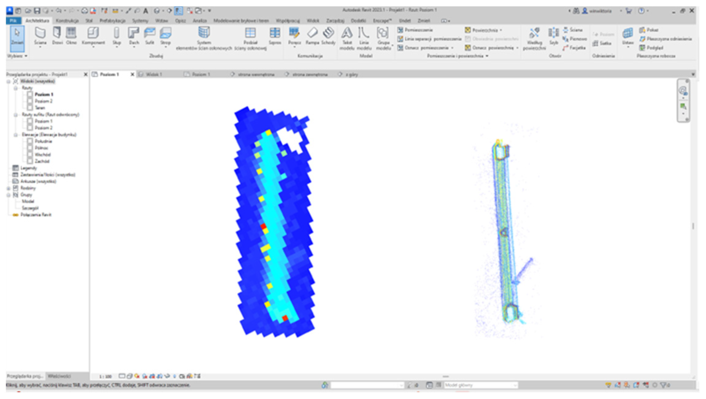
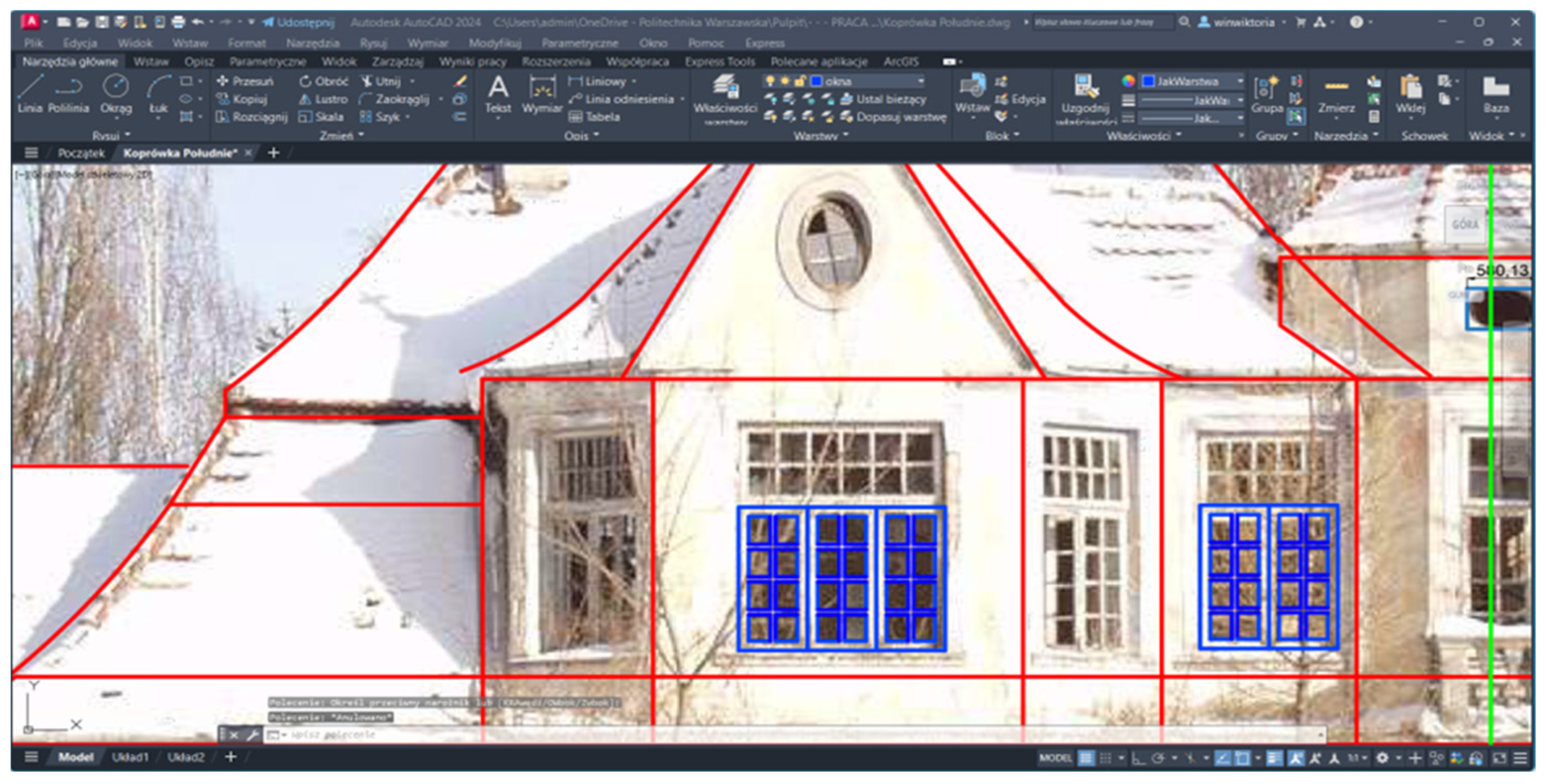
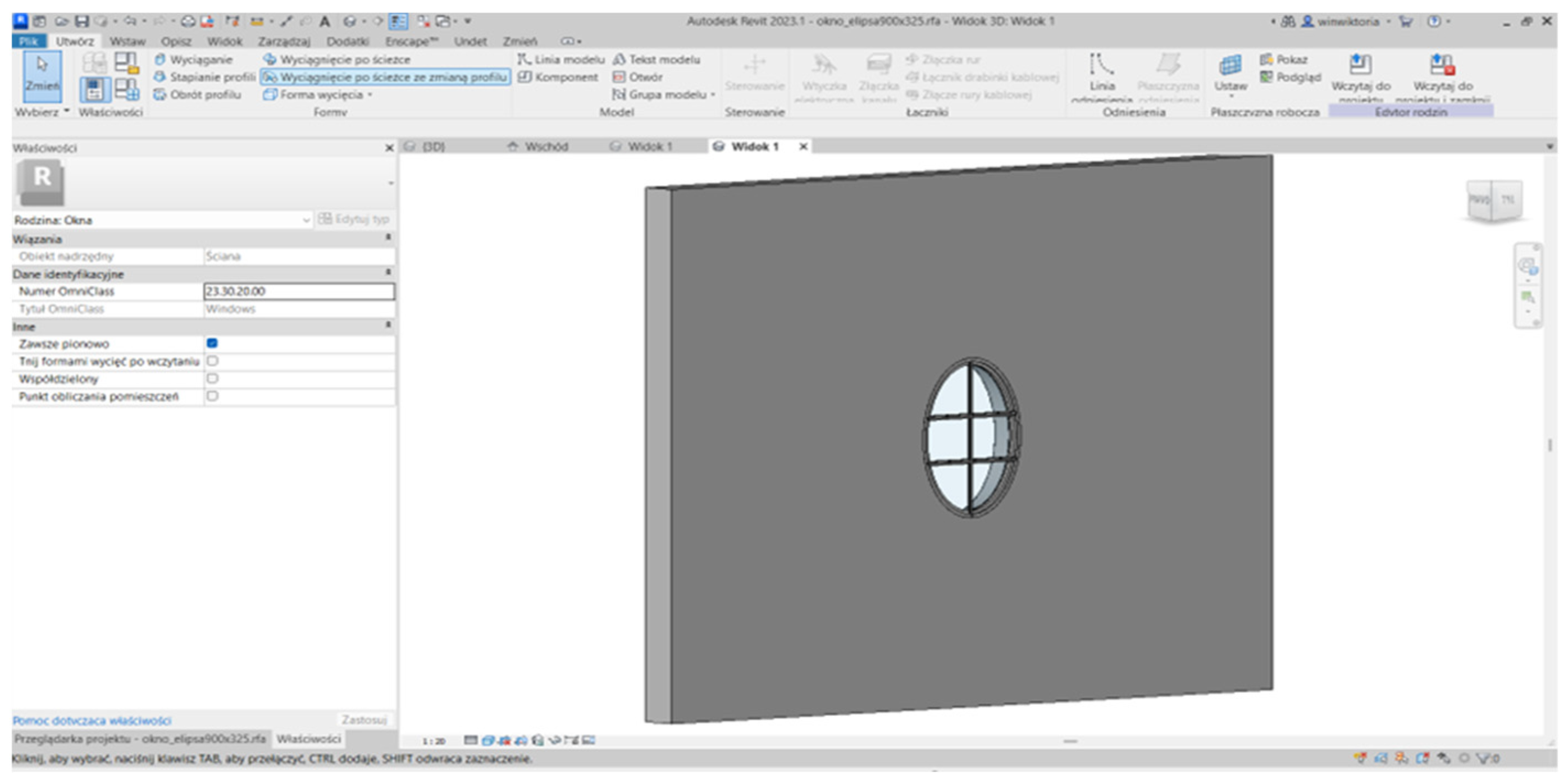
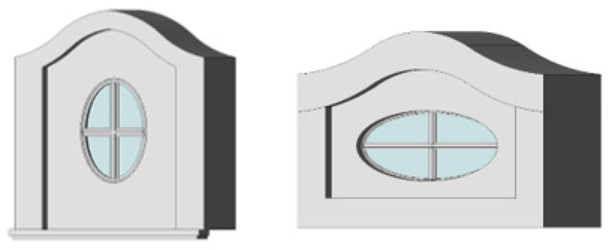
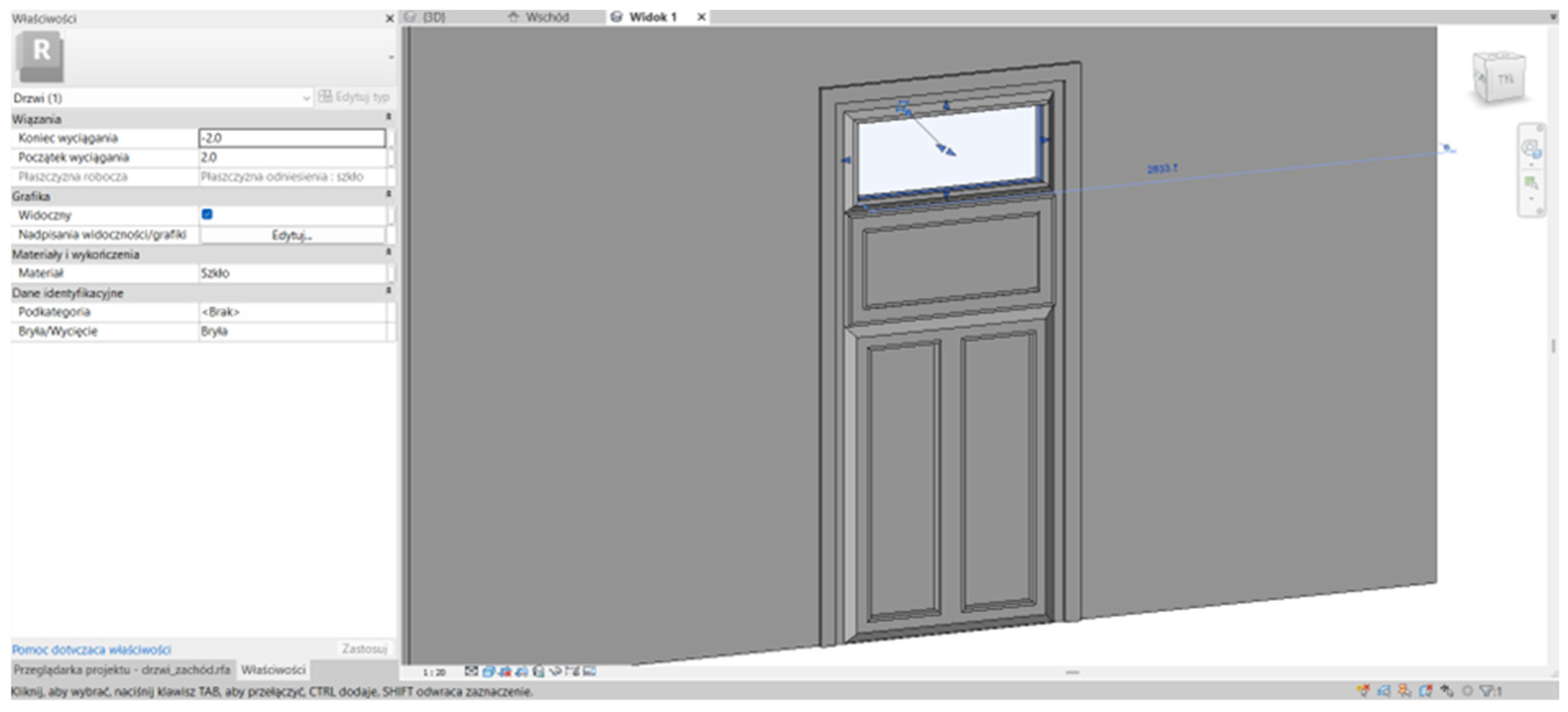
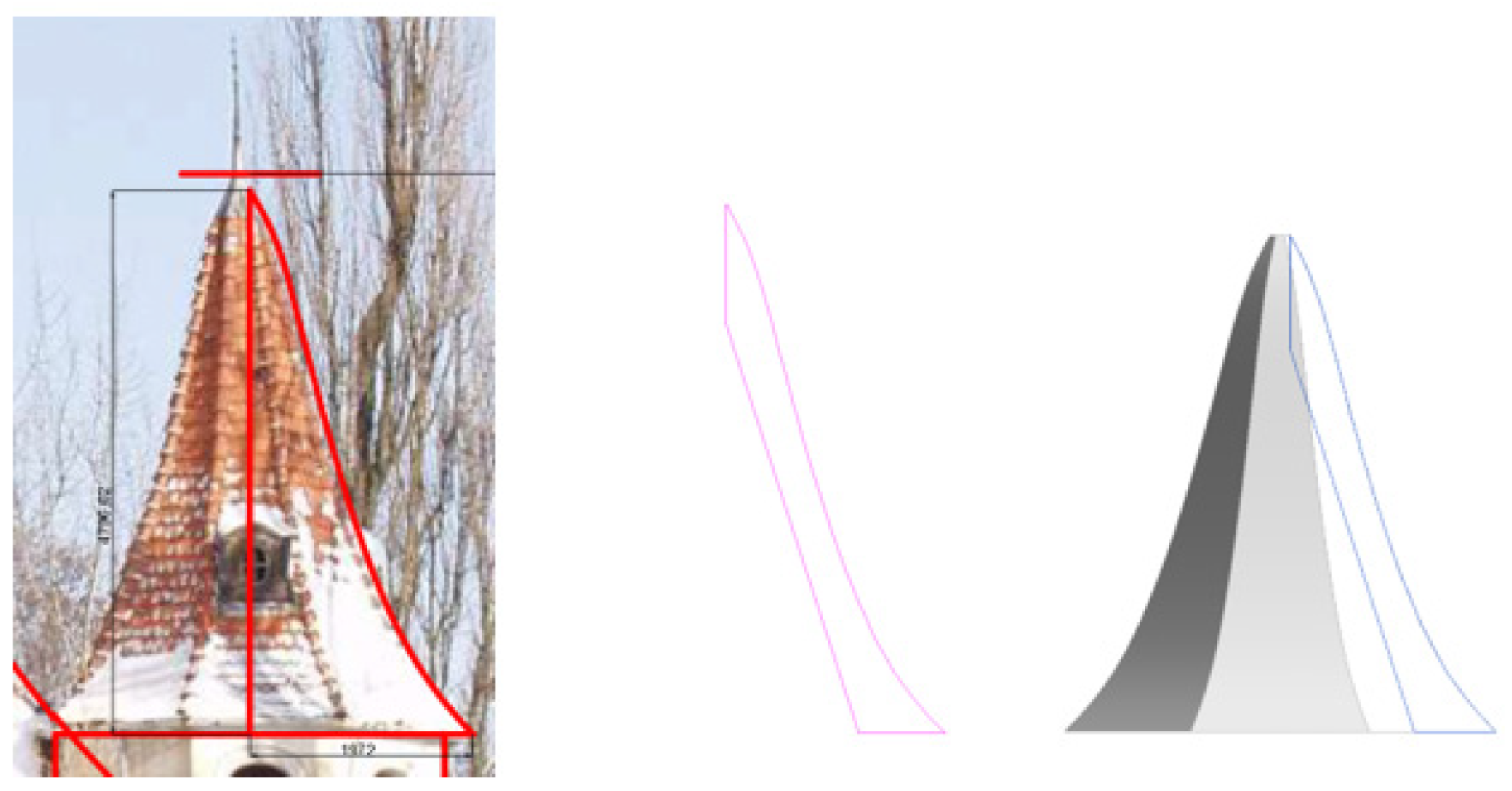
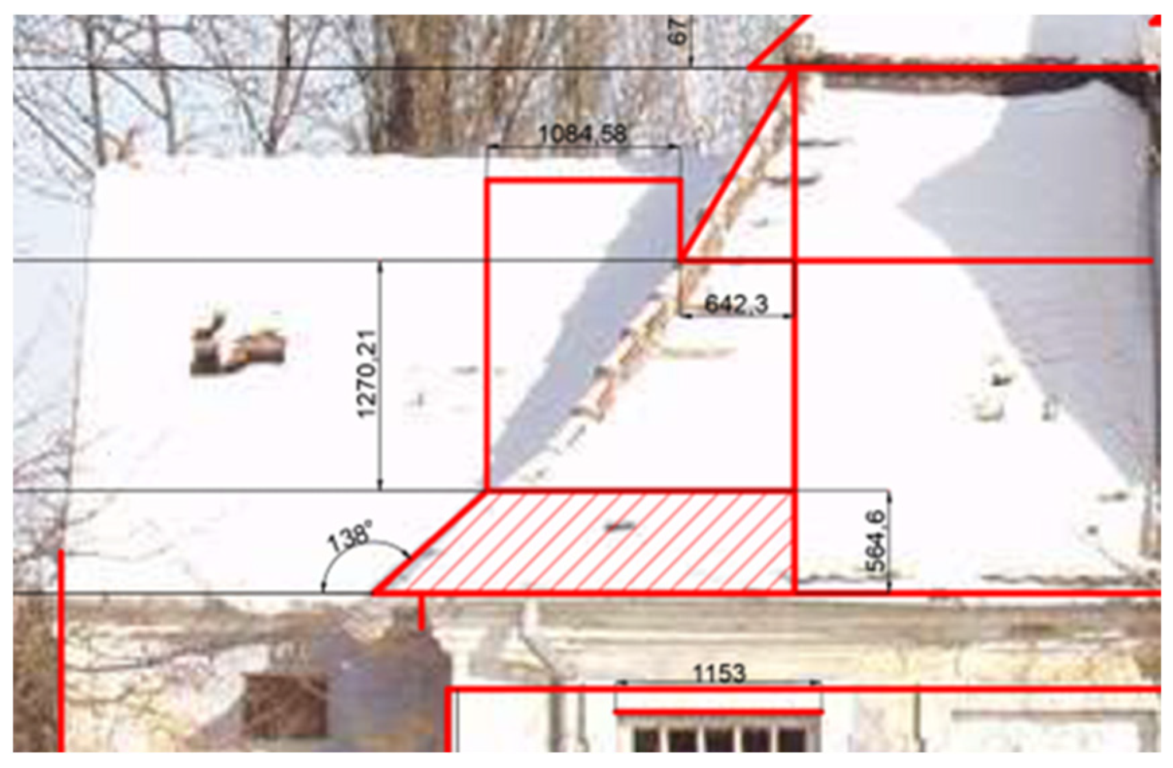
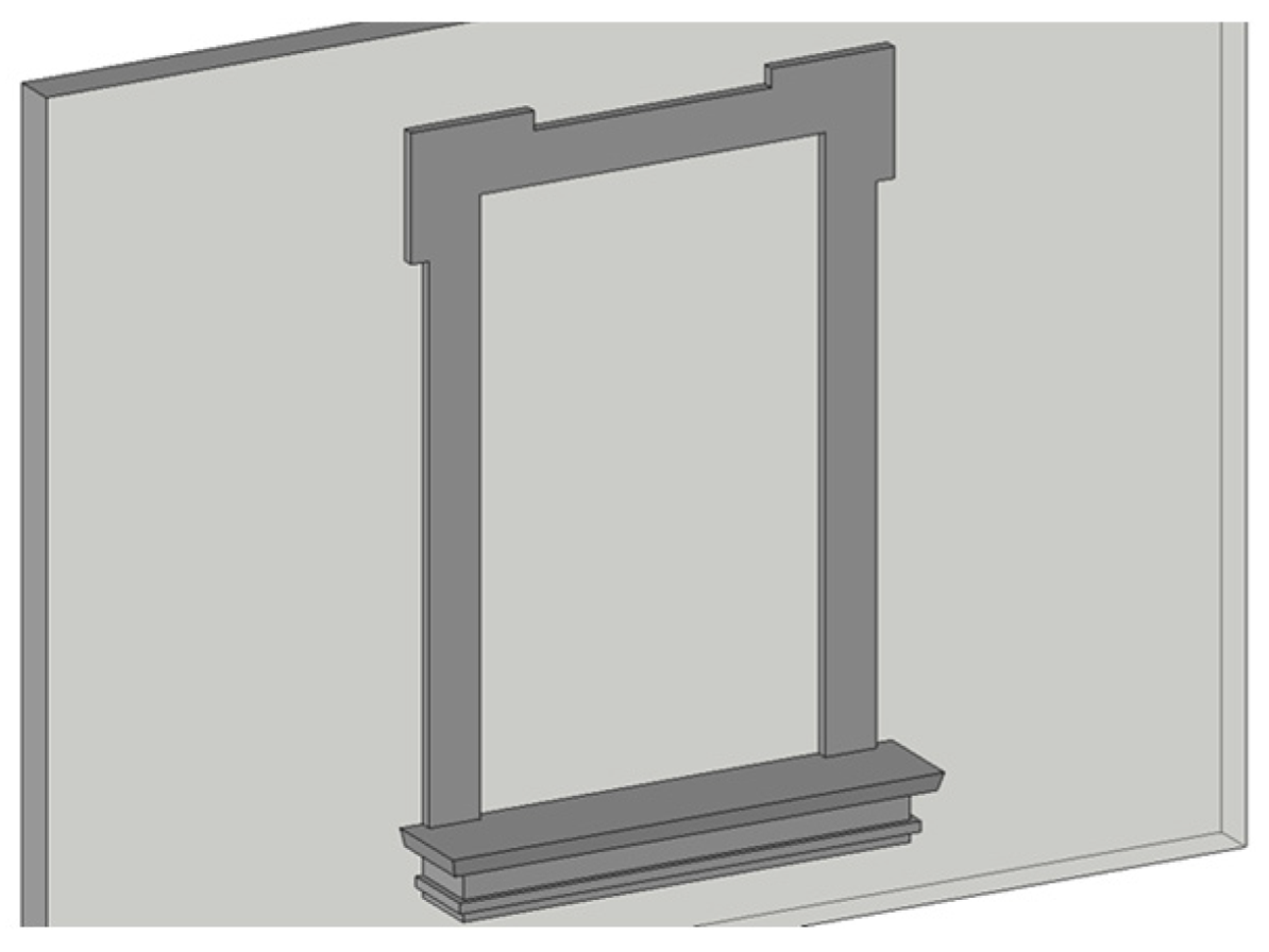
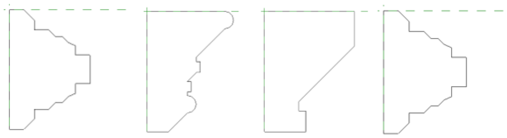
4.1. Creating a Window Family
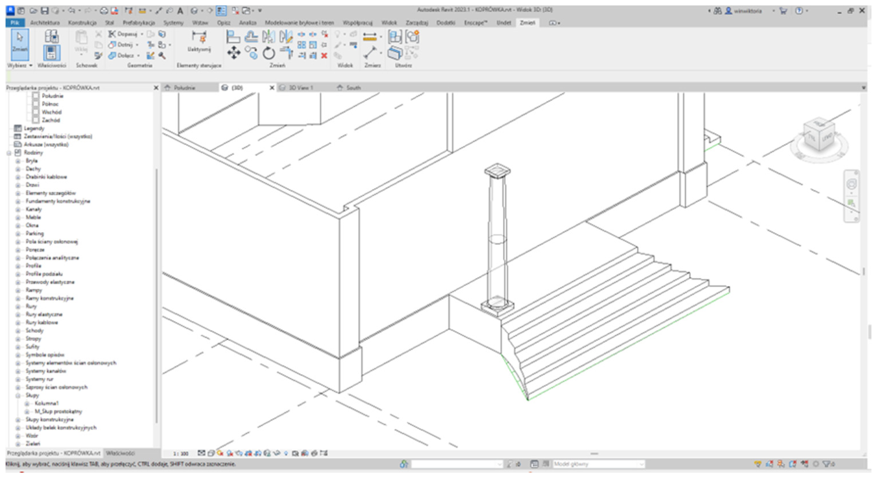
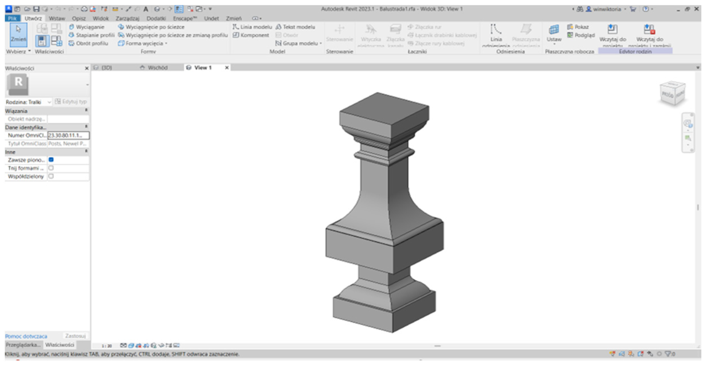
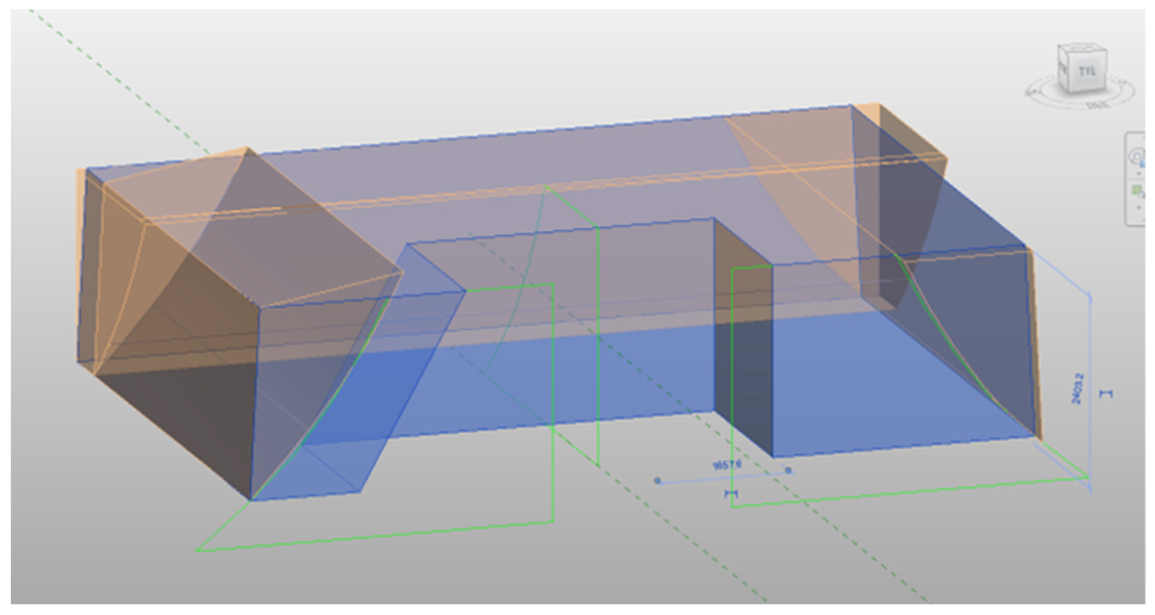
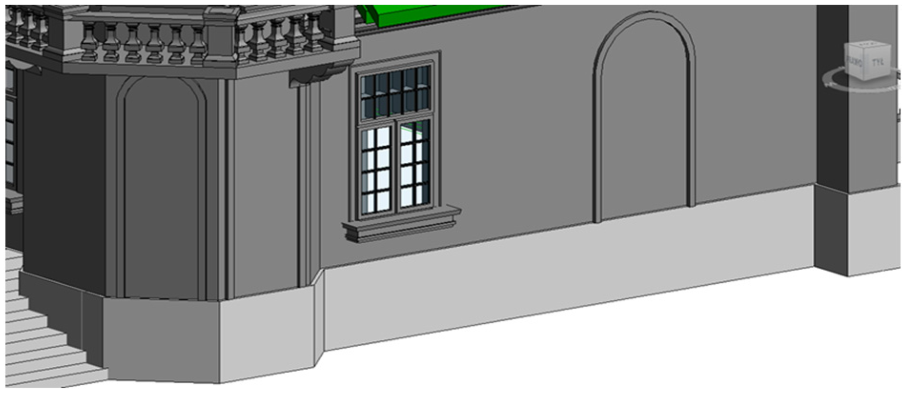
4.2. Creating the HBIM Model
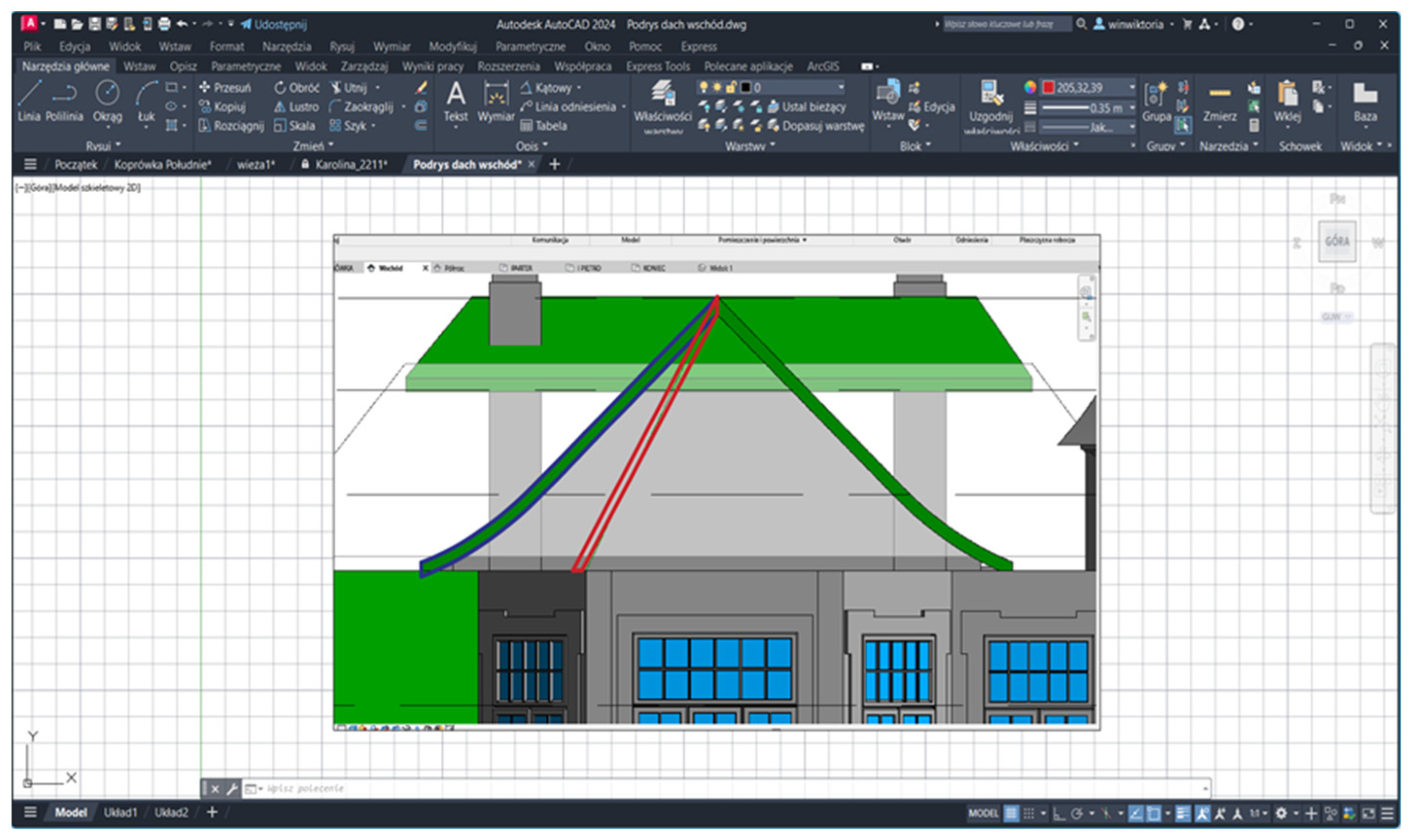
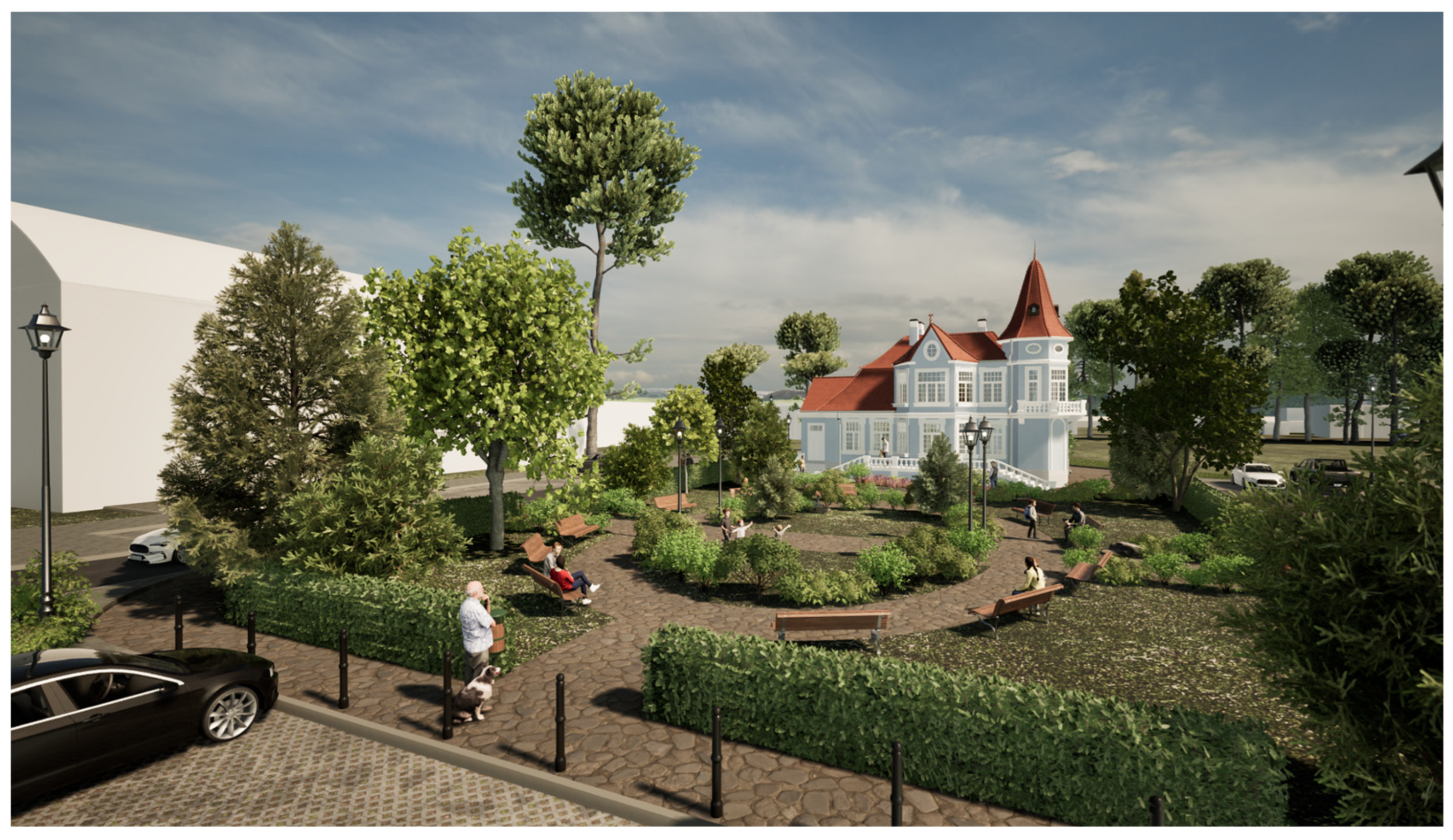
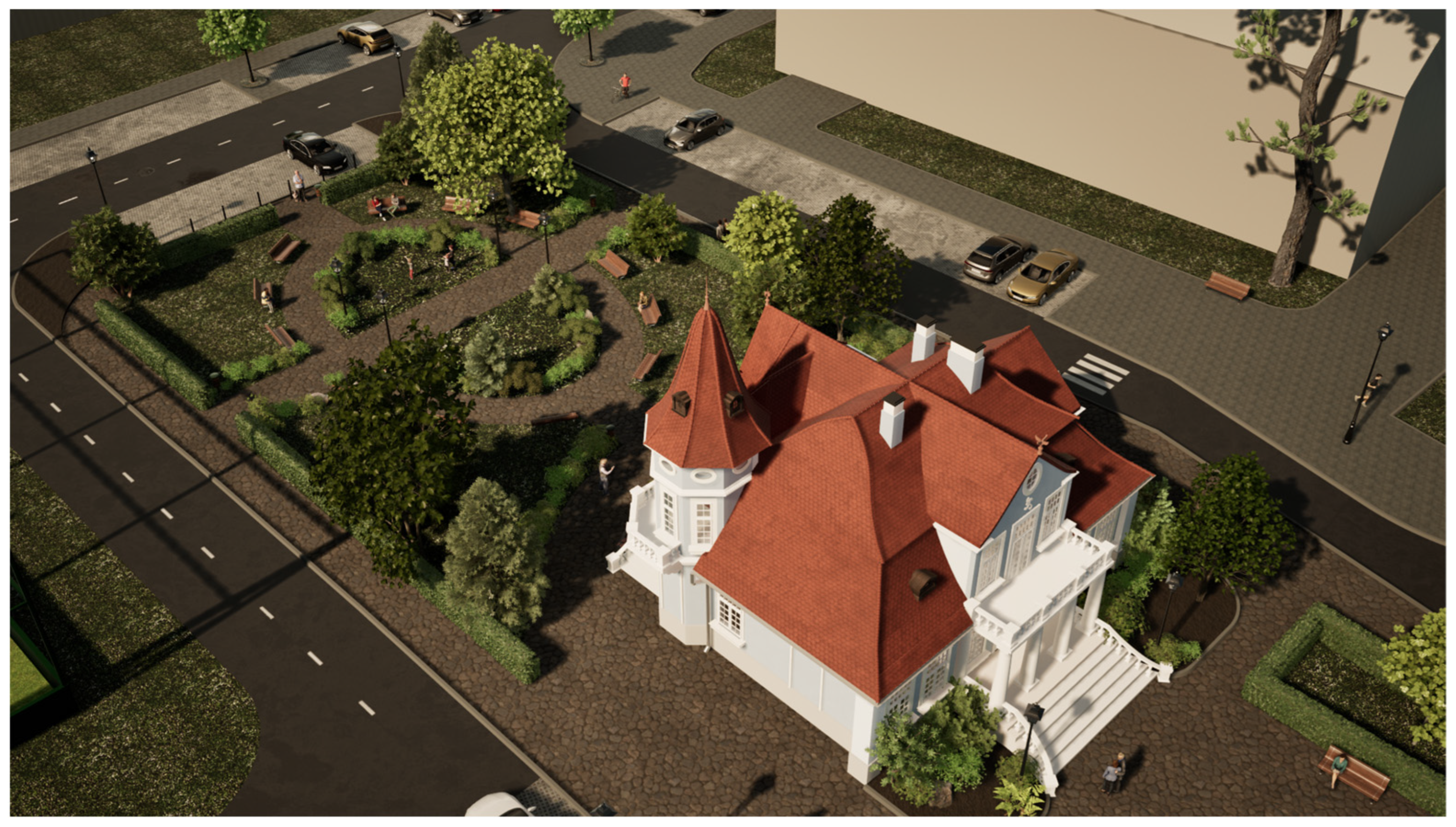
4.3. Three-Dimensional Visualization
5. Discussion and Conclusions
Author Contributions
Funding
Data Availability Statement
Acknowledgments
Conflicts of Interest
References
- Jastrzębska, A. Profesor Hilary Koprowski—Honorowy Obywatel Celestynowa; Celestynowskie Towarzystwo Kulturowe: Celestynów, Poland, 2024; pp. 12–17. (In Polish) [Google Scholar]
- Film “Powrót” cz. I Hilary Koprowski, Direction: Celestynowskie Towarzystwo Kulturalne, 2010. “Powrót” film cz.I. Hilary Koprowski—YouTube. Available online: https://www.youtube.com/watch?v=GZndqYEuRAE (accessed on 15 September 2024). (In Polish).
- Oral, E.; Chawla, R.; Wijkstra, M.; Mahyar, N.; Dimara, E. From information to choice: A critical inquiry into visualization tools for decision making. IEEE Trans. Vis. Comput. Graph. 2023, 30, 359–369. [Google Scholar] [CrossRef] [PubMed]
- Borkowski, A.S. Propedeutyka BIM—Filozofia Modelowania Informacji o Obiekcie Budowlanym; Oficyna Wydawnicza Politechniki Warszawskiej: Warszawa, Poland, 2024; 190p. (In Polish) [Google Scholar]
- Mesároš, P.; Mandičák, T. Exploitation and benefits of BIM in construction project management. IOP Conf. Ser. Mater. Sci. Eng. 2017, 245, 062056. [Google Scholar] [CrossRef]
- Radziejowska, A.; Sobotka, B. Analysis of the social aspect of smart cities development for the example of smart sustainable buildings. Energies 2021, 14, 4330. [Google Scholar] [CrossRef]
- Osello, A.; Lucibello, G.; Morgagni, F. HBIM and Virtual Tools: A New Chance to Preserve Architectural Heritage. Buildings 2018, 8, 12. [Google Scholar] [CrossRef]
- Baghalzadeh Shishehgarkhaneh, M.; Keivani, A.; Moehler, R.C.; Jelodari, N.; Roshdi Laleh, S. Internet of Things (IoT), Building Information Modeling (BIM), and Digital Twin (DT) in construction industry: A review, bibliometric, and network analysis. Buildings 2022, 12, 1503. [Google Scholar] [CrossRef]
- Ramírez Eudave, R.; Ferreira, T.M. On the suitability of a unified GIS-BIM-HBIM framework for cataloguing and assessing vulnerability in Historic Urban Landscapes: A critical review. Int. J. Geogr. Inf. Sci. 2021, 35, 2047–2077. [Google Scholar] [CrossRef]
- Borkowski, A.S.; Olszewska, P. HBIM Model as a Digital Twin on the Example of the Gawrych Cottage in the Kurpie Open Air Museum in Nowogród|Model HBIM jako cyfrowy bliźniak na przykładzie Chaty z Gawrych w Skansenie Kurpiowskim w Nowogrodzie. Wiadomości Konserw. 2024, 77, 137–148. [Google Scholar]
- Khalil, A.; Stravoravdis, S. H-BIM and the domains of data investigations of heritage buildings current state of the art. Int. Arch. Photogramm. Remote Sens. Spat. Inf. Sci. 2019, 42, 661–667. [Google Scholar] [CrossRef]
- Gara, F.; Nicoletti, V.; Arezzo, D.; Cipriani, L.; Leoni, G. Model updating of cultural heritage buildings through swarm intelligence algorithms. Int. J. Archit. Herit. 2025, 19, 259–275. [Google Scholar] [CrossRef]
- Nagy, G.; Ashraf, F. HBIM platform & smart sensing as a tool for monitoring and visualizing energy performance of heritage buildings. Dev. Built Environ. 2021, 8, 100056. [Google Scholar]
- Jouan, P.; Hallot, P. Digital twin: A HBIM-based methodology to support preventive conservation of historic assets through heritage significance awareness. Int. Arch. Photogramm. Remote Sens. Spat. Inf. Sci. 2019, 42, 609–615. [Google Scholar] [CrossRef]
- Barrile, V.; Bernardo, E.; Bilotta, G. An experimental HBIM processing: Innovative tool for 3D model reconstruction of morpho-typological phases for the cultural heritage. Remote Sens. 2022, 14, 1288. [Google Scholar] [CrossRef]
- Abreu, N.; Pinto, A.; Matos, A.; Pires, M. Procedural point cloud modelling in scan-to-BIM and scan-vs-BIM applications: A review. ISPRS Int. J. Geo Inf. 2023, 12, 260. [Google Scholar] [CrossRef]
- Borkowski, A.S.; Maroń, M. Semantic Enrichment of Non-graphical Data of a BIM Model of a Public Building from the Perspective of the Facility Manager. Big Data Cogn. Comput. 2024, 8, 138. [Google Scholar] [CrossRef]
- Piantanida, P.; Zerbinatti, M.; Fasana, S.; Cardani, G. Even the Details Make a Difference: Problems and Solutions Regarding Interventions on Historic Masonry Cornices. In Proceedings of the 18th International Brick and Block Masonry Conference, Birmingham, UK, 21–24 July 2024; Springer Nature: Cham, Switzerland, 2024; pp. 825–832. [Google Scholar]
- Kossakowski, P.G. Visual programming as modern and effective structural design technology—Analysis of opportunities, challenges, and future developments based on the use of dynamo. Appl. Sci. 2023, 13, 9298. [Google Scholar] [CrossRef]
- Kochański, Ł.; Borkowski, A.S. Automating the conceptual design of residental areas using visual and generative programming. J. Eng. Des. 2024, 35, 195–216. [Google Scholar] [CrossRef]
- Marczyński, M.; Pękacz, A. Hilary Koprowski-polski lekarz, wirusolog i immunolog. Humanum. Międzynarodowe Stud. Społeczno Humanist. 2018, 1, 119–123. (In Polish) [Google Scholar]
- Sakin, M.; Kiroglu, Y.C. 3D Printing of Buildings: Construction of the Sustainable Houses of the Future by BIM. Energy Procedia 2017, 134, 702–711. [Google Scholar] [CrossRef]
- Martinelli, L.; Calcerano, F.; Gigliarelli, E. Methodology for an HBIM workflow focused on the representation of construction systems of built heritage. J. Cult. Herit. 2022, 55, 277–289. [Google Scholar] [CrossRef]
- Bacci, G.; Bertolini, F.; Bevilacqua, M.G.; Caroti, G.; Martínez-Espejo Zaragoza, I.; Martino, M.; Piemonte, A. HBIM methodologies for the architectural restoration. The case of the ex-church of San Quirico all’Olivo in Lucca, Tuscany. Int. Arch. Photogramm. Remote Sens. Spat. Inf. Sci. 2019, 42, 121–126. [Google Scholar] [CrossRef]
- Borkowski, A.S.; Kubrat, A. Integration of Laser Scanning, Digital Photogrammetry and BIM Technology: A Review and Case Studies. Eng 2024, 5, 2395–2409. [Google Scholar] [CrossRef]


| Name and Software | Purpose of Use | Price in PLN (Current as of 2024) |
|---|---|---|
| Revit (version 2023.1.3) | - creation of a virtual 3D model of the “Koprówka” with .rvt extension -modeling of individual building elements (creation of families with .rfa extension) | Autodesk offers a choice of several plans for Revit: - 1 month (price: 1870), - 1 year (price: 14,840), - 3 years (price: 44,526). |
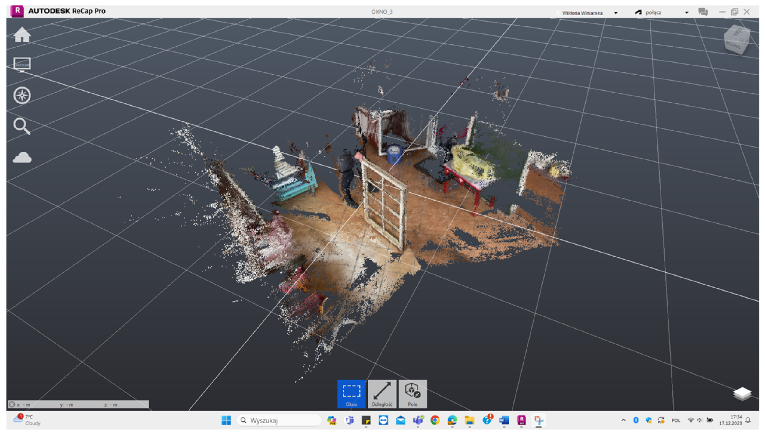
| Autodesk ReCap Pro (version v.24.1) | - clearing point clouds of unnecessary coordinates and preparing them for further modeling | Autodesk offers a choice of several plans for ReCap Pro: - 1 month (price: 246), - 1 year (price: 1987), - 3 years (price: 5966). |
| AutoCAD (version 24.3.61.0) | - dimensioning of other parts of the building based on known window dimensions; applying dimensions to photos | Autodesk offers a choice of several plans for AutoCAD: - 1 month (price: 1286), - 1 year (price: 10,345), - 3 years (price: 31,027). |
| Twinmotion (version 2023.2.4) | - creation of a visualization showing the fit of “Koprówka” into the surroundings with the existing state of land development | 0.00 (for the purpose of completing the thesis, the free version of the software available to students was used. Plans for an expanded version of the software are available at: https://www.twinmotion.com/en-US/license [accessed 2 November 2024]) |
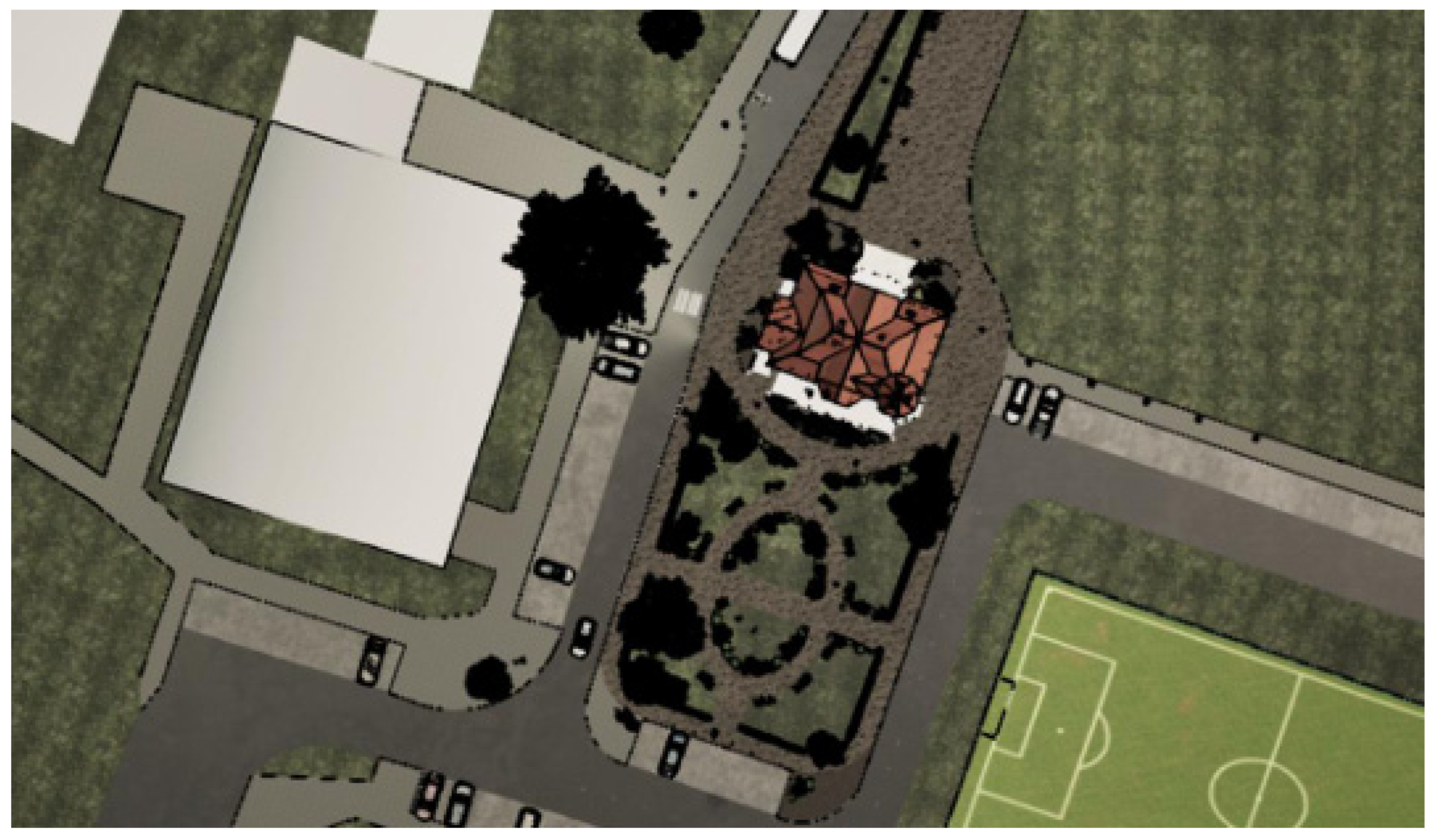
| ArcGIS Pro (version 3.0.36056) | - development of maps | PLN 0.00 (for the purpose of completing the thesis, the free version of the software available to students was used. Plans for an extended version of the software are available at: https://www.esri.com/en-us/arcgis/products/arcgis-pro/buy [accessed 7 December 2024]) |
| Undet for Revit (version 24.2.0.2527) | - creation of raster images from cross-sections through point clouds, which were used to model the window family | 0.00 (for the purpose of completing the thesis, a free, 3-month version of the software available to students was used. Plans for an expanded version of the software are available at: https://www.undet.com/undet products/undet-for-revit-point-cloud/ [accessed 7 August 2024]) |
| Undet Indexer (version 1.8.6.2485) | - change the .rcp extension generated in Autodesk ReCap Pro to an .ipcp extension, allowing the use of Undet software features | 0.00 (for the purpose of completing the thesis, a free, 3-month version of the software available to students was used. Plans for an expanded version of the software are available at: https://www.undet.com/undetproducts/undet-for-revit-point-cloud/ [accessed 7 August 2024]) |
| Scanivers (version 3.1.3) | - Window image registration using LiDAR scanning technology | 0.00 (software available free of charge) |
| Concepts (version 6.15.1) | - dimensioning of other parts of the building based on known window dimensions; applying dimensions to photos | 0.00 (software available free of charge) |
| File | Given Name | Properties of the Point Cloud |
|---|---|---|
| Scaniverse.las | “Window 1” | Geometry: 112 K vertices, 207 K triangles, Size: 121.3 MB, Processing: Area mode, 8 K texture |
| Scaniverse 2023-12-02 131243.las | “Window 2” | Geometry: 72 K vertices, 132 K triangles, Size: 78.7 MB, Processing: Area mode, 8 K texture |
| Scaniverse 2023-12-02 132053.las | “Window 3” | Geometry: 231 K vertices, 417 K triangles, Size: 220.7 MB Processing: Area mode, 8 K texture |
| Scaniverse 2023-12-02 132712.las | “Window 4” | Geometry: 239 K vertices, 428 K triangles, Size: 267.5 MB, Processing: Area mode, 8 K texture |
| Window Dimensions [cm] | Number of Occurrences of the Window in the HBIM Model |
|---|---|
| 57.5 × 124.3 | 38 |
| 70 × 89.5 | 4 |
| 89.5 × 124.3 | 8 |
| 70 × 172.5 | 1 |
| 70 × 57.5 | 3 |
| Window Dimensions [cm]. | Number of Occurrences of the Window in the HBIM Model |
|---|---|
| 32.5 × 90 | 2 |
| 48 × 70 | 1 |
| 35.7 × 58 | 5 |
| Door Dimensions [cm]. | Door Location Side of the HBIM Model |
|---|---|
| 113 × 180 | north |
| 113.7 × 188.3 | north |
| 126.7 × 260 | south |
| 165 × 267.4 | west |
| 87 × 107 | west |
| 113.8 × 187.5 | southeast |
| Given Name | Appearance of the Element |
|---|---|
| Element No. 1 | 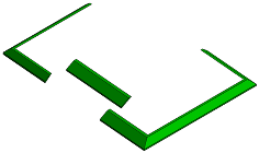 |
| Element No. 2 |  |
| Element No. 3 |  |
| Element No. 4 |  |
| Element No. 5 | 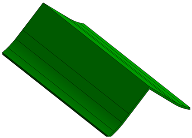 |
| Element No. 6 |  |
| Element No. 7 |  |
| Element No. 8 |  |
Disclaimer/Publisher’s Note: The statements, opinions and data contained in all publications are solely those of the individual author(s) and contributor(s) and not of MDPI and/or the editor(s). MDPI and/or the editor(s) disclaim responsibility for any injury to people or property resulting from any ideas, methods, instructions or products referred to in the content. |
© 2025 by the authors. Licensee MDPI, Basel, Switzerland. This article is an open access article distributed under the terms and conditions of the Creative Commons Attribution (CC BY) license (https://creativecommons.org/licenses/by/4.0/).
Share and Cite
Borkowski, A.S.; Winiarska, W. The HBIM Model as a Source in the Building Reconstruction Process: A Case Study of the “Koprówka” in Celestynów, Poland. Buildings 2025, 15, 1442. https://doi.org/10.3390/buildings15091442
Borkowski AS, Winiarska W. The HBIM Model as a Source in the Building Reconstruction Process: A Case Study of the “Koprówka” in Celestynów, Poland. Buildings. 2025; 15(9):1442. https://doi.org/10.3390/buildings15091442
Chicago/Turabian StyleBorkowski, Andrzej Szymon, and Wiktoria Winiarska. 2025. "The HBIM Model as a Source in the Building Reconstruction Process: A Case Study of the “Koprówka” in Celestynów, Poland" Buildings 15, no. 9: 1442. https://doi.org/10.3390/buildings15091442
APA StyleBorkowski, A. S., & Winiarska, W. (2025). The HBIM Model as a Source in the Building Reconstruction Process: A Case Study of the “Koprówka” in Celestynów, Poland. Buildings, 15(9), 1442. https://doi.org/10.3390/buildings15091442