Article

Effect of Pile Spacing on Load Bearing Performance of NT-CEP Pile Group Foundation

1
College of Civil Engineering, Jilin Jianzhu University, Changchun 130118, China
2
School of Transportation Science and Engineering, Jilin Jianzhu University, Changchun 130118, China
3
Yanji Branch of Jilin Expressway Group Co., Ltd., Yanji 133000, China
4
China Construction Fifth Engineering Bureau Co., Ltd., Changsha 410004, China
*
Author to whom correspondence should be addressed.
Buildings 2025, 15(9), 1404; https://doi.org/10.3390/buildings15091404
Submission received: 27 March 2025 / Revised: 14 April 2025 / Accepted: 21 April 2025 / Published: 22 April 2025
(This article belongs to the Section Building Structures)

Abstract

The NT-CEP pile is an innovative type of pile that builds upon the conventional concrete straight-hole cast-in-place pile. It primarily consists of two components: the main pile and the bearing plate. The key factors influencing its load-bearing capacity include the pile diameter, the cantilever dimensions of the bearing plate, and the slope of the bearing plate’s foot, among others. The pile spacing significantly influences the bearing capacity of NT-CEP pile group foundations. The overall bearing capacity of an NT-CEP pile group foundation is not merely the sum of the ultimate bearing capacities of individual piles; rather, it results from the interactions among the pile bodies, the cap, and the foundation soil. Advancing the design theory of NT-CEP pile groups and enhancing their practical applications in engineering requires an in-depth investigation of how different pile spacings influence the load-bearing performance of pile group foundations. This objective can be achieved by exploring the soil damage mechanisms around side, corner, and central piles. This exploration helps in clarifying the influence of pile spacing on the load-bearing performance. Based on research findings regarding the bearing capacity of single and double pile foundations, this paper utilizes ANSYS finite element simulation analysis to model six-pile and nine-pile groups. Because these arrangements are universally adopted in engineering practice, they are capable of accounting for the pile group effect under various pile spacings and row configurations. The nine-pile group comprises corner piles, side piles, and a center pile, enabling a comprehensive analysis of stress variations among piles at different positions. As six-pile and nine-pile groups represent common pile configurations, studying these two types can provide valuable insights and direct references for optimizing pile foundation design. The study systematically investigates the influence of varying piles spacings on the bearing capacity of NT-CEP pile group foundations. It concludes that, as pile spacing decreases, The displacement of the top of this pile increases. thereby enhancing the group piles effects. Conversely, increasing the spacing between piles represents an effective strategy for elevating the compressive capacity of the NT-CEP pile-group foundation. Larger spacing also increases the vertical load-bearing capacity of the central piles, enhances the lateral friction resistance of corner piles, and heightens the load-sharing proportion between the bearing plate and the pile end. Furthermore, increasing pile spacing raises the ratio of load sharing by the foundation soil for both the CEP nine-pile foundation and the CEP six-pile foundation. The reliability of the simulation study has been verified by a visualization small scale model test of a half cut pile.

1. Introduction

The new type concrete expanded plate (NT-CEP) pile represents an innovative, variable cross sectional cast in situ pile [1,2]. This innovative type of pile features unique structural characteristics that set it apart from traditional piles [3,4]. Unlike ordinary equal-diameter piles, the bearing capacity of single-disk piles is significantly higher [5,6]. Due to their low construction cost, high bearing capacity, and minimal settlement, NT-CEP piles are widely used in engineering applications [7,8].
While studies on NT-CEP single and double piles [5,9] are relatively well developed, research on NT-CEP pile groups is limited, and most investigations focus on equal-diameter piles; a systematic framework has yet to be established and requires further exploration. This paper builds upon previous research to examine the influence of piles spacing on the compressive capacity of NT-CEP pile groups. To ensure representativeness, groups of six and nine piles were selected as research subjects, encompassing corner piles, side piles, and central piles [10,11]. Pile spacing was treated as a singular variable in the simulation, leading to the establishment of five sets of ANSYS Workbench 2022R1 finite element analysis models for the six-pile (2 × 3) and nine-pile (3 × 3) configurations. Based on earlier findings from the research group, the parameters for the pile body and soil were determined [12,13], and five simulations were conducted for each pile group with varying pile spacings. ANSYS software recorded the stress, displacement, and soil failure states surrounding the NT-CEP pile group under load at each stage. Finally, a comprehensive analysis of the simulation results for each pile group was conducted to identify the soil failure patterns around the side, corner, and central piles. This study elucidates how pile spacing impacts the compressive bearing performance of pile groups. By doing so, it offers scientific backing for improving the calculation theory concerning the compressive bearing capacity of NT-CEP pile groups with different pile spacings in real-world engineering scenarios.
In the early stage, the research group independently developed a small proportion half-section pile shape test [14], compared it with ANSYS finite element simulation, and found that the test results were consistent with the simulation analysis, which further confirmed the correctness of the study on the bearing performance of NT-CEP pile by studying the pile spacing through ANSYS finite element simulation. Therefore, ANSYS finite element simulation was used for analysis in this paper.

2. ANSYS Finite Element Modeling

2.1. Selection of Unit Type

Given that the stress distribution in the soil surrounding the piles is considerably more complex than that of the pile itself, and that the interaction between the soil and the pile foundation plays a crucial role in the overall stability of the structure, it is often essential to incorporate various mutually influencing parameters in practical applications to account for these nonlinear factors [15,16]. Consequently, Solid65—a 3D solid unit—was adopted as the pile element type in this study. The Solid65 unit is characterized as an isotropic element consisting of eight nodes, Each node shows three degrees of freedom respectively in the x, y, and z directions. In accordance with the specific needs of the actual project and the preliminary tests carried out by the research group, the pile material was modeled using a linear elastic approach, with parameters referencing C35 concrete [17]. The pile body’s constitutive relationship was implemented using an elastic–plastic model [18,19], while the soil constitutive model employed the Drucker–Prager function [20,21] (referred to as DP model). The SOLID45 unit was utilized to simulate the soil elements, also adopting the elastoplastic model. The designed soil is modeled as a homogeneous and isotropic elastoplastic material.

2.2. Material Properties and Meshing

The material parameters for both the soil and pile were ascertained based on the actual project specifications and the results of the preliminary tests conducted by the research group [5],ensuring consistency with previous studies. The NT-CEP pile body is constructed from C35 concrete. To accurately simulate the side friction resistance of the pile in real-world engineering applications, a pile–soil friction coefficient with a value of 0.3 is applied. The material properties of the simulated pile–soil system are presented in Table 1. It should be noted that Table 1 focuses on the material details.
According to the prior research findings of the research team, the corresponding pile length and pile diameter were selected. This selection allows for an accurate simulation of the actual working conditions of the NT-CEP pile group foundation under load, while effectively excluding the influence of boundary effects. This paper adopts a 1:1 scale model for the CEP finite element simulation, with the spacing between piles being the only variable. In the CEP pile group foundation model, the pile length is 8.0 m, and the pile diameter is 0.5 m. The supporting plate features an upper and lower asymmetric structure, having an upper slope angle of 35 degrees and a lower slope angle of 27 degrees. The overhang diameter of the plate is 750 mm, and the top of the bearing plate is positioned 3.5 m above the bottom surface of the cap. Five simulation groups, labeled J1, J2, J3, J4, and J5, were designed. The schematic diagram of the model piles and the section layout scheme are presented in Figure 1. This pile size data for the nine-pile model indicates that the net spacing of the trays for J1, J2, J3, J4, and J5 is 1875 mm, 2250 mm, 2625 mm, 3000 mm, and 3375 mm, respectively. The corresponding pile spacings (S) are 3875 mm, 4250 mm, 4625 mm, 4625 mm, 5000 mm, and 5375 mm. Six pile size parameters of the model pile body: L1, L2, L3 and L4, L5 net spacing of row with the tray P (mm), respectively: 2250 mm, 2625 mm, 2625 mm, 2625 mm, 3000 mm. With the pile spacing S (mm) is respectively: 4250 mm, 4625 mm, 4625 mm, 4625 mm, 5000 mm. The front row from the back row pile spacing Sa (mm) is respectively: 4250 mm, 4250 mm, 4650 mm, 5000 mm, 5000 mm.
In this simulation analysis, the mapping grid division method is employed. The quantity of finite grid-shaped rules generated through this approach is significantly fewer than that of the corresponding free grids. This characteristic enables the guarantee of both the accuracy and precision of the calculation outcomes. The pile–soil model after division is illustrated in Figure 2.
To further enhance the accuracy of the simulation analysis, a fine-mesh division strategy is implemented for the soil around the bearing plate and the piles in contact with it. For the soil area with a relatively minor force influence and the upper force-transfer structure, a method of appropriately enlarging the grid is adopted. To better satisfy the requirements of actual engineering data, the soil grid at and around the load-bearing disk is made more standardized. This modeling employs multi-area division, covering both hexahedral and tetrahedral area divisions, and the load-bearing disk area is encrypted. The grid division as well as the local refinement of the pile-group foundation model are depicted in Figure 2.

3. Analysis of ANSYS Finite Element Simulation Results

3.1. Analysis of Vertical Load–Pile-Top Displacement Curve

Based on the simulation calculations of each group of models featuring diverse pile spacings, the displacements and settlements of foundation piles under different loads were extracted. Additionally, a settlement of 60 mm was taken as the control condition for the vertical ultimate bearing capacity. The vertical load-top displacement curves for nine-pile foundations under various loads, along with the load-top displacement data curves of six-pile foundations under different loads, were drawn., as shown in Figure 3.
It can be observed from Figure 3a that, for the six piles, the top displacements of L3, L4, and L5 are significantly smaller than those of L1. This indicates that increasing the pile spacing within the same row can enhance the compressive bearing capacity of the pile group foundation. However, when the net distance between the ends of the disks exceeds four times the overhang diameter of the disks, the degree of improvement diminishes. The pile top displacement of group L2 is greater than that of group L1, suggesting that the reduction in the distance between the front and back piles increases the interaction between the piles, leading to an increase in the settlement of the pile group foundation. When the pile top displacements of groups L3 and L4 reach 60 mm, the compressive bearing capacity of group L4 is higher than that of group L3. This implies that when the pile spacing within the same row and the front–back pile spacing of the CEP six-pile foundations are arranged asymmetrically, increasing the front–back pile spacing can slightly enhance the compressive bearing capacity, albeit with a limited improvement range.
As is evident from Figure 3b, during the initial phase of loading, the top displacement values of the models with different pile spacings are basically the same. When the load at the top attains 6545 kN, it is clearly observable that an increase in the pile spacing can lead to a reduction in the top displacement. Moreover, as the pile spacing grows, the interaction effect between adjacent piles gradually diminishes. However, the enhancement of the compressive capacity is not linear, indicating that there exists an optimal range for the improvement of pile spacing with respect to the compressive capacity. The displacement data of each model at a load of 7295 kN were extracted, and the displacement reduction rate of each group was calculated relative to that of group J1. Subsequently, the curve of the pile-top displacement reduction rate was plotted, as illustrated in Figure 4.
As is evident from Figure 4, the reduction rates of pile-top displacements for groups J2, J3, J4, and J5 exhibit a non-linear increase as the distance between the piles expands. Moreover, the reduction rate of the pile-top displacement of group J5 is not significantly different from that of group J4. This indicates that once the clear distance between the ends of the disks surpasses by fourfold the overhang diameter of the disk, the rate of reduction in displacement at the pile-top is restricted. Therefore, to control the net distance between the disk ends of the CEP nine pile foundation, this must be 3.5 to 4 times the disk overhang diameter.

3.2. Comparative Analysis of Soil Displacement Cloud Map Around Pile

3.2.1. Soil Displacement Diagram Around Six Piles

The nephograms of soil displacement around the front and back rows of the six-pile foundations are basically identical. Thus, only the nephogram of soil displacement around the piles in the front section of each model under the ultimate load is extracted for comparative analysis, as depicted in Figure 5.
In Figure 5, 1 is the soil displacement around the cap, 2,3,and 4 is the soil displacement around the disk, and 5 is the soil displacement around the pile bottom.
Figure 5 reveals that, as pile spacing increases, when the ultimate load is attained, the displacement range of the soil surrounding the front-pile section diminishes. From the soil-displacement cloud maps of Figure 5a,b, analysis shows that the displacement range of the soil around corner piles is significantly smaller than that around side-middle piles. Moreover, as pile spacing increases, the influence range of the soil around side-middle piles gradually shrinks. The mutual influence range of the soil around the corner piles and side-middle piles in L4 is smaller than that in L3. Consequently, when subjected to identical loads, group L4 exhibits smaller pile-top displacement. Therefore, when a two-row pile-arrangement scheme is adopted for CEP six-pile foundations, keeping the pile spacing in group L4 unchanged while increasing the front and back pile spacing is a more reasonable arrangement method.

3.2.2. Cloud Map of Jiudang Soil Displacement

In order to distinctly contrast the displacements of the soil surrounding the foundation piles at various positions when the load remains the same, the displacement cloud images of the models in sections I-I and III-III were selected when the J1 reached its ultimate load, as shown in Figure 6 and Figure 7.
In Figure 5, 1 is the soil displacement around the cap, 2,3, and 4 is the soil displacement around the disk, and 5 is the soil displacement around the pile bottom.
Under pile-top loading, the displacement of soil near the pile body is greater, decreasing gradually with distance from the pile, thus exhibiting a gradient distribution. If a region exhibits a sharp local color change, it indicates a sudden stress concentration in that area.
Figure 6 clearly demonstrates that an increase in pile spacing can diminish the overlapping extent of the influence of bearing disks on the soil between piles. thereby enhancing the vertical bearing capacity of central piles. By comparing Figure 6 and Figure 7, it is evident that, when the spacing between piles remains constant, the range of soil interaction in section I-I is notably smaller than that in section III-III. Overall, it can be seen that the soil between the piles takes the central pile as the axis, and the soil displacement around the piles decreases from the inside out. Due to the pile-group effect, the soil interaction between two adjacent piles is significant, resulting in the displacement of the middle pile being greater than that of the piles on both sides. Once the pile spacing attains fourfold the overhang diameter, the displacement discrepancies among foundation piles at diverse positions are minor. Thus, it represents a rational approach to regulate the pile spacing of nine-pile CEP foundations within the range of 3.5 to 4 times the overhang diameter.

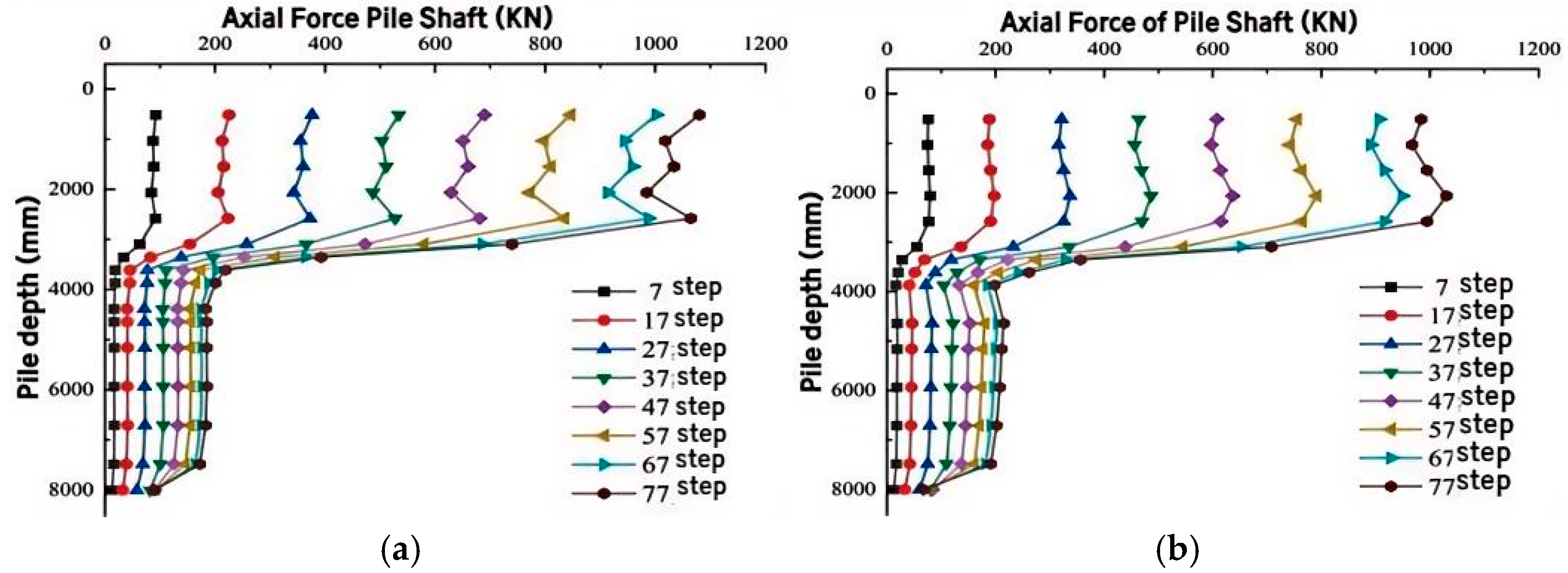
3.3. Analysis of Axial Force and Side Friction of Foundation Pile

3.3.1. Analysis of Axial Force and Side Friction of Six Piles

To further investigate the axial force variations of corner piles and side piles in each group of models during the loading process, the axial force data of corner piles and side piles in each group at 15 specific position points under different loading steps were also extracted. To present the axial force changes of the pile bodies more intuitively, the axial force curves of the pile bodies, which depict how the axial force varies with the pile depth, were plotted separately, as shown in Figure 8 and Figure 9.
As can be observed from Figure 8 and Figure 9, the axial forces of the middle corner pile and the middle side pile of the CEP six-pile foundation basically conform to the variation law with respect to the pile depth. That is, the axial forces of the foundation piles gradually converge as the depth increases, and the axial force of the corner pile is smaller than that of the middle side pile. When comparing L3 and L4, it is found that, when the inter-pile distance in the same row is the same, reducing the distance between the front and back piles will decrease the axial forces of both the corner piles and the side piles. Increasing the distance between the front and back piles will decrease the axial force of the corner piles, while the axial force of the side piles changes slightly.
By analyzing the slope of the curve representing the relationship between the axial force and the pile depth, the lateral friction resistance of each section of the pile body was examined. The lateral friction resistances of each part of the corner pile and the side pile body basically change in a similar manner. When comparing L2, L3, and L4, it is found that, when the inter-pile distance in the same row is the same, either reducing or increasing the inter-pile distance between the front and back piles will result in a more obvious trend of the lateral friction resistance at the top of the bearing disk of the corner pile increasing first and then decreasing. However, the variation trend of the pile side friction resistance on the upper part of the bearing plate of the middle pile is not obvious. The pile side friction resistance below the bearing plate does not change with the variation of the distance between the front and back piles.

3.3.2. Analysis of Pile Axial Force and Pile Side Friction Resistance of Nine-Pile Foundations

Based on the pre-simulation, 15 specific position points with different axial forces of the foundation pile body under various pile spacings were selected. The points at the bearing disk were refined further. Then, the curve depicting the variation of the axial force along the pile depth was drawn, as presented in Figure 10 and Figure 11.
As can be observed from Figure 10 and Figure 11, when the pile spacing is small, the axial force of the pile body is the largest in the corner pile and the smallest in the central pile. However, as the pile spacing increases, the axial force at the top of the foundation piles in group J5 is exactly the opposite. This is because the pile group effect is significant when the pile spacing is small. When the pile spacing is increased while the cap height remains unchanged, the span of the cap between two piles increases. This situation is tantamount to a reduction in the stiffness of the pile cap, and the dispersive effect of the load applied at the pile-top is diminished. Since the central pile is closest to the center of the cap, the axial force of the central pile increases significantly. The axial force of each pile body drops sharply at the bearing plate. Finally, in the lower part of the bearing plate, the axial forces of the corner pile and the central pile show a tendency to become equal. Additionally, as the pile spacing increases, the disparity between the axial forces of the corner pile and the central pile gradually lessens.
From Figure 10 to Figure 11, it can be seen that, as the pile spacing increases, the pile side friction resistance in the upper part of the pile body of the central pile’s bearing disk weakens. This is because an increase in the pile spacing directly leads to a decrease in the gripping effect that adjacent piles have on the soil situated between them around the central pile, resulting in a smaller overlapping range of soil stresses between the piles. The axial force curve of the pile body in the lower part of the corner pile’s bearing plate increases gradually, while that of the central pile decreases gradually. This suggests that, as the pile spacing increases, the lateral friction resistance of the pile body in the lower part of the corner pile’s bearing plate rises gradually, whereas the lateral friction resistance of the pile body in the lower part of the central pile drops gradually.

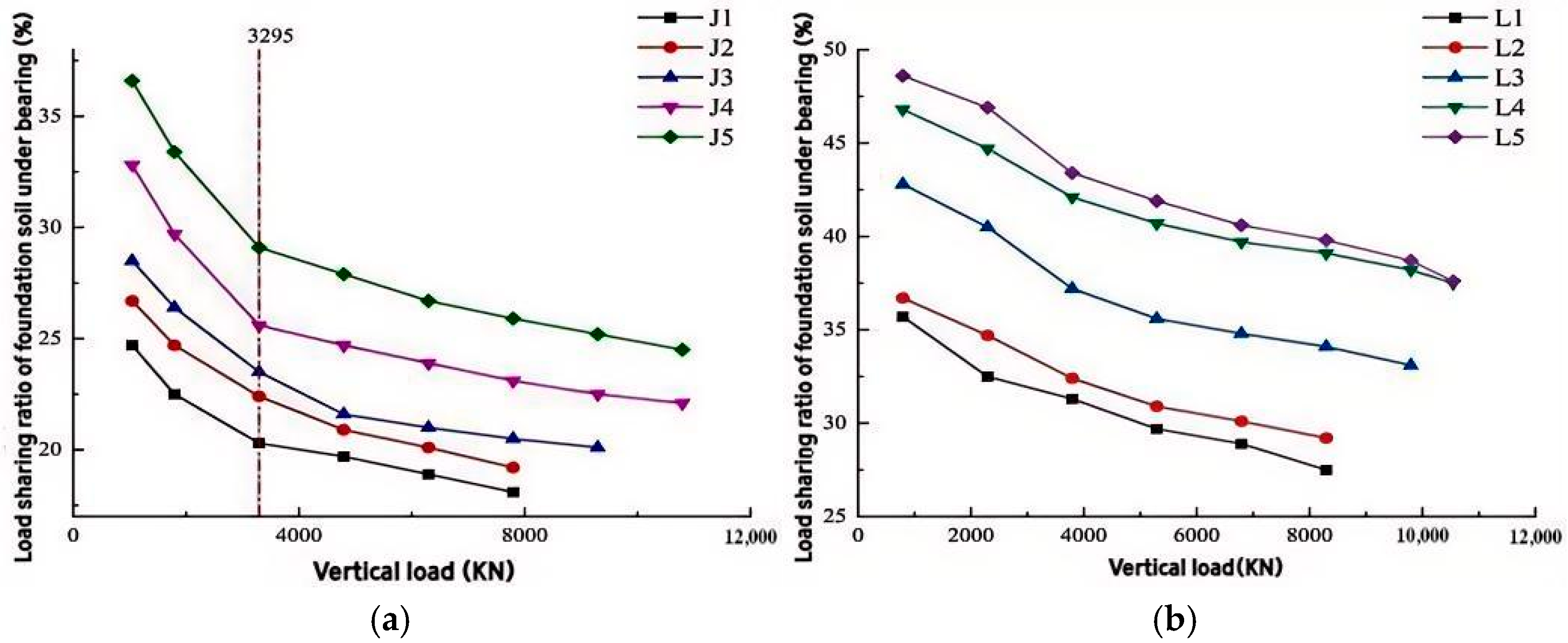
3.4. Analysis of Foundation Soil Under the Bearing

Different pile spacings will cause changes in the stress distribution and deformation characteristics of the foundation soil under vertical load. When the pile spacing is small, the interaction between adjacent piles is more significant, and the stress concentration of the foundation soil beneath the piles is more pronounced. This leads to an increase in the load borne by the foundation soil. Conversely, when the pile spacing is large, the influence of each pile on the foundation soil is relatively independent, the bearing capacity of the foundation soil is dispersed, and the load sharing is relatively decreased. Therefore, the variation curve of the load sharing ratio of the foundation soil is plotted, as shown in Figure 12.
As can be observed from Figure 12a, the curve of the load sharing ratio of the foundation soil beneath the pile support shows a gradual decline as the vertical load increases. During the initial phase of loading, the foundation soil underneath the pile cap begins to play its role. Among them, in the J5 pile group model, the foundation soil shares the largest proportion of the load, which can bear nearly 35% of the upper load. With the increase in pile spacing, the proportion of the load shared by the foundation soil under the bearing gradually increases. When the distance between the piles is relatively short, the proportion of the load borne by the foundation soil beneath the bearing undergoes only minor changes. After the load reaches 3294.5 kN, the divergence between the curves of J3 and J4 is greater than that between the curves of J4 and J5. This indicates that, under the J4 model, increasing the pile spacing leads to a decrease in the proportion of the load shared by the foundation soil. There is a reasonable range for the pile spacing to increase the load sharing of the foundation soil under the bearing, that is, the net spacing between the disks is 3.5 to 4 times the disk overhang diameter.
As can be seen from Figure 12b, The variation pattern of the load sharing ratio of the foundation soil beneath the CEP six-pile foundation is largely consistent with that beneath the CEP nine-pile foundation. In both cases, the load sharing ratio of the foundation soil gradually diminishes as the vertical load increases. By comparing the load sharing ratios of the foundation soil under the CEP nine-pile and six-pile foundations under the same loading condition, It has been discovered that the load sharing ratio of the foundation soil beneath the six-pile foundation is greater than that beneath the nine-pile foundation. By comparing L2, L3, and L4, it is found that reducing the distance between the front and back piles will decrease the load sharing ratio of the foundation soil under the bearing plate, while increasing the distance between the front and back piles will enhance the bearing capacity of the foundation soil under the bearing plate.

4. Conclusions

By analyzing the characteristics of the curve, the deformation of the soil surrounding the pile can be determined based on the initial linear relationship transitioning into non-linear behavior as the load increases. Subsequently, the curve exhibits a pronounced steep drop section. Through the analysis of the slope changes in the curve, turning points, and the soil displacement cloud map around the pile, the bearing capacity and initial stiffness of the pile are evaluated.
Through the research on the compressive failure mechanism and bearing performance of the NT-CEP pile group under different pile spacings, the following conclusions are drawn:
(1) The analysis indicates that the soil surrounding the pile developed a continuous sliding surface, subjecting the pile body to significant lateral earth pressure. In this scenario, the cooperative interaction between the pile and soil primarily manifests as the pile body resisting the sliding tendency of the soil mass through frictional forces and end resistance, thereby restricting soil deformation. Simultaneously, the reactive force from the soil mass acts on the pile body, inducing specific displacements and internal forces within the pile. Additionally, the compressive bearing capacity of the pile group increases with an increase in pile spacing. When the pile spacing is small, the pile group effect is significant. When the pile spacing is increased to more than four times the spiral diameter, further increasing the pile spacing has a negligible effect on the enhancement of the bearing capacity. In practical engineering, it is advisable to control the pile spacing at 3 to 4 times the overhang diameter of the disk.
(2) An increase in the pile spacing not only boosts the vertical bearing capacity of the central pile but also raises the lateral friction resistance of the corner pile. Moreover, it facilitates a proper load-sharing ratio between the bearing disk and the pile end.
(3) For both the CEP six-pile foundation and the CEP nine-pile foundation, an increase in the pile spacing is capable of raising the proportion of the load that the foundation soil beneath the support shares. If the inter-pile distance in the same row of the six-pile foundation is kept constant and the distance between the front and back piles is increased, both the vertical bearing capacity and the bearing ratio of the foundation soil can be enhanced. For the nine-pile foundation, it is more suitable to set the clear distance between the ends of the plates to 3.5 to 4 times the overhang diameter. Under limited site conditions, the overall bearing performance of the six-pile foundation can be improved by increasing the distance between the front and back piles.
This paper deeply evaluates the impact of pile spacing on the compressive bearing capacity of NT-CEP pile groups. It also proposes the most suitable ratio between the net distance at the pile ends and the overhang diameter of the pile plates in NT-CEP pile groups. This offers a reference for ascertaining the reduction coefficient and the calculation model of the compressive bearing capacity of NT-CEP pile groups in relation to various pile spacings.

Author Contributions

Conceptualization, Y.Q.; Methodology, Z.M.; Software, H.Y.; Validation, W.T. and M.G.; Formal analysis, H.L.; Investigation, H.L.; Resources, M.G. and Z.M.; Data curation, H.Y.; Writing—original draft, H.L.; Visualization, H.Y. and Y.Z.; Supervision, Y.Q.; Project administration, W.T. and Y.Z.; Funding acquisition, Y.Z. All authors have read and agreed to the published version of the manuscript.

Funding

This study was supported by the Scientific Programs of the National Natural Fund (Grant No. 52078239).

Data Availability Statement

The data supporting the results of this study are included within the manuscript.

Acknowledgments

The authors would like to thank the experts for providing valuable comments on the experimental part of this paper.

Conflicts of Interest

Author Wei Tian was employed by the company Yanji Branch of Jilin Expressway Group Co., Ltd. Authors Yingtao Zhang, Ming Guan and Zhongwei Ma were employed by the company China Construction Fifth Engineering Bureau Co., Ltd. The remaining authors declare that the research was conducted in the absence of any commercial or financial relationships that could be construed as a potential conflict of interest.

References

  1. Ma, H.-W.; Wu, Y.-Y.; Tong, Y.; Jiang, X.-Q. Research on bearing theory of squeezed branch pile. Adv. Civ. Eng. 2020, 2020, 6637261. [Google Scholar] [CrossRef]
  2. Zhang, M.; Xu, P.; Cui, W.; Gao, Y. Bearing behavior and failure mechanism of squeezed branch piles. J. Rock Mech. Geotech. Eng. 2018, 10, 935–946. [Google Scholar] [CrossRef]
  3. Gao, X.-J.; Wang, J.-C.; Zhu, X.-R. Static load test and load transfer mechanism study of squeezed branch and plate pile in collapsible loess foundation. J. Zhejiang Univ.-Sci. A 2007, 8, 1110–1117. [Google Scholar] [CrossRef]
  4. Ju, Y.; Chen, Y.F. Experimental study for the bearing capacity calculation of concrete expanded plates in squeezed branch piles. Mater. Test. 2018, 60, 1118–1124. [Google Scholar] [CrossRef]
  5. Tang, S.T.; Chen, L.H. Field test of dx pile group. Adv. Mater. Res. 2011, 243–249, 2451–2455. [Google Scholar] [CrossRef]
  6. Do, D.H.; Pham, T.A. Investigation of performance of soil-cement pile in support of foundation systems for high-rise buildings. Civ. Eng. J. 2018, 4, 266–277. [Google Scholar] [CrossRef]
  7. Wang, H.; Ran, Z.; Yan, J. Design and application of expanded pile in bridge super-large diameter pile foundation. Jiangxi Build. Mater. 2022, 187–189+192. [Google Scholar]
  8. Wang, H.; Jin, X. Application of construction technology of super-large variable diameter consolidated disc expanding pile in confined space under silty sand geology. Eng. Constr. Des. 2022, 7, 144–146. [Google Scholar]
  9. Brown, D.A.; Morrison, C.; Reese, L.C. Lateral load behavior of pile group in sand. J. Geotech. Eng. 1988, 114, 1261–1276. [Google Scholar] [CrossRef]
  10. Hadi, D.H.; Waheed, M.Q.; Fattah, M.Y. Effect of Pile’s Number on the Behavior of Piled Raft Foundation. Eng. Technol. J. 2021, 39, 1080–1091. [Google Scholar] [CrossRef]
  11. Fattah, M.Y.; Al-Obaydi, M.A.; Al-Jalabi, F.A. Effect of number of piles on load sharing in piled raft foundation system in saturated gypseous soil. Int. J. Civ. Eng. Technol. (IJCIET) 2018, 9, 932–944. [Google Scholar]
  12. Al-Suhaily, A.S.; Abood, A.S.; Fattah, M.Y. Bearing capacity of uplift piles with end gates. In Proceedings of China-Europe Conference on Geotechnical Engineering: Volume 2; Springer International Publishing: Berlin/Heidelberg, Germany, 2018; pp. 893–897. [Google Scholar]
  13. Qian, Y.; Dong, Y.; Tian, W.; Jin, Y. Theoretical Analysis on the Influence of the Slope Angle of Plate for the Failure Mechanism of the Concrete Expanded-Plates Pile Applied for Oceanographic Engineering under the Horizontal Force. J. Coast. Res. 2019, 98, 10–13. [Google Scholar] [CrossRef]
  14. Qian, Y.; Cheng, Q.; Tian, W.; Xu, G. Field test study on compressive failure mechanism of concrete dish-expanded pile with large proportion of half-sided pile. Ind. Archit. 2015, 45, 120–123+130. [Google Scholar]
  15. Yu, H.; Qian, Y.; Niu, L.; Li, Z. Study on the effect of disc cantilever diameter on the uplift bearing performance of double piles of concrete expanded pile. Build. Struct. 2023, 53, 147–151. [Google Scholar] [CrossRef]
  16. Qian, Y.; Zhai, R. Analysis of the Effect of the Space of the Bearing Plate on the Uplift Bearing Capacity of the Concrete Plates-expanded Pile. Open Civ. Eng. J. 2015, 9, 610–615. [Google Scholar] [CrossRef]
  17. Zhu, H.T. Application of reinforced concrete element SOLID65 in ANSYS software. Heilongjiang Sci. Technol. Inf. 2008, 143+269. [Google Scholar]
  18. Lv, T.; Zhao, J.; Xue, L. The Influence of Modeling Methods on the Meshing when Solid Element Was Used in ANSYS—Taking the Design by Analysis of Dry Welding Experiment Module as an Example. Appl. Mech. Mater. 2010, 42, 232–235. [Google Scholar] [CrossRef]
  19. Xing, J.; Li, J. The modeling method and the mesh division of the ANSYS. China Water Transp. (Acad.) 2014, 10, 116–118. [Google Scholar]
  20. Song, Y.J.; Hu, W.; Wang, D.S. Analysis of compacted pile squeezing effect based on modified Cambridge model. Rock Soil Mech. 2011, 32, 811–814. [Google Scholar]
  21. Li, Q.L. Research on Meshing Methods in ANSYS. J. Shanghai Dianji Univ. 2006, 28–30. [Google Scholar]
Figure 1. Model diagram and model pile diagram.
Buildings 15 01404 g001
Figure 2. Grid division. (a) Grid division of pile foundation and soil; (b) Bearing disk local encryption.
Buildings 15 01404 g002
Figure 3. Vertical load-top displacement curves of six piles and nine piles under different loads. (a) Six piles; (b) Nine piles.
Buildings 15 01404 g003
Figure 4. Curve of top displacement reduction rate of nine piles.
Buildings 15 01404 g004
Figure 5. Soil displacement cloud map of front pile section. (a) L1; (b) L2; (c) L3; (d) L4.
Buildings 15 01404 g005
Figure 6. I-I displacement cloud image of J4 J5 section. (a) J4; (b) J5.
Buildings 15 01404 g006
Figure 7. Iii-iii displacement cloud image of J1-J5 section. (a) J4; (b) J5.
Buildings 15 01404 g007
Figure 8. Axial force variation curve of L3 corner pile and side middle pile along pile depth. (a) Corner piles; (b) Side center piles.
Buildings 15 01404 g008
Figure 9. Axial force variation curve of L4 corner pile and side middle pile along pile depth. (a) Corner piles; (b) Side center piles.
Buildings 15 01404 g009
Figure 10. Change curve of axial force of J4 corner pile and center pile along pile depth. (a) Corner piles; (b) Side center piles.
Buildings 15 01404 g010
Figure 11. Change curve of axial force of J5 corner pile and center pile along pile depth. (a) Corner piles; (b) Side center piles.
Buildings 15 01404 g011
Figure 12. Change curve of load sharing ratio of six piles and nine piles under foundation pile bearing. (a) Six piles; (b) Nine piles.
Buildings 15 01404 g012
Table 1. Property parameters of simulated pile–soil.
MaterialsDensity (t/mm3)Modulus of Elasticity (MPa)Poisson’s RatioCohesion (MPa)Friction Angle (°)Pile–Soil Friction Coefficient
concrete2.25 × 10−93.465 × 1040.2----0.3
clay1.488 × 10−9250.350.0435510.7
Disclaimer/Publisher’s Note: The statements, opinions and data contained in all publications are solely those of the individual author(s) and contributor(s) and not of MDPI and/or the editor(s). MDPI and/or the editor(s) disclaim responsibility for any injury to people or property resulting from any ideas, methods, instructions or products referred to in the content.

