Article

Evaluation of the Buttress System of a Great Ottoman Mosque Against Gravity Loads and Horizontal Seismic Forces: The Case of the Istanbul Süleymaniye Mosque

by
Rabia İzol
1,*,
Muhammet Arif Gürel
2,
Çağrı Mollamahmutoğlu
3 and
Fatih Avcil
4
1
Department of Civil Engineering, Istanbul Technical University, Istanbul 34467, Türkiye
2
Department of Civil Engineering, Harran University, Şanlıurfa 63040, Türkiye
3
Department of Civil Engineering, Yıldız Technical University, Istanbul 34349, Türkiye
4
Department of Civil Engineering, Bitlis Eren University, Bitlis 13100, Türkiye
*
Author to whom correspondence should be addressed.
Buildings 2025, 15(8), 1360; https://doi.org/10.3390/buildings15081360
Submission received: 18 March 2025 / Revised: 8 April 2025 / Accepted: 16 April 2025 / Published: 19 April 2025
(This article belongs to the Special Issue Buildings and Infrastructures under Natural Hazards)

Abstract

Historical mosques are some of the most valuable structures in Islamic societies. It is of primary importance to protect these structures and ensure their safe transmission to future generations. This study investigates the adequacy of the buttress system of the Süleymaniye Mosque in Istanbul, regarded as the ‘symbol structure of Ottoman Architecture’, against gravity and horizontal earthquake loads. Although several structural studies have been conducted on this unique building, the absence of any research on the buttress system, which clearly plays a significant role in its survival through many earthquakes, served as the main motivation for this study. After presenting the material properties, a finite element model of the structure was created. Finite element models were also developed for two hypothetical scenarios in which the outer depths of the buttresses were reduced by fifty percent or eliminated. The models and all analyses were performed using ABAQUS software. Gravity load analyses indicated that the mosque does not face any issues related to stresses or displacements. Nonlinear static analyses revealed that, with the current buttress dimensions, the structure can resist horizontal loads up to about 70% of self-weight along the Qibla axis and about 90% along the axis perpendicular to the Qibla. These findings are some of the most significant results obtained thus far in studies investigating the horizontal earthquake resistance of the mosque. Through performance analyses, it was determined that the structure can meet the limited damage performance criterion only with the current buttress depths; however, it cannot satisfy this performance level with reduced buttress dimensions. In conclusion, the study demonstrated that the buttress system of the Süleymaniye Mosque is highly effective against gravity loads and transverse seismic forces and that it was designed not only with practical experience but also with a solid understanding of structural behavior.

1. Introduction

Some examples of religious architecture are among the greatest works of mankind. Egyptian and Greek temples, Romanesque and Gothic cathedrals, and Ottoman Selatin mosques can be given as examples of these works. Mosques built by sultans or their family members are called “Selatin Mosques”. The word “Selatin” is the plural of the word “Sultan” and it means “Sultan Mosque”. These mosques generally have features such as being large, having more than one minaret, and having a sultan’s mahfil (gathering place). Bursa Ulu Mosque, Istanbul Süleymaniye Mosque, and Edirne Selimiye Mosque are the first examples that come to mind for these structures. Like other cultural assets, these structures must be preserved and transferred to future generations safely. For this reason, it is of great importance to examine and determine the resistance of these special structures against vertical and lateral loads.
Süleymaniye Mosque (hereafter often referred to as ‘Süleymaniye’, ‘mosque’ or ‘structure’), which is a part of the Sülemaniye Complex (Külliye), is the largest Selatin mosque, shown in Figure 1. It is located in Istanbul and was built by the famous Ottoman Sultan Süleyman the Magnificent between 1550 and 1557, by Mimar (Architect) Sinan, the great architect, and engineer of the time. The structure is one of the priceless jewels of Turkish-Ottoman architecture [1,2,3]. The architectural features of the mosque will not be mentioned here. Detailed information on this subject can be found in the literature [4,5].
The safety of masonry structures with high walls, covered with vaults or domes, or having arches against both vertical and horizontal forces is closely related to the existence and adequacy of the buttress system of these structures [7,8,9,10,11]. The ancient builders were generally well aware of this, and thus they made and realized designs that amaze us even today. Great Gothic cathedrals, many great churches, and Ottoman Selatin mosques are concrete examples of this awareness. However, some structures such as classical Greek temples were weak against the effects of earthquakes because they did not have a buttress system, and many of them were severely damaged over time, and some even completely collapsed. Forms of buttresses in masonry buildings, previous studies on masonry buttresses, and various issues that remain still to be explored regarding these elements can be found in [12].
The famous Hagia Sophia in Istanbul, with its splendor and dimensions, affected the Ottoman sultans and architects as well as everyone else. However, this structure had some significant inadequacies and therefore suffered great damage in earthquakes. The principal inadequacy of the structure is that the main dome is supported by half domes in the direction of one main axis (east–west), but there is an absence of these half domes in the other main direction (north–south) and the design of the buttress system in this direction is insufficient. Mimar Sinan realized this deficiency of the structure and added new buttresses to it. Thus, he increased its lateral rigidity and stopped to a great extent the displacements caused by the heavy dome of the structure pushing the load-carrying system to the sides. This buttress addition application also rendered the structure safer against earthquakes. Some Ottoman architects, who took Hagia Sophia as their role model, unfortunately repeated its faults in a few mosques they built. Istanbul Bayezid Mosque is an example of this. However, the mistakes in Hagia Sophia are not seen in the Süleymaniye and Kılıç Ali Pasha Mosques, which are the two mosques of Mimar Sinan, whose similarities to Hagia Sophia are emphasized the most. Because, as mentioned above, Sinan himself already noticed the deficiencies in the structural system of Hagia Sophia and tried to improve them. If the subject is handled specifically for the Süleymaniye since it is closer dimensions to Hagia Sophia, it is stated that the structural system in this mosque was formed by Sinan in a much more rational way and a stronger buttress system was established [4,13].
Given the significant vulnerability of historic masonry structures to seismic events, the necessity for their effective protection becomes evident. In seismically active countries such as Türkiye and Italy, numerous heritage buildings have sustained considerable damage over time, underscoring the critical importance of accurate structural assessment and continuous monitoring strategies [14,15].
There are also many studies in the literature on static and seismic safety, risk reliability assessment, nonlinear analysis, and strengthening of various masonry structures such as mosques, churches, minarets, and towers [16,17,18,19,20,21].
This study aims mainly to determine the adequacy of the buttress system of the Süleymaniye Mosque against gravity (vertical) and horizontal earthquake loads. Previous studies on the Süleymaniye Mosque have generally focused either on its overall structural behavior or on specific elements such as its domes, arches, or walls. However, the buttress system of the building has not been specifically studied, despite its vital importance. Therefore, this study aims to investigate in detail the adequacy of the buttress system of the mosque. Considering the high seismic risk of Istanbul, it is clear that a comprehensive assessment of all structural components of highly valued architectural and cultural heritage structures such as the Süleymaniye is of great importance. In this context, firstly, a literature review of the previous studies on the mosque is conducted. Then, the main structural and material properties of the structure are given and the material model used is explained. Next, the finite element model created for the structure is presented and the analysis method used for nonlinear analyses is explained. Afterwards, for the structure, firstly linear analysis under gravity loads and then nonlinear static analyses under horizontal earthquake loads are performed and the findings are discussed. Performance analyses of the structure are also implemented. The study is concluded with the presentation of the results obtained.

2. Previous Studies on the Süleymaniye

Of course, a lot of work has been performed on the architectural and artistic features of an invaluable building like the Süleymaniye, as well as the great architect Sinan, who designed and built it. But these studies will not be mentioned here. Here, only the major and direct related studies on the static and dynamic structural behavior, material, and foundation properties of the structure will be reviewed. Arıoğlu and Anadol [22] conducted one of the first noteworthy studies on the earthquake resistance of the Süleymaniye. They analyzed and discussed the successful earthquake response of the structure regarding the function of its structural and dynamic characteristics. At the end of the study, it was emphasized that the good resistance of the mosque against earthquake forces was not a coincidence, but the result of a great intuition and mathematical understanding. Aksoy [23], in his PhD thesis titled “Foundation Systems Applied in Historical Buildings in Istanbul”, dealt with the foundation system of the Süleymaniye Mosque as well. In the work, it is stated that the building has a solid foundation system; there are wide encasements in the foundations of the main walls and piers (elephant legs), while there are narrower encasements in the foundations of the courtyard walls. The author also gives various drawings for all these in his work. Selahiye et al. [24] determined the natural vibration frequencies and mode shapes of the Süleymaniye by both finite element analysis and ambient vibration tests in order to determine the earthquake behavior and performance of the structure. As another step, these dynamic features were determined by processing the data of a small-intensity earthquake recorded in 1994 by nine accelerometers mounted in some parts of the mosque. They observed a satisfactory correlation between analytical and experimental results. Kaya, in her master’s thesis [25], aimed to determine the earthquake performance and dynamic properties of Süleymaniye. In this direction, she first refined the previously prepared three-dimensional finite element model of the mosque. Then, non-destructive tests were conducted to determine the material properties. Moreover, she examined the effects of both material properties and different boundary conditions on the results. In the study, earthquake records obtained from strong motion accelerometers previously placed on the structure were also analyzed and natural frequencies were obtained and these values were compared with those obtained by other methods. As a last stage of her study, an analysis of the improved model of the mosque under a scenario earthquake for Istanbul was performed. Çelik [2], in her PhD thesis, in which she investigated the construction process of the Süleymaniye Complex in the light of available documents, besides other issues, discussed also the materials used in the Süleymaniye Mosque. The author mentioned the “Küfeki stone” (limestone), which forms a large part of the body of the structure, and all the other stones and materials (bricks, metals, woods, glasses, etc.) used in the structure. Fahjan [26] investigated the effects of dome systems on the seismic behavior of Ottoman domed structures in light of the general concepts of modern earthquake engineering. They specifically studied the Fatih and Süleymaniye Mosques, which have different numbers of half-domes, and showed the effect of dome systems on the dynamic behavior of the main structural systems. Şeker [27] carried out very detailed static and dynamic analyses of 28 mosques of Mimar Sinan, including Süleymaniye, in his PhD thesis. In this context, he first gave information about the construction techniques and the materials used and then modeled the mosques in three dimensions and carried out static and dynamic analyses on these models. Depending on the analyses, the effects of many proportions such as total window area/total wall area, arch thickness/arch opening, area of bearing parts on plan/whole area, elephant leg (pier) area/bearing area on the plan on the system behavior were also examined. In the study, it was concluded that the mosques of Sinan generally have good resistance to both vertical (gravity) and seismic loads. Aslan [28], in his master’s thesis, examined the behavior of the Süleymaniye Mosque under different earthquake records and depending on local soil conditions. He modeled the structure in SAP2000 software and used the macro-modeling technique to model the texture of the structure. As a result of the analyses carried out in the study, the behavior of the structure for different earthquake effects was obtained. In addition, the areas of the structure most affected by earthquakes were determined, and its behavior depending on the resulting stresses and displacements was assessed. Akyürek et al. [29] analyzed Mimar Sinan’s contributions to the art of structural engineering and analyzed the design principles of his mosques through the relationship between geometry, form, and structure. They emphasized that Sinan achieved wider, brighter, and more holistic spaces than previous Ottoman mosques, with a unique style based on the dome, a masonry skeleton, and polygonal baldachins. The authors also compared the Süleymaniye and Selimiye mosques, the two largest mosques of Sinan, with famous masonry domed structures such as Hagia Sophia, El Escorial, St. Peter, and St. Paul in terms of various structural features. In the study, the strength, efficiency, and elegance aspects of the Sinan mosques, with regard to the masonry domed constructions, were emphasized with detailed analyses based on drawings and proportional calculations.
There are also many studies in the literature about historical masonry structures other than Süleymaniye. Some studies have addressed the damages that occurred in the structure after the earthquake [30,31,32,33,34]. In addition, the behavior of many historical masonry structures under different loads has been investigated [35,36,37,38,39,40,41,42].
From the dimensions of its main bearing elements and some studies mentioned above, it is understood that Süleymaniye was built quite safely against vertical loads like most historic masonry buildings. According to this fact, no serious structural problem was encountered in it, despite it being nearly five hundred years old. However, Istanbul, where the mosque is located, is a city with high seismicity.
Süleymaniye underwent the most comprehensive restoration in the Turkish Republic’s history between 2007 and 2011. In this context, besides structural consolidation of the domes and minarets of the structure, conservation and similar restoration works were carried out on the damaged calligraphy and drawings [43].
Structural analysis studies on the Süleymaniye Mosque, the main ones of which have been listed above, mostly focused on the general behavior of the structure. However, the buttress system, which plays an important role in keeping the mosque in trouble-free condition under vertical loads and surviving earthquakes without being damaged, has not been specifically examined. For this reason, in this study, the buttress system of the structure is addressed. İzol [11] recently examined the adequacy of the mosque’s buttress system for both vertical loads and horizontal seismic loads by performing gravity load analysis and detailed nonlinear static analyses on the structure in her PhD thesis. The present paper is largely formed from this thesis.

3. Main Structural Features of the Mosque and Its Buttress System

Within the scope of this study, the sufficiency of the buttress system of the Süleymaniye Mosque against gravity loads and horizontal seismic loads has been examined. Therefore, in this section, the main geometric and structural features of the structure are presented without going into excessive detail, and information is given about the buttresses that support its walls.
The mosque consists of two parts, a prayer area and a courtyard, shown in Figure 2. In this study, only the prayer area of the structure was taken into account, only this part was modeled, and all analyses were performed here. This is because it is the main body of the structure, which is covered with domes, carried by large arches, huge piers, thick periphery walls, and propped up by massive buttresses. The area is 64.50 m long in the Qibla direction and 69.30 m in the perpendicular direction. It is covered with a main dome, two half-domes supporting this main dome on the Qibla axis, four smaller (secondary) half-domes supporting these domes, and five smaller domes in each side gallery. The main dome had been buttressed laterally by 12 small flying buttresses and has a diameter of 26.50 m, an average thickness of 0.95 m, and a height of 48.92 m from the ground. The load of the dome is first transferred to four large arches and pendentives, and then to four very large piers (elephant legs). There are also eight columns among the elements that carry the load of the area, four of which are made of monolithic colored stones, and the other four are made of white marble.
Süleymaniye was designed and built as a structure fortified with buttresses, although its walls are quite thick. The southeast (Qibla) wall has six buttresses, all trapezoidal, as seen in Figure 3a. The northwest wall, which faces the courtyard, has four buttresses. These buttresses had been placed on the inside of the wall, to create a smooth wall outer surface, Figure 3b. Each of the northeast and southwest walls had been backed by three buttresses, Figure 3c,d. Two of these buttresses are rectangular, while the one on the Qibla wall side is a two-stepped buttress. At the corners where these northeast and southwest walls intersect with the northwest wall, there are minarets of the mosque with three balconies. Thus, without including the minaret pedestals, the structure has an impressive buttress system consisting of sixteen buttresses. The buttresses, piers, and other main elements of the structure are shown and named in Figure 4. This nomenclature will be used later.
As can be seen from the plan in Figure 4, there is an internal load-carrying system in the central area of the mosque, consisting of four huge piers, four main arches, and a main dome. Each pier has a weight tower on it. This system is called ‘baldachin’. On the other hand, on the periphery, there is an external load-carrying system containing thick walls and buttresses. These two systems are connected to each other by connection arches and iron tie elements. Therefore, the structural system of the Süleymaniye is composed of two subsystems that “work together” [46]. The buttresses have great importance in the formation of this dual system. It is clear that without buttresses, a strong enough external load-carrying system for the structure could not be built with walls alone. This could only be possible by making the walls thicker, which would both make the building bulky and increase material consumption.
As stated, the main purpose of the study is to determine the adequacy of the structure’s buttress system to support it against gravity and horizontal earthquake loads. For this purpose, in addition to the analyses for the present buttress depths of the mosque, analyses were made for the ‘imaginary states’ where the ‘outer’ depths of the buttresses were reduced by 50% and there were no buttresses. Hereinafter, these states will be referred to as PRE-STATE (the present, existing state), FIF-STATE (fifty percent depths state), and NO-STATE (no buttress depths state) in short. What is meant here by the ‘depths’ of the buttresses is their ‘outer dimensions perpendicular to the plane of the wall’. No changes were made to the dimensions of the buttresses parallel to the wall plane. In addition, the protruding parts of the buttresses, on which the arches of the building sit, on the inside of the walls were not touched. Otherwise, in the above-mentioned dual system of the structure, the places where the outer ends of the interconnection arches are supported will remain empty. The dimensions of the buttresses for the above-mentioned cases are given in Table 1.
The findings obtained as a result of the analyses were evaluated and interpreted according to today’s performance criteria and an attempt was made to find out how the Süleymaniye’s buttress system was designed against gravity and horizontal earthquake forces.

4. The Material Model Used and Material Properties of the Structure

In this section, the material modeling method to be used in the analyses and the material properties of the mosque are explained.
There is an expanding body of literature on the investigation of the behavior and modeling of masonry structures under static and dynamic loadings. As it is known, there are two main approaches to modeling masonry structures. These are the ‘micro-modeling’ or ‘bi-material approach’ and the ‘macro-modeling’ or ‘homogenized/equivalent material’ approach [47,48,49]. With micro-modeling, the structural properties of the units (stone or brick) and the mortar themselves are taken, and the finite element discretization follows the actual geometries of these components. Micro-modeling can be implemented in two ways. The first is detailed micro-modeling, where the unit-mortar interfaces are considered potential crack/slip planes, while the wall components are defined separately, as shown in Figure 5a. The second is simplified micro-modeling, represented by repeated extended cellular units interacting at their borders [47,50], as shown in Figure 5b.
On the other hand, the macro-modeling method (Figure 5c) assumes the masonry as a homogeneous continuum, using a finite element mesh that does not necessarily follow the texture, but meets the method’s own criteria. Aiming to produce results at a global level and keeping them at a reasonable level, this modeling approach finds a middle way between accuracy and simplicity [51,52,53].
The choice of modeling method changes in line with the aims of the study. In general, the macro-modeling method is preferred for the calculation of large structures. In this study, the use of the macro-modeling method was preferred because a huge structure such as the Süleymaniye Mosque was examined. Accordingly, homogeneous material properties should be determined for the calculation models of the structure. In the literature, there are some expressions developed to calculate the compressive strength and modulus of elasticity of masonry texture depending on the values of its components. In this study, the expressions presented by Tomaževič [54] were adopted. In this reference, the following relationship based on Eurocode 6 is given to determine the compressive strength of masonry:
f c = K f u 0.65 f m 0.25       ( MPa )
where K is a constant in MPa0.10, between 0.40 and 0.60 depending on the wall structure, and fu and fm are the compressive strengths of unit and mortar. For constant K, the mean value of 0.50 was taken. In the same reference [54], it is stated that the modulus of elasticity E of the masonry texture can be taken in the range 200 fcE ≤ 2000 fc if tests have not been performed to determine it. It was considered reasonable to take the value of E = 1000 fc, which is approximately in the middle of the given range. Moreover, ft = 0.1 fc and ν = 0.20 values, which are frequently used in masonry materials, were taken for the tensile strength and Poisson’s ratio.
Detailed information on the materials used in the Süleymaniye can be found in the study of Çelik [55]. When examined, it is seen that the domes of the structure are generally made of Khorasan bricks, and the other elements are made of stone. As the binder, Khorasan mortar had been used. The columns of the mosque are made of colored and white marble, but the walls and piers, which form a very large portion of its mass, had been built of “Küfeki limestone”. The rationale behind Mimar Sinan’s use of this stone in his works in Istanbul was discussed by Ahunbay [56] and Arioğlu and Arioğlu [57]. In this study, the mechanical and physical properties of the materials used in the Süleymaniye were taken from Şeker [27], Arioğlu and Arioğlu [57], and Korkmaz [58], and are presented in Table 2.
The compressive and tensile strength values and elastic modulus of the parts of the structure consisting of Küfeki stone + Khorasan mortar and Khorasan brick + Khorasan mortar were calculated according to the above expressions and are presented in Table 3. The unit volume weight values of the parts are also given in the table, and they are calculated with the expression:
γ = φ u γ u + φ m γ m + φ v γ v
where φu, φm, φv and γu, γm, γv are the volume fractions and the unit weights of unit (stone or brick), mortar, and voids, respectively. Using the unit weights in Table 2 and assuming reasonable volume fractions such as 75%, 20%, and 5% for unit, mortar, and voids, γ was calculated as 19.70 kN/m3 for Küfeki stone + Khorasan mortar and as 16.79 kN/m3 for Khorasan brick + Khorasan mortar, as seen in Table 3.
In this study, the creation of finite element models of the structure and all analyses were made with the ABAQUS 6.14-5 software [59]. In addition to the above-mentioned properties of the materials, nonlinear behavior of the materials was also taken into account in the nonlinear static analyses. For this purpose, the concrete damaged plasticity (CDP) model in ABAQUS was employed. The CDP model is based on two main fracture mechanisms, crushing under compression and cracking under tension. Since an unreinforced masonry texture is brittle like concrete, the CDP model could be used within this aim. There are many studies in which CDP is used in the nonlinear material definition of masonry structures [60,61].
The development of yield or failure surface is controlled by two hardening variables (Figure 6). These are values for tensile equivalent plastic strain, ε t p l ¯ , and compressive equivalent plastic strain, ε c p l ¯ , associated with the damage mechanism under tension and compression loading (t and c subscripts stand for compression and tension).
The decrease in the modulus of elasticity is taken into account by two damage variables. These are the dt and dc parameters. The parameters take values between 0 and 1. The value of zero represents the undamaged state, and the value of 1 represents the state of complete damage, that is, the state of complete loss of strength. In many studies using the CDP model, the expression d = 1 σ / f has been used in the calculation of the mentioned parameters [53]. In this study, too, this expression was used.
For the axial stress–strain relations of the homogenized materials, the Massicotte [62] model in tension and the Hognestad [63] model in compression were adopted, shown in Figure 7.
The concrete damaged plasticity model assumes potential plastic flow. The potential plastic flow used for the model is based on the Drucker–Prager strength hypothesis. When using the CDP model, other necessary parameters to accurately simulate nonlinear behavior are the angle of dilatation (ψ), the ratio of initial equi-biaxial compressive yield stress to initial uniaxial compressive yield stress (fb0/fc0), yield potential eccentricity (ϵ), and the ratio of the second stress constant on the tensile meridian to the second stress constant on the compressive meridian (Kc) and viscosity parameter (μ). The values used for these parameters in the nonlinear static analysis of the study are given in Table 4. These values were taken in accordance with the values in the ABAQUS user manual [59] and related literature [64,65].

5. Finite Element Model of the Structure

In this section, the three-dimensional finite element model (FEM) created to be used in gravity load analysis and nonlinear static analyses of the Süleymaniye is briefly explained. While forming the FEM for the structure, dimensions were read from the surveys taken from the Istanbul General Directorate of Foundations Archives [66].
Süleymaniye is the largest mosque of Ottoman architecture. Although the structure has a beautiful simplicity, still it contains many details due to its size. The structure is symmetrical in the plan with respect to the Qibla axis and close to symmetrical in the direction perpendicular to the Qibla. Great care was taken to generate a model that could represent the structure as best as possible. While the model was formed in the ABAQUS 6.14-5 software, the mosque was divided into parts and then tied to each other in order to obtain a suitable mesh. Main dome, semi-domes and all small domes, and pendentives were modeled as shell elements. Walls, buttresses, piers, pillars, weight towers, main arches, secondary arches, and all other members were modeled as solid elements. For shell elements S4R type finite element was used and for solids, C3D8R type element was used. A total of 71,831 elements and 107,758 nodes were used in the model. The base of the model was taken as fixed. Minarets and courtyards were not included in the modeling, since it is clear that their effects on the results to be obtained in this study, where the nonlinear analysis method is used as the analysis method, will be small. Moreover, it has been observed that many other researchers [20,21,22] have excluded minarets and courtyards in their mosque models, with similar considerations. Thus, by excluding the minarets and the courtyard, the model was kept simpler and the analyses were made easier. The FEM of the mosque generated in this way is given in Figure 8. Although some simplifications have been made inevitably, it can be said that this model has one of the most refined meshes among the models produced in all the structural studies on the mosque so far. As can be seen from the figure, in the model formed, the z-axis shows the Qibla axis, the x-axis shows the axis perpendicular to the Qibla, as in Figure 2, and the y shows the vertical axis.

6. Analysis Method and Computational Procedure

It is not an easy task to precisely determine the earthquake resistance of a historical masonry structure like the Süleymaniye. The fact that the structure itself is a large multi-element structure, masonry materials exhibit brittle behavior due to their nature, and an earthquake is a very complex event are just a few of the reasons for this.
In this study, the nonlinear static (pushover) analysis method was used as the analysis method to determine the earthquake resistance of the Süleymaniye, both in the direction of Qibla and in the direction perpendicular to it for existing and reduced buttress dimensions. Of course, for this purpose, for example, the time history analysis method could also be used, taking into account a sufficient number of historical real earthquake records and/or synthetic records for the location of the structure. However, the nonlinear static analysis method was preferred because of its simplicity and clearer interpretation of the outputs obtained from it, therefore making it more suitable for the purpose.
The nonlinear static analysis method, as is well-known, is a quasi-static approach. This method allows for a general seismic assessment with reduced calculation volume, time, and cost by either entirely neglecting the dynamic effects of the earthquake or considering them in a semi-static manner. While it is more approximate, the method remains effective, practical, and widely used for evaluating masonry structures [67,68,69]. To be briefly mentioned, in this study, a uniform, unidirectional, mass-proportioned loading pattern was considered when performing nonlinear static analysis on a model of the mosque. The loading was gradually increased until a limit (target, cut-off) displacement value was reached.
The primary objective of the study is to assess the effect of the buttress dimensions (depths) of the Süleymaniye Mosque on both the strength under self-weight and the horizontal earthquake resistance, and thus to find out whether the existing buttress dimensions are sufficient. For this aim, first gravity load analyses and then nonlinear static analyses were performed on both the PRE-STATE model and imaginary FIF-STATE and NO-STATE models of the structure. In the gravity load analyses, the variation in stresses and displacements at various critical points of the structure were examined. On the other hand, in the nonlinear static analyses, the obtained seismic coefficients and capacity curves were compared. After this second group of calculations, performance analyses were also carried out for the structure. With the findings obtained from all these analyses, an attempt has been made to reveal how the changes in the depths of buttresses affect the static behavior, horizontal earthquake resistance, and performance of the structure. In this way, the adequacy of the existing buttress system of the structure has been assessed.
In the study, a quasi-static analysis using the ‘dynamic-explicit method’ was applied to minimize both analysis time and the reliance on high-performance computers. The nonlinear static analyses were conducted in two consecutive numerical steps. In the first step, the models were subjected to self-weights, and in the second step, monotonically increasing lateral loads were gradually applied over very short time intervals. For an acceptable quasi-static analysis, the total load should not be suddenly applied to a model at the beginning of the analysis. Sudden loadings lead to stress waves that can cause deceptive or even wrong results. While performing the analyses, as stable time increments, the value of Δt = 1 × 10⁻⁵ s was used, and for the models, it was constantly checked whether the kinetic energy values remained below 10% of the internal energy values [59] (ABAQUS, 6.14-5).
The outcome of the nonlinear static analysis described above for each model is shown as a capacity curve, specifically the base shear force versus lateral displacement curve for a selected control node. The base shear force was calculated by summing the horizontal reaction forces at the nodal points at the base of the model, and the top point of the main dome of the mosque chosen as the control node. The maximum seismic coefficient, c, which indicates the largest transverse seismic force the model can withstand, was determined as follows:
c = R max / W model
Here, R max and W model denote the maximum base shear force and the weight of the model, respectively.
After these steps in the calculations, the analysis of the model is completed. By comparing the maximum capacities or seismic coefficients obtained for the models, the effect of the depths of buttresses on the horizontal seismic resistance of the structure is determined.

7. Analyses and Interpretation of Results
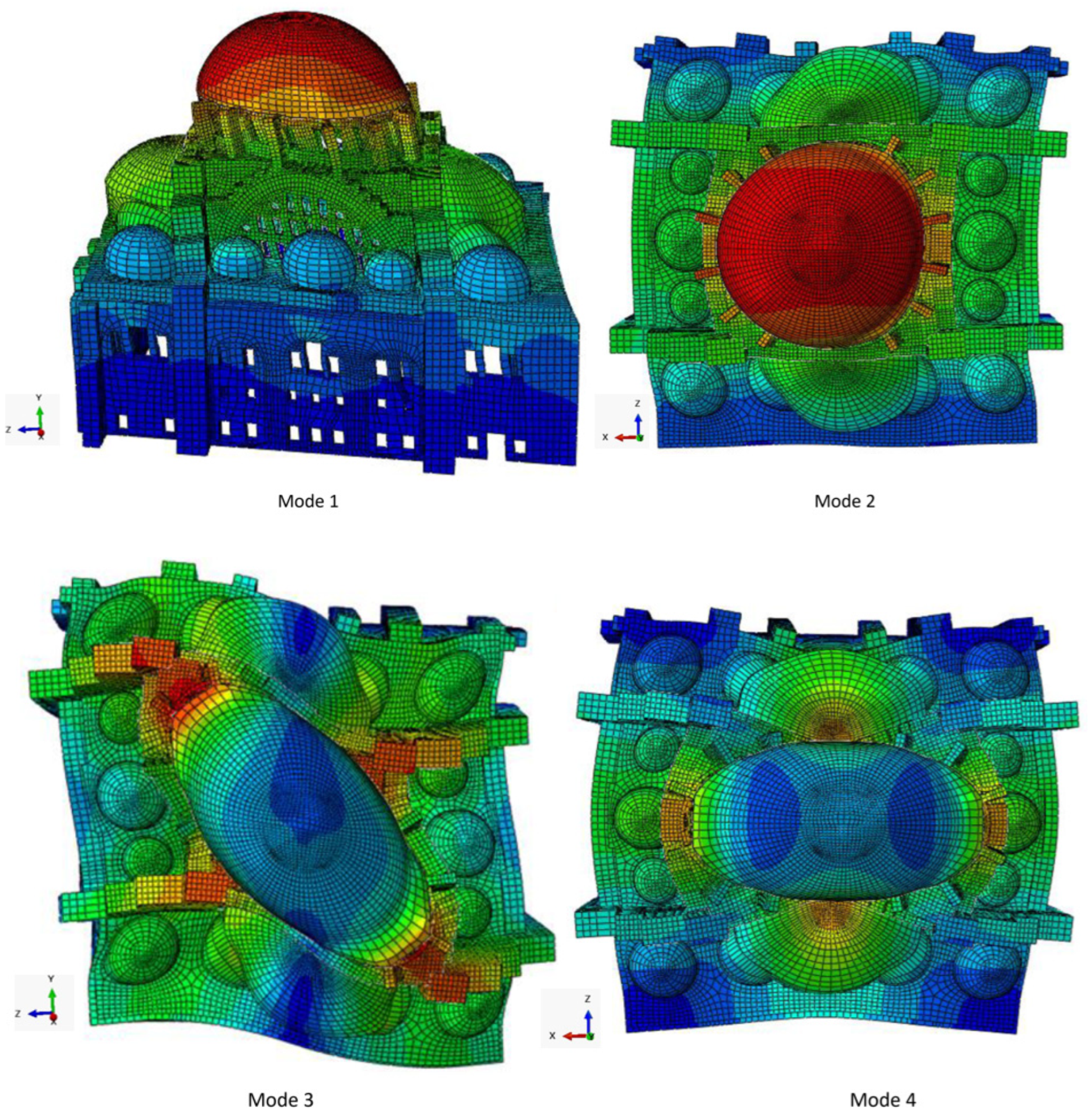
This section constitutes the essence of the study. All analyses intended to be performed on the models of the structure are made in this section and the findings are discussed here. Firstly, the modal analysis was carried out with the present buttress dimensions (PRE-STATE) and the frequencies and mode shapes of the structure were determined. Then, frequency analyses were performed for the imaginary FIF-STATE and NO-STATE of the structure, and an attempt was made to determine how the depths of buttresses affected the modal analysis results. Secondly, under self-weight loading, linear static analyses of the structure’s real and imaginary states were performed, and it was determined how the stresses and displacements in the structure changed depending on the buttress depths. Thirdly, nonlinear static analyses were carried out on three models of the structure, in the direction of each principal axis. Lastly, the findings were compared, and an earthquake performance evaluation of the mosque was made for each state.

7.1. Modal Analysis

The finite element model of the Süleymaniye, obtained using the ABAQUS program, is presented in Figure 8. After the models of the two imaginary states of the structure were also formed, frequency analyses were realized for these three models. Selahiye et al. [24] determined the frequencies and mode shapes of the mosque with both the ambient vibration tests and the placement of the accelerometers. In Table 5, these experimental results are given together with the frequency values obtained for the first four modes with the ABAQUS program. As can be seen, the difference in results is a bit large in the first three modes, but still acceptable. It has been noticed that the differences between them are largely due to the modulus of elasticity we took in the calculations. When the modulus of elasticity is changed gradually, it has been observed that values closer to the experimental results are obtained. As stated in the details of the materials, the mosque has stone and brick parts. It is clear that the modulus of elasticity cannot be the same everywhere in these parts, in a very large structure like the Süleymaniye. Therefore, these reasonable differences between the results are quite normal. For this reason, the modulus of elasticity used for the structure has not been changed in the next calculations. The first four modes of the structure are given in Figure 9.
As a result of the modal analysis, approximately 83% mass participation was obtained within the first 100 modes. Considering the characteristics of historical masonry structures, this level of mass participation can be considered acceptable. The results of the frequency analyses for the first four modes of the three states of the structure are presented in Table 6. As can be seen, the frequency values decrease with decreasing buttress depths. Actually, the decrease in depths leads to a decrease in both mass and lateral stiffness of the structure. It is clear that the effect of this decrease on the stiffness will be greater. Because, while the mass decreases proportionally to the decreasing dimension itself, lateral stiffness decreases proportionally to the cube of that decreasing dimension. Therefore, it is logical and expected that the frequency values of the structure decrease as the depths of the buttresses of the structure decrease. On the other hand, it is also seen from the table that these decreases in frequencies are not so radical. This indicates that the structure already has good horizontal rigidity, even without the outer parts of the buttresses.

7.2. Linear Static Analysis Under Gravity Loads

The occurrence of crushing due to exceedance of the compressive strength of the material is a very rare situation in historical masonry structures. Problems due to tensile stress are also not very common, since the level of this stress mostly had been kept low by the appropriate forms used. However, as in all types of structures, it is important to perform a linear static analysis under self-weight in order to see the stress distribution in these structures. On the other hand, displacement problems caused by sustained loads, support settlement, creep, insufficient rigidity, etc., are more common in such structures. For this reason, it is important to determine the displacements too, with the analysis to be performed, and to control their magnitude.
In this subsection, linear static analyses were performed on the models of the present and two imaginary states of the Süleymaniye under gravity loads, and the stress state and displacements of the structure were determined. As is known, linear analysis considers that the material is linear-elastic and the displacements are very small relative to the dimensions of the structure. In such an analysis, as in any type of structural analysis, the structure develops an internal stress state to balance the loads to which it is subjected.
Linear static analysis results for the PRE-STATE, FIF-STATE, and NO-STATE models of the mosque under self-weight are presented in Figure 10, Figure 11 and Figure 12. Looking at the figures, it is seen that there is no prominent change in the stress distribution and displacements of the structure with the decrease in the buttress depths. Some points of the structure have been selected in order to clearly see the change in the stress and displacement state of the structure. The naming of these points is given in Table 7, and their locations are shown in Figure 4 and Figure 13. The vertical stress values of the points considered are presented in Table 8 and the vertical/horizontal displacement values of the selected points are given in Table 9.
For a masonry structure whose walls are fortified by buttresses and has a covering system of substantial weight, if weaker buttress systems are devised, the behavior to be expected from that structure will be the further opening of the structure to the sides. From the values in Table 8 and Table 9, it is seen that this behavior is also observed in the analyses performed for the Süleymaniye under self-weight. Let us start the discussion by looking at the stresses in the P1 pier. The weaker the buttress system of the structure, the more this pier will be pushed towards the corner near it (the corner where the buttresses QB1 and SWB1 meet, Figure 4). Accordingly, the compressive stress of a point located on an edge far from the pushed corner, whether in the top or bottom cross-section of the pier, decreases, while the compressive stress of a point located on a near edge increases. In Table 4, this is immediately apparent when looking at the variation in the stresses at the selected points B1, B2, T3, and T4 of the pier, seen in Figure 13a.
Now let us move on to the variation in the vertical stresses in the interfaces of the buttresses and walls of the structure. The buttresses chosen for this purpose are the SWB3 buttress on the southwest wall and the QB1, QB2, and QB3 buttresses on the Qibla wall. In the top and bottom sections of the walls to which these buttresses belong, the vertical stresses at the midpoints of the buttress–wall outer interfaces shown in Figure 13 are considered. As seen from Table 8, vertical stresses increased at all points as the buttress depths decreased. The out-of-plane stiffness of a wall with buttresses will of course be different in cases where its buttresses are deep, less deep, or have no depth. A wall having deep enough buttresses will be less stressed by the support of these buttresses, while a wall with weak buttresses or no buttresses will, on the contrary, be more forced. It is therefore normal that stresses increase with decreasing depths of buttresses. Changes in stresses are higher in these points, which are located on the periphery of the structure, than the pier’s points, which are located inside.
If a general assessment is made, the variations in vertical stresses at all considered points of the structure are small, and the stresses are well below the compressive strength value (fc = 8.87 MPa) given in Table 3. Hence, under the self-weight of the structure, there is no problem in terms of stresses.
Displacement distributions for the PRE-STATE, FIF-STATE, and NO-STATE models of the mosque under their self-weight are presented in Figure 10c, Figure 11c and Figure 12c. According to the figures, there is no significant change in the displacements with the reduction in the buttress depths. In order to clearly see the change in displacement state, the displacements of the nine selected points of the structure have been specially examined. The vertical/horizontal displacements of these points, specified in Table 7, for the present and two imaginary states of the structure are given in Table 9. As can be seen from the table, the displacements of all points are very small for the present state of the structure, and little changes occur in these displacements as the depths of the buttresses decrease. As noted above when examining the stresses, this is because the mosque has four piers of very large cross-section and thick enclosing walls.
It has been seen that the displacements that occur under the self-weight of the structure are so small that they can be neglected compared to the dimensions of the structure. The structure also has no problem in terms of displacements. Therefore, the analyses performed in this subsection show that the Süleymaniye is a structure that is safe under self-weight in terms of both stresses and displacements.

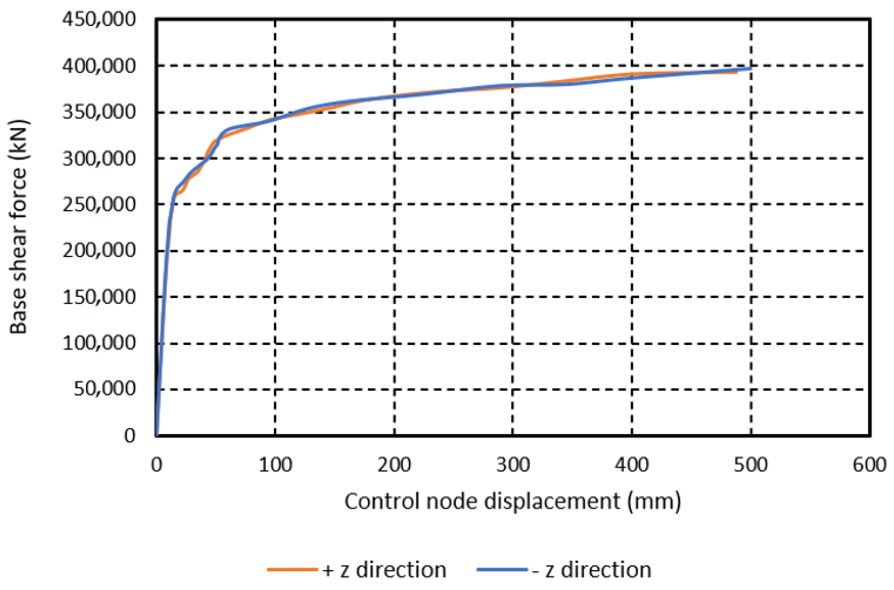
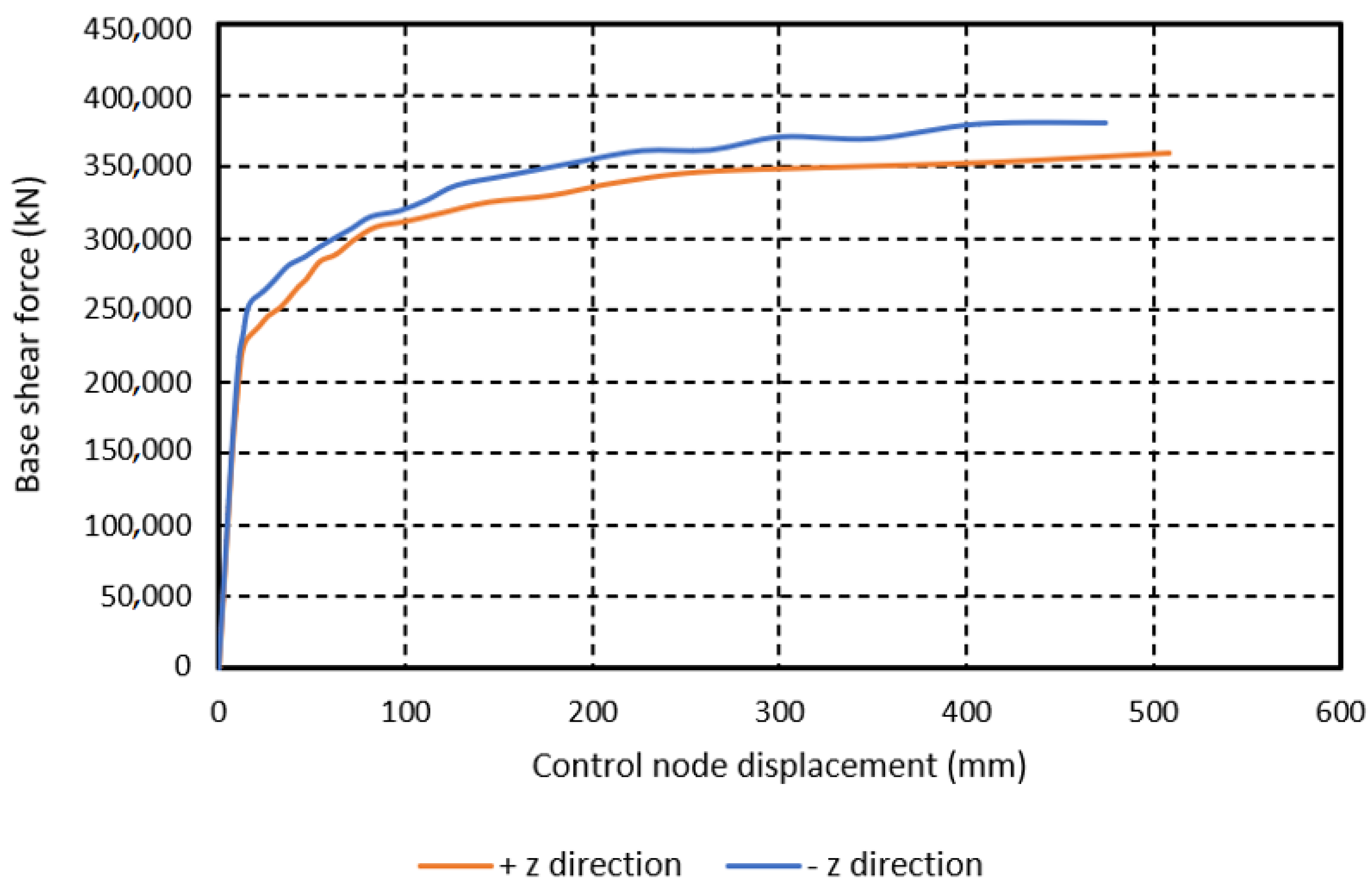
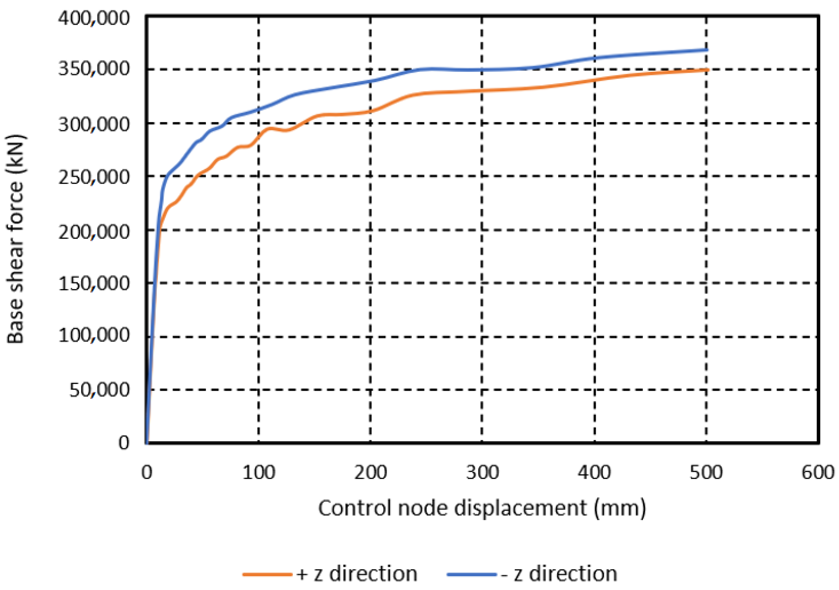
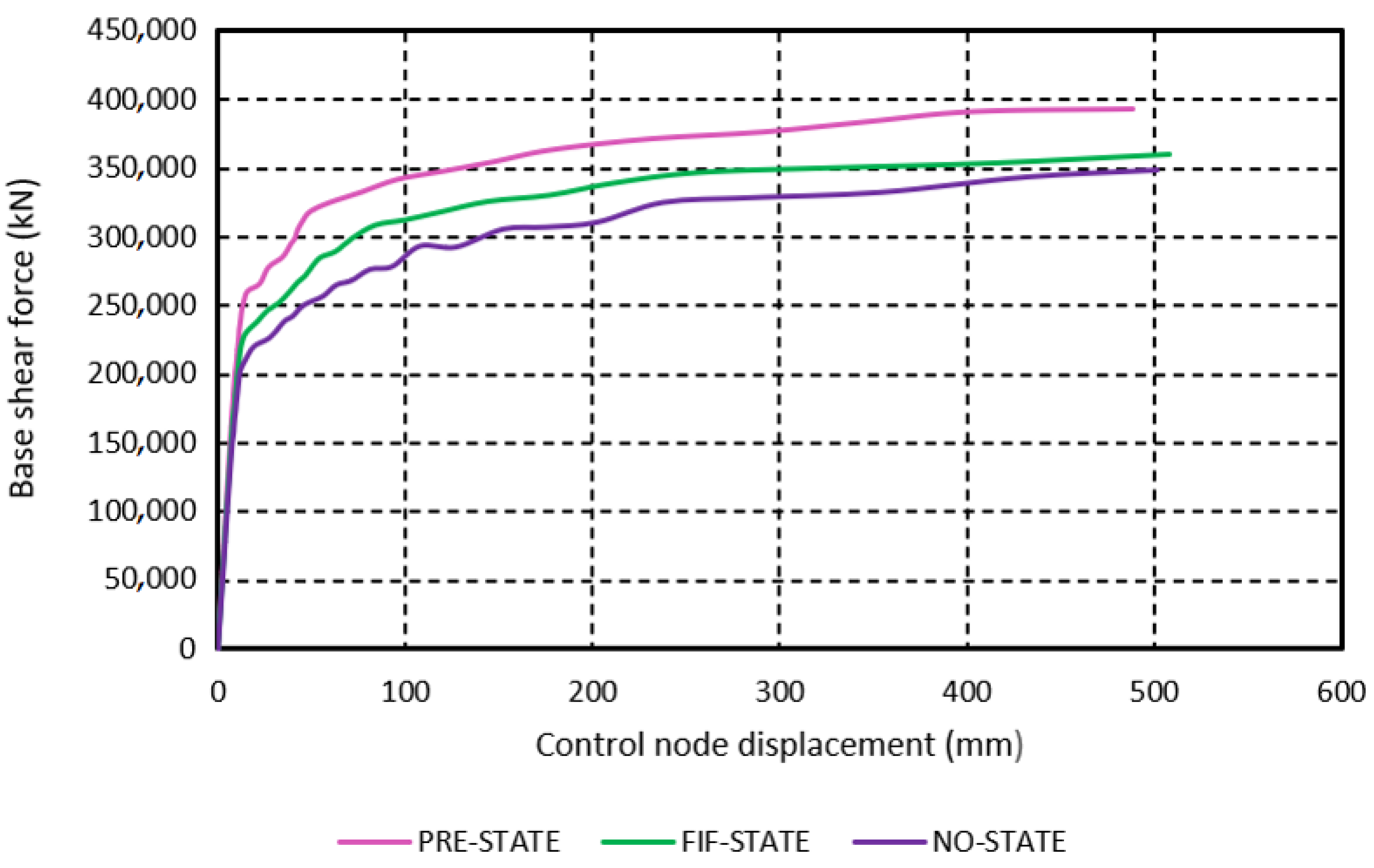
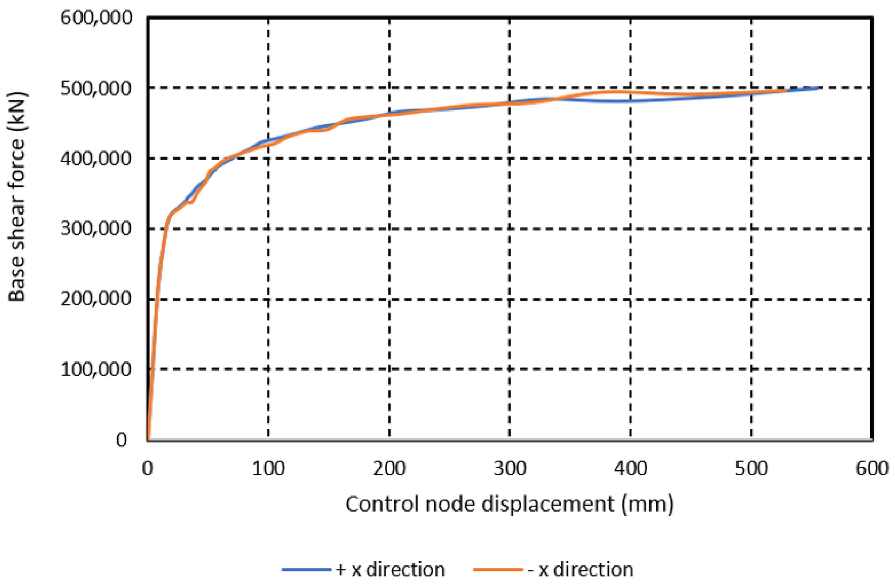
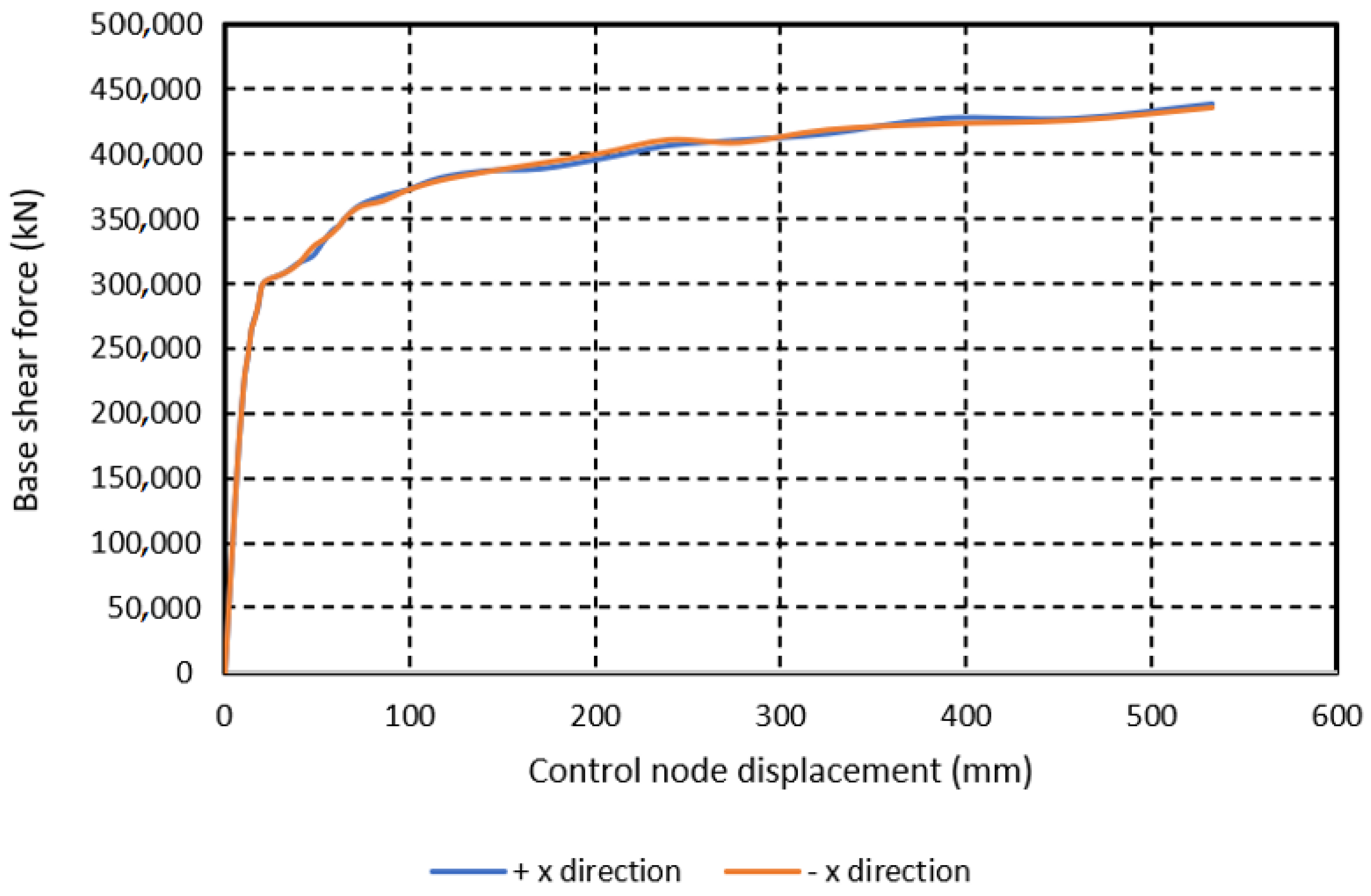
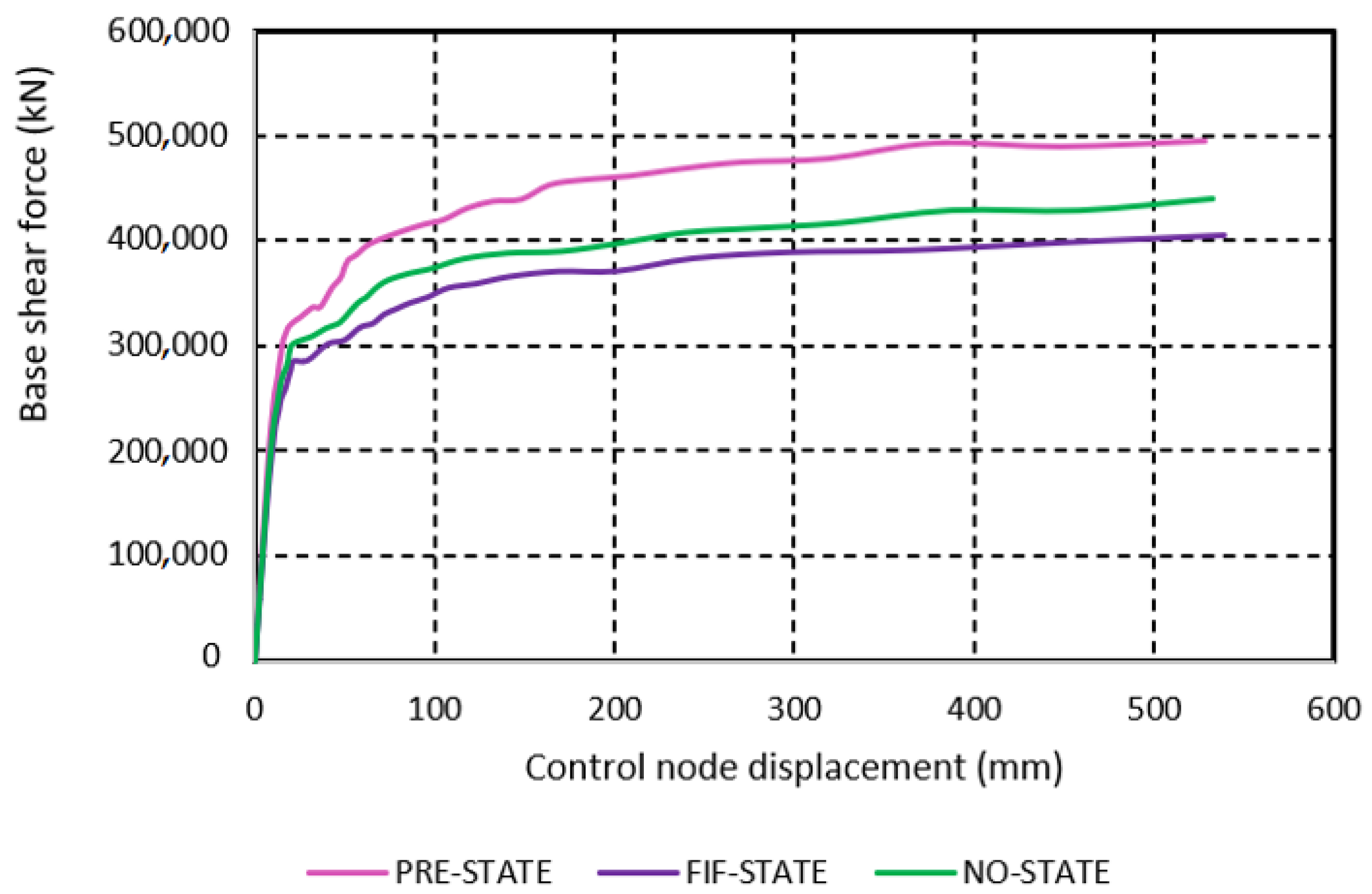
7.3. Nonlinear Static Analyses

The purpose of the analyses made in this subsection is to determine how the Süleymaniye Mosque’s buttress dimensions (depths) affect its horizontal earthquake resistance. Nonlinear static analyses were performed both on the PRE-STATE model and on the imaginary FIF-STATE and NO-STATE models of the structure. Analyses were carried out in both directions of the two major axes (Qibla axis and axis perpendicular to the Qibla). From each analysis, a base shear force versus control node horizontal displacement graph, i.e., ‘pushover curve’, was obtained. As the ‘control node’, the node on the top of the main dome of the structure was chosen. By evaluating the pushover curves, the effect of buttress depths on the horizontal earthquake resistance of the structure has been tried to be understood.
To perform the nonlinear static analyses, a unidirectional, mass-proportional horizontal loading pattern was considered for the models of the present and two imaginary states of the structure. First, self-weight loading was applied to each model, and then the mentioned horizontal loading was imposed. Horizontal loading was applied in both directions of each major axis. As can be seen from Figure 2, the major axes are the Qibla axis (z axis) and the axis perpendicular to the Qibla (x axis). Hereafter, the axis perpendicular to the Qibla will be called the ‘Per-Qibla axis.
Figure 14, Figure 15 and Figure 16 show the pushover curves of the three models of the mosque for the two directions (+z and −z) on the Qibla axis. The first thing that catches the attention is that while the curves for the two directions are almost coincident in the PRE-STATE model, the curves are not so in the FIF-STATE and NO-STATE models. This situation can be easily explained by considering the plan shape of the structure seen in Figure 2 and Figure 4. From the relevant figures, it is obvious that the mosque has a very balanced plan shape in both axes. If we look at the Qibla axis, which we are currently paying attention to, it is seen that the buttresses on the southeast and northwest walls, located at the ends of this axis, are in a balanced state. Therefore, it is not surprising that almost overlapping curves were obtained as a result of the pushover analyses in the +z and −z directions on the Qibla axis. On the other hand, when the ‘outer depths’ of the buttresses are reduced, the balance of the buttresses between the southeast and northwest walls deteriorates to a certain extent. This is because, as the buttress depths decrease, the southeast wall becomes increasingly weaker, whereas the northwest wall remains unchanged, since in this later one the buttresses are only on the inside face of the wall, so there was no depth reduction in them. For this reason, the curves obtained from the analyses in the +z and −z directions for the imaginary FIF-STATE and NO-STATE models did not overlap. But in these two imaginary cases, why are the curves for the -z direction higher than the curves for the +z direction (Figure 15 and Figure 16)? The reason for this is the large cross-sectional area it has that works under the compression, thanks to the unchanging buttresses on the northwest wall, when the structure is pushed in the −z direction.
For the present and two imaginary states of the mosque, the curves obtained from the pushover analyses on the Qibla axis and in the +z direction are presented together in Figure 17 for comparison. It is seen that the curve of the present state is on the top, as expected, and the curves of the other two states are slightly below it.
The pushover curves for the two directions (+x and −x) in the Per-Qibla axis for the three models of the structure are given in Figure 18, Figure 19 and Figure 20. In each of the models, it is observed that the curves obtained for the two directions almost overlap. As can be seen from the side views of the mosque in Figure 3c,d, there are three buttresses on each of the northeast and southwest walls, two of which are rectangular, and one of which is stepped. The buttresses standing opposite each other on the walls are almost identical, so there is a perfect symmetry between the northeast and southwest walls. This symmetry is maintained even when the buttress depths are reduced. It is therefore quite logical that almost coincident pushover curves were obtained in both directions on the Per-Qibla axis. The pushover curves of the three states are compared in Figure 21 for the case where the structure is pushed from the northeast to the southwest. It can be seen that there is a noticeable decrease in the horizontal earthquake resistance of the structure with the reduction in the buttress depths.
It should be noted once again that a limit (cut-off) value for horizontal displacement of the control node was considered in the pushover analyses performed in this subsection. As the limit value, the 1% drift ratio specified in the Seismic Risks Management Guide for Historical Structures (SRMGHS-2017) [70]—which is the main guide in the seismic evaluation of historical structures in Türkiye—was taken as basis. The selected control node is the top of the main dome, which is the highest point of the mosque body, and this point is 48.92 m above the ground. This value was taken as approximately 50 m, and the analyses were terminated when the horizontal displacement values of 500 mm–550 mm were reached. This can be seen from the pushover curves.
The capacity values (maximum base shear forces) calculated from the pushover analyses performed in two directions on the Qibla and Per-Qibla axes for the current state and two imaginary states of the structure and the seismic coefficients determined by Equation (3) are presented in Table 10. The first thing to notice in the table is that the horizontal resistances for both axes of the mosque are quite high (maximum seismic coefficients) and these are close to each other. As can be seen, with the present buttress system, the structure has a horizontal load carrying capacity of 70% of its weight in the Qibla axis and nearly 90% of its weight in the axis perpendicular to the Qibla. The structure has somewhat higher resistance on the Per-Qibla axis than on the Qibla axis, both in its current state and in its imaginary states. One of the main reasons for this is that each of the NEB2, NEB3, SWB2, and SWB3 buttresses on the northeast and southwest walls has a significant part also on the inner face of the wall (Figure 4), and these parts are not included in the depth reduction. Other important reasons are that the southeast and northwest walls (walls parallel to the Per-Qibla axis) are longer than the northeast and southwest walls (walls parallel to the Qibla axis), and there are relatively fewer openings (windows, etc.) in these walls that weaken the continuity. For the present state of the mosque, the maximum seismic coefficient value, c, obtained for the Per-Qibla axis is about 27% greater than that obtained for the Qibla axis. If there are no parts of the buttresses of the structure that protrude beyond the walls (NO-STATE cases), this value decreases to around 18%.

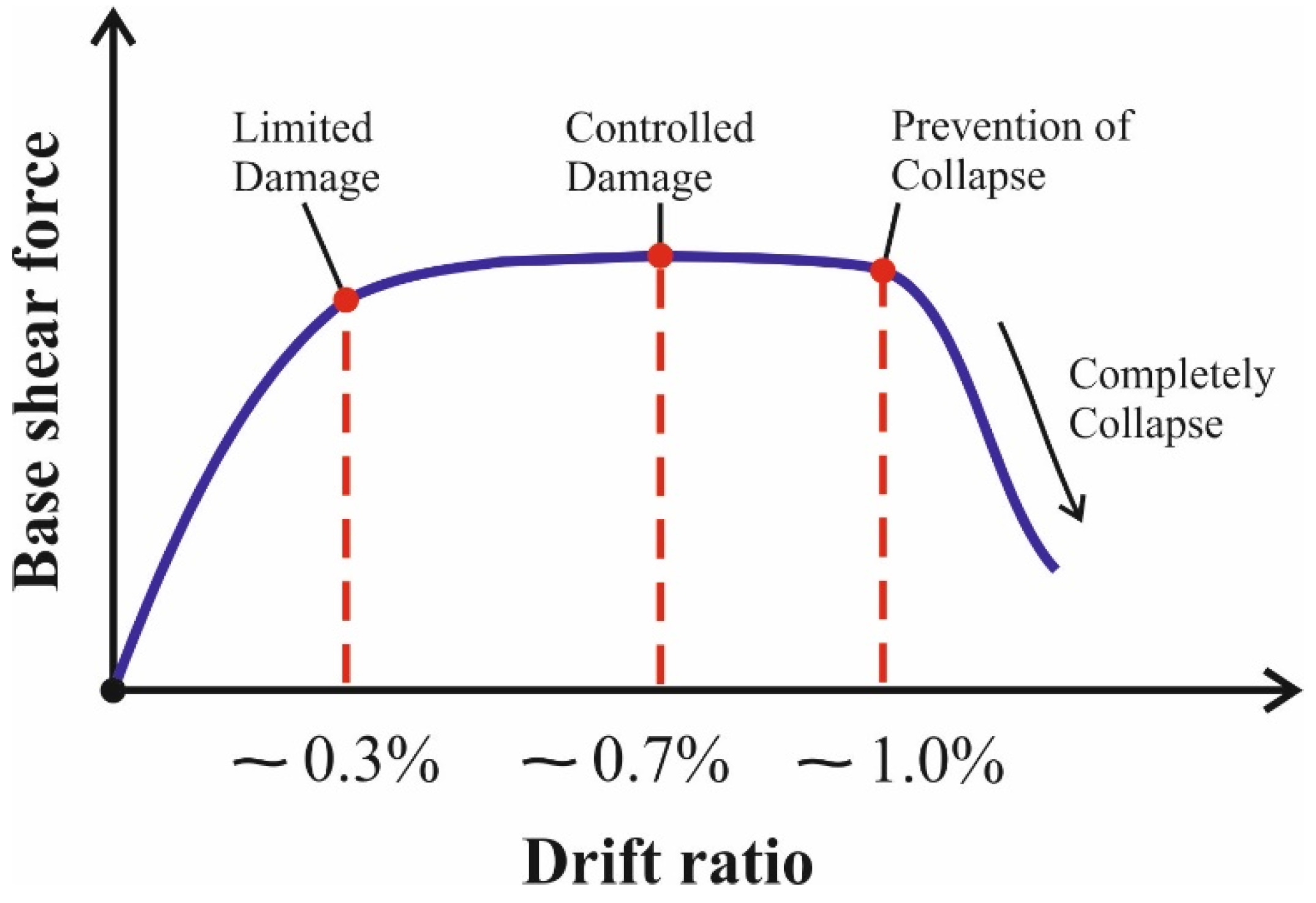
7.4. Performance Evaluation of the Mosque

The structural and earthquake engineering communities have developed a new generation design and evaluation procedure: the performance-based design and evaluation. As is known, this procedure considers that the level of damage and its control are important in the seismic design and evaluation. Detailed information on this subject can be found in various studies; for example, in works by Fajfar [71] and Lagomarsino and Cattari [72]. In this part of the study, the earthquake performance of the Süleymaniye was evaluated. In this evaluation, the capacity curves obtained above were used together with the N2 method of Fajfar [71], which is briefly explained below, and SRMGHS-2017 [70] was taken into account. SRMGHS-2017 [70] is currently the main guideline for seismic evaluation of historic structures in Türkiye. With the evaluations made, the adequacy of the buttress system designed and built for the Süleymaniye in terms of building performance has been questioned and interpreted.
SRMGHS-2017 [70] has defined different performance levels according to the importance of historical buildings. These levels are ‘the limited damage performance level’, ‘the controlled damage performance level’, and ‘the prevention of collapse performance level’, as given and described in Table 11.
The targeted level of damage should be at the lowest level for a historical building of international importance, such as the Süleymaniye Mosque, where large numbers of people enter every day for worship and to visit. Therefore, for the limited damage performance level of the mosque, the horizontal drift ratio should not exceed 0.3%, as shown in Figure 22.
A performance point was determined by evaluating the pushover curves obtained from the analyses of the mosque and the related spectrum curves together. The performance level of the structure was determined by comparing this point with the performance levels in Figure 22. While making the evaluation, the performance point in question was determined by the N2 method proposed by Fajfar (2000) [71] and widely used in the literature. This method is outlined below.
The first step in the N2 method is to determine the elastic acceleration spectrum, SaeT, of the structure according to the relevant regulation. Süleymaniye sits on solid and hard rocky ground [23]. The local soil class is ZA according to Turkish Building Seismic Code 2018 (TBSC-2018) [73]. The elastic acceleration spectrum shown in Figure 23 was obtained for the DD-1 level, which is defined as the largest earthquake ground motion among the four earthquake ground motion levels specified in TBSC-2018 [73], taking into account the mentioned soil class. Using the following expression, this curve was converted to the acceleration–displacement spectrum, SaeSde, shown in Figure 24.
S d e = T 2 4 π 2 S a e
This spectrum curve was transformed to be displayed on the same axis set as the two-line idealized capacity curve using Equations (5) and (6). The transformed curve is given in Figure 25.
S a = S a e R μ
S d = μ R μ S d e
μ and R μ seen in these Equations show the ductility factor and reduction factor due to ductility, respectively.
Figure 25. Demand spectrum in acceleration–displacement format, normalized to gravitational acceleration (1.0 g) for a constant ductility value (μ = 1).
Buildings 15 01360 g025
In order to determine the seismic demands, first of all, the mosque, which is a continuous system, was transformed into a multi-degree-of-freedom (MDOF) system, and the capacity curves obtained from the analyses were expressed in terms of the horizontal force and horizontal displacement of an equivalent single-degree-of-freedom (SDOF) system [71].
In the N2 method, first of all, a deformation form is taken into account for the system. For this deformation form, the equivalent mass (m*) of the SDOF system is calculated depending on the lumped masses (mi) of the real system taken as a MDOF system, and the normalized displacements ( Φ i ) at the level of these masses. These normalized displacements are determined by taking Φ n = 1 for the control node of the structure. Here, an inverted triangle-shaped deformation form was considered; the nodal point at the top of the dome was taken as the control node, as mentioned before; and m* was calculated using Equation (7).
m * = m i Φ i
For the SDOF system, horizontal force (F*) and horizontal displacement (D*) are obtained depending on the base shear force Fb and control node displacement Dn of the MDOF system, and using a conversion factor such as Γ as follows:
F * = F b Γ ,               D * = D n Γ ,                                 Γ = m * m i Φ i 2
In the previous subsection, it was determined that the mosque has higher horizontal earthquake resistance on the Per-Qibla axis. Therefore, calculations were carried out here only for the Qibla axis, where the structure is relatively weak, and for the +z direction of this axis. The m* values for the actual (PRE-STATE) and the two imaginary states (FIF-STATE and NO-STATE) of the structure were taken as the effective masses of the first vibration modes in these states. In structures such as the Süleymaniye Mosque, which do not exhibit rigid diaphragm behavior under earthquake effects, it is more accurate to take m* as the effective mass value corresponding to the mode shape that can best represent the deformation profile obtained from the pushover analysis [53]. While calculating the Γ conversion factor, the quantities in the denominator of Equation (8) were determined by dividing the structure into 1 m-high slices and considering a linear (inverted triangle-shaped) displacement profile from the ground to the control node.
The force–displacement curves obtained by pushover analyses for the present and imaginary states of the mosque were converted into the values belonging to SDOF systems by using the expressions in Equation (8). Then, a simple, two-line horizontal force-horizontal displacement relationship, i.e., an idealized capacity diagram, was generated for each SDOF system. The procedure used in the N2 method is based on the assumption that the hardening after yielding is equal to zero. In this context, the idealization proposed by Tomaževič [54] was used in this study.
For an idealized two-line capacity curve, the forces are divided by the equivalent mass (Sa = F*/m*) and converted to the spectral acceleration–displacement format. The elastic period of the system is determined as
T * = 2 π m * D y * F y *
In this expression, D y * and F y * show the yield strength and displacement of the idealized system, respectively. The intersection point of the radial line (line rising from the origin) corresponding to the T * elastic period value of the idealized two-line capacity diagram with the demand spectrum gives the acceleration demand and corresponding displacement demand for the elastic behavior. If the T * value is bigger than the last period value (TC) in the constant acceleration region of the demand spectrum, the inelastic displacement value Sd is equal to the elastic displacement demand, and the value of μ is taken as equal to Rμ. Otherwise, i.e., if the T * value is smaller than the last period value mentioned, then μ is calculated with the formula μ = R μ 1 T c T * + 1 . Then, the displacement demand of the SDOF system is obtained with the formula Sd = μ D*. Multiplying this value by the factor Γ , the displacement demand of the MDOF system is obtained. The values of the parameters required for the calculations were determined by the relevant expressions above and presented in Table 12.
The performance point for the present state of the mosque is shown in Figure 26. As can be seen from Figure 27, the horizontal displacement of 145 mm corresponding to this point is quite close but does not exceed the limited damage performance level. This means that the performance criterion is met by not exceeding the 0.3% horizontal drift ratio given in SRMGHS-2017 [70] with the existing buttress dimensions of the structure. For a structure like the Süleymaniye, whose load-bearing elements are not bulky, but are generously sized, this is not an unexpected result. However, it is also exciting as it shows that a masonry building that is nearly five hundred years old meets the limited damage performance level criterion stipulated by today’s performance-based design method. Of course, the concept of performance-based design was not even considered in the time of Sinan, the architect of the Süleymaniye. But he indisputably had a strong knowledge of structural mechanics, among many other engineering disciplines [57]. Therefore, the fact that the structure ensures the limited damage performance level close to the limit, not with extreme safety, should not be seen as a coincidence, but as a result of the knowledge and experience of its architect.
Figure 28 shows the performance point obtained for the imaginary FIF-STATE model of the mosque. As can be seen from Figure 29, with the horizontal displacement value of 179 mm corresponding to this point, it is seen that the limited damage performance level is exceeded slightly and enters into the controlled damage region. Therefore, it is understood that, if the mosque had a buttress system with an outer depth of fifty percent of the existing buttress outer depths, it would have been a structure that could not satisfy the limited damage performance condition under the design earthquake.
The performance point obtained for the imaginary NO-STATE model of the mosque is given in Figure 30. With a horizontal displacement of 195 mm, the limited damage performance level is exceeded, as shown in Figure 31. Therefore, according to the principles of the relevant regulation and guide, the required performance level is not achieved in this case either.
The calculations made in this section show that the Süleymaniye is a well-designed structure in terms of its buttress system as well. If the buttress dimensions had been below their current values, the building would not have been able to meet the performance criterion set by today’s regulations. Therefore, it is understood that Mimar Sinan gave suitable and balanced dimensions to the whole of the Süleymaniye and specifically to the buttress system, thus forming an almost symmetrical structural system for the structure (see Figure 4). This is the most advantageous feature of the structure against both gravity loads and horizontal seismic forces.

8. Conclusions

Preserving historical structures of international importance and safely transferring them to future generations is a matter of primary importance. The first condition for this to be conducted properly is to determine the current resistance levels of these structures. In this study, the adequacy of the buttress system of the Süleymaniye Mosque in Istanbul, which is described as the ‘symbol structure of the Ottoman Architecture’, for gravity loads and horizontal seismic forces has been examined. The main results drawn from the study are as follows:
  • The mosque does not have any problems in terms of stresses and displacements under gravity loads.
  • The structure has high horizontal earthquake resistance in both main axis directions in its present state. With the present buttress dimensions, the structure has a horizontal load-carrying capacity of around 70% of self-weight on the Qibla axis and around 90% on the axis perpendicular to the Qibla. These resistance values decrease to about 66% and 78%, respectively, if the buttress outer depths are completely eliminated. It should be noted that these capacity values were obtained by using the material values in Table 3. In addition, some inevitable simplifications, albeit small, were made in the modeling of the structure. Therefore, these values should not be regarded as absolute values for the structure. However, since we tried to use as consistent values as possible for the materials and were meticulous in modeling the structure, of course, it can be said that the results obtained are values that give a good idea about the horizontal load capacities of the structure.
  • Horizontal load-carrying capacities can be maintained to a large extent even when the outer depths of the buttresses are reduced by fifty percent or even completely eliminated.
  • The structure can ensure the limited damage performance level condition under the design earthquake only with the existing buttress dimensions. In cases where the outer depths of the buttresses are halved or completely removed, the structure enters the controlled damage performance region. However, the structure is still far from the collapse prevention limit even without the outer depths of the buttresses.
  • The good behavior of the mosque under horizontal earthquake loads, even without the outer parts of its buttresses, is attributed to its balanced structural system, generously sized walls and piers, and well-sized buttress system.
  • As a result, the study revealed that the buttress system of the Süleymaniye Mosque has high adequacy against seismic transverse forces and that it was designed not only with experience but also with a sound knowledge of structural behavior because it was seen that this support system of the structure was neither weak nor oversized.
  • The first two authors of this study have initiated and are continuing a second study on the Süleymaniye Mosque, in which the time-history analysis method is used, soil-structure interaction is considered, and the minarets and courtyard of the structure are included in the models. Additionally, they examine the vertical component of the earthquake effect in a section of this new study. Thanks to this new study, the adequacy of the structure’s buttress system for real earthquakes and their scaled versions will be understood more comprehensively.

Author Contributions

Conceptualization, R.İ. and M.A.G.; methodology, R.İ., M.A.G. and F.A.; validation, Ç.M., F.A. and R.İ.; investigation, R.İ., M.A.G. and F.A.; resources, R.İ. and M.A.G.; data curation, R.İ. and M.A.G. writing—original draft preparation, R.İ., M.A.G. and F.A.; writing—review and editing, Ç.M.; visualization, Ç.M. and F.A.; supervision, M.A.G.; funding acquisition, R.İ., M.A.G. and F.A. All authors have read and agreed to the published version of the manuscript.

Funding

This research received no external funding.

Data Availability Statement

The original contributions presented in the study are included in the article; further inquiries can be directed to the corresponding authors.

Conflicts of Interest

The authors declare no conflicts of interest.

References

  1. Aslanapa, O. Osmanlı Devri Mimarisi. In İnkılap Kitabevi; Sayfa sayısı: Istanbul, Turkey, 1986; p. 568. (In Turkish) [Google Scholar]
  2. Çelik, S. The Construction Process of the Süleymaniye Complex Within the Light of Available Documents. Ph.D. Thesis, Institute of Science, Istanbul Technical University, Istanbul, Turkey, 2001; 322p. (In Turkish). [Google Scholar]
  3. Necipoğlu, G. The Age of Sinan: Architectural Culture in the Ottoman Empire; Reaktion Books Ltd.: London, UK, 2005; 592p. [Google Scholar]
  4. Kuban, D. Osmanlı Mimarisi; Yapı–Endüstri Merkezi Yayınları, Yayın no: 134; Sayfa sayısı: Istanbul, Turkey, 2007; p. 719. (In Turkish) [Google Scholar]
  5. Günay, R. Sinan: The Architect and His Works; YEM Yayın; Milet Publishing Ltd.: Istanbul, Turkey, 2016; 234p. [Google Scholar]
  6. Taken from the Video: Kubbe-i Mina, Chapter 11-Süleymaniye Camii. Available online: https://www.youtube.com/watch?v=jQeYWIvciME (accessed on 23 March 2023).
  7. Ochsendorf, J.A. Collapse of Masonry Structures. Ph.D. Thesis, King’s College, University of Cambridge, Cambridge, UK, 2002; 185p. [Google Scholar]
  8. Huerta, S. The safety of masonry buttresses. Proc. Inst. Civ. Eng. Eng. Hist. Herit. 2010, 163, 3–24. [Google Scholar] [CrossRef]
  9. De Lorenzis, L.; Dimitri, R.; Ochsendorf, J. Structural study of masonry buttresses: The trapezoidal form. Proc. Inst. Civ. Eng.–Struct. Build. 2012, 165, 483–498. [Google Scholar] [CrossRef]
  10. De Lorenzis, L.; Dimitri, R.; Ochsendorf, J. Structural study of masonry buttresses: The stepped form. Proc. Inst. Civ. Eng.–Struct. Build. 2012, 165, 499–521. [Google Scholar] [CrossRef]
  11. İzol, R. The Effect of Buttress Form on Seismic Resistance of Masonry Buildings and Examination of the Buttress System of the Süleymaniye Mosque. Ph.D. Thesis, Graduate School of Natural and Applied Sciences, Harran University, Şanlıurfa, Turkey, 2022; 123p. (In Turkish). [Google Scholar]
  12. İzol, R.; Gürel, M.A.; Buyuktaskin, H.A.A. Investigation of the effectiveness of nature-inspired buttress forms in supporting masonry structures. Građevinar 2022, 74, 573–586. [Google Scholar] [CrossRef]
  13. Karaesmen, E. Variations on the Theme of Sinan; Chamber of Civil Engineers: Ankara, Turkey, 2008; 296p. (In Turkish) [Google Scholar]
  14. Ierimonti, L.; Cavalagli, N.; Venanzi, I.; García-Macías, E.; Ubertini, F. A Bayesian-based inspection-monitoring data fusion approach for historical buildings and its post-earthquake application to a monumental masonry palace. Bull. Earthq. Eng. 2023, 21, 1139–1172. [Google Scholar] [CrossRef]
  15. Gara, F.; Nicoletti, V.; Arezzo, D.; Cipriani, L.; Leoni, G. Model Updating of Cultural Heritage Buildings Through Swarm Intelligence Algorithms. Int. J. Archit. Herit. 2023, 19, 259–275. [Google Scholar] [CrossRef]
  16. Onat, O.; Toy, A.T.; Özdemir, E. Block masonry equation-based model updating of a masonry minaret and seismic performance evaluation. J Civ. Struct. Health Monit. 2023, 13, 1221–1241. [Google Scholar] [CrossRef]
  17. Shehu, R. Static and Seismic Safety of the Inclined Tower of Portogruaro: A Preliminary Numerical Approach. Buildings 2024, 14, 2611. [Google Scholar] [CrossRef]
  18. Pouraminian, M. Multi-hazard reliability assessment of historical brick minarets. J. Build. Pathol. Rehabil. 2022, 7, 10. [Google Scholar] [CrossRef]
  19. Jadallah, M.; Almustafa, M.K.; Doğangün, A.; Nehdi, M.L. Nonlinear analysis of historical Toptaş minaret and FRP strengthening for sequence earthquake events. J. Build. Pathol. Rehabil. 2025, 10, 57. [Google Scholar] [CrossRef]
  20. Kaya, S.M.; Yuzugullu, O.; Erdik, M.; Aydinoglu, N. Earthquake performance of Süleymaniye Mosque. In Structural Analysis of Historical Constructions–Possibilities of Numerical and Experimental Techniques, Proceedings of the IVth International Seminar on Structural Analysis of Historical Constructions, Padova, Italy, 10–13 November 2004; Modena, C., Lourenço, P.B., Roca, P., Eds.; CRC Press: London, UK, 2005. [Google Scholar] [CrossRef]
  21. Erdik, M. Earthquake Performance of Hagia Sophia. In Seismic Isolation, Structural Health Monitoring, and Performance Based Seismic Design in Earthquake Engineering; Kasimzade, A., Şafak, E., Ventura, C., Naeim, F., Mukai, Y., Eds.; Springer: Cham, Switzerland, 2019. [Google Scholar] [CrossRef]
  22. Arıoğlu, E.; Anadol, K. On the Earthquake Resistance of the Süleymaniye Mosque (Istanbul) in the Historical Perspective (1557–1973). In Proceedings of the 5th World Conference on Earthquake Engineering, Rome, Italy, 25–29 June 1973. [Google Scholar]
  23. Aksoy, İ.H. Foundation Systems Applied in Historical Buildings in Istanbul. Ph.D. Thesis, Istanbul Technical University, Istanbul, Turkey, 1982. (In Turkish). [Google Scholar]
  24. Selahiye, A.; Aydınoglu, M.N.; Erdik, M. Determination of Dynamic Characteristics of Süleymaniye Mosque by Analitical and Experimental methods. In Proceeding of the Third National Conference on Earthquake Engineering, Tokyo, Japan, 14–16 November 1995; pp. 284–293. (In Turkish). [Google Scholar]
  25. Kaya, S.M. Determination of Earthquake Performance of Süleymaniye Mosque. Master’s Thesis, Department of Civil Engineering, Boğaziçi University, Istanbul, Turkey, 1999; 121p. [Google Scholar]
  26. Fahjan, Y.M.; Keypour, H. Effects of dome system on the seismic behaviour of Ottomans historical structure. In Structural Analysis of Historical Constructions; MacMillan: New Delhi, India, 2006; pp. 1617–1624. [Google Scholar]
  27. Şeker, B.Ş. Investigation of Behaviour of Architect Sinan’s Mosques Under Static and Dynamic Loads. Ph.D. Thesis, Department of Civil Engineering, Karadeniz Technical University, Trabzon, Turkey, 2011; 373p. [Google Scholar]
  28. Aslan, A. Evaluation of the Earthquake Performance of the Süleymaniye Mosque Depending on Local Soil Conditions. Master’s Thesis, Department of Civil Engineering, Graduate School of Natural and Applied Sciences, Yıldız Technical University, Istanbul, Turkey, 2016; 130p. (In Turkish). [Google Scholar]
  29. Akyürek, M.E.; Kahraman, G. Structural art in Sinan’s mosques. J. Art Hist. 2021, 30, 255–283. (In Turkish) [Google Scholar] [CrossRef]
  30. Ural, A. 19th May 2011 Simav (Kütahya) earthquake and response of masonry Halil Aga Mosque. Earthq. Struct. 2013, 4, 671–683. [Google Scholar] [CrossRef]
  31. Çavuşlu, M. Assessing Seismic Crack Performance of Diyarbakır Çüngüş Masonry Stone Bridge Considering 2023 Kahramanmaraş, Hatay, Malatya, Gaziantep Earthquakes. Bitlis Eren Üniversitesi Fen Bilim. Derg. 2023, 12, 544–556. [Google Scholar] [CrossRef]
  32. Erkek, H.; Yetkin, M. Assessment of the performance of a historic minaret during the Kahramanmaraş earthquakes (Mw 7.7 and Mw 7.6). In Structures; Elsevier: Amsterdam, The Netherlands, 2023; Volume 58, p. 105620. [Google Scholar]
  33. Kocaman, İ. The effect of the Kahramanmaraş earthquakes (Mw 7.7 and Mw 7.6) on historical masonry mosques and minarets. Eng. Fail. Anal. 2023, 149, 107225. [Google Scholar] [CrossRef]
  34. Kocaman, İ.; Mercimek, Ö.; Gürbüz, M.; Erbaş, Y.; Anıl, Ö. The effect of Kahramanmaraş earthquakes on historical Malatya Yeni Mosque. Eng. Fail. Anal. 2024, 161, 108310. [Google Scholar] [CrossRef]
  35. Dogangun, A.; Sezen, H. Seismic vulnerability and preservation of historical masonry monumental structures. Earthq. Struct. 2012, 3, 83–95. [Google Scholar] [CrossRef]
  36. Pouraminian, M.; Didevar, E. Performance of Gaskar Historical Minaret against natural wind and earthquake hazards. Anal. Struct. Earthq. 2021, 18, 47–58. [Google Scholar]
  37. Işık, E.; Harirchian, E.; Arkan, E.; Avcil, F.; Günay, M. Structural analysis of five historical minarets in Bitlis (Turkey). Buildings 2022, 12, 159. [Google Scholar] [CrossRef]
  38. Scamardo, M.; Zucca, M.; Crespi, P.; Longarini, N.; Cattaneo, S. Seismic vulnerability evaluation of a historical masonry tower: Comparison between different approaches. Appl. Sci. 2022, 12, 11254. [Google Scholar] [CrossRef]
  39. Avcil, F.; Işık, E.; Bilgin, H.; Özmen, H.B. Tbdy-2018’de verilen tasarım spektrumlarının anıtsal yığma yapı sismik davranışına etkisi. Adıyaman Üniversitesi Mühendislik Bilim. Derg. 2022, 9, 165–177. [Google Scholar] [CrossRef]
  40. Cavuslu, M. 3D seismic assessment of historical stone arch bridges considering effects of normal-shear directions of stiffness parameters between discrete stone elements. Struct. Eng. Mech. Int. J. 2022, 83, 207–227. [Google Scholar]
  41. Bahreini, V.; Pouraminian, M.; Tabaroei, A. Seismic sensitivity analysis of Musa Palas historic masonry arch bridge by Tornado diagram. J. Build. Pathol. Rehabil. 2022, 7, 71. [Google Scholar] [CrossRef]
  42. Trešnjo, F.; Humo, M.; Casarin, F.; Ademović, N. Experimental investigations and seismic assessment of a historical stone minaret in Mostar. Buildings 2023, 13, 536. [Google Scholar] [CrossRef]
  43. Restoration, Yearbook. In General Directorate of Foundations; Istanbul I. Regional Directorate: Istanbul, Turkey, 2011; 172p. (In Turkish)
  44. Available online: https://archives.saltresearch.org/handle/123456789/70567 (accessed on 23 March 2023).
  45. Available online: https://archives.saltresearch.org/handle/123456789/75733 (accessed on 23 March 2023).
  46. Özgüleş, M. Innovation in Sinan’s Art. In Bilim ve Teknik; TÜBİTAK: Ankara, Turkey, 2008; Issue 492; pp. 54–67. (In Turkish) [Google Scholar]
  47. Lourenço, P.B. Computational Strategies for Masonry Structures. Ph.D. Thesis, University of Porto, Porto, Portugal, 1996. [Google Scholar]
  48. Işık, E.; Ademović, N.; Harirchian, E.; Avcil, F.; Büyüksaraç, A.; Hadzima-Nyarko, M.; Akif Bülbül, M.; Işık, M.F.; Antep, B. Determination of Natural Fundamental Period of Minarets by Using Artificial Neural Network and Assess the Impact of Different Materials on Their Seismic Vulnerability. Appl. Sci. 2023, 13, 809. [Google Scholar] [CrossRef]
  49. Işık, E.; Avcil, F.; Harirchian, E.; Arkan, E.; Bilgin, H.; Özmen, H.B. Architectural Characteristics and Seismic Vulnerability Assessment of a Historical Masonry Minaret under Different Seismic Risks and Probabilities of Exceedance. Buildings 2022, 12, 1200. [Google Scholar] [CrossRef]
  50. Illampas, R. Experimental and Computational Invrstigation of the Structural Response of Adobe Structure. Ph.D. Thesis, Department of Civil and Environmental Engineering, University of Cyprus, Nicosia, Cyprus, 2013; 225p. [Google Scholar]
  51. Giordano, A.; Mele, E.; De Luca, A. Modelling of historical masonry structures: Comparison of different approaches through a case study. Eng. Struct. 2002, 24, 1057–1069. [Google Scholar] [CrossRef]
  52. Angelillo, M. (Ed.) Mechanics of Masonry Structures; CISM International Centre for Mechanical Sciences; Springer: Vienna, Austria, 2014. [Google Scholar] [CrossRef]
  53. Illampas, R.; Ioannou, I.; Lourenço, P.B. Seismic appraisal of heritage ruins: The case study of the St. Mary of Carmel church in Cyprus. Eng. Struct. 2020, 224, 111209. [Google Scholar] [CrossRef]
  54. Tomaževič, M. Earthquake-Resistant Design of Masonry Buildings; Imperial College Press: London, UK, 1999; 268p. [Google Scholar]
  55. Çelik, S. Süleymaniye Complex, Material, Technique and Process; Atatürk Cultural Center Publications: Istanbul, Turkey, 2008; 328p. (In Turkish) [Google Scholar]
  56. Ahunbay, Z. Construction techniques and materials used in Mimar Sinan structures. In Mimarbaşı Koca Sinan: His Age and Works; T. C. General Directorate of Foundations: Istanbul, Turkey, 1988. (In Turkish) [Google Scholar]
  57. Arioğlu, N.; Arioğlu, E. Engineering Mystery of Master Architect Sinan’s “Küfeki” Shell Limestone. Archit. Sci. Rev. 2005, 48, 163–171. [Google Scholar] [CrossRef]
  58. Korkmaz, Ş. Determination of Thermal Conductivity, Physical and Mechanical Properties of Brick Materials Used in Historical Buildings. Master’s Thesis, Department of Civil Engineering, Graduate School of Natural and Applied Sciences, Süleyman Demirel University, Isparta, Turkey, 2019. [Google Scholar]
  59. ABAQUS. Theory Manual, version 6.14; Simulia place: Providence, RI, USA, 2014.
  60. Tiberti, S.; Acito, M.; Milani, G. Comprehensive FE numerical insight into Finale Emilia Castle behavior under 2012 Emilia Romagna seismic sequence: Damage causes and seismic vulnerability mitigation hypothesis. Eng. Struct. 2016, 117, 397–421. [Google Scholar] [CrossRef]
  61. Valente, M.; Milani, G. Effects of Geometrical Features on the Seismic Response of Historical Masonry Towers. J. Earthq. Eng. 2017, 22, 2–34. [Google Scholar] [CrossRef]
  62. Massicotte, B.; Elwi, A.E.; Macgregor, J.G. Tension-stiffening model for planar reinforced concrete members. J. Struct. Eng. 1990, 116, 3039–3058. [Google Scholar] [CrossRef]
  63. Hognestad, E. A Study of Combined Bending and Axial Load in Reinforced Concrete Members; University of Illinois Bulletin: Champaign, IL, USA, 1951; p. 49, 128s. [Google Scholar]
  64. Valente, M.; Milani, G. Non-linear dynamic and static analyses on eight historical masonry towers in the North-East of Italy. Eng. Struct. 2016, 114, 241–270. [Google Scholar] [CrossRef]
  65. Demir, A.; Altıok, T.Y. Numerical assessment of a slender structure damaged during 30 October 2020, İzmir earthquake in Turkey. Bull. Earthq. Eng. 2021, 19, 5871–5896. [Google Scholar] [CrossRef]
  66. Müdürlüğü, V.G. Archives guide of the General Directorate of Foundations [Vakıflar Genel Müdürlüğü Arşiv Rehberi] Ankara: Vakıflar Genel Müdürlüğü Yayınları. 2020. Available online: https://www.academia.edu/44253905/VAKIFLAR_GENEL_M%C3%9CD%C3%9CRL%C3%9C%C4%9E%C3%9C_AR%C5%9E%C4%B0V_REHBER%C4%B0 (accessed on 10 December 2024).
  67. Dejong, M.J. Seismic Assessment Strategies for Masonry Structures. Ph.D. Thesis, Massachusetts Institute of Technology, Cambridge, MA, USA, 2009. [Google Scholar]
  68. Endo, Y.; Pelà, L.; Roca, P. Review of different pushover analysis methods applied to masonry buildings and comparison with nonlinear dynamic analysis. J. Earthq. Eng. 2016, 21, 1234–1255. [Google Scholar] [CrossRef]
  69. Gürel, M.A.; İzol, R.; Mollamahmutoğlu, Ç.; Pekgökgöz, R.K.; Yüksel, F.Ş.K.; Özeren, M. Effect of Buttress Form on Transverse Seismic Resistance of Masonry Buildings. Iran. J. Sci. Technol. Trans. Civ. Eng. 2023, 48, 185–210. [Google Scholar] [CrossRef]
  70. SRMGHS-2017; Seismic Risks Management Guide for Historical Structures. General Directorate of Foundations: Ankara, Turkey, 2017. (In Turkish)
  71. Fajfar, P. A nonlinear analysis method for performance-based seismic design. Earthq. Spectra 2000, 16, 573–592. [Google Scholar] [CrossRef]
  72. Lagomarsino, S.; Cattari, S. PERPETUATE guidelines for seismic performance-based assessment of cultural heritage masonry structures. Bull. Earthq. Eng. 2015, 13, 13–47. [Google Scholar] [CrossRef]
  73. Turkish Building Seismic Code. In Official Gazette; Disaster and Emergency Management Presidency (AFAD): Ankara, Türkiye, 2018. (In Turkish)
Figure 1. Süleymaniye Mosque. (a) A general view from the Golden Horn (Photo: Authors). (b) Aerial view and directions [6].
Buildings 15 01360 g001
Figure 2. The plan of the Süleymaniye Mosque [44] and its cross-section in the Qibla direction [45].
Buildings 15 01360 g002
Figure 3. Views of the buttresses on the walls of the mosque: (a) Qibla wall (southeast wall), (b) northwest wall (interior view), (c) northeast wall, (d) southwest wall. (Photos: authors).
Buildings 15 01360 g003
Figure 4. Buttresses, piers, and other main elements of the structure in the plan and their names.
Buildings 15 01360 g004
Figure 5. Modeling techniques for masonry structures: (a) detailed micro-modeling, (b) simplified micro-modeling, (c) macro-modeling [48].
Buildings 15 01360 g005
Figure 6. The behavior of masonry material under axial loading: (a) in compression and (b) in tension [59].
Buildings 15 01360 g006
Figure 7. Stress–strain relations for masonry textures: (a) in tension [62] and (b) in compression [63].
Buildings 15 01360 g007
Figure 8. Finite element model of the Süleymaniye: (a) general view, (b) top view, (c) bottom view.
Buildings 15 01360 g008
Figure 9. The first four mode shapes of the mosque.
Buildings 15 01360 g009
Figure 10. The present state (PRE-STATE) of Süleymaniye under self-weight loading: (a,b) stress distribution, (in MPa) and (c) displacement distribution (in mm).
Buildings 15 01360 g010
Figure 11. The imaginary FIF-STATE of Süleymaniye under self-weight loading: (a,b) stress distribution (in MPa), (c) displacement distribution (in mm).
Buildings 15 01360 g011
Figure 12. The imaginary NO-STATE of Süleymaniye under self-weight loading: (a,b) stress distribution (in MPa), (c) displacement distribution (in mm).
Buildings 15 01360 g012
Figure 13. The schematic representation of the points where the stress or displacement values were determined during the analyses of the mosque under self-weight: (a) points at pier P1, (b,c) points at the buttress–wall interface on the southwest and Qibla walls (drawings are representative, not to scale).
Buildings 15 01360 g013
Figure 14. PRE-STATE model of the mosque: pushover curves for two directions (+z and −z) on the Qibla axis.
Buildings 15 01360 g014
Figure 15. Imaginary FIF-STATE model of the mosque: pushover curves for two directions (+z and −z) on the Qibla axis.
Buildings 15 01360 g015
Figure 16. Imaginary NO-STATE model of the mosque: pushover curves for two directions (+z and −z) on the Qibla axis.
Buildings 15 01360 g016
Figure 17. Comparison of the pushover curves for the present and imaginary states of the structure (Qibla axis, +z direction).
Buildings 15 01360 g017
Figure 18. PRE-STATE model of the mosque: pushover curves for two directions (+x and −x directions) on the Per-Qibla axis.
Buildings 15 01360 g018
Figure 19. FIF-STATE model of the mosque: pushover curves for two directions (+x and −x) on the Per-Qibla axis.
Buildings 15 01360 g019
Figure 20. NO-STATE model of the mosque: pushover curves for two directions (+x and −x) on the Per-Qibla axis.
Buildings 15 01360 g020
Figure 21. Comparison of the pushover curves for the present and imaginary states of the structure (Per-Qibla axis, −x direction).
Buildings 15 01360 g021
Figure 22. Pushover curve and limit states according to SRMGHS-2017 [70].
Buildings 15 01360 g022
Figure 23. Elastic acceleration spectrum.
Buildings 15 01360 g023
Figure 24. Elastic displacement spectrum.
Buildings 15 01360 g024
Figure 26. Demand spectrum and idealized capacity diagram for the PRE-STATE of the mosque on the same axis set.
Buildings 15 01360 g026
Figure 27. Pushover curve and limit states for the PRE-STATE of the mosque (for +z and −z directions on the Qibla axis).
Buildings 15 01360 g027
Figure 28. The demand spectrum and idealized capacity diagram for the FIF-STATE model of the mosque on the same axis set.
Buildings 15 01360 g028
Figure 29. Pushover curve and limit states for the FIF-STATE model of the mosque (for +z and −z directions on the Qibla axis).
Buildings 15 01360 g029
Figure 30. Demand spectrum and idealized capacity diagram for the NO-STATE model of the mosque on the same axis set.
Buildings 15 01360 g030
Figure 31. Pushover curve and limit states for the NO-STATE model of the mosque (for +z and -z directions on the Qibla axis).
Buildings 15 01360 g031
Table 1. Outer depths of the buttresses of the Süleymaniye (Figure 4) taken into account in the analyses (dimensions in m).
Qibla Wall ButtressesPRE-STATEFIF-STATE
TopBottomTopBottom
Side buttresses (QB1 and QB6)1.361.560.680.78
Buttresses on the same axes as the piers (QB2 and QB5)2.602.851.301.43
Buttresses next to the mihrab (QB3 and QB4)2.182.401.091.20
Buttresses on the Northeast and Southwest WallsPRE-STATEFIF-STATE
Buttresses on the same axes as the piers (NEB2, NEB3, SWB2, SWB3)3.211.62
Stepped buttresses (NEB1, SWB1)4.00 (Lower part)
1.55 (Upper part)
2.00 (Lower part)
0.78 (Upper part)
Table 2. Mechanical and physical properties of stone, brick, and mortar materials of Süleymaniye.
MaterialUnit Volume
Weight, γ (kN/m3)
Compressive
Strength, fc (MPa)
Stone (Küfeki)21.4833.20
Khorasan mortar17.957.59
Khorasan brick17.605.50
Table 3. Material properties used in the calculations for the analyses of Süleymaniye.
MaterialsUnit Vol.
Weight, γ
(kN/m3)
Elastic Modulus, E (MPa)Compressive Strength, fc (MPa)Tensile Strength, ft (MPa)Poisson’s Ratio, ν
Küfeki stone + Khorasan mortar19.7088758.870.8870.20
Khorasan brick + Khorasan mortar16.7928002.780.2800.20
Table 4. Concrete damaged plasticity parameters used in the analyses.
ParameterValue Used in the Study
ψ36°
ϵ0.1
fb0/fc01.16
Kc0.667
μ0.002
Table 5. Frequency values of Süleymaniye obtained experimentally [24] and from this study (using the ABAQUS program) (in Hz).
ModeAmb. Vibr. Tests Results—Accelero. Results Belonging to A Quake [24]ABAQUSDifference *
13.38—3.383.9817.7%
23.44—3.424.1721.2%
34.26—4.35.1217%
44.71—**5.136%
*: Ambient test values were taken as basis while calculating these values. **: Could not be computed.
Table 6. Frequency values for the four modes of the present and two imaginary states of the structure (in Hz).
ModePRE-STATEFIF-STATENO-STATE
13.983.903.83
24.173.993.91
35.125.014.94
45.135.024.95
Table 7. The points of the mosque where stress and/or displacement values were looked at (Figure 4 and Figure 13).
PointLocation of the Point in the Structure
DTTop of the main dome
(AR 1-2)TTop of the AR 1-2
(AR 1-4)TTop of the AR 1-4
T1Point 1 on the top section of the pier P1
T2Point 2 on the top section of the pier P1
T3Point 3 on the top section of the pier P1
T4Point 4 on the top section of the pier P1
B1Point 1 on the bottom section of the pier P1
B2Point 2 on the bottom section of the pier P1
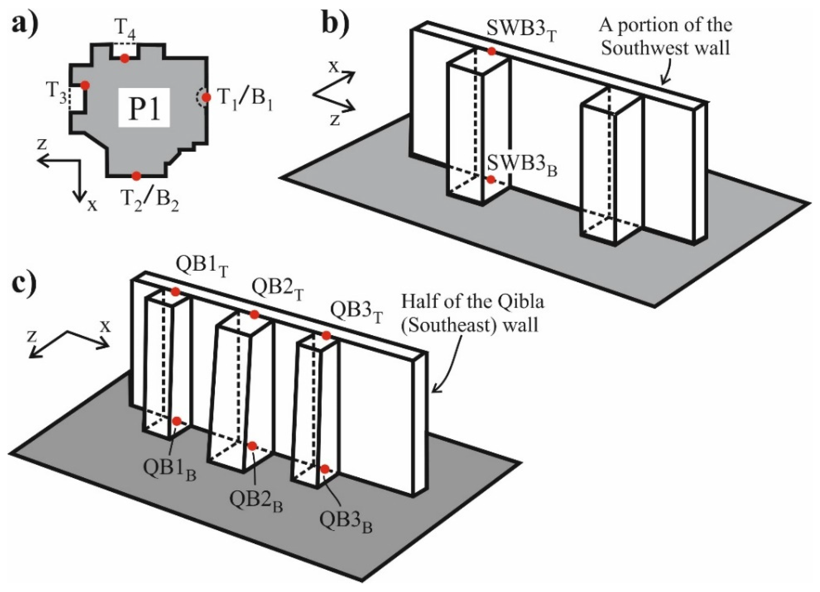
SWB3TThe buttress–wall outer interface midpoint of the SWB3 buttress at the level of the wall top section
SWB3BThe buttress–wall outer interface midpoint of the SWB3 buttress at the level of the wall bottom section
(QB1-2-3)TThe buttress–wall outer interface midpoints of the QB1, QB2, and QB3 buttresses at the level of the wall top section
(QB1-2-3)BThe buttress–wall outer interface midpoints of the QB1, QB2, and QB3 buttresses at the level of the wall bottom section
Table 8. Vertical stress values at some of the considered points of the mosque (in MPa).
PointPRE-STATEFIF-STATENO-STATE
B1 0.830.800.79
B2 0.940.930.92
T31.141.181.20
T41.181.201.23
SWB3B0.660.720.83
QB1B0.470.570.61
QB2B0.480.590.77
QB3B0.490.610.66
Table 9. Vertical/horizontal displacement values at some of the considered points of the mosque (in mm).
PointPRE-STATEFIF-STATENO-STATE
DT (Vertical displacement)6.06.086.10
(AR 1–2)T (Ver. displacemet)3.453.503.55
(AR 1–4)T (Ver. displacement)4.174.304.38
T1 (Hor. disp. in +z direction)0.290.380.44
T2 (Hor. disp. in −x direction)0.380.450.50
SWB3T (Hor. disp. in −x dir.)0.260.310.34
QB1T (Hor. disp. in +z dir.)0.090.140.16
QB2T (Hor. disp. in +z dir.)0.340.440.52
QB3T (Hor. disp. in +z dir.)0.280.450.62
Table 10. The variation in the horizontal earthquake resistance of the Süleymaniye depending on the buttress depths.
ModelMax. Base Shear Force, Rmax (kN)Wmodel
(kN)
Max. Seis. Coeff., c = Rmax/Wmodel
PRE-STATE (Qibla axis, +z direction)393,755564,7840.70
FIF-STATE (Qibla axis, +z direction)360,407542,8880.66
NO-STATE (Qibla axis, +z direction)349,283527,6560.66
PRE-STATE (Per-Qibla axis, −x direction)500,223564,7840.89
FIF-STATE (Per-Qibla axis, −x direction)439,331542,8880.81
NO-STATE (Per-Qibla axis, −x direction)410,936527,6560.78
Table 11. Structural performance levels according to SRMGHS-2017 [70] (Figure 22).
Performance LevelDefinition of Performance Level
Limited damage It corresponds to the damage level at which limited damage occurs (limited nonlinear behavior) to the structural elements of the structure.
Controlled damage This level corresponds to the level of controlled damage to the structural elements of the structure, which is mostly possible to repair.
Prevention of collapse This level corresponds to the situation in which severe damage occurs in the structural elements of the building, the structure is close to partial or complete collapse, but the collapse is prevented.
Table 12. Equivalent mass m* and conversion factor Γ values used in the N2 method.
m*(PRE-STATE)34,409 ton
Γ (PRE-STATE)4.64
m*(FIF-STATE)33,885 ton
Γ (FIF-STATE)4.61
m*(NO-STATE)33,370 ton
Γ (NO-STATE)4.58
Disclaimer/Publisher’s Note: The statements, opinions and data contained in all publications are solely those of the individual author(s) and contributor(s) and not of MDPI and/or the editor(s). MDPI and/or the editor(s) disclaim responsibility for any injury to people or property resulting from any ideas, methods, instructions or products referred to in the content.

