Article

Influence of Groundwater Level Rising on Mechanical Properties of Pile Foundations Under a Metro Depot in Loess Areas

1
Shaanxi Huashan Road and Bridge Group Co., Ltd., Xi’an 710016, China
2
School of Human Settlements and Civil Engineering, Xi’an Jiaotong University, Xi’an 710049, China
*
Author to whom correspondence should be addressed.
Buildings 2025, 15(8), 1341; https://doi.org/10.3390/buildings15081341
Submission received: 19 March 2025 / Revised: 14 April 2025 / Accepted: 17 April 2025 / Published: 17 April 2025
(This article belongs to the Special Issue Structural Analysis of Underground Space Construction)

Abstract

:
The span of pile foundations beneath metro depots typically ranges from 10 to 20 m, exhibiting a notably large span. This structural characteristic results in the pile foundations bearing a more concentrated upper load, while the interstitial soil between the piles bears minimal force. Concurrently, global climate change and enhanced urban greening initiatives have led to a significant increase in rainfall in northwest China, a region traditionally characterized by arid and semi-arid conditions. This climatic shift has precipitated a continuous rise in groundwater levels. Furthermore, the extensive distribution of collapsible loess in this region exacerbates the situation, as the rising groundwater levels induce loess collapse, thereby adversely affecting the mechanical behavior of the pile foundations. In light of these factors, this study utilized the pile foundations of a metro depot in Xi’an as a prototype to conduct static load model tests under conditions of rising groundwater levels. The experimental results reveal that the load–settlement curve of the pile foundations in the absence of groundwater exhibited a steep decline with distinct three-stage characteristics, and the ultimate bearing capacity was determined to be 5 kN. When the groundwater level is situated below the loess stratum, the settlement of both the pile foundations and the foundation soil, as well as the axial force, skin friction, and pile tip force, remains relatively stable. However, when the groundwater level rises to the loess stratum, there is a significant increase in the settlement of the pile foundations and foundation soil. Negative skin friction emerges along the pile shaft, and the bearing type of the pile foundation transitions gradually from a friction pile to an end-bearing pile. The influence range of the pile foundation on the settlement of the foundation soil is approximately three times the pile diameter.

1. Introduction

Loess, classified as an unconsolidated quaternary aeolian sediment [1], constitutes a globally significant geological formation that occupies approximately 10% of terrestrial surfaces, predominantly within mid-latitude arid and semi-arid climatic zones [2,3]. This distinctive material exhibits a predominant granulometric composition of silt-sized particles, accompanied by notable proportions of carbonate minerals and phyllosilicate constituents including kaolinite and montmorillonite [4,5]. The pedogenic processes inherent to loess formation result in a well-developed macroporous structure, wherein interparticle voids contain not only interstitial water but also structural cementation comprising particulate aggregations and colloidal matrices-critical elements maintaining metastable fabric integrity. The synergistic combination of high void ratios and hydrophilic mineralogy predisposes loess to hydro-consolidation phenomena, characterized by disintegration of cementitious bonds under aqueous conditions, subsequent pore structure collapse, and rapid shear strength reduction [6]. Current geotechnical evaluations estimate that approximately 60% of global loess deposits demonstrate collapsible behavior [7]. Within China’s northwestern territories, this problematic soil covers approximately 630,000 km2, with the majority exhibiting metastable characteristics [8,9,10]. Stratigraphic investigations by Zhu et al. [11] reveal substantial thickness variations (0–350 m) in the Loess Plateau sequences, averaging 92.2 m, with spatial distribution patterns strongly modulated by topographic constraints, vegetative cover dynamics, and anthropogenic disturbances. These findings collectively establish the northwestern Chinese loess deposits as extensive yet heterogeneously stratified formations. Anthropogenic climate change and urban greening initiatives have precipitated hydrologic regime alterations in historically drought-prone northwestern China. Hydrometeorological analyses by Li et al. [12] document a progressive intensification of mean annual precipitation in fluvial basins of northwest China, escalating from 160 mm (1960s) to 190 mm (2016), with continued positive trends. This precipitation amplification has induced regional aquifer recharge, evidenced by monitoring data from Xi’an demonstrating persistent groundwater elevation trends since 2002 [13,14,15]. Hydrogeologic interactions attain critical significance when rising water tables saturate collapsible loess strata, triggering fabric collapse under superincumbent loads. This phenomenon induces progressive foundation settlement, culminating in substantial bearing capacity degradation and consequential geotechnical failures in pile-supported structures [16].
The progressive implementation of China’s Western Development Strategy has catalyzed accelerated economic growth and urbanization in northwestern regions, accompanied by significant rural-to-urban migration [17]. This demographic shift has precipitated heightened pressure on urban transportation infrastructure. Urban rail transit systems, as sustainable mobility solutions, have gained prominence due to their operational efficiency, cost-effectiveness, and safety advantages, emerging as preferred transportation modalities in metropolitan areas [18]. Notably, while these systems demonstrate substantial societal benefits, their extensive spatial requirements and elevated capital investments necessitate innovative development approaches. The transit-oriented development (TOD) paradigm has consequently been adopted to optimize land utilization, enhance commercial potential, and ensure sustainable public transportation ecosystems [19]. This model integrates mixed-use complexes incorporating commercial, residential, and cultural facilities above metro depots, generating synergistic revenue streams to subsidize rail infrastructure development [20]. Functionally, metro depots serve as critical nodal facilities for rolling stock storage, maintenance, and operational management. Their specialized operational requirements necessitate substantial spatial footprints, with individual structures spanning 0.2–0.4 km2 [21,22]. The architectural configuration of these integrated depot-over-development complexes imposes unique geotechnical demands, particularly regarding foundation systems. The pile-supported substructures exhibit remarkable span dimensions (10–20 m), transmitting superstructure loads through beam–slab structural systems to pile caps, ultimately distributing concentrated forces of up to 10,000 kN per pile. Contrastingly, the interstitial soil zones designated for vehicle parking and maintenance operations sustain minimal surface pressures (<10 kPa), creating pronounced differential loading conditions between structural and non-structural areas. Current academic inquiry predominantly focuses on station construction mechanics and structural vibration responses in depot facilities [23,24,25,26,27,28]. Many scholars also pay less attention to the research on the static bearing properties of metro depot pile foundations, especially in collapsible loess areas. To address this knowledge gap, this study employs scaled model testing methodologies, utilizing Xi’an metro depot pile foundations as prototypical references, to systematically investigate load transfer mechanisms and bearing capacity evolution during groundwater elevation processes and obtain a reasonable foundation treatment range.

2. Test Materials and Instruments

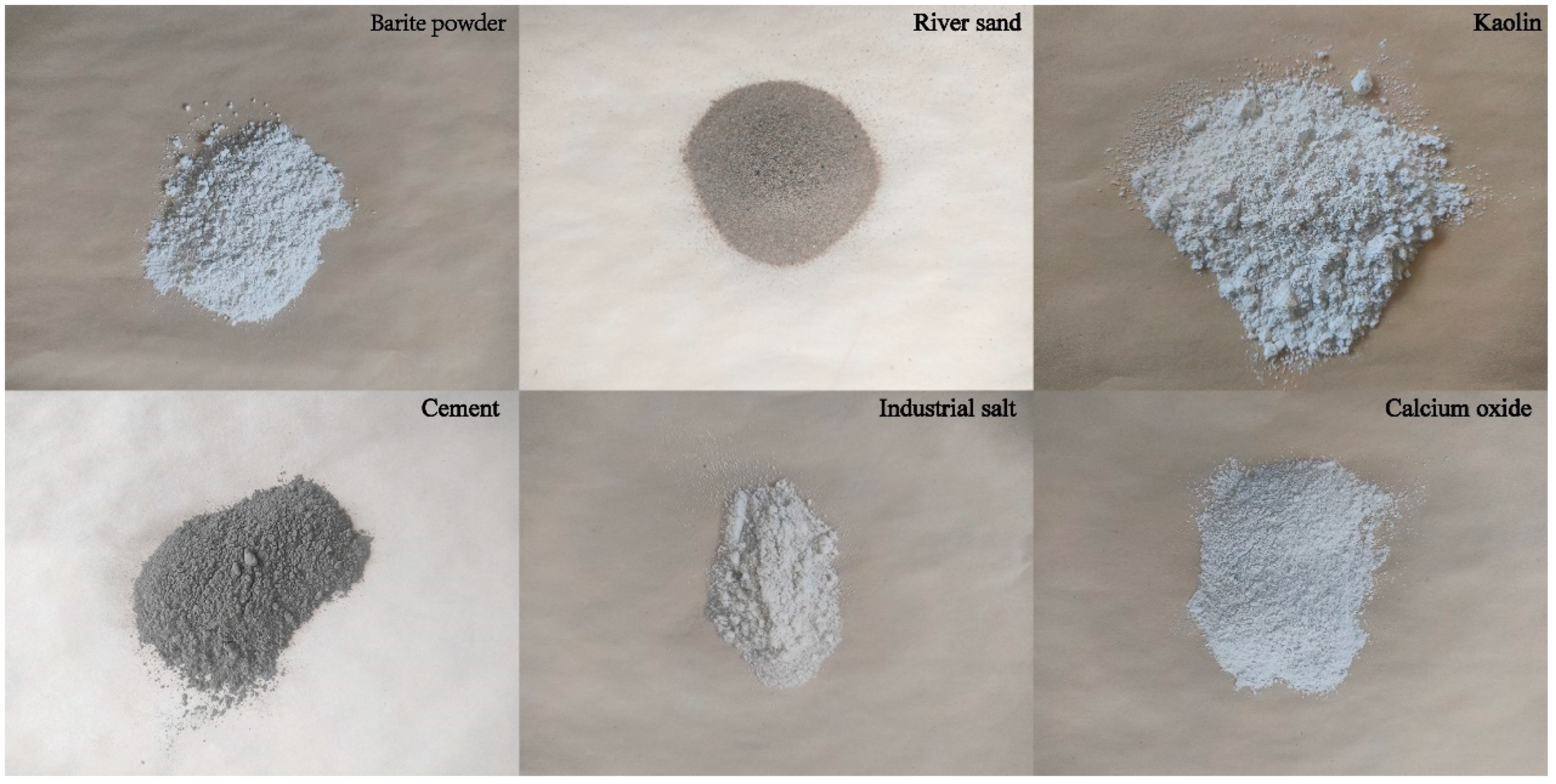
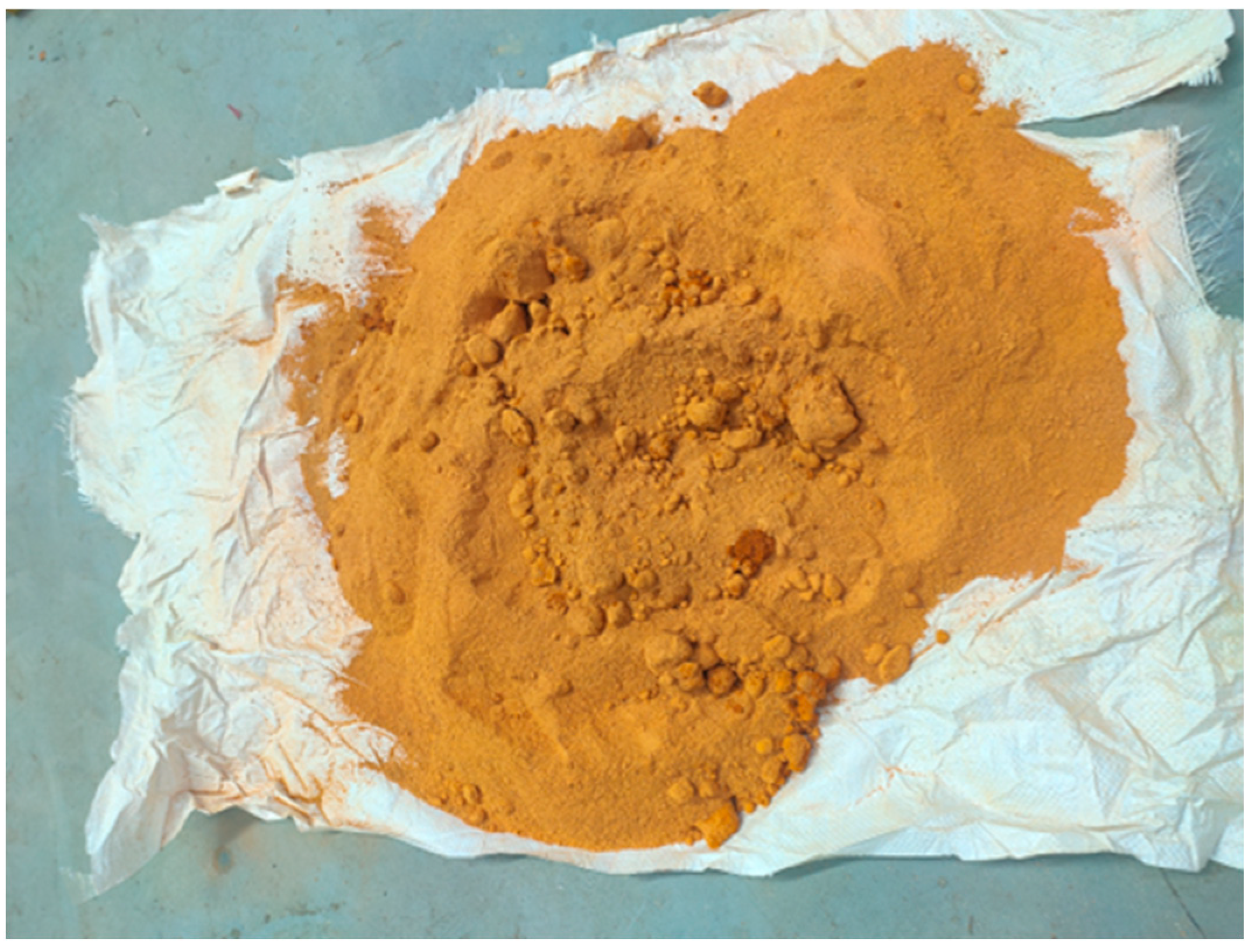
2.1. Artificial Collapsible Loess

The depositional processes of loess engender distinct anisotropic structural characteristics, manifested through preferential vertical alignment of soil particles forming dense bedding planes, contrasted with relatively disorganized horizontal particle arrangements. This anisotropy induces marked variations in physico-mechanical properties along different axes, resulting in significant spatial heterogeneity of engineering parameters across depositional environments and stratigraphic depths in natural loess formations [29]. Additionally, the structure of natural loess can be destroyed during the preparations of remolded soil. To address these problems, the experimental investigation employed engineered collapsible loess specimens formulated through controlled material synthesis. The synthetic loess matrix, designed to replicate the granulometric and mineralogical characteristics of natural deposits, comprises precisely proportioned constituents: barite powder (25%), fluvial sand (35%), kaolin (30%), Portland cement (3%), sodium chloride (5%), and calcium oxide (2%) [30] (Figure 1). This formulation strategically utilizes:
  • Barite powder and fluvial sand as granular constituents regulating bulk density through particle packing density modulation;
  • Fluvial sand as shear strength modifiers controlling internal friction characteristics and deformation response;
  • Hydraulic cement as supplementary cementitious agents;
  • Kaolin forms clay cementations;
  • Calcium oxide undergoing carbonation reactions with atmospheric CO2 in aqueous conditions to generate calcium carbonate cementation.
This multi-phase cementation system effectively simulates the metastable fabric of natural collapsible loess while ensuring experimental repeatability and parameter controllability—critical requirements for rigorous model testing protocols.
The interparticle contact architecture of natural loess, characterized by point-to-point particle connections, engenders an intrinsically unstable metastable fabric that fundamentally governs its collapsibility mechanisms [31,32]. This inherent characteristic necessitates rigorous replication of natural intergranular contact patterns during synthetic specimen fabrication. Building upon the methodological advancements of Assalay et al. [33,34] and Jefferson and Ahmad [35], whose Monte Carlo simulations substantiated the efficacy of the free-drop method in stimulating the deposition process of natural loess. Hence, the soil particles of the artificial loess sample prepared by the free-drop method can also form point-point contact. The specimen preparation sequence is delineated as follows (Figure 2):
(1)
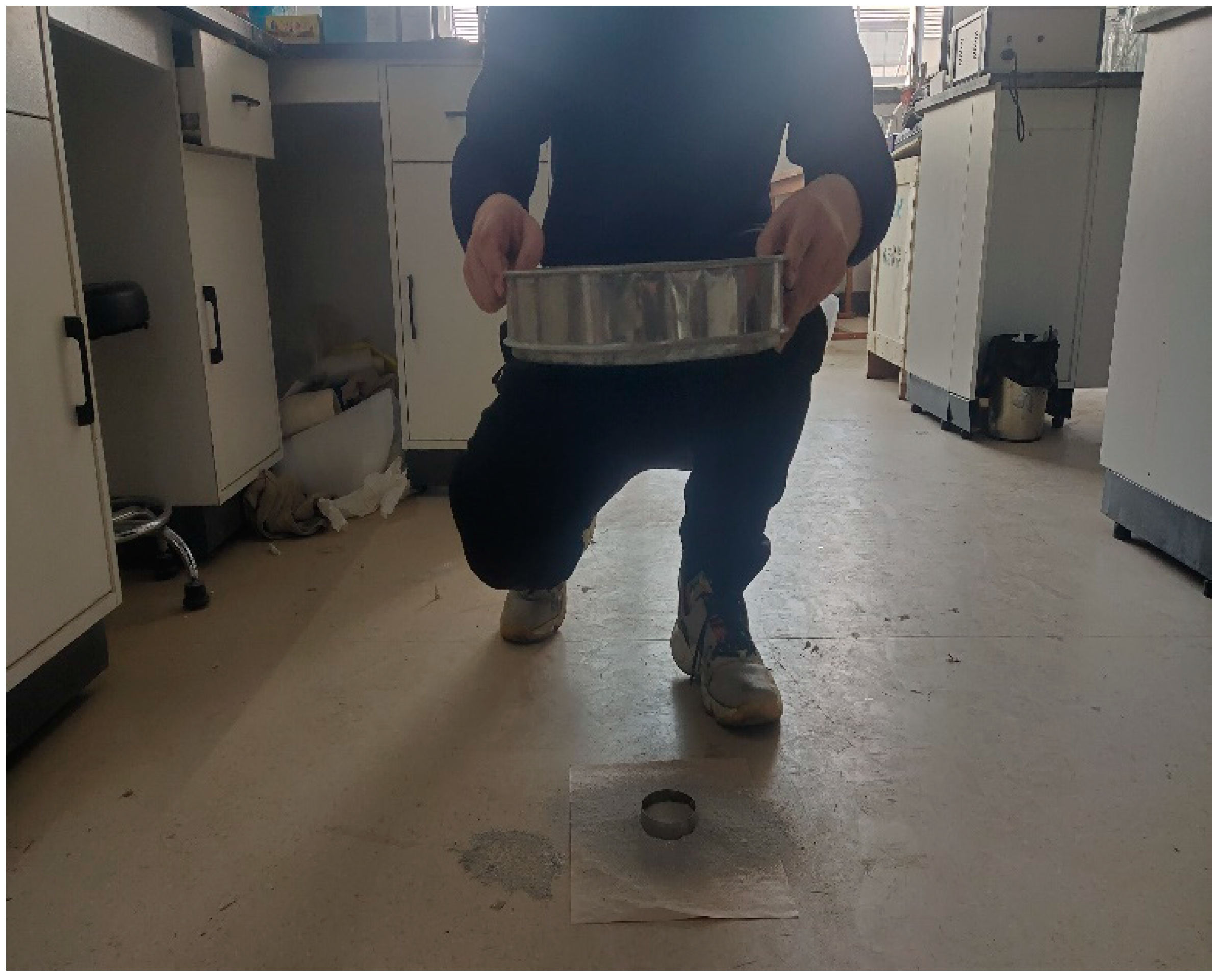
Precisely proportioned constituent materials were homogenously blended through mechanical mixing. A granulometric sieve (2 mm aperture) was positioned vertically at 20–40 cm above a standardized sampling ring. The composite mixture was systematically introduced onto the sieve platform, followed by continuous vibration. This methodology can simulate natural depositional processes.
(2)
The prepared specimen surface was smoothed, followed by static compaction to achieve predetermined density specifications. Subsequently, specimens were subjected to isothermal desiccation in an oven maintained at 50 ± 1 °C for 24 h. Finally, a sprayer was used to sprinkle the sample with water mist and make it reach the optimum moisture content.
The bearing stratum was using non-collapsible loess sourced from Xianyang, Shaanxi Province (Figure 3). The physical and mechanical properties of artificial loess and non-collapsible loess are shown in Table 1 and Table 2. Table 3 shows the collapsible coefficient of artificial loess. The specific gravity was determined using the hydrometer method, while the optimum moisture content was ascertained through moisture-density tests. The plastic and liquid limits were established via Atterberg limits tests. Cohesion and the angle of internal friction were derived from the direct shear tests. Void ratio and modulus of compression were acquired through standard compression tests. Finally, collapsibility coefficients were measured from wetting-induced compression tests.

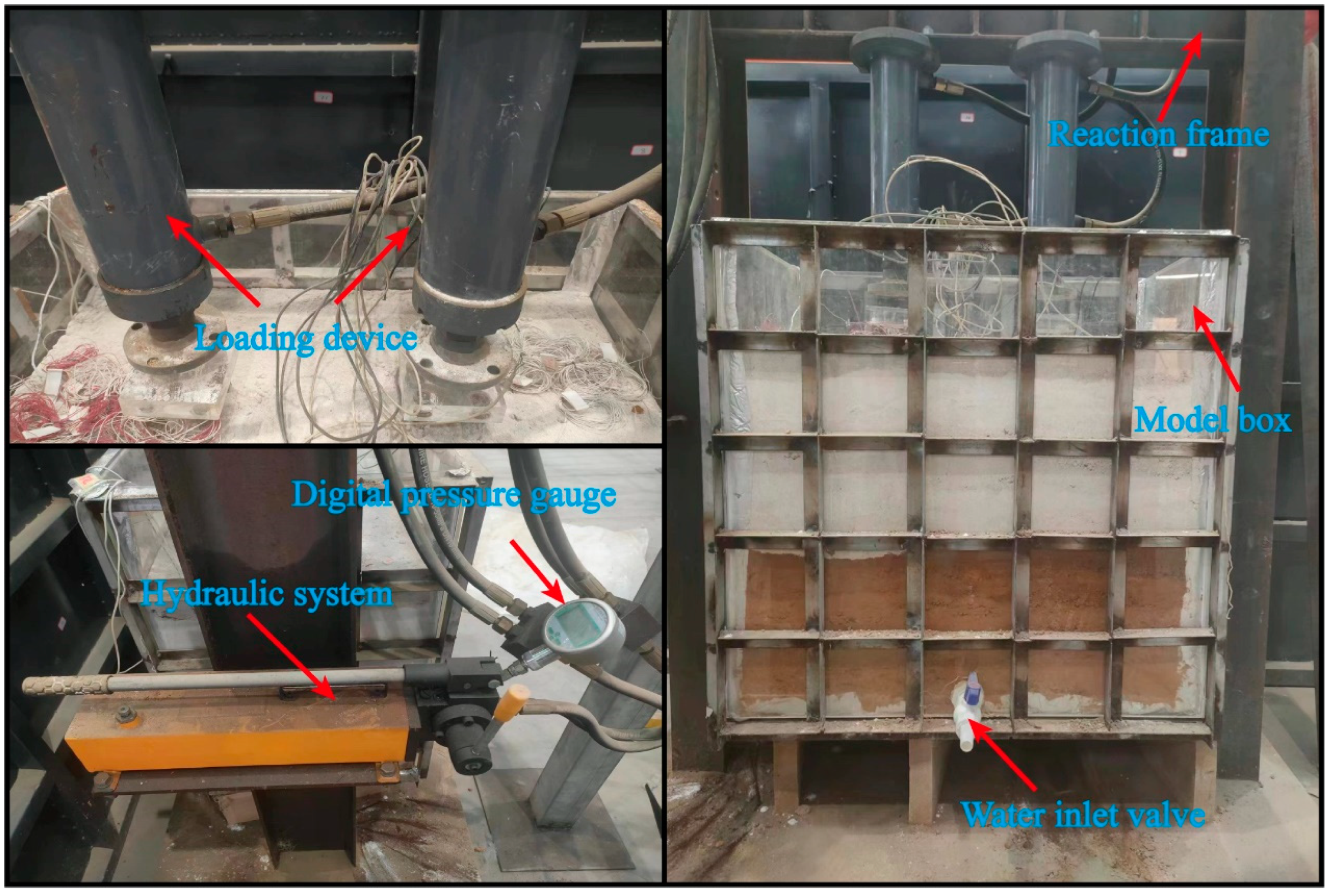
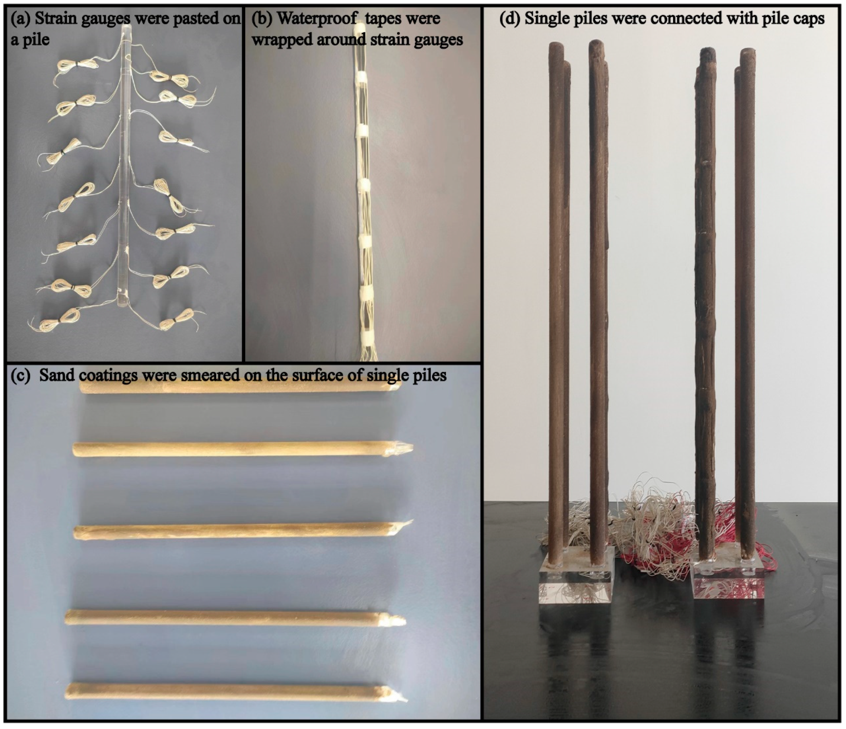
2.2. Model Box and Model Piles

The experimental configuration employed a plexiglass test chamber (80 cm × 50 cm × 80 cm internal dimensions) for deformation monitoring, as illustrated in Figure 4. The parameters of the plexiglass are shown in Table 4. Structural integrity was ensured through peripheral reinforcement using hot-rolled I-beam steel sections, while a water inlet valve integrated at the lower part facilitated controlled groundwater elevation. The test chamber was rigidly mounted on a reinforced reaction frame equipped with two servo-controlled hydraulic jacks suspended from the upper crossbeam. The hydraulic system on the left side of the reaction frame can provide pressure for the actuators, and a digital pressure gauge was installed above the hydraulic system to check the loading pressure in real time.
In the model test, 2 × 2 pile groups with a similarity ratio of 1:50 were used. The single piles and pile caps were made of plexiglass. The pile diameter was 2 cm and the pile length was 50 cm. The pile spacing was 6 cm. The size of a pile cap size was 10 cm × 10 cm × 3 cm. The preparation processes were as follows (Figure 5):

2.3. Test Condition Setting

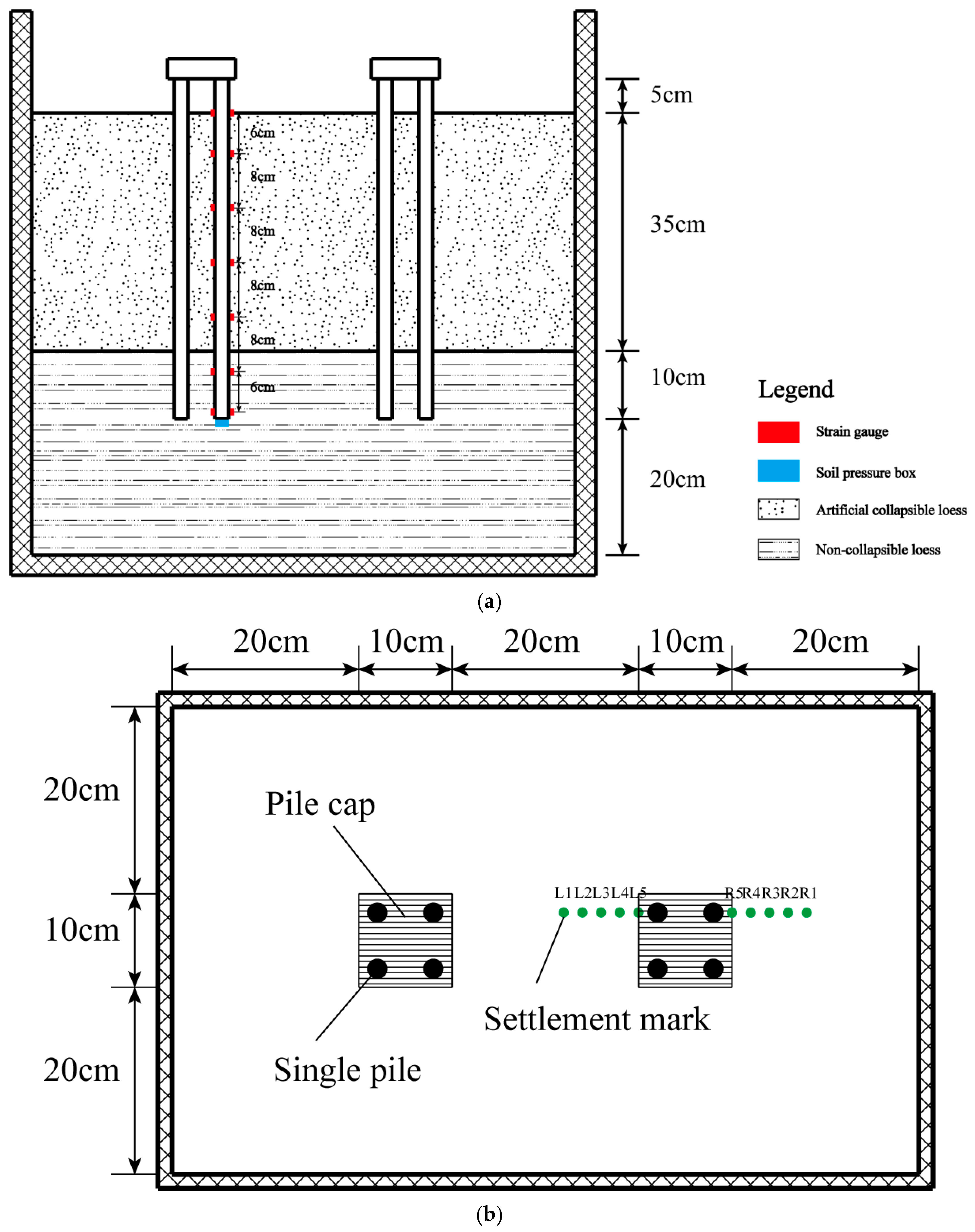
2.3.1. The Layout of Pile Foundations

The geometric configuration of the pile foundation, as illustrated in Figure 6, comprises a vertically embedded depth of 45 cm, with stratigraphic composition specifically divided into a 35 cm thick engineered collapsible loess stratum overlying a 30 cm compacted bearing stratum. Pile elements were positioned with a center-to-center spacing of 20 cm. Surface deformation monitoring was implemented through an array of ten settlement marks per lateral boundary. Instrumentation protocols included (Figure 7):
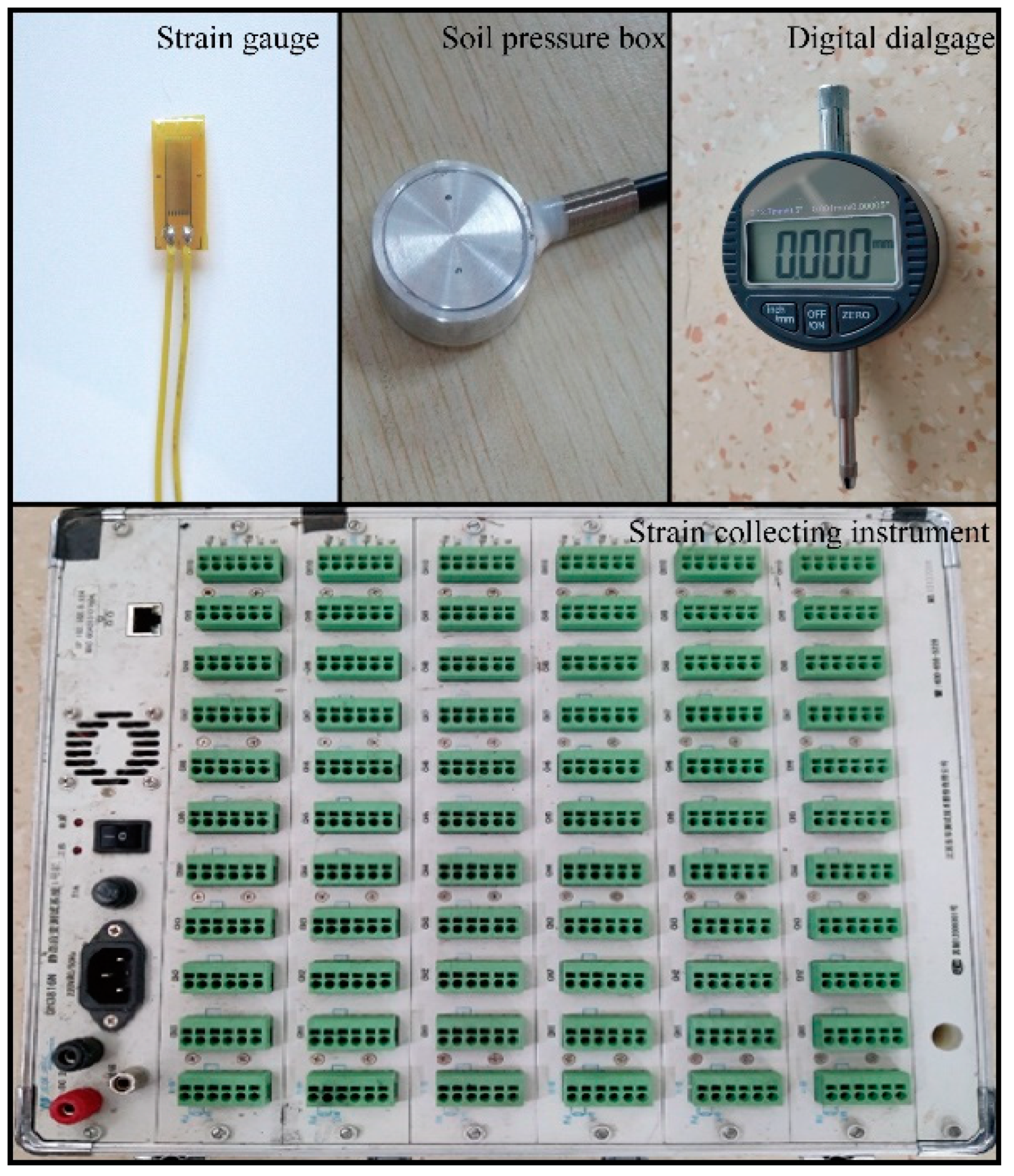
  • Strain Analysis: Symmetrically distributed strain gauges (120 Ω foil-type, ±1 με accuracy) along pile shafts to capture strain change;
  • Tip Resistance Monitoring: Miniaturized soil pressure transducers installed at pile tip.

2.3.2. The Loading Process of the Without Groundwater Condition

The first testing condition is loading without groundwater. Before loading, the ultimate bearing capacity of a single pile was estimated according to the Technical Code for Building Pile Foundations (JGJ 94-2008) [36], as shown in Equation (1):
Q u k = Q s k + Q p k = u q s i k l i + q p k A p ,
where Q u k is the ultimate bearing capacity of a single pile; Q s k and Q p k are the standard values of total ultimate skin friction and total ultimate pile tip force, respectively; u is the circumference of the pile body; q s i k is the standard value of the ultimate skin friction of soil layer i around the pile; l i is the thickness of soil layer i around the pile; q p k is the standard value of ultimate pile tip force; A p is cross-sectional area of the single pile. According to the recommended value in the specification, q s 1 k = 25   kPa , q s 2 k = 55   kPa , and q p k = 1500   kPa were taken. The calculated determination yielded an ultimate bearing capacity of 1.36 kN for individual model piles. Theoretical group capacity, calculated through arithmetic superposition without considering pile interaction effects, was estimated at 5.44 kN. To accommodate experimental practicality, the design bearing capacity was conservatively established at 5.5 kN. Loading protocols strictly adhered to the Technical Code for Testing of Building Foundation Piles (JGJ 106-2014) [37], implementing the following controlled sequence:
  • Load incrementation:
    • Primary stage: 2× graded load (1.0 kN);
    • Subsequent stages: 0.5 kN increments (1/11 of ultimate bearing capacity);
  • Stable criteria: ≤0.1 mm displacement over a consecutive 2 h monitoring period post 30 min load maintenance;
  • Termination conditions: settlement exceeds twice the preceding stage’s displacement.

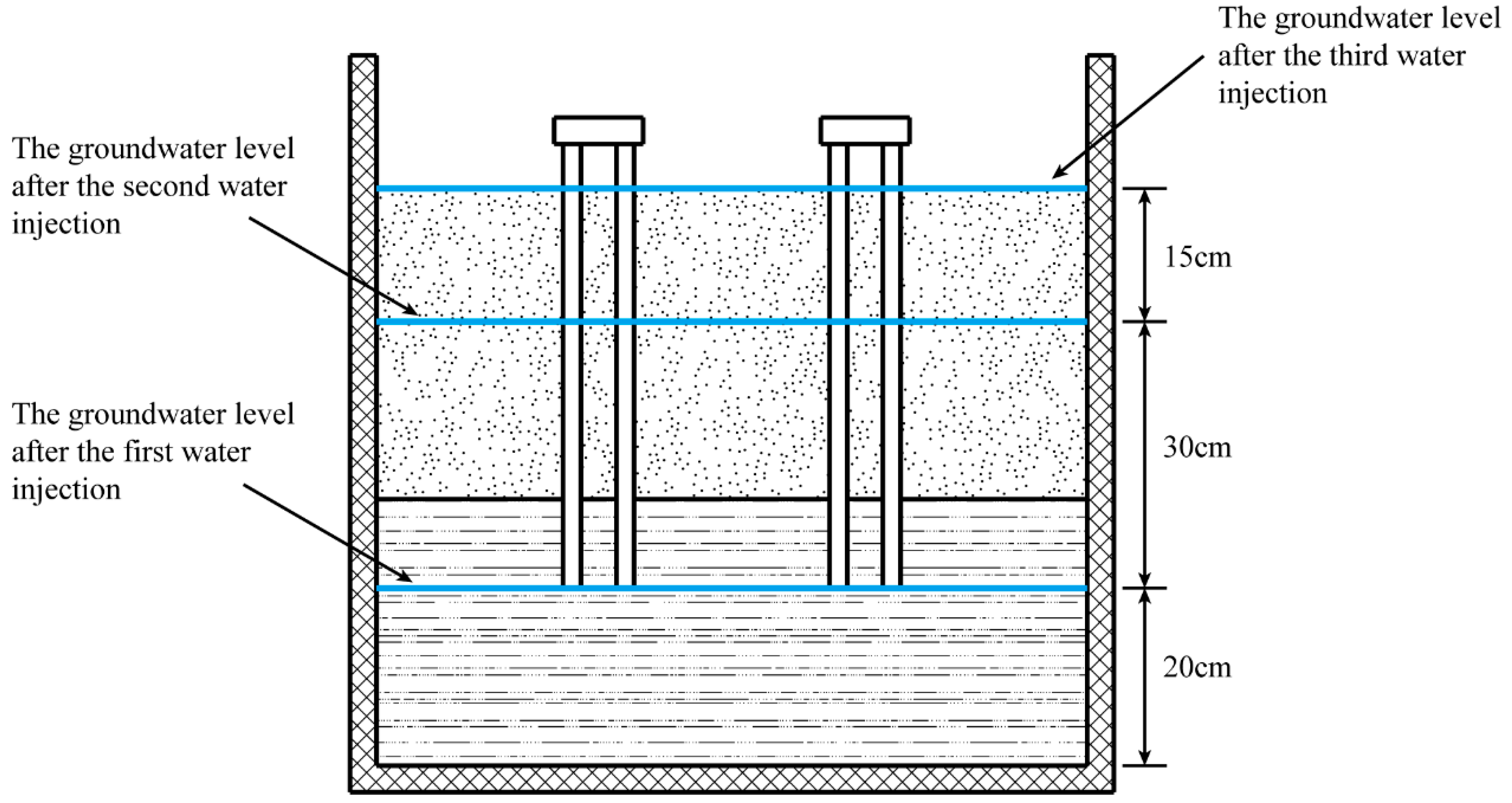
2.3.3. Setting of Groundwater Level and Upper Load

The other testing condition is loading while the groundwater rises slowly. Figure 8 delineates the phased elevation of the phreatic surface during hydraulic boundary condition simulations. The groundwater regime was systematically modulated through three controlled injection phases:
  • Initial phase: stabilization of the water table within the bearing stratum post-injection.
  • Second phase: groundwater rises to permeate the part of artificial collapsible loess stratum.
  • Tertiary phase: full saturation of the soil matrix through complete inundation.
The tests incorporated two distinct loading configurations under groundwater elevation scenarios: the upper load of 1/4 and 1/2 of the ultimate bearing capacity, respectively. Data acquisition at 8 h intervals across three sequential measurement cycles (over a cumulative 24 h observation period).

3. Static Load Test Under the Condition of No Groundwater

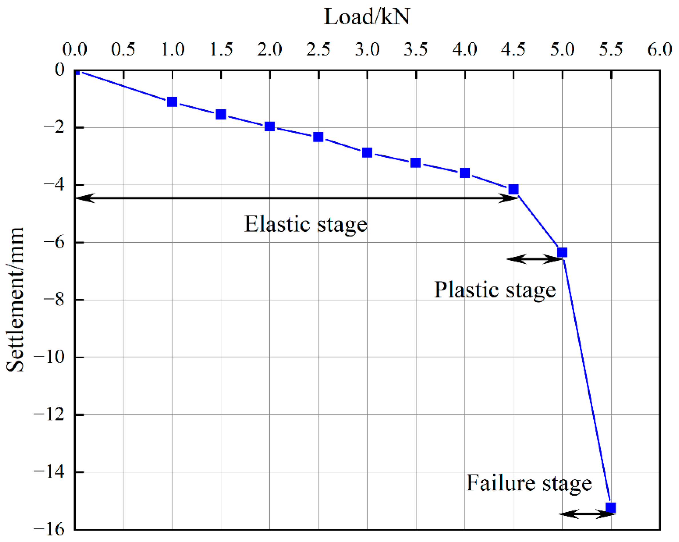
3.1. Change of Pile Foundations Settlement with the Applied Load

The settlement of the pile foundation is an important index to judge the bearing capacity of the pile foundation. Figure 9 delineates the load–settlement behavior of the pile foundation system, exhibiting three distinct deformation regimes demarcated by inflection points in the curve:
  • Linear elastic phase (0–4.5 kN): axial displacement demonstrated proportionality to applied load, indicative of reversible elastic strain.
  • Plastic yielding phase (4.5–5 kN): a nonlinear transition occurred, signaling the appearance of unrecoverable deformation.
  • Structural failure phase (>5 kN): displacement escalates to 15.44 mm at 5.5 kN load, exceeding the 6.55 mm displacement at 5 kN by a factor of 2.36.
The characteristic of change of settlement is in keeping with the conclusions of Chai et al. [6]. Per the Technical Code for Building Pile Foundations (JGJ 94-2008) [36], the ultimate bearing capacity Q u l t is defined at the load preceding a doubling of displacement under incremental loading ( s n + 1 / s n > 2 ). Experimental validation confirmed Q u l t = 5   kN , with subsequent load increments inducing metastable collapse. Applying a conventional safety factor K s = 2 , the allowable bearing capacity is derived as Q a l l o w = Q u l t / K s = 2.5   kN .

3.2. Distribution of Axial Force and Skin Friction in Pile Shafts

The interaction between the pile foundation and the soil can be revealed to a certain degree by studying the axial force and skin friction. Figure 10 and Figure 11 delineate the axial force distribution and skin friction characteristics of the pile foundation system under non-saturated conditions. Upon application of vertical loading, the pile undergoes compressive deformation, initiating vertical displacement. The load transfer mechanism can be explained as: superstructure loads are transmitted via the pile cap to the pile shaft and subsequently redistributed to the surrounding soil matrix through interfacial shear stresses. Differential settlement arises between the pile and adjacent soil mass due to disparities in stiffness moduli, generating relative displacement at the soil–pile interface. When pile settlement exceeds peripheral soil displacement ( s p > s s ), positive skin friction develops, opposing the load direction and contributing to bearing capacity mobilization. As evidenced by the axial force profiles, a progressive attenuation of axial forces occurs with depth. The distribution form of axial force and skin friction in the test is similar to the results obtained by Zhang et al. [16].

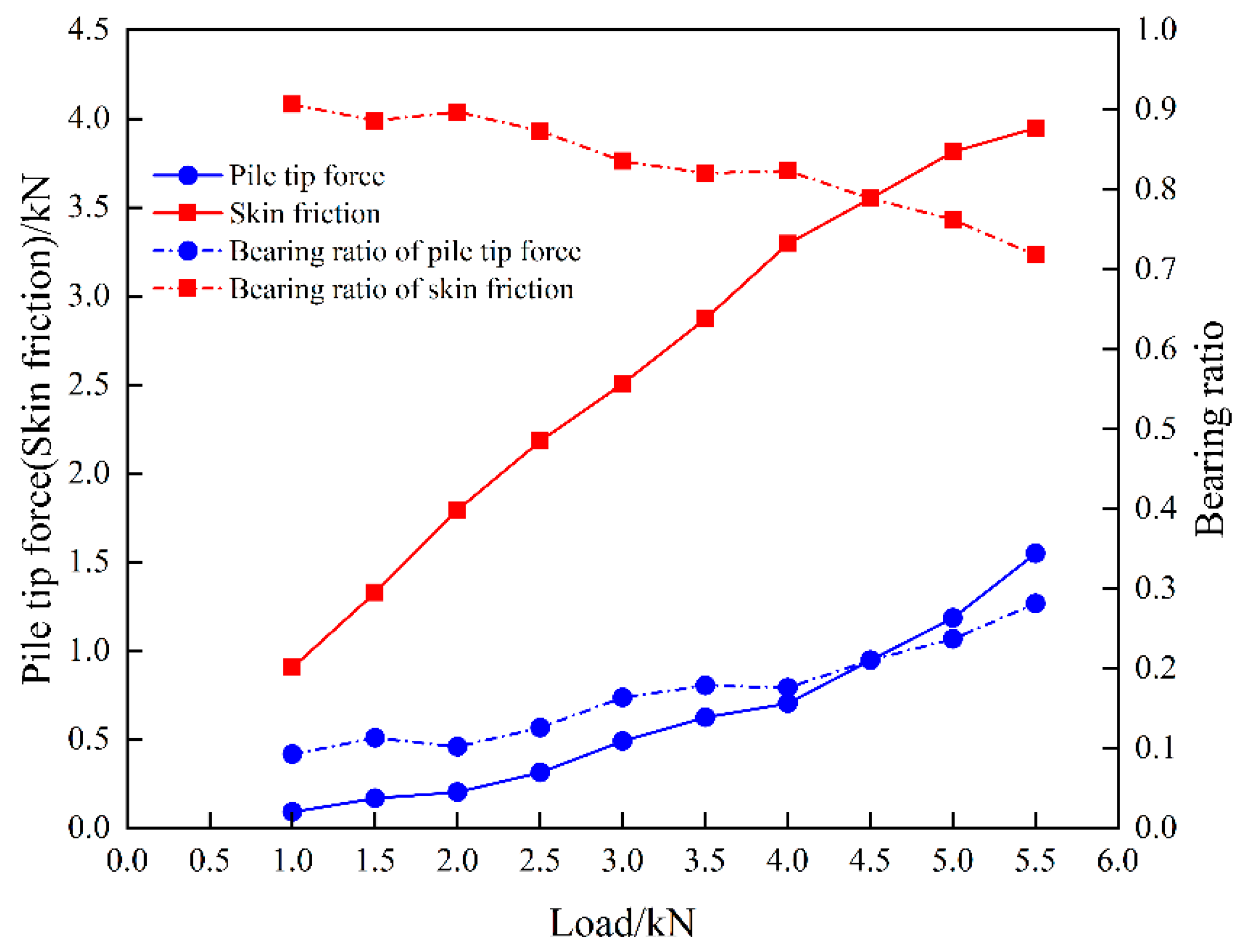
3.3. Change of Pile Tip Force with the Applied Load

The bearing type of the pile foundation can be judged by monitoring the pile tip force. Figure 12 delineates the evolution of pile tip force under progressive axial loading. A direct proportionality is observed between the superstructure load application and the concurrent escalation of both tip force and skin friction. The load transfer efficacy is quantified through the bearing ratio r s , mathematically expressed as Equation (2) [38]:
r s = Q P ,
where Q is the pile tip force (skin friction) and P is the applied load. Figure 12 delineates the temporal evolution of load-bearing ratios for pile tip force and skin friction under progressive axial load. While both pile tip force and skin friction exhibit monotonic increases with applied load, proportional contributions demonstrate an inverse proportionality. This divergence becomes markedly pronounced beyond the ultimate bearing capacity threshold, which manifests in the pile foundation accelerating to the end-bearing pile (load mainly borne by pile tip force) transformation from the friction pile (load mainly borne by skin friction).

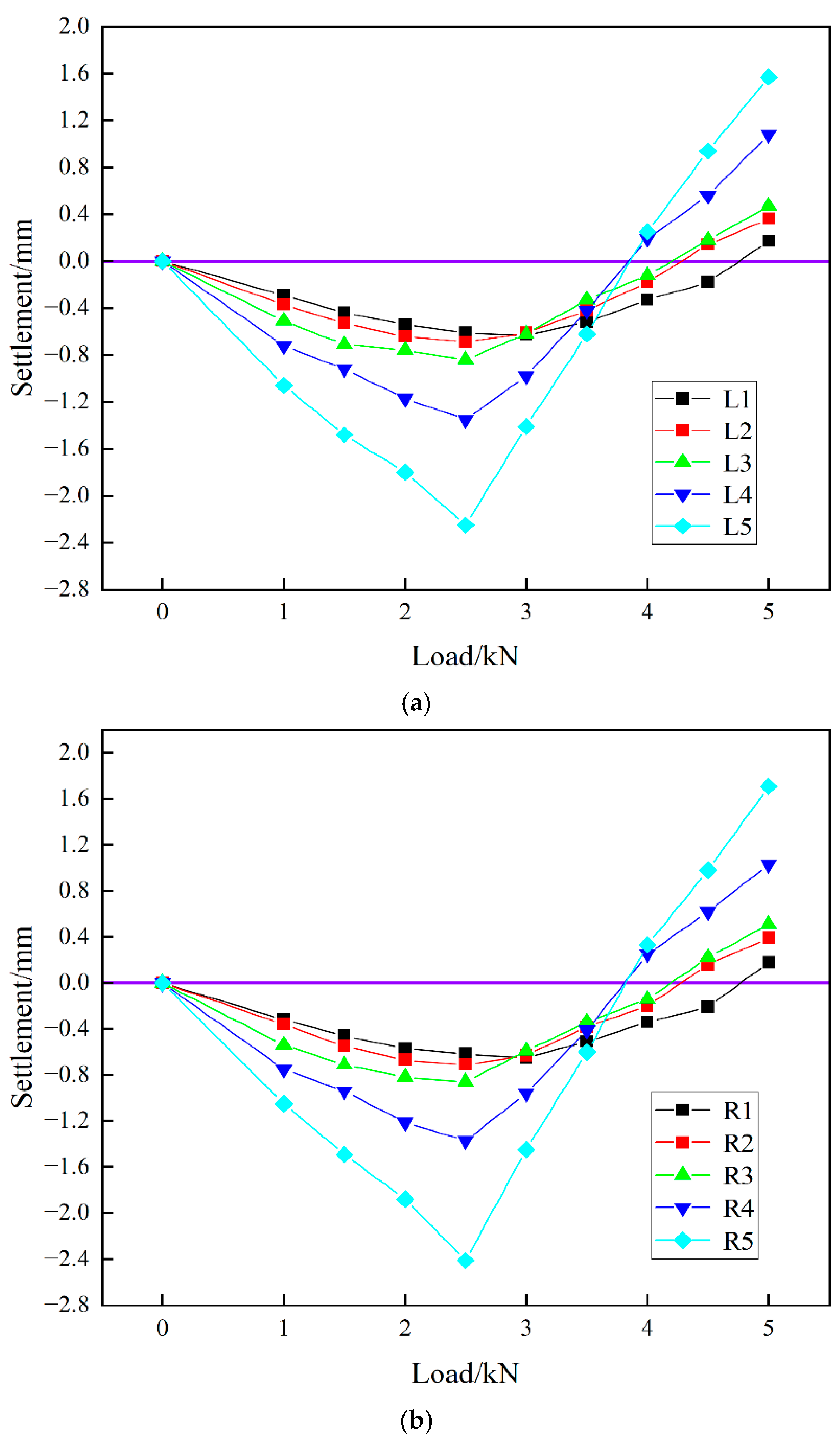
3.4. Change of Foundation Soil Settlement with the Applied Load

The variation of foundation soil settlement can reveal the influence of collapsibility on foundation settlement. Figure 13 delineates the differential settlement behavior of laterally symmetric measurement nodes (L1~L5 and R1~R5) adjacent to the pile foundation. The displacement magnitudes exhibit statistically congruent evolutionary patterns across mirrored positions. The subsidence metrics follow a trajectory characterized by:
  • Initial compression phase (0–1.5 kN): progressive settlement accumulation (∆s = 0.44–1.49 mm) under linearly increasing loads;
  • Yield phase (1.5–2.5 kN): plastic deformation is generated gradually and maximum subsidence is attained finally;
  • Post-yield heave phase (2.5 kN): when the load exceeds the elastic limit of the soil, a plastic zone is formed under the pile tip. At this time, the pile tip compresses the soil, resulting in the increase of radial stress. After extension of the plastic zone, the lateral earth pressure is released, resulting in the hump of the soil.
Notably, the critical load corresponds precisely to the allowable bearing capacity derived in Section 3.1 via limit state analysis.
The influence coefficient k is defined as shown in Equation (3) [38]:
k = s r
where s is the vertical settlement of the foundation soil and r is the absolute value of the radial distance from the pile axis. k < 0 indicates that settlement of the foundation soil has been generated and k > 0 indicates that the foundation soil has been uplifted. The greater the absolute value of k , the more obvious the effect of pile foundation settlement driving foundation soil settlement.
Figure 14 delineates the spatial distribution of the influence coefficient quantifying the interaction intensity between the model pile and adjacent foundation soils under unsaturated conditions. The bilateral measurement nodes (L1–L5 and R1–R5) exhibit statistically congruent influence coefficient profiles. It can be seen from the figures that the absolute value of the influence coefficient decreases rapidly, and the influence coefficient has no obvious change when it exceeds the 3D range. The test findings substantiate that under the condition of no groundwater, pile–soil interaction mechanics are governed by a confined influence zone extending radially to 3D, beyond which stress coupling diminishes asymptotically.

4. Static Load Test with the Condition of Rising Groundwater

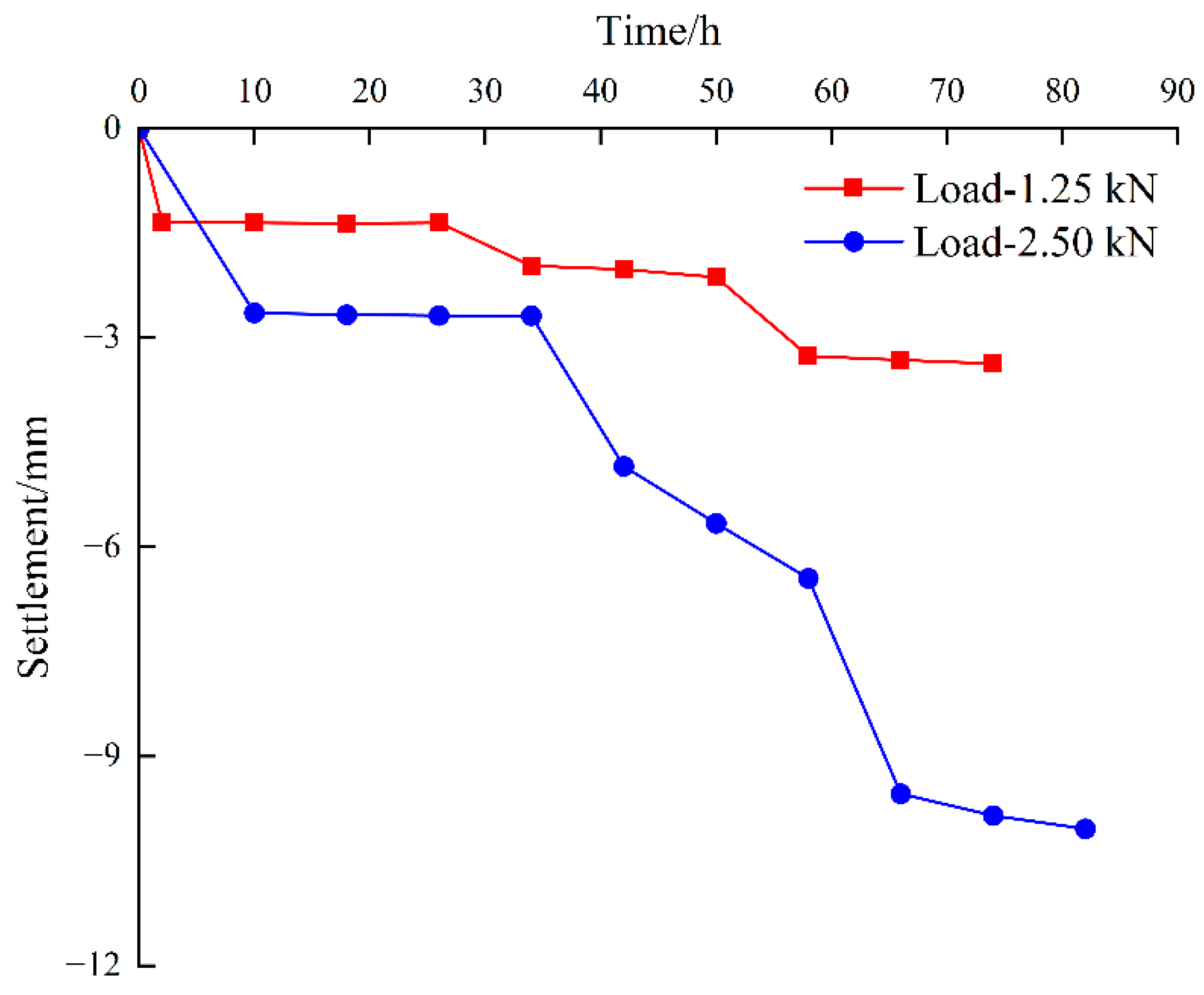
4.1. Change of Pile Foundations Settlemnt with the Immersion Time

Figure 15 illustrates the variations in pile foundation settlement over time when subjected to upper loads of 1.25 kN and 2.5 kN. The data indicate that while the magnitude of settlement differs under these two loads, the overall trend in settlement follows a similar pattern. Initially, for the first 24 h following loading, the pile foundation settlement remains relatively stable due to the water level being maintained within the bearing strata, hence not impacting the collapsible loess layer. Subsequent to the second water injection, significant settlement occurs as a result of the partial collapse of the saturated artificial loess. This trend continues, albeit at a reduced rate, following the cessation of water injection, as capillary action leads to the collapse of some artificial loess above the water level. After the third injection, there is a complete collapse of the artificial loess, leading to a substantial increase in pile foundation settlement. The settlement then tends to stabilize within 24 h after stopping the water injection. Ultimately, the pile foundation settles approximately three to five times more than it would in the absence of groundwater.

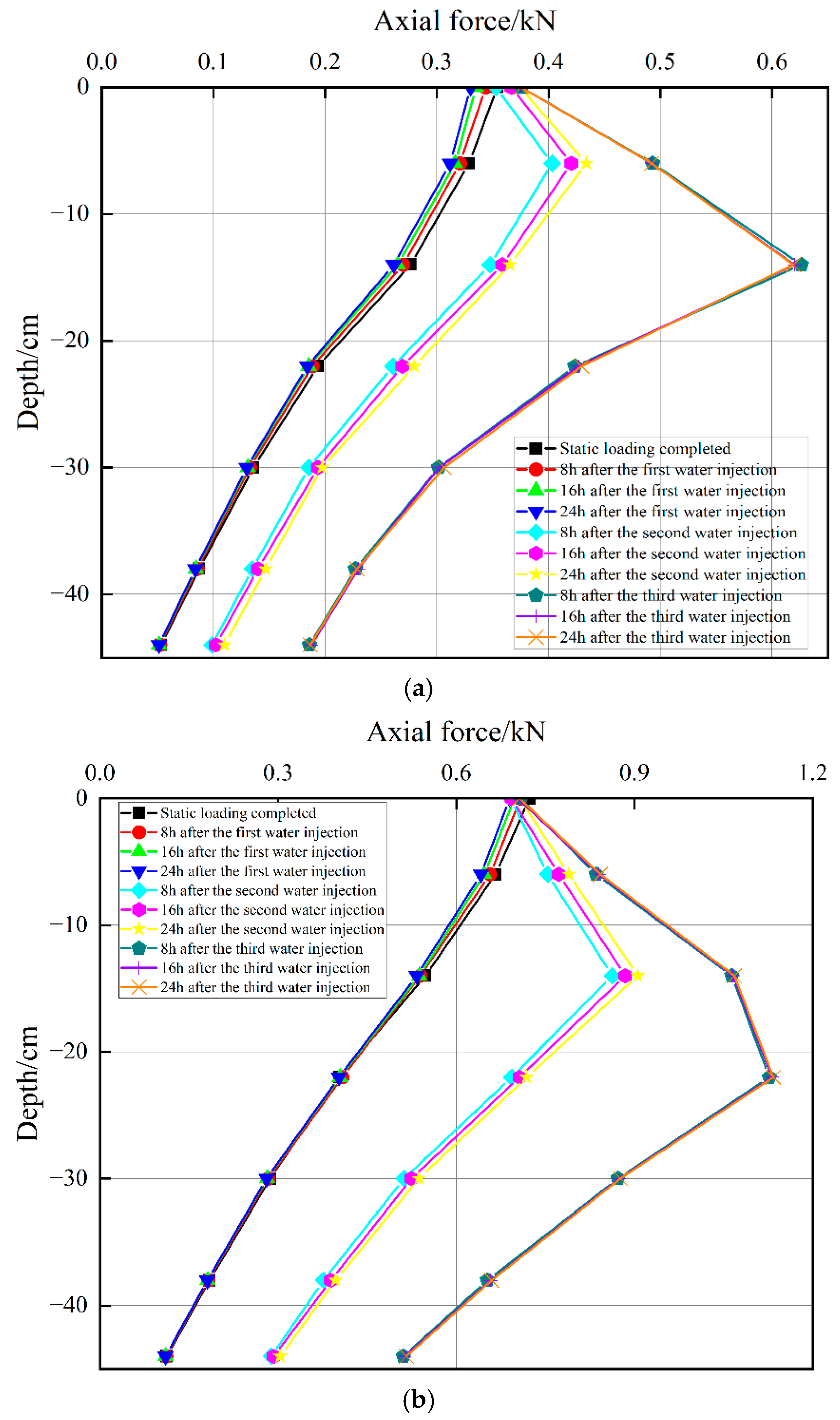
4.2. Distribution of Axial Force and Skin Friction in Pile Shafts

Figure 16 depicts the axial force in the pile under applied upper loads of 1.25 kN and 2.5 kN. Under these two different vertical loads, the axial force in the pile exhibits a consistent trend. Within the first 24 h following the completion of pile foundation loading, the axial force slightly decreases due to groundwater buoyancy, although this reduction is minimal and negligible. Within 8 h subsequent to the second water injection, there is an increase in the axial force at the top of the pile, which continues to rise in the period from 8 to 24 h after injection. Following the third water injection and the complete collapse of the artificial loess, the axial force further increases, and then it eventually stabilizes.
Figure 17 shows the pile skin friction under upper loads of 1.25 kN and 2.5 kN. Following loading, the pile skin friction registers as positive, aligning with the results observed in the preceding section. Within 24 h post first water injection, the presence of groundwater slightly reduces the skin friction, yet this reduction remains negligible. After the second water injection, with the partial collapse of the artificial loess layer, soil settlement intensifies and eventually exceeds that of the pile foundation. Consequently, the soil exerts a downward pull on the pile shaft, resulting in negative friction. This phenomenon also explains the continuous increase in the axial force of the pile foundations along the depth range. Once the water injection ceases, capillary action causes water to rise to the upper levels of the artificial loess layer, subsequently increasing negative skin friction resistance; however, its distribution depth on the pile does not extend. Following the third injection and the complete collapse of all artificial loess, negative friction resistance escalates, and the distribution range of negative skin friction expands, indicating that the neutral point’s location descends in conjunction with the rising groundwater level. The change of skin friction and neutral point coincides with the test consequences of Zhang [38].

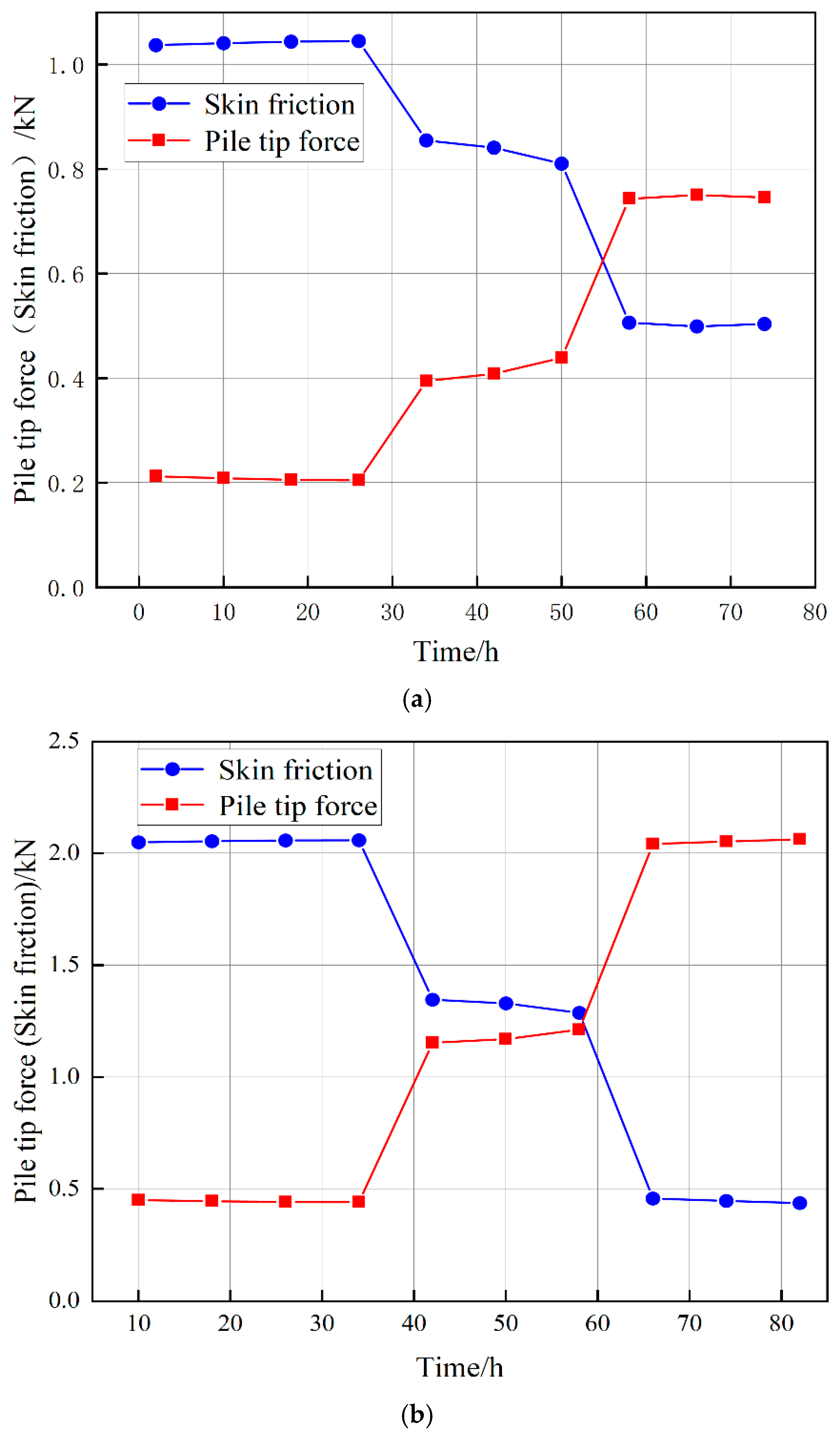
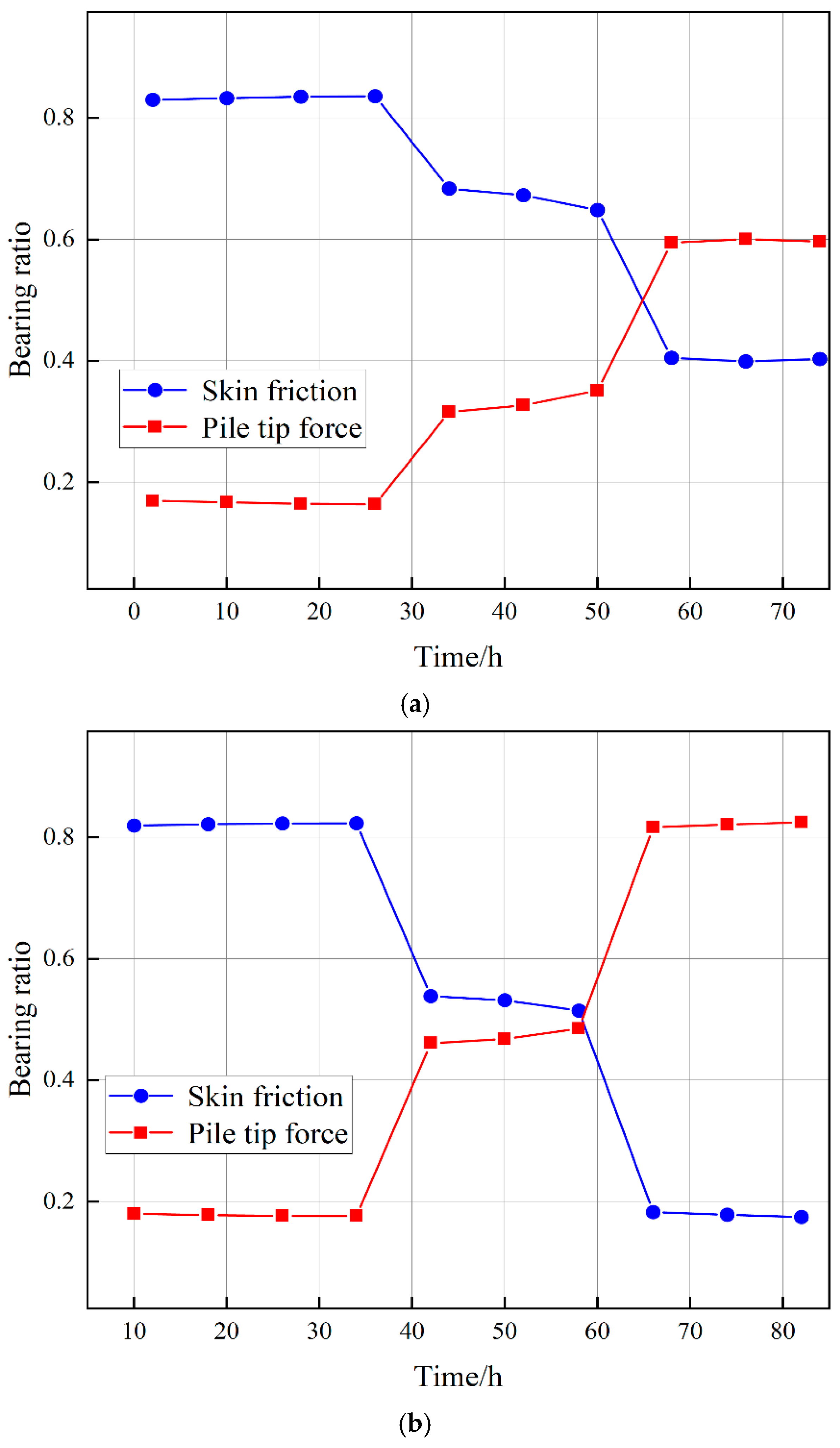
4.3. Change of Pile Tip Force with the Immersion Time

Figure 18 displays the variation in pile tip force under loads of 1.25 kN and 2.5 kN. The pile tip force and skin friction remain constant from the conclusion of loading until 24 h after the initial water injection. Following the second water injection, the collapse of the artificial loess leads to reduced pile–soil relative displacement. Given that skin friction is positively correlated with the relative displacement of pile–soil, as indicated by reference [39], the skin friction diminishes substantially, while the pile tip force correspondingly increases markedly. After the third water injection, the complete collapse of the artificial loess causes a further decrease in skin friction.
Figure 19 presents the bearing ratio curve of pile tip force under both load conditions as calculated by Equation (2). This figure illustrates that the pile foundation progressively transitions from a friction pile to an end-bearing pile with successive water injections.

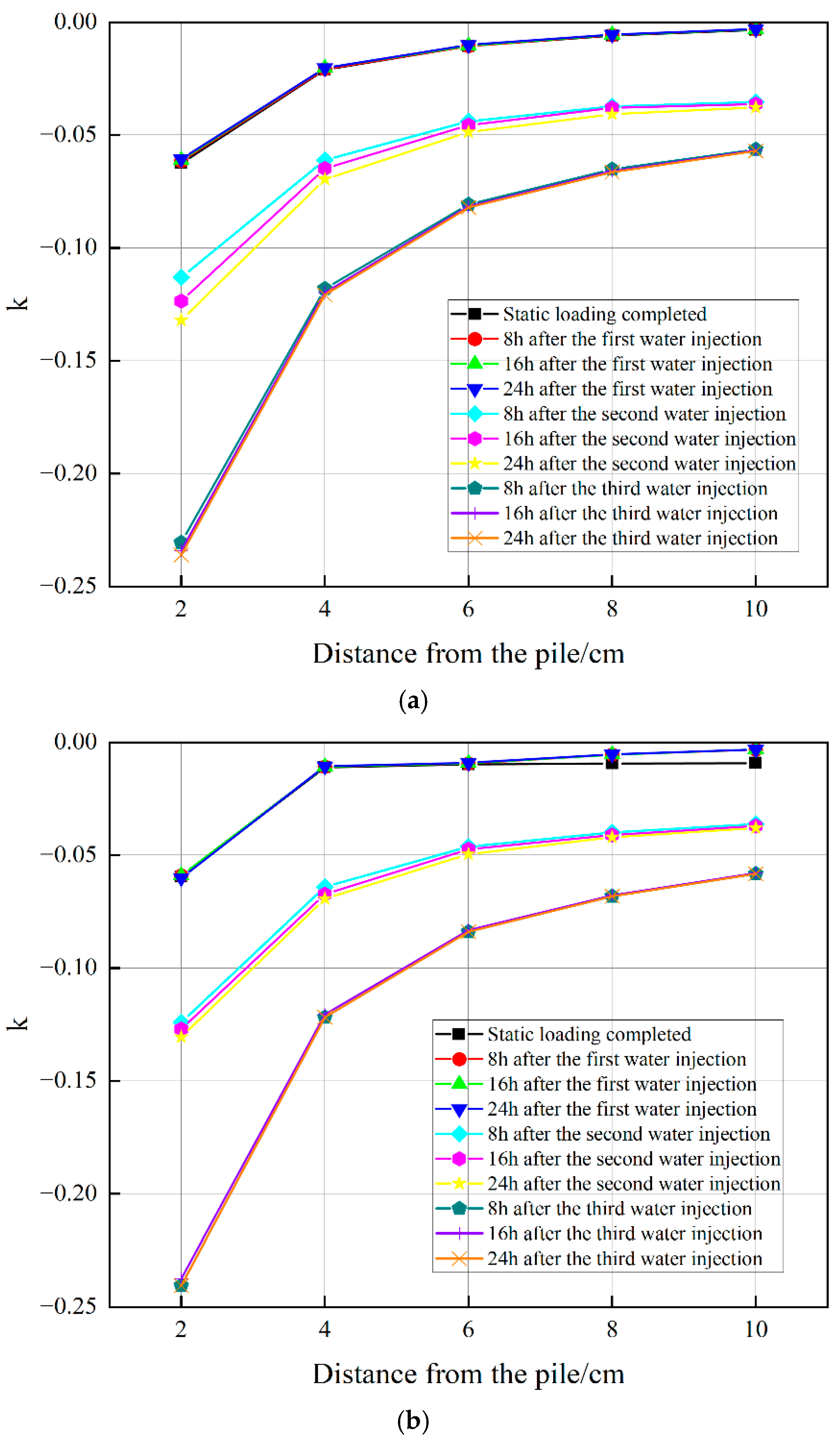
4.4. Change of Foundation Soil Settlement with the Immersion Time

Figure 20 and Figure 21 illustrate the settlement curves of the foundation soil around the piles under loads of 1.25 kN and 2.5 kN, respectively. Throughout the gradual rise of the groundwater, the settlement patterns of the foundation soil closely align with those of the pile foundation. During the initial phase from the completion of loading until 24 h after the first water injection, the soil settlement remains relatively constant. Following the second water injection, the collapsibility of the artificial loess leads to a marked increase in foundation soil settlement. Furthermore, capillary action prolongs this settlement even after water injection ceases. Subsequent to the third water injection, the complete collapse of the artificial loess results in the foundation soil settlement trending toward stabilization.
Figure 22 and Figure 23 present the change curves of the influence coefficient of the pile foundation on the foundation soil under upper loads of 1.25 kN and 2.5 kN, respectively, as calculated using Equation (3). Analogous to conditions without groundwater, the absolute value of the influence coefficient diminishes rapidly within a radial distance of D to 3D from the pile, although the rate of change is less pronounced beyond 3D. Consequently, it can be inferred that during the rise in groundwater level, the effective influence range of the pile foundation on the surrounding soil remains approximately 3D.

5. Conclusions

In this study, static load tests on pile foundations were carried out under two distinct conditions: without groundwater and with rising groundwater levels, using artificial collapsible loess and a model pile. The research focused on exploring the impact of rising groundwater on various aspects of pile foundation behavior, including settlement, axial force, skin friction, pile tip force, and settlement of foundation soil. The key findings are summarized as follows:
(1) The load–settlement curve of pile foundations is segmented into three distinct stages: the elastic stage, rapid development stage, and failure stage, with the ultimate bearing capacity of the pile foundations being 5 kN. When the groundwater level remains within the bearing layer, the settlement of the pile foundations is essentially unchanged. However, when the groundwater level reaches the artificial collapsible loess layer, there is a significant increase in settlement. Furthermore, this settlement continues to escalate even after ceasing the water injection, due to the effects of capillary action. Ultimately, the settlement of the pile foundation peaks and gradually stabilizes once the artificial loess layer is fully saturated.
(2) In the absence of underground water, the axial force along the pile shaft decreases progressively with depth, while the skin friction remains positive. The axial force and skin friction stabilize when the groundwater level is confined within the bearing layer. However, as the groundwater ascends to the artificial collapsible loess stratum, the axial force amplifies due to increased negative skin friction at the upper part of the pile shaft. Following the cessation of water injection, the magnitude of the negative skin friction continues to escalate due to capillary action, although the neutral point remains static. As the artificial loess fully collapses, the absolute value of the negative skin friction surges significantly, and the neutral point shifts downward.
(3) The initial bearing type of the model pile is identified as a friction pile. As the upper load increases, the bearing ratio contributed by skin friction diminishes, thereby directing the evolution of the pile foundations towards an end-bearing type. When groundwater penetrates the artificial collapsible loess layer, there is a significant reduction in the load-bearing ratio of the skin friction. Once the groundwater fully saturates the soil layer, the pile foundations predominantly transition to an end-bearing pile.
(4) In the absence of groundwater, the settlement of foundation soil initially increases and then decreases as the upper load increases, reaching a turning point at the allowable bearing capacity of the foundation. The influence range of the pile foundation on the soil settlement is three times the pile diameter. After the collapse of the artificial loess due to groundwater activity, the settlement of the foundation soil begins to increase markedly, surpassing that of the pile foundation itself. Even under these conditions, the influence range of the pile foundations on the soil settlement remains consistently at three times the pile diameter. Therefore, the foundation soil within this range should be treated with an emphasis on preventing the decrease in bearing capacity. The foundation treatment methods include compaction piles, chemical consolidation, etc. The artificial loess employed in this study does not replicate the stratification, cementation, and other structural characteristics of natural loess. Moreover, the inability to scale down soil particle size leads to discrepancies in permeability, strength, and deformation when compared with natural loess. Additionally, scaling influences the stress field, which consequently affects test outcomes. Given these factors, it becomes necessary to refine the research conclusions using numerical simulations and field tests to account for potential errors.

Author Contributions

Conceptualization, X.R., M.L., H.L. (Hongjian Liao) and Z.W.; Methodology, X.R., H.L. (Hongjian Liao), A.Z. and H.L. (Hangzhou Li); Formal analysis, T.D.; Investigation, A.Z. and T.D.; Resources, X.R.; Data curation, X.R. and M.L.; Writing—original draft, M.L.; Writing—review & editing, H.L. (Hongjian Liao) and H.L. (Hangzhou Li). All authors have read and agreed to the published version of the manuscript.

Funding

This research was funded by Qin Chuangyuan Scientist-Engineer Team Construction Project of Shaanxi Province in China (grant number 2023KXJ-178), National Natural Science Foundation of China (grant number 41630639 and 51879212), Key Research and Development Project of Shaanxi Province in China (grant number 2019KWZ-09).

Data Availability Statement

The original contributions presented in this study are included in the article. Further inquiries can be directed to the corresponding author.

Conflicts of Interest

Authors Xuewen Rong, Tao Dang and Zheng Wu were employed by the company Shaanxi Huashan Road and Bridge Group Co., Ltd. The remaining authors declare that the research was conducted in the absence of any commercial or financial relationships that could be construed as a potential conflict of interest.

References

  1. Weng, X.; Hu, J.; Mu, X.; Niu, H.; Huang, X. Model test study on the influence of the collapsibility of loess stratum on an urban utility tunnel. Environ. Earth Sci. 2022, 82, 32–48. [Google Scholar] [CrossRef]
  2. Wang, X.; Lu, H.; Zhang, H.; Wu, J.; Hou, X. Distribution, provenance, and onset of the Xiashu Loess in Southeast China with paleoclimatic implications. J. Asian Earth Sci. 2018, 155, 180–187. [Google Scholar] [CrossRef]
  3. Zhou, Y.; Yu, B.; Fan, W.; Dijkstra, T.A.; Wei, Y. 3D characterization of localized shear failure in loess subject to triaxial loading. Eng. Geol. 2023, 322, 107174. [Google Scholar] [CrossRef]
  4. Shen, Y.; Yan, H.; Wang, R.; Song, P.; He, Y. Review: Progress with Functional Materials Based on Loess Particles. Clays Clay Miner. 2021, 69, 301–314. [Google Scholar] [CrossRef]
  5. Munir, M.; Mujtaba, H.; Usama, K.; Khalid, F.; Zia, U. Study on Sustainable Utilization of CKD for Improvement of Collapsible Soil. Arab. J. Sci. Eng. 2023, 48, 5667–5682. [Google Scholar]
  6. Chai, Q.; Chen, T.; Li, Z.; Shen, D.; Wu, C. Experimental Study on the Negative Skin Friction of Piles in Collapsible Loess. Sustainability 2023, 15, 8893. [Google Scholar] [CrossRef]
  7. Li, P.; Vanapalli, S.; Li, T. Review of collapse triggering mechanism of collapsible soils due to wetting. J. Rock Mech. Geotech. Eng. 2016, 8, 256–274. [Google Scholar] [CrossRef]
  8. Wang, L.; Shao, S.; She, F. A new method for evaluating loess collapsibility and its application. Eng. Geol. 2020, 264, 105376. [Google Scholar] [CrossRef]
  9. Wang, M. Study on Structure of Collapsible Loess in China; Taiyuan University of Technology: Taiyuan, China, 2010. (In Chinese) [Google Scholar]
  10. Zhang, Y.; Hu, Z.; Chen, H.; Xue, T. Experimental Investigation of the Behavior of Collapsible Loess Treated with the Acid-addition Pre-soaking Method. KSCE J. Civ. Eng. 2018, 22, 4373–4384. [Google Scholar] [CrossRef]
  11. Zhu, Y.; Jia, X.; Shao, M. Thickness Variations Across the Loess Plateau of China. Surv. Geophys. 2018, 39, 715–727. [Google Scholar] [CrossRef]
  12. Li, Y.; Liu, W.; Guo, X.; Pan, Z.; Li, Y. Spatial-temporal distribution and variation characteristics of precipitation in China during 1956–2016. Adv. Water Sci. 2025, 36, 1–17. (In Chinese) [Google Scholar]
  13. Yao, Y.; Zhang, M.; Deng, Y.; Dong, Y.; Wu, X. Evaluation of environmental engineering geology issues caused by rising groundwater levels in Xi’an, China. Eng. Geol. 2021, 294, 106350. [Google Scholar] [CrossRef]
  14. Zhang, Y.; Liang, D. Analysis of dynamic characteristics of groundwater level in Xi’an during 33 years. Groundwater 2018, 40, 66–67. (In Chinese) [Google Scholar]
  15. He, X.; Tao, F.; Tao, H.; Ding, J.; Li, H. Analysis on Groundwater Level Variation Regulation of Guanzhong Plain and Its Influencing Factors. Groundwater 2015, 37, 52–54. (In Chinese) [Google Scholar]
  16. Zhang, J.; Chen, X.; Li, J.; Zhang, C. Research on the Slurry Diffusion and Load-Bearing Characteristics of Postgrouted Piles in Loess Areas. Int. J. Geomech. 2024, 24. [Google Scholar] [CrossRef]
  17. Xue, Z.; Zhang, Y.; Luo, J.; Yan, C.; Emmanuel, M.; Jia, X. Analysis of compressive strength, durability properties, and micromechanisms of solidified loess using industrial solid waste: Slag–white mud–calcium carbide residue. J. Build. Eng. 2024, 84, 108511. [Google Scholar] [CrossRef]
  18. Qian, C.; Li, M.; Liao, H.; Zhang, C.; Li, H. Research on the Vibration Fatigue Characteristics of Ancient Building Wood Materials. Buildings 2024, 14, 2840. [Google Scholar] [CrossRef]
  19. Adbullah, R.; Xavier, B.; Namgung, H.; Varghese, V.; Fujiwara, A. Managing transit-oriented development: A comparative analysis of expert groups and multi-criteria decision making methods. Sustain. Cities Soc. 2024, 115, 105871. [Google Scholar]
  20. Cao, Z.; Zhang, H.; Geng, J.; Tian, Z.; Sun, Y. Research on traffic accessibility of transit-oriented development of urban high-speed beltway service area: Take Qujiang service area as an example. J. Xi’an Univ. Archit. Technol. (Nat. Sci. Ed.) 2023, 55, 827–833+839. (In Chinese) [Google Scholar]
  21. He, L.; Xu, H.; Tang, B.; Liu, Q.; Tu, Q. Analysis of Vibration Test of Over-track Buildings in Different Areas of Depots. Noise Vib. Control. 2024, 44, 235–241. [Google Scholar]
  22. Jin, B. Mechanical Analysis and Optimization of Variable Mobile Trolley Bracket Based on Modular Construction of Upper Cover Plate of Metro Vehicle Section; Shijiazhuang Tiedao University: Shijiazhuang, China, 2024. [Google Scholar]
  23. Feng, Q.; Zhang, Y.; Jiang, J.; Wang, Z.; Lei, X. Field measurement and evaluation of vibration in different areas of a metro depot. Earthq. Eng. Eng. Vib. 2022, 21, 529–542. [Google Scholar]
  24. Chen, Y.; Feng, Q.; Liu, Q.; Jiang, J. Experimental study on the characteristics of train-induced vibration in a new structure of metro depot. Environ. Sci. Pollut. Res. Int. 2021, 28, 41407–41422. [Google Scholar] [CrossRef] [PubMed]
  25. Sun, W.; Zhu, H.; Yan, S.; Liang, Q.; Zhang, J. Seismic Fragility Analysis of Shallow-Buried Subway Station Structure in Loess Strata. J. Southwest Jiaotong Univ. 2025, 1–9. Available online: https://link.cnki.net/urlid/51.1277.U.20240219.1015.002 (accessed on 12 April 2025). (In Chinese).
  26. Xu, W.; Liu, Y.; Huang, Q.; Liu, X.; Zhao, C. Influence of Combination Types on Vibration Response of Superstructure of Subway Station. J. Southwest Jiaotong Univ. 2024, 59, 653–662. (In Chinese) [Google Scholar]
  27. Peng, H.; Pang, F.; Li, Z.; Xiao, X.; Tang, S. Study on the Impact of a Metro Depot Cover Structure on the Existing Metro Structure and Additional Settlement of Tracks. Buildings 2023, 13, 1914. [Google Scholar] [CrossRef]
  28. Ding, P.; Tao, L.; Yang, X.; Zhao, J.; Shi, C. Force Transfer and Deformation Mechanism of Single Ring Structure of Prefabricated Subway Station. J. Southwest Jiaotong Univ. 2020, 55, 1076–1084+1110. (In Chinese) [Google Scholar]
  29. Mu, Q.; Dai, B.; Zhou, C.; Meng, L.; Zheng, J. A new and simple method for predicting the collapse susceptibility of intact loess. Comput. Geotech. 2023, 158, 105408. [Google Scholar] [CrossRef]
  30. Liu, X.; Li, M.; Liao, H.; Huang, B.; Liu, S. Mechanical Properties of Adjacent Pile Bases in Collapsible Loess under Metro Depot. Appl. Sci. 2024, 14, 5819. [Google Scholar] [CrossRef]
  31. Chen, Y.; Li, X.; Huang, R.; Huang, L.; Li, L. Micro experimental research on influence factors of loess collapsibility. J. Eng. Geol. 2015, 23, 646–653. (In Chinese) [Google Scholar]
  32. Gu, T.; Wang, J.; Guo, L.; Chu, D.; Li, K. Study of Q3 loess microstructure changes based on image processing. Chin. J. Rock Mech. Eng. 2011, 30, 3185–3192. (In Chinese) [Google Scholar]
  33. Assallay, A.M.; Jefferson, I.; Rogers, C.D.F.; Smalley, I.J. Fragipan formation in loess soils: Development of the Bryant hydroconsolidation hypothesis. Geoderma 1998, 83, 1–16. [Google Scholar] [CrossRef]
  34. Assallay, A.M.; Rogers, C.D.F.; Smalley, I.J. Formation and collapse of metastable particle packings and open structures in loess deposits. Eng. Geol. 1997, 48, 101–115. [Google Scholar] [CrossRef]
  35. Jefferson, I.; Ahamd, M. Formation of Artificial Collapsible Loess. In Problematic Soils and Rocks and In Situ Characterization; ASCE Press: Reston, VA, USA, 2012; pp. 1–10. [Google Scholar]
  36. JGJ 94-2008; Technical Code for Building Pile Foundations. MoHURD: Beijing, China, 2008. (In Chinese)
  37. JGJ 106-2014; Technical Code for Testing of Building Foundation Piles. MoHURD: Beijing, China, 2014. (In Chinese)
  38. Zhang, Y. Research on Engineering Properties of Artificial Prepared Collapsible Loess and Calculation Method of Vertical Bearing Capacity of Deep Foundation; Lanzhou Jiaotong University: Lanzhou, China, 2017. (In Chinese) [Google Scholar]
  39. Tian, J. Research on Vertical Bearing Characteristics of Necking Pile Based on Load Transfer Method; Henan University of Technology: Zhengzhou, China, 2024. (In Chinese) [Google Scholar]
Figure 1. Materials for preparing artificial collapsible loess.
Buildings 15 01341 g001
Figure 2. The preparation of the samples by free-drop method.
Buildings 15 01341 g002
Figure 3. The remolded soil of non-collapsible loess.
Buildings 15 01341 g003
Figure 4. Model box and loading system.
Buildings 15 01341 g004
Figure 5. Preparation processes of model pile foundations.
Buildings 15 01341 g005
Figure 6. Layout drawing of pile foundations. (a) Front view. (b) Top view.
Buildings 15 01341 g006
Figure 7. Data-collecting devices.
Buildings 15 01341 g007
Figure 8. The setting of groundwater level.
Buildings 15 01341 g008
Figure 9. Load–settlement curve of pile foundations without groundwater.
Buildings 15 01341 g009
Figure 10. Axial force of the pile foundations without groundwater.
Buildings 15 01341 g010
Figure 11. Skin friction of the pile foundations without groundwater.
Buildings 15 01341 g011
Figure 12. Change curve of pile tip force and its bearing ratio without groundwater.
Buildings 15 01341 g012
Figure 13. Change curve of settlement amount of foundation soil without groundwater. (a) L1~L5. (b) R1~R5.
Buildings 15 01341 g013
Figure 14. Influence coefficient of pile foundation on foundation soil without groundwater. (a) L1~L5. (b) R1~R5.
Buildings 15 01341 g014
Figure 15. Settlement curve of pile foundations during groundwater rising.
Buildings 15 01341 g015
Figure 16. Axial force distribution of pile foundations during groundwater rising. (a) The upper load is 1.25 kN. (b) The upper load is 2.5 kN.
Buildings 15 01341 g016
Figure 17. Skin friction distribution of pile foundations during groundwater rising. (a) The upper load is 1.25 kN. (b) The upper load is 2.5 kN.
Buildings 15 01341 g017
Figure 18. Changing curve of pile tip force during groundwater rising. (a) The upper load is 1.25 kN. (b) The upper load is 2.5 kN.
Buildings 15 01341 g018
Figure 19. Changing curve of bearing ratio during groundwater rising. (a) The upper load is 1.25 kN. (b) The upper load is 2.5 kN.
Buildings 15 01341 g019
Figure 20. Foundation soil settlement under 1.25 kN load during groundwater rising. (a) L1~L5. (b) R1~R5.
Buildings 15 01341 g020
Figure 21. Foundation soil settlement under 2.5 kN load during groundwater rising. (a) L1~L5. (b) R1~R5.
Buildings 15 01341 g021
Figure 22. Influence coefficient of foundation soil under 1.25 kN load during groundwater rising. (a) L1~L5. (b) R1~R5.
Buildings 15 01341 g022
Figure 23. Influence coefficient of foundation soil under 2.5 kN load during groundwater rising. (a) L1~L5. (b) R1~R5.
Buildings 15 01341 g023
Table 1. Physical properties of artificial loess and non-collapsible loess.
Physical PropertiesSpecific RatioOptimum Moisture Content/%Void RatioLiquid Limit/%Plastic Limit/%
Artificial collapsible loess2.72121.1225.515.4
Non-collapsible loess2.71160.6326.817.5
Table 2. Mechanical properties of artificial loess and non-collapsible loess.
Mechanical PropertiesCompression Modulus/MPaCohesion/kPaInternal Friction Angle/°
Artificial collapsible loess4.1624.723.2
Non-collapsible loess6.5233.428.7
Table 3. Collapsible coefficients of artificial loess.
Pressure50 kPa100 kPa200 kPa300 kPa
Collapsible coefficient0.0750.0820.0880.089
Table 4. Material parameters of plexiglass.
Elastic Modulus/MPaPoisson’s RatioGravity/(kN/m3)
33000.212
Disclaimer/Publisher’s Note: The statements, opinions and data contained in all publications are solely those of the individual author(s) and contributor(s) and not of MDPI and/or the editor(s). MDPI and/or the editor(s) disclaim responsibility for any injury to people or property resulting from any ideas, methods, instructions or products referred to in the content.

