Article

Jacking Force Prediction for Long-Distance Pipe by Integrating Physical Information and Adversarial Learning Mechanism

1
School of Water Conservancy, North China University of Water Resources and Electric Power, Zhengzhou 450046, China
2
College of Surveying and Geo-Information, North China University of Water Resources and Electric Power, Zhengzhou 450046, China
3
Henan Water Conservancy Engineering First Group Co., Ltd., Zhengzhou 450000, China
*
Authors to whom correspondence should be addressed.
Buildings 2025, 15(8), 1337; https://doi.org/10.3390/buildings15081337
Submission received: 1 April 2025 / Revised: 8 April 2025 / Accepted: 16 April 2025 / Published: 17 April 2025
(This article belongs to the Section Building Structures)

Abstract

Accurate prediction of jacking force is crucial for long-distance pipe jacking construction. This study establishes a theoretical jacking force model considering the soil pressure arch effect, where the Persson contact model and the hydrodynamic parallel plate model are incorporated to accurately characterize pipe–soil friction and lubrication resistance, resulting in more reliable friction force estimation as confirmed by field measurements. To enhance prediction accuracy, a Physics-Informed Domain Adversarial Training Neural Network (PIDANN) is proposed, integrating physical constraints into neural network training and expanding the dataset with theoretical values. A case study on the Zheng-Kai city water supply project demonstrates that (1) the theoretical model improves friction force predictions by incorporating the pressure arch effect; (2) PIDANN achieves superior prediction accuracy compared to models without adversarial training; (3) the two fusion methods of physical information integration reduce the mean squared error (MSE) by 36.9% and 20.2%, enhancing generalization and reducing overfitting risks. These findings provide valuable guidance for jacking force control in pipe jacking construction.

1. Introduction

With the rapid development of infrastructure networks, such as water supply and power supply systems, the use of underground pipeline construction has increased significantly. The pipe jacking method, a trenchless pipeline installation technique, offers numerous advantages, including enhanced safety, high efficiency, minimal ground disturbance, and strong adaptability to varying geological conditions. As a result, it has become increasingly popular in underground pipeline projects, particularly for pipeline installations beneath highways, railroads, rivers, and buildings, where it is often the preferred method [1,2].
In pipe jacking projects, the jacking force is a critical parameter that affects the selection of jacking equipment, operational arrangements, and the design of intermediate jacking stations. It is also a key control factor in the construction process; both excessive and insufficient jacking forces can lead to safety risks [3]. Currently, most theoretical models for calculating jacking force are based on the pipe–soil full-contact and partial-contact models, derived from the stabilization assumption of dug-in tunnels proposed by Haslem [4]. For example, O’Reilly et al. proposed a formula for calculating pipe–soil friction resistance based on the assumption of full pipe–soil contact and soil pressure theory [5]. Bennett further developed a model incorporating pressure arch discounting coefficients and resistance reduction factors at different lubricant stages [6]. In addition, the pipe–soil full-contact model is used in Chinese construction codes such as Chinese GB 50268-2008 to calculate the friction component of the jacking force [7].
Beyond the pipe–soil full-contact model, several scholars have proposed partial-contact jacking force models based on different theoretical approaches. These include the model incorporating friction due to the self-weight of the pipe [8], the pipe–soil elastic contact model [4], and the combined pipe–soil and slurry friction model [9], among others. While these knowledge-driven models establish explicit causal relationships, they struggle with the nonlinearities and uncertainties present in complex construction contexts [10]. Furthermore, while these models offer acceptable accuracy for short-distance jacking, they often yield significant errors when applied to long-distance projects [11].
In recent years, data-driven machine learning methods have been increasingly applied in construction engineering [12]. Deep learning techniques have demonstrated exceptional capabilities in capturing complex relationships in civil engineering applications, maintaining robust performance even under varying environmental conditions [13]. Furthermore, deep learning frameworks excel in handling uncertainty, effectively modeling nonlinear relationships, and enabling accurate predictive reasoning [14]. Machine learning-based artificial intelligence methods have been successfully applied to various aspects of pipe jacking projects, such as predicting receiving shaft settlement [15], rectangular pipe jacking settlement [16], construction parameter optimization [17], and underwater curved pipe jacking force prediction [18]. Additionally, the applicability of machine learning models beyond specific working conditions or engineering datasets remains a key concern for researchers and practitioners [19]. Traditional machine learning models often struggle with limited generalizability, as their predictive performance deteriorates when applied to new construction environments with different soil conditions, operational parameters, or external disturbances. To address this challenge, Domain Adversarial Training of Neural Networks (DANN), proposed by Ganin et al. [20], offers a promising solution by enabling the adaptation of machine learning models across different datasets. By leveraging adversarial training, DANN aligns feature distributions between source and target domains, thereby enhancing the model’s ability to generalize to unseen projects with varying construction conditions.
Beyond improving model adaptability, integrating physical principles, prior knowledge, and expert input into machine learning models can enhance interpretability and align results with theoretical expectations [21,22]. The knowledge data fusion modeling method has achieved exciting results and has gained increasing attention as a way to overcome the limitations of purely empirical models [23]. Specifically, Raissi et al. introduced Physics-Informed Neural Networks (PINNs) [24], which integrate physical laws governing the research object with measured data, combining knowledge-driven and data-driven approaches. PINNs have been successfully applied in areas such as unsteady temperature field prediction, Burgers-Fisher equation solving, structural vibration analysis, and fatigue crack propagation [25,26,27,28]. However, their application in engineering construction remains limited.
Jacking force, the force required to overcome friction during pipe jacking construction, is influenced by various factors such as soil conditions, pipe–soil interaction, and drag reduction measures. It follows inherent physical mechanisms, making accurate prediction a challenging yet essential task. This study develops a dual-driven Physics-Informed Domain Adversarial Neural Network (PIDANN) model, which integrates theoretical physical models with engineering data through a machine learning approach. The innovation of this framework lies in the dual fusion strategy: (1) incorporating physics-based constraints derived from theoretical friction models into the neural network training process and (2) augmenting the input features with theoretically calculated values. These two mechanisms jointly strengthen the model’s consistency with physical laws and enhance prediction stability. The proposed framework combines Domain Adversarial Neural Network (DANN) with physics-informed constraints to enhance model interpretability and promote generalization, offering a potential solution to typical challenges faced in engineering-oriented AI tasks.
To evaluate the effectiveness of the PIDANN model, this study applies it to engineering data collected from three construction sites. The model’s performance is compared against baseline methods, non-transfer learning approaches, and models without adversarial training. The overall study framework and methodological process are detailed in Section 2.1, where the integration of physical models with machine learning techniques is systematically explained.

2. Methods

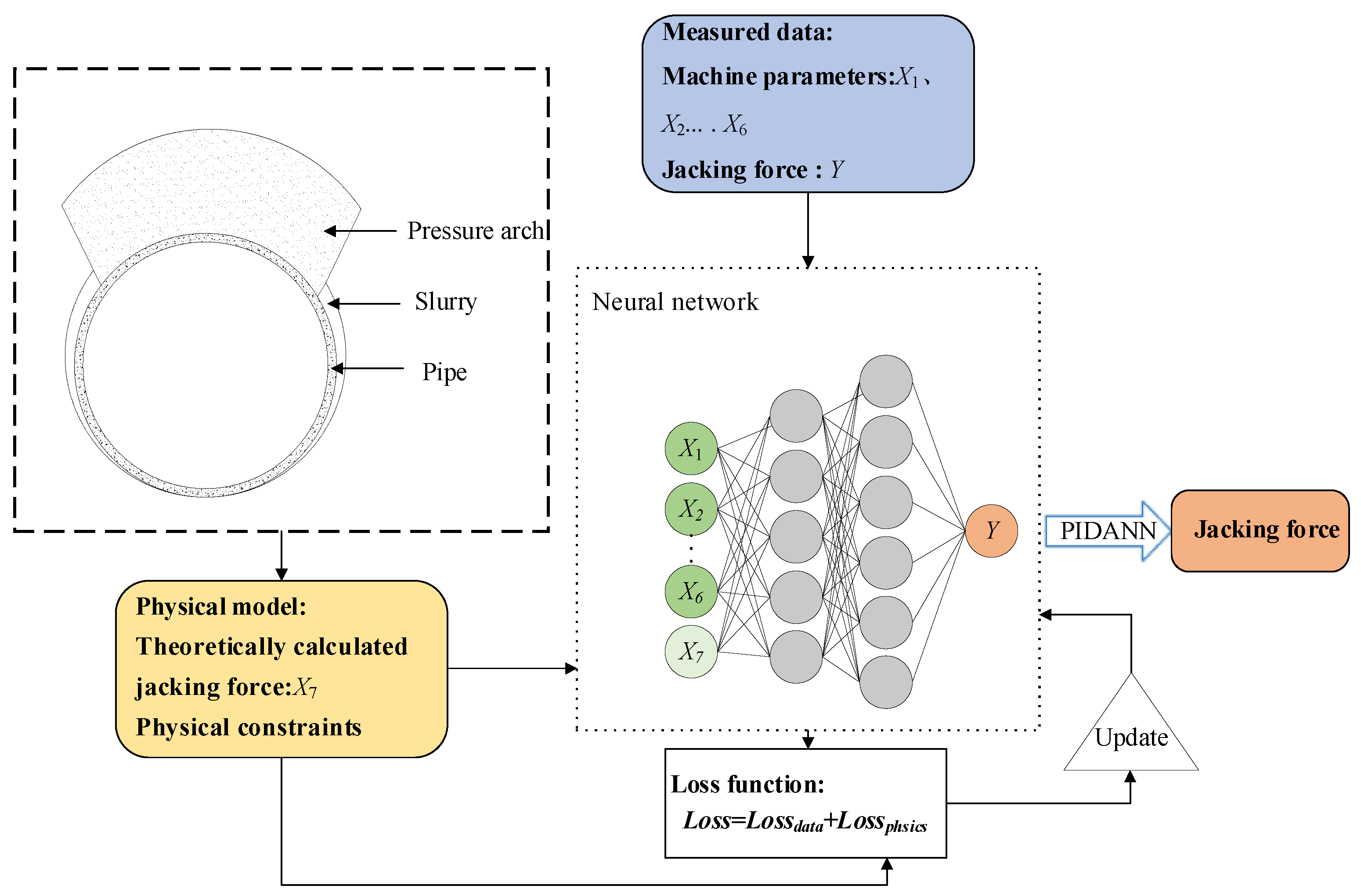
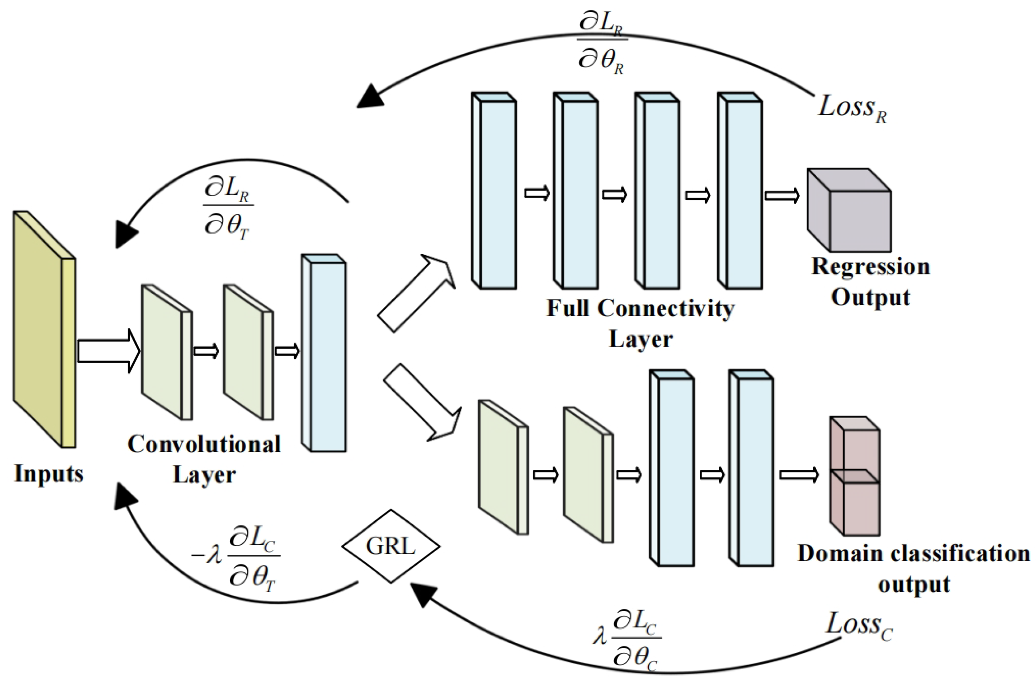
2.1. The Framework of PIDANN for Pipe Jacking Force

In this section, the research framework adopted in this study is introduced in detail to systematically illustrate the process of predicting the jacking force in long-distance pipe jacking construction. The overall framework is shown in Figure 1, which encompasses the development of theoretical models, the integration of physical mechanism constraints, and the construction and application of neural network models based on DANN.
Figure 1. Overall framework for jacking force prediction in long-distance pipe jacking construction.
Buildings 15 01337 g001
Firstly, by considering the soil pressure arch effect, a theoretical calculation model for the jacking force was developed, incorporating the coordinated surface Persson contact model and the hydrodynamic parallel plate model. Secondly, two fusion methods were proposed based on the DANN. The one is introducing physical mechanism constraints into the neural network training process, and the other is expanding the input dataset with theoretical values. Finally, these approaches were combined to construct the Physics-Informed Domain Adversarial Neural Network (PIDANN) for jacking force prediction. The modules and flowcharts presented in Figure 2 clearly illustrate the logical relationships and interactions among these steps, providing structured guidance for the computational analysis and case studies that follow.
Figure 2. Process flow of PIDANN: integration of theoretical model and domain adversarial training.
Buildings 15 01337 g002

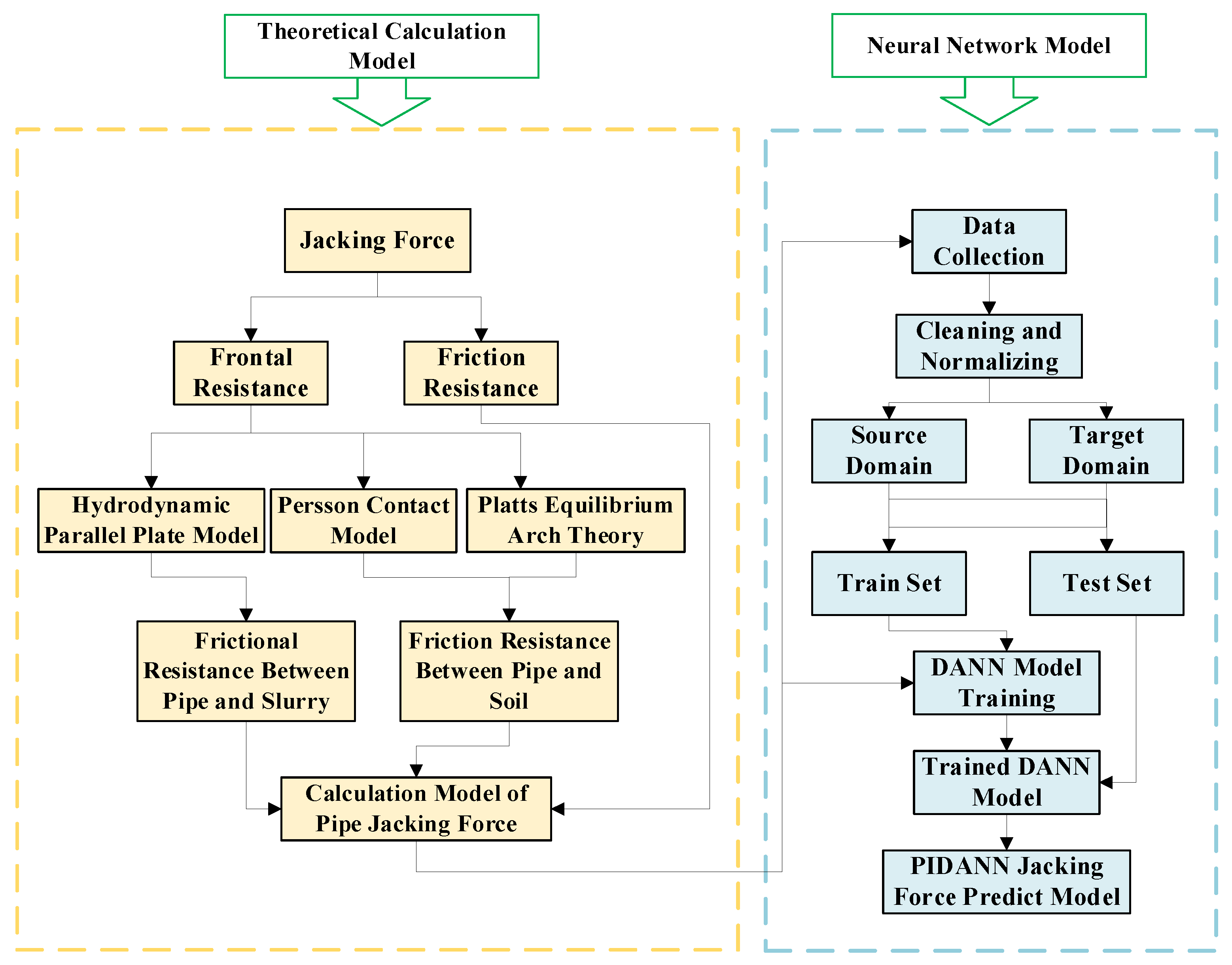
2.2. Theoretical Calculation Model of Pipe Jacking Force

The calculation of the jacking force in pipe jacking construction involves two main components: pipe–soil friction resistance and the frontal resistance exerted by the pipe jacking machine’s cutterhead. The total jacking force can be expressed as follows:
F = F f + F n
F f = F f 1 + F f 2
F n = γ H π 4 D 2
where F f is the jacking frictional resistance (kN); F f 1 is the pipe–soil frictional resistance (kN); F f 2 is the pipe slurry frictional resistance (kN); F n is the cutterhead frontal resistance (kN); γ is the average unit weight of overlying soil (kN/m3); H is the depth of cover (m); D is the pipe diameter (m).
Pipe–soil friction resistance increases with the distance of jacking, while the cutterhead’s frontal resistance is generally assumed to be constant. Among these components, the pipe–soil friction resistance is the dominant factor in determining the overall jacking force. In this study, assuming partial contact between the pipe and the surrounding soil, and accounting for the soil pressure arch effect as well as drag-reduction measures such as grouting and waxing, we utilize the Persson model and the parallel plate fluid power law model to calculate the frictional drag. Based on these models, the corresponding physical computation model for pipe jacking force is developed.

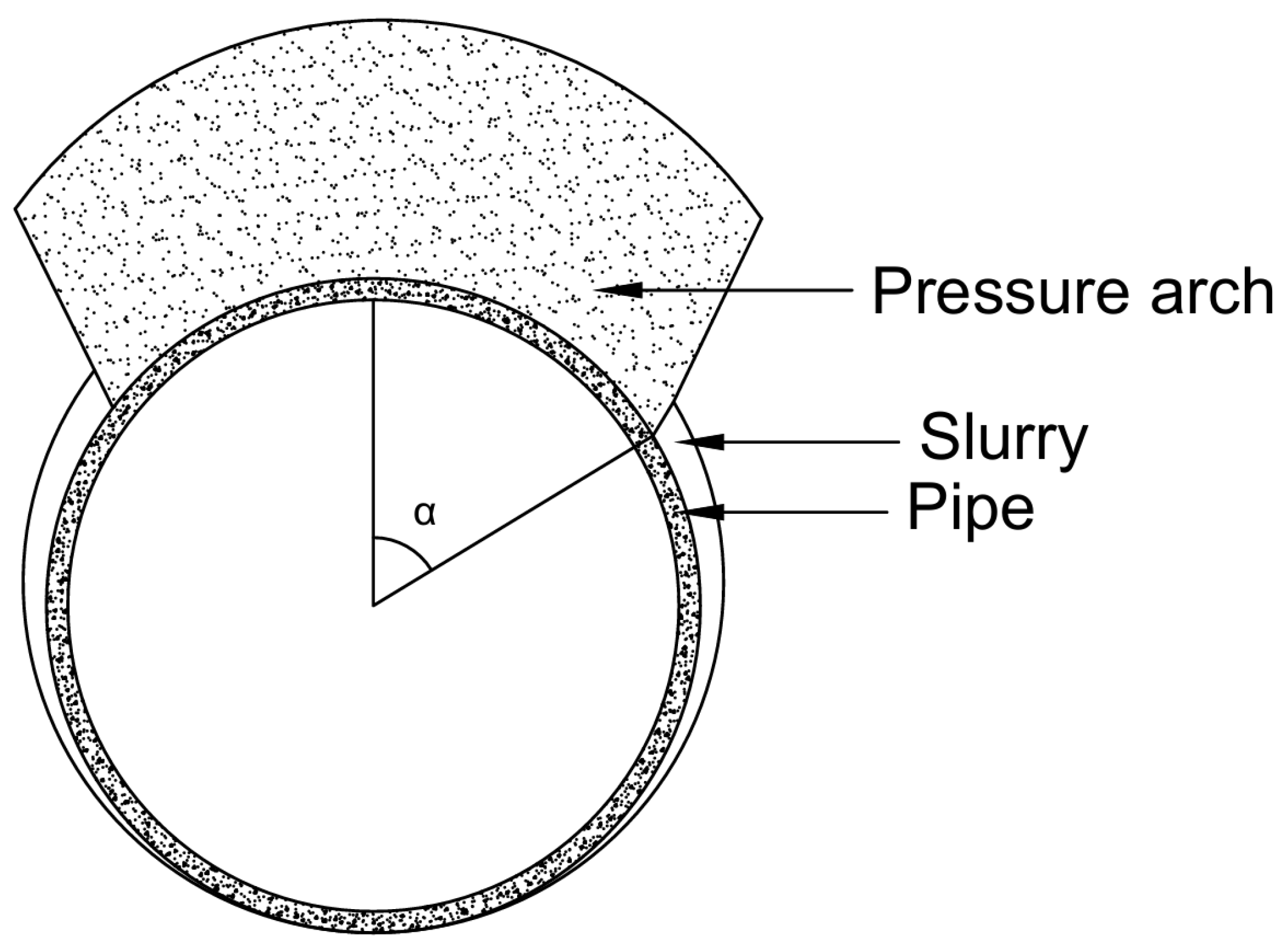
2.2.1. Calculation of Friction Resistance Between Pipe and Soil

Recent studies based on numerical simulations and field measurements have found that, under favorable geological conditions, a soil pressure arch is likely to form above the tunnel, resulting in a significant unloading effect [29,30]. These findings validate the rationality of evaluating vertical earth pressure by considering the arching effect, and support the incorporation of this mechanism into the theoretical modeling of jacking force. In this study, it is assumed that a pressure arch forms in the top soil when calculating the vertical earth pressure on the pipe body. The schematic diagram of the pressure arch model is shown in Figure 3. Based on Platts equilibrium arch theory, the disturbed soil collapses within a specific range and leads to the formation of a new equilibrium arch during excavation. As excavation progresses, the tunnel wall is only subjected to the forces from this new equilibrium arch, which causes unloading of the surrounding soil. The height of the arch and the vertical earth pressure can be calculated using the following formula:
h = b 1 f k
b 1 = D / 2 + D tan ( 45 ° φ / 2 )
F V = γ h = γ D / 2 + D tan ( 45 ° φ / 2 ) / f k
where h is the height of the pressure arch(m), b 1 is the distance from the center of the pipe to the edge of the pressure arch (m), φ is the in-soil friction angle, f k is the solid coefficient.
Figure 3. Cross-sectional view of the pipeline under the influence of the soil pressure arch.
Buildings 15 01337 g003
This study assumes that the soil above the pipe top will collapse incompletely and the collapsed part is determined by the width of the pressure arch and the radius of the pipe. To simplify the calculation, this study uses the pressure arch height of the pipe top to calculate the vertical earth pressure. Then, the normal force acting on the pipeline by the vertical earth pressure F V N and the friction resistance generated by the vertical earth pressure F f V are:
F V N = F V cos α
F f V = 2 μ 1 μ 2 0 β D 2 F V N d α
β = arctan b 1 D / 2
where μ 1 is the pipe–soil friction coefficient, μ 1 = tan ( φ / 3 ) [31], μ 2 is the wax-coating drag reduction factor, which is taken as 0.5, according to indoor test.
To calculate the pipe–soil friction resistance under partial contact conditions at the bottom of the pipe, it is crucial to determine both the pipe–soil contact pressure and the contact angle. While the Hertz contact model was originally used to calculate contact angle and contact pressure, the Persson contact model is more suitable for this application, given the minimal over excavation and relatively large contact area between the tunnel and the pipe during pipe jacking [32]. Due to the significantly lower elastic modulus of the soil compared to that of the pipe, the calculation of the contact angle and contact width using the Persson model can be further simplified as follows [33]:
π E s R 1 v s 2 F H + 1 2 V s 1 V s = 1 ln ξ 2 + 1 + 2 ξ 4 ξ 2 + 1 ξ 2
ξ = tan ε / 2
F H = F V + W F
b = 2 D ε
W = 2 π γ C R P t 0
F = π ρ 0 g R p 2
where ε is the pipe–soil contact angle (m), E S is the modulus of elasticity of the soil (Pa), V S is the Poisson’s ratio of the soil, R is the difference between the radius of the tunnel and the pipeline (m), F H is the unit length of the tube in the direction of the combined vertical force (kN/m), F V is the unit length of the tube subject to vertical soil pressure (kN/m), b is the pipe–soil contact width (m), W is the weight of the pipe per unit length (kN/m), F is the buoyancy force exerted by the slurry on the pipe per unit length (kN/m), γ C is the unit weight of concrete (kN/m3), R P is the radius of the pipe body (m), t 0 is the thickness of the pipe body (m), ρ 0 is the density of the slurry (kg/m3), and g is the gravitational acceleration (N/kg).
After determining the pipe–soil contact angle and the contact pressure distribution, the total pipe–soil contact pressure per unit length can be calculated using the following equation [34].
P = F H ε ε 1 2 π ( ξ 2 + 1 ) ξ 2 ln ξ 2 + 1 + ξ 2 e 2 ξ 2 + 1 + ξ 2 e 2 + 2 ξ 2 e 2 π ξ 2 + 1 ( 1 + e 2 ) d θ
e = tan ( θ / 2 )
The integral term following Formula (10) can be expressed as coefficient C. According to the analysis in [35], the error in calculating the pipe–soil contact angle and coefficient C under working conditions, with the Poisson’s ratio of the soil ranging from 0.2 to 0.4, does not exceed 5%. To simplify engineering calculations, the pipe–soil contact angle can be approximated as 180°, and the coefficient C can be taken as 1.35. The pipe–soil contact friction resistance is calculated as follows:
F f 1 = 1.35 μ 1 μ 2 F H + F f V

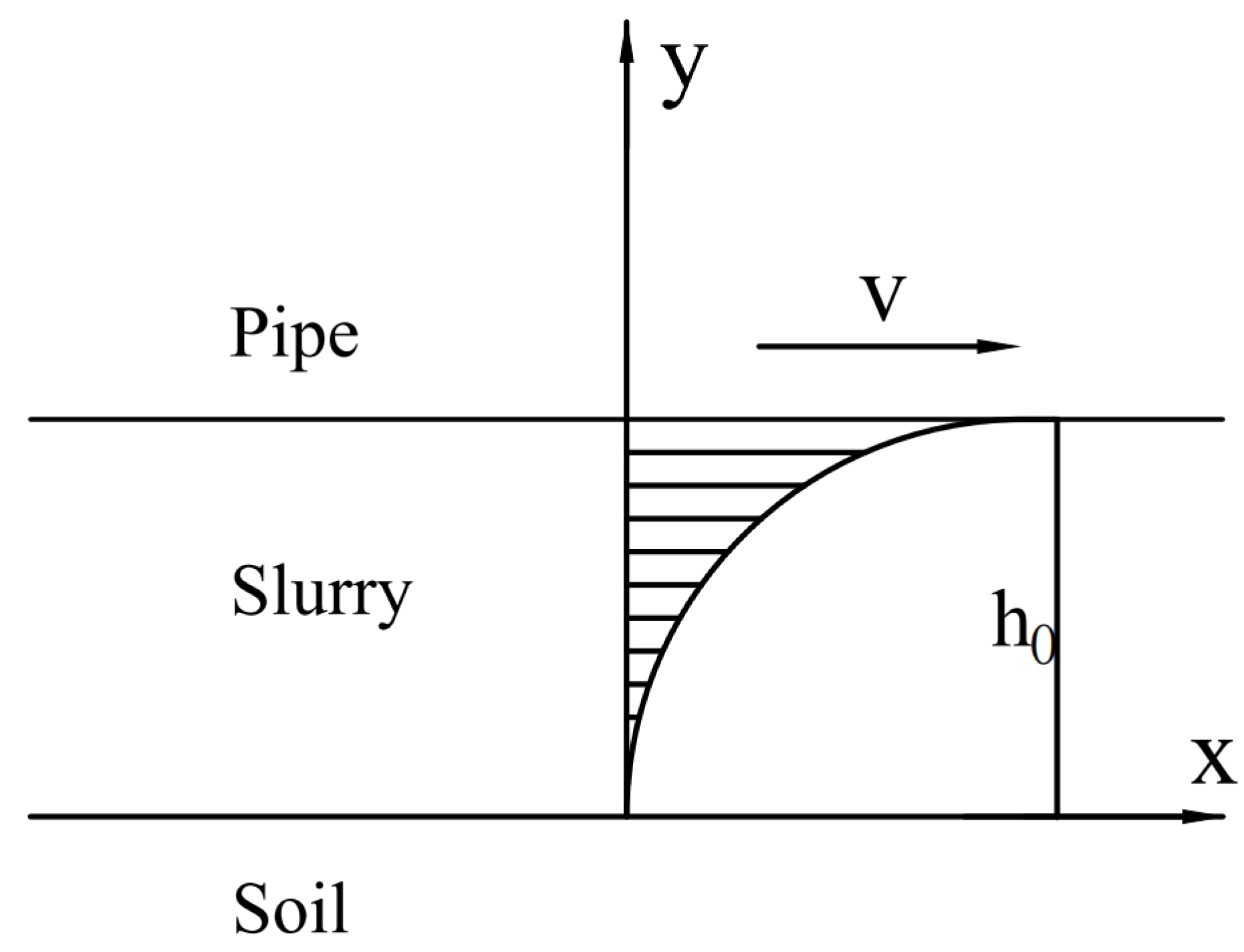
2.2.2. Calculation of Frictional Resistance Between Pipe and Slurry

Bentonite slurry exhibits notable thixotropic properties, enabling it to fill the gap between the tunnel face and the pipe body during pipe jacking. This process forms a continuous slurry jacket that reduces friction and provides structural support. During continuous jacking, significant relative displacement occurs between the slurry and the pipe. Under the shear forces exerted by the pipe, the slurry’s consistency decreases, transitioning into a more fluid-like state. As illustrated in Figure 4, the pipe–soil–slurry interaction model can be simplified to a hydrodynamic plate model, which is expressed as follows:
U = V h 0 y
where U is the velocity of the slurry (mm/s), V is the velocity of pipe jacking (mm/s), h 0 is the thickness of the slurry jacket (mm).
Figure 4. Schematic of the hydrodynamic plate model for pipe–soil interaction.
Buildings 15 01337 g004
To simplify the calculation, the following assumptions are made [36]:
The slurry jacket thickness is constant and is defined as h 0 = R S R P , where R S is the radius of the pipe jacking machine. The pipe moves at a uniform velocity, and the slurry velocity at the surface of the pipe is equal to the pipe jacking velocity. The effects of pressure and temperature on the slurry parameters are neglected. The slurry velocity U is assumed to be a function of the spatial coordinates y only.
Using the power-law model at atmospheric pressure, the shear stress between the pipe and the slurry is calculated as follows:
τ = K V h 0 N
where τ is the horizontal shear stress at the interface between the pipe and the slurry, K is the fluid consistency index, and N is the flow behavior index.
In summary, the frictional resistance between the pipe and the slurry can be calculated as follows:
F f 2 = τ π D b α D

2.2.3. Comparison of Models for Frictional Force Calculation

To verify the applicability of the friction force calculation model proposed in this paper, a comparison is made with the frictional force calculation models presented in the literature [6], literature [9], and Chinese GB 50268-2008. The results are shown in Table 1.
The construction parameters for the pipe jacking project case in this paper are defined as follows: R P = 1.65 m, R S = 1.68 m, V = 75 mm/min, h 0 = 0.03 m. The concrete pipe section parameters are as follows: γ c = 26.0 kN/m3, t 0 = 0.25 m. The slurry parameters are as follows: ρ 0 = 1.05 g/cm3, N = 0.5, K = 1.31 Pa·s1/2. Soil parameters were taken as the average value of each soil layer: E S = 7.4 MPa, V S = 0.35, φ = 30°, γ = 18.76 kN/m3, f k = 1.0, g = 9.8 N/kg.
Table 1. Comparison of theoretical model calculations of friction resistance.
ModelsThe Mean Frictional Force/kPa
Literature [6]4.61
Literature [9]2.69
GB 50268-20084
The proposed model2.07
Case Measurements1.42
As shown in Table 1, the calculation results of the model proposed in this paper are the closest to the measured values, with the smallest error. In contrast, the assumptions and parameter values used in the theoretical calculation models from references and industry standards are more conservative, leading to larger calculation results. Furthermore, on-site measurements using a vibrating wire sensor indicate that the soil pressure at monitoring points on the pipe crown is 89.42 kPa, approximately 61.4% of the conventional full-contact models. This substantial reduction supports the presence of a pressure arch effect—one of the key assumptions in our theoretical model. The unloading behavior observed under real-world conditions confirms the appropriateness of incorporating the unloading assumption into the model’s formulation. Although the scope of on-site measurement is limited, it provides important empirical evidence supporting the accuracy and physical relevance of the proposed theoretical framework.

2.3. Domain Adversarial Training of Neural Network

Jacking force prediction in pipe jacking construction is challenging due to variability in geological conditions, lubrication effects, and operational parameters across different working sections. Traditional machine learning models often suffer from poor generalization when applied to different pipeline sections because the data distributions differ significantly between sections, resulting in decreased predictive accuracy. To address this issue, we adopt Domain Adversarial Training of Neural Networks (DANN) to enhance model generalization across different construction environments. In the transfer learning framework, multi-source data are divided into a source domain dataset and a target domain dataset, which typically exhibit distributional discrepancies due to differences in soil conditions, pipe–soil interactions, and jacking force characteristics. The adversarial learning mechanism of DANN is employed to align these inconsistent distributions, enabling the model to learn domain-invariant features and improve predictive robustness. The network structure of the jacking force prediction model, based on DANN, is shown in Figure 5. It consists of three modules: a feature extractor, a domain discriminator, and a regressor. The source and target domain datasets are used as input, where the regressor generates jacking force predictions, the domain classifier distinguishes feature domain origins, and the feature extractor learns transferable feature representations through adversarial learning, thereby improving prediction accuracy across different working conditions. To further enhance interpretability and prevent overfitting, physics-informed constraints are incorporated into the model. Unlike purely data-driven models, which may lack physical consistency, the introduction of physics-based constraints ensures that the predicted jacking force adheres to fundamental physics principles. This approach not only improves generalization but also reduces overfitting risks by guiding the model toward physically meaningful solutions. To achieve domain adaptation, a Gradient Reversal Layer (GRL) is introduced between the feature extractor and the domain discriminator. During backpropagation, the GRL reverses the direction of the gradient, encouraging the feature extractor to learn features that are invariant to domain differences. This promotes alignment of feature distributions across different pipeline sections and improves the model’s adaptability to varying working conditions, thereby enhancing its reliability in practical engineering applications. The regressor consists of four fully connected layers, while the domain discriminator comprises two 1D convolutional layers followed by two fully connected layers. The feature extractor includes two 1D convolutional layers and one fully connected layer. To mitigate the risk of overfitting, a dropout layer with a dropout rate of 0.2 is added at the end of all three structures. A 1D convolutional layer can be expressed as follows:
Y i = j = 0 k 2 X i s + j K j + β
where Y represents the output, X is the padded input, denotes the current output index, k is the size of the convolution kernel, s is the stride of the convolution, K j is the j -th parameter of the convolution kernel, and β is the bias term.
Based on DANN, this paper proposes two methods for integrating physical information into neural networks:
(1) PIDANN I: Drawing on the modeling approach of the Physics-Informed Neural Network (PINN) [21], the jacking force calculation method proposed in Section 2.2 is incorporated as a physical constraint into the regressor loss. The specific method is as follows:
L o s s R = 1 n i = 1 n ( y ^ i y i ) 2 + ω 1 n i = 1 n ( y ^ i Y i ) 2
where L o s s R represents the regressor loss, y ^ is the predicted value, y is the measured value, Y is the theoretically calculated jacking force, n is the length of the sequence, ω is the weight of the physical constraint.
(2) PIDANN II: Expand the input feature set by incorporating the theoretically calculated jacking force as an input feature X i .
Figure 5. Architecture of the DANN model for jacking force prediction.
Buildings 15 01337 g005

3. Case Study

3.1. Project Overview

The total length of the water pipeline for the Zheng Kai City Demonstration Area Water Supply Pipe Jacking Project is 108.01 km, involving 141 pipe jacking sections with a total jacking length of approximately 38 km. The longest single jacking section reaches about 1.1 km. Among these, the 13th Street section is located in the northern part of the Huanghuai alluvial plain. The geological profile consists mainly of silt, fine sand, sandy loam, and powdery loam, forming a typical multi-layered clay–sand structure. The ground elevation ranges from 74.6 m to 77.9 m, while the groundwater depth varies between 4.1 m and 10.5 m, with a water level between 66.85 m and 70.7 m. Considering the physical characteristics of the soil layer, groundwater conditions, and jacking length, the mud-water balance pipe jacking method was selected to ensure construction safety and excavation face stability. This method is particularly effective in soft soil strata with high groundwater tables, where it can stabilize the excavation face by balancing earth and water pressure, thus minimizing the risks of collapse and water ingress.
The dataset used for model training and testing in this paper was collected from three sites: Working Shaft No. 1, No. 2, and No. 3. The basic information of the three working shaft sections is shown in Table 2.
Table 2. Overview of construction segments in the case project.
Shaft No. 1Shaft No. 2Shaft No. 3
Jacking lengths (m)1025629363
Average overburden depths (m)7.728.127.94
Working shaft pipe centerline elevation (m)67.669.865.1
Receiving shaft pipe centerline
elevation (m)
69.869.865.1
Soil layer typesilty loamsilty loampowdery clay

3.2. Data Collection and Preprocessing

During the pipe jacking construction process, the operating platform of the pipe jacking machine records seven key parameters: cutter current, cutter speed, mud discharge pressure, front cabin pressure, jacking speed, jacking distance, and jacking force. The first six parameters from the monitoring data of three working sections (Working Shaft No. 1, No. 2, and No. 3) were used as input features for the model, while the jacking force served as the output variable. The model was then trained and validated.
Data collection during construction is subject to various influences, such as human operation, sensor performance, and transmission equipment, often leading to outliers or missing values. To address this, a boxplot-based method was applied during data preprocessing to detect and remove these anomalies. Finally, the data were normalized prior to model training and prediction.

3.3. Analysis of the PIDANN for Jacking Force Prediction

After data preprocessing, a total of 515 construction datasets were obtained from Working Shafts No. 1 and No. 2, while 119 datasets were collected from Working Shaft No. 3. The construction data from Working Shafts No. 1 and No. 2 were used as the training data for the model. Specifically, the data from Working Shaft No. 1 were set as the source domain, while the data from Working Shaft No. 2 were set as the target domain. These datasets were randomly divided into a training set and a test set in a 6:4 ratio. Additionally, the 119 datasets from Working Shaft No. 3 were selected as an independent test set to further evaluate the generalization ability of the model. The number of neurons in the convolutional layer is 128, the number of neurons in the fully connected layer is 64, the activation function is Relu, the learning rate is 0.001, and the weight of the physical constraint is 0.01. All experiments in this paper were conducted in a Python 3.11 environment.
To evaluate the impact of adversarial learning, physical constraints, and theoretical values on jacking force prediction, an adaptive neural network with the same structure and hyperparameters was trained. The transfer learning model was compared against the non-transfer learning model, with performance assessed using evaluation metrics. The results, summarized in Figure 6, Figure 7, Figure 8, Figure 9, Figure 10 and Figure 11 and Table 3, Table 4 and Table 5, highlight the predictive improvements achieved through adversarial domain adaptation and information fusion.

3.3.1. Analysis of Adversarial Learning Effectiveness

Figure 6 presents a comparison between the recorded and predicted values of the model on the training and test sets before and after adversarial learning.
Figure 6. Comparison of model predictions and recorded jacking force values: (a) before adversarial learning and (b) after adversarial learning.
Buildings 15 01337 g006
In Figure 6a, a significant number of predicted data points deviate from the reference line P = M − 500. In contrast, Figure 6b shows that the predicted data points are closely clustered around the reference line P = M, with only a small number of points falling outside P = M − 500.
Table 3. Comparison of assessment metrics for model prediction results before and after adversarial training.
TrainingsDatasetMSE (kN2)RMSE (kN)MAE (kN)MAPE (%)R2
Before adversarial trainingTrain68,503.67261.73197.9423.490.87
Test63,411.62251.82192.121.720.86
After adversarial trainingTrain33,302.20182.49139.714.430.94
Test36,164.64190.17147.344.920.92
As shown in Table 3, before adversarial learning, the root mean square error (RMSE) and mean absolute error (MAE) of the test set are 251.82 and 192.10, respectively. After adversarial learning, the RMSE and MAE decrease to 190.17 and 147.34, respectively. This significant reduction in prediction errors demonstrates that the adversarial learning process effectively improves the model’s generalization performance.

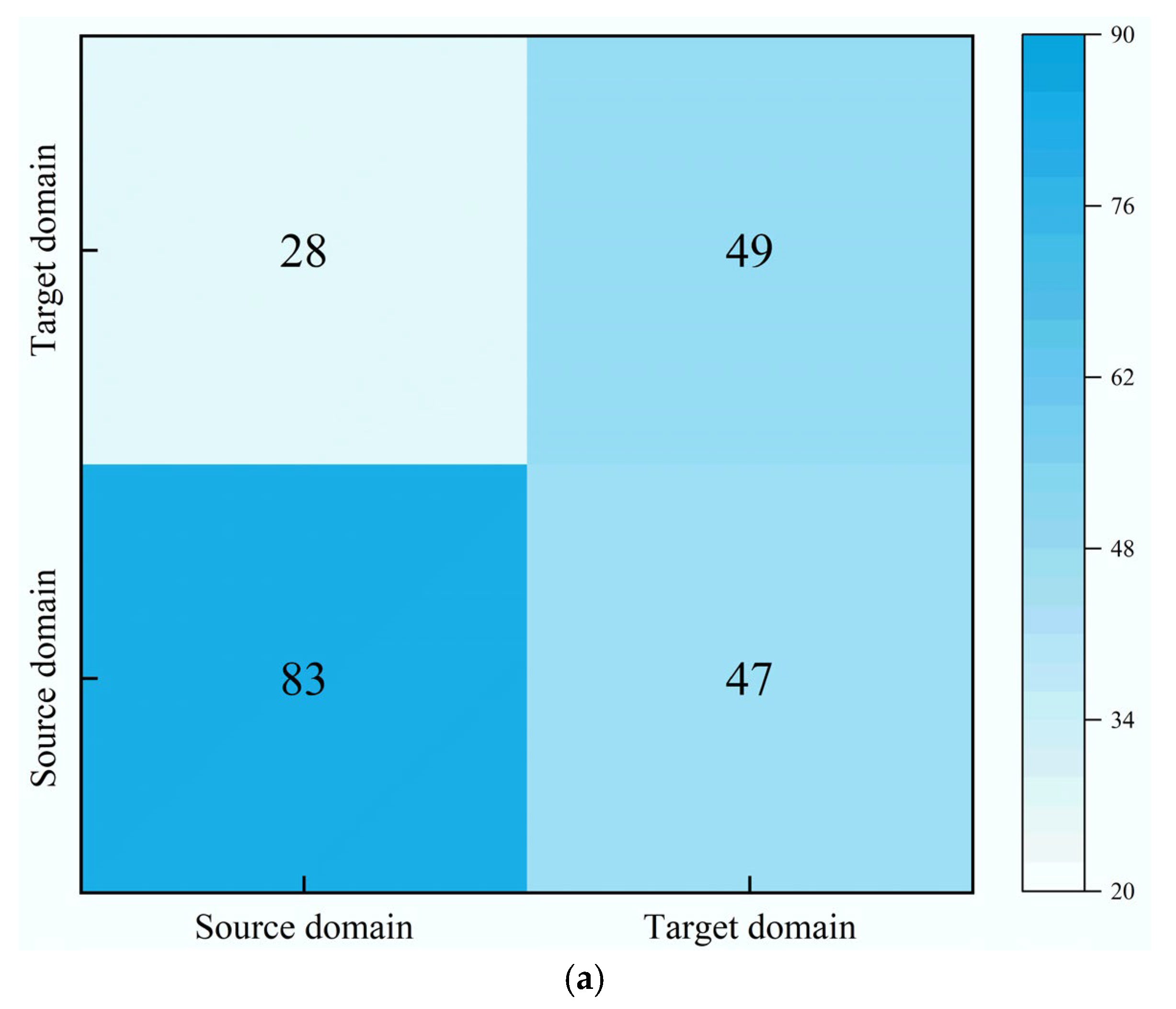
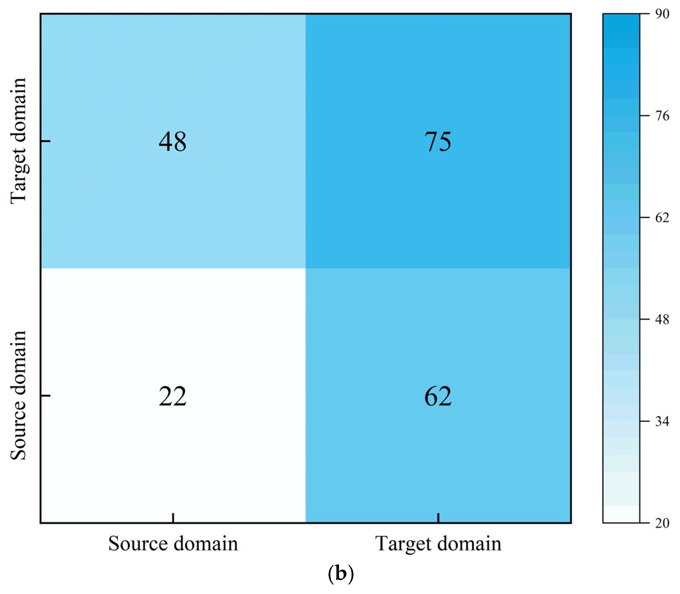
3.3.2. Results of Model Domain Classification

In the PIDANN model’s adversarial training process, the parameters of the feature extractor are updated to confuse the domain discriminator, thereby weakening its ability to correctly classify domain-specific information. This encourages the feature extractor to learn domain-invariant representations, facilitating transfer learning. As shown in Figure 7, the domain classification accuracy drops from 63.77% to 46.86%, indicating a significant reduction in the discriminator’s ability to distinguish between construction sections. This decline reflects effective alignment of feature distributions across domains, which is a desired outcome in domain adversarial learning. The resulting feature confusion provides a necessary basis for enabling the model to generalize across different construction sections or even distinct pipe jacking projects.
Figure 7. Confusion matrix of domain discriminator performance before and after adversarial learning: (a) before adversarial learning and (b) after adversarial learning.
Buildings 15 01337 g007aBuildings 15 01337 g007b

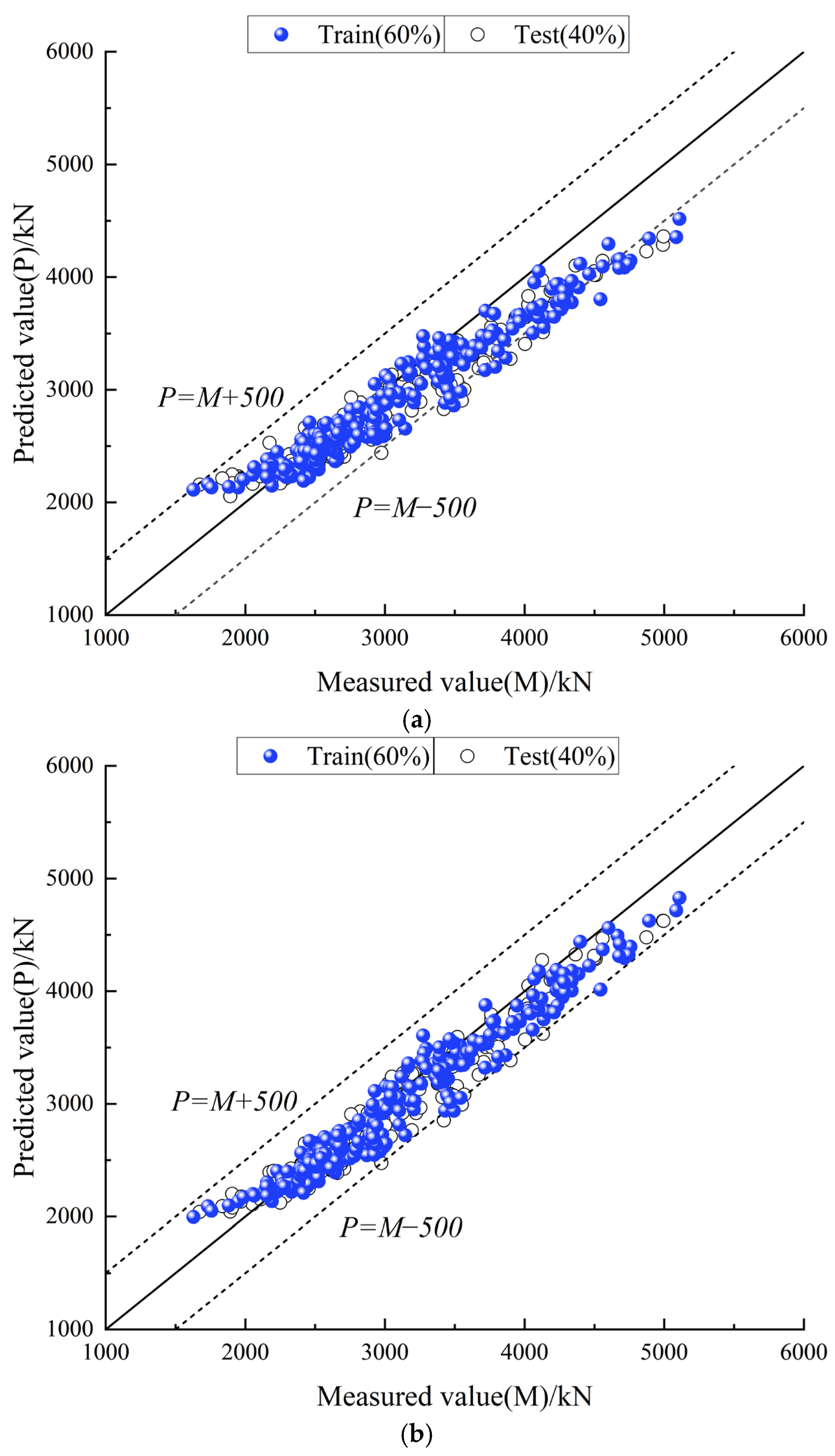
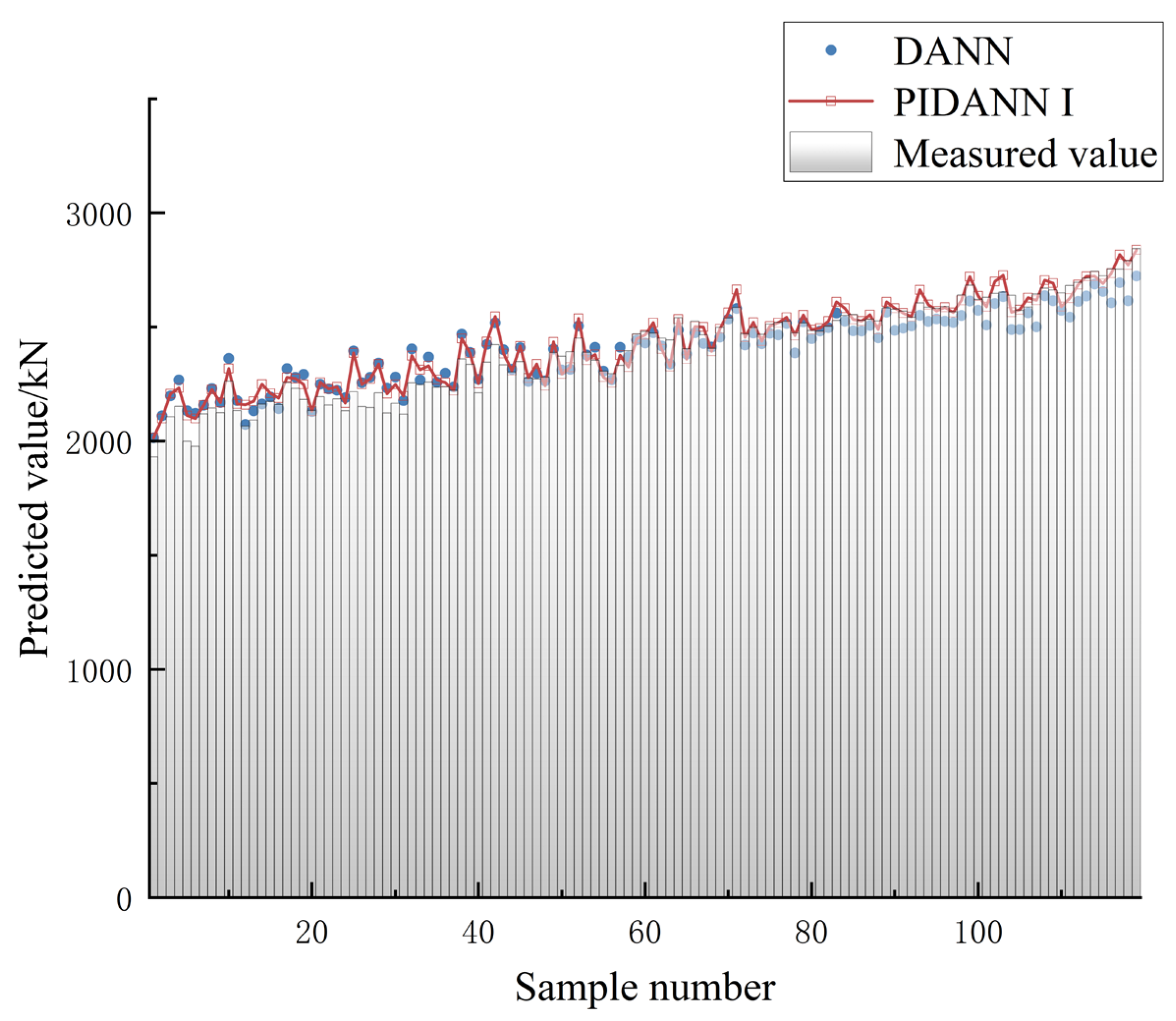
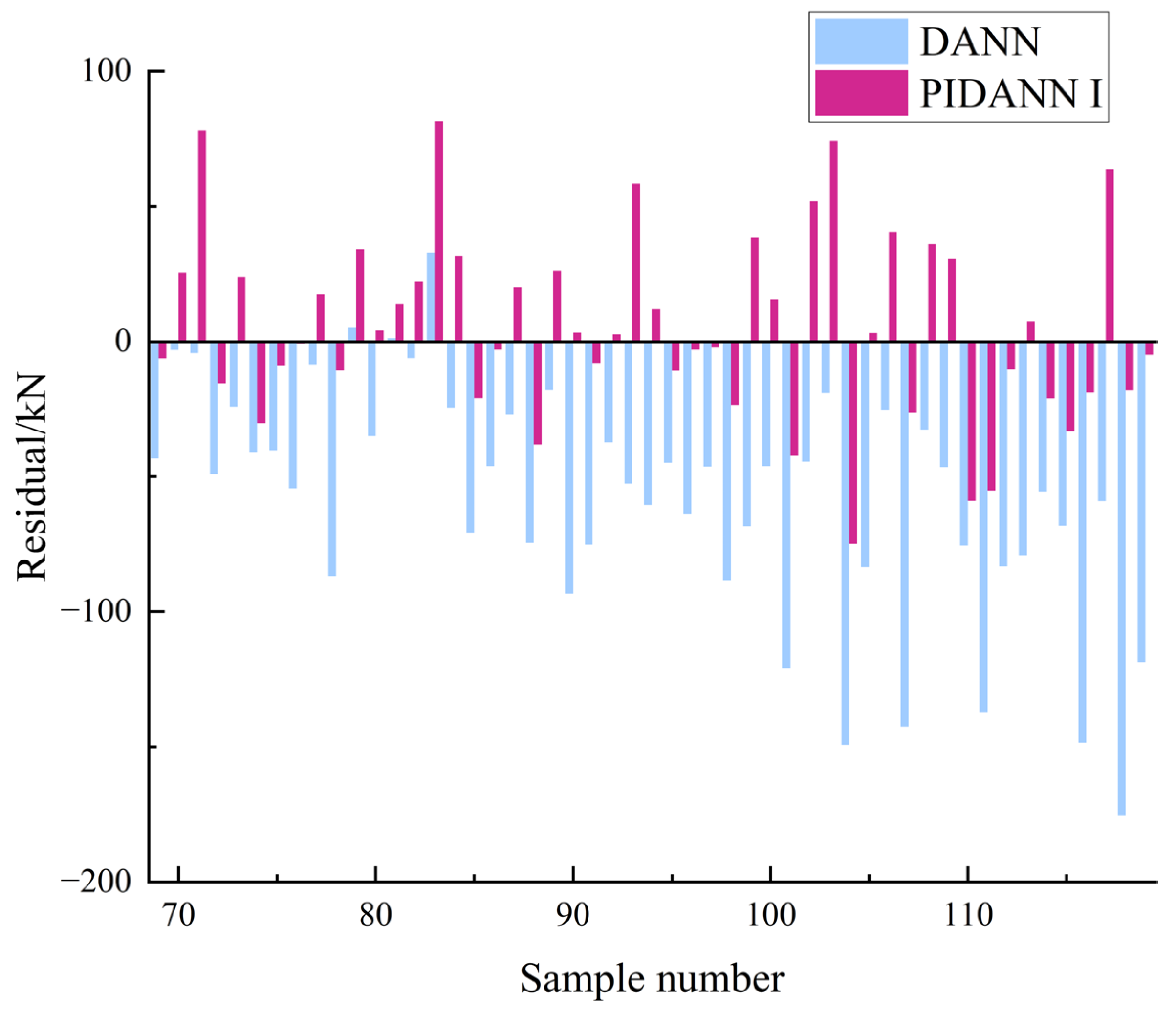
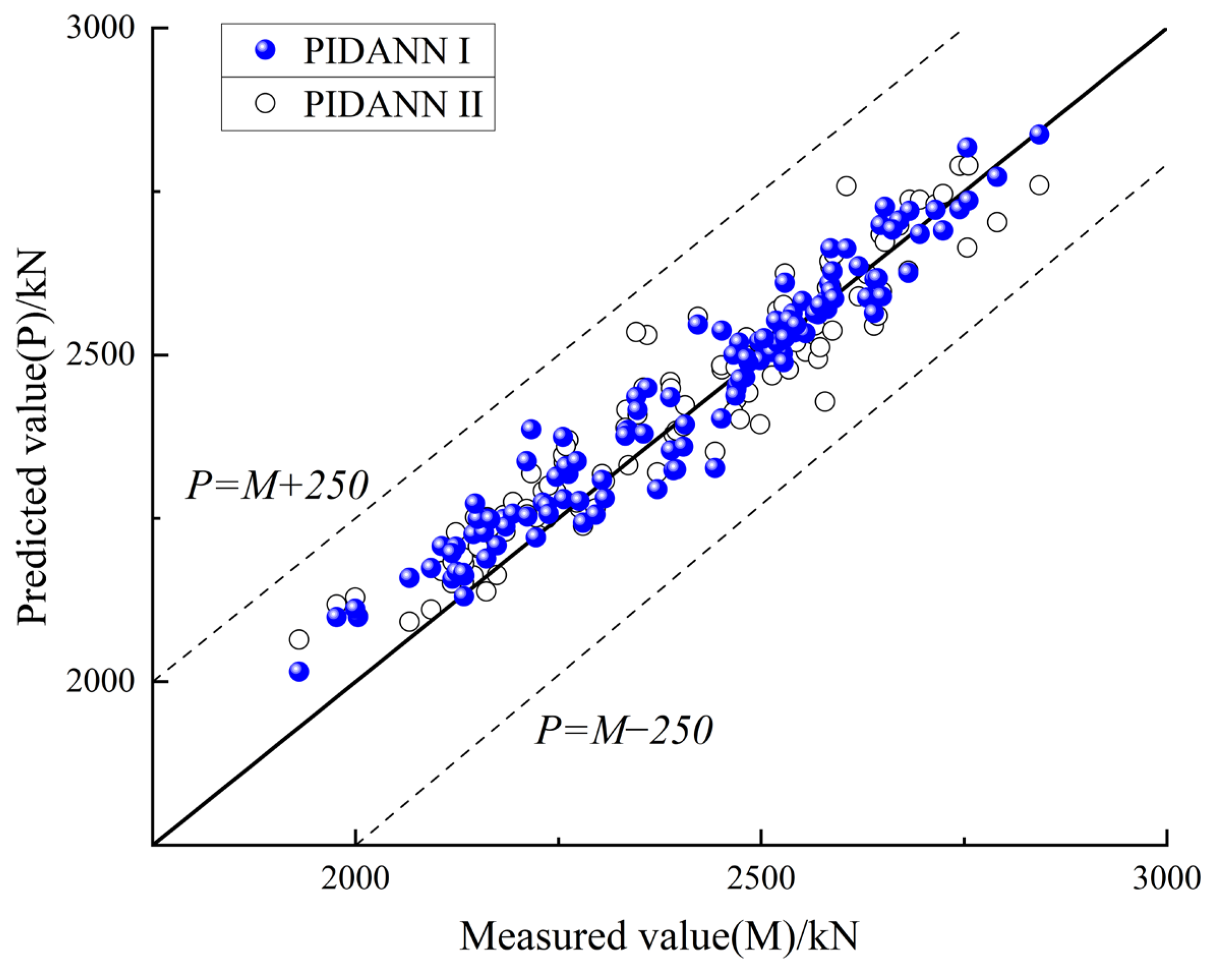
3.3.3. Analysis of the Effectiveness of Physical Information Integration

As shown in Table 4, the PIDANN model demonstrates improved prediction accuracy in both the training and test sets after incorporating physical constraints and physical-valued features. However, the RMSE of the test set increases slightly from 182.49 to 190.17, and the MAE increases from 139.71 to 147.34 compared to the training set. In contrast, when physical constraints and physically valued features are added, the increases in RMSE and MAE on the test set are relatively smaller. This suggests that incorporating physical constraints and physically valued features can enhance the generalization ability of the model to some extent, as reflected by the reduced growth in error evaluation metrics RMSE and MAE.
Table 4. Comparison of evaluation metrics of prediction results of training set and test set.
ModelDatasetMSE (kN2)RMSE (kN)MAE (kN)MAPE (%)R2
DANNTrain33,302.20 182.49 139.71 4.43 0.94
Test36,164.64 190.17 147.34 4.93 0.92
PIDANN ITrain32,200.40 179.44 139.23 4.51 0.94
Test32,446.62 180.13 141.65 4.86 0.93
PIDANN IITrain30,623.68 175.00 135.52 4.34 0.94
Test32,755.01 180.98 139.87 4.72 0.93
The logged data from Working Shaft No. 3, which was not involved in the model training process, was selected as a new test set to further evaluate the generalization ability of the model. Figure 8 presents the model’s prediction results on the test set from Shaft No. 3. As shown in Figure 8, the model with added physical constraints demonstrates better fitting performance on the new test set. Notably, from Sample No. 69 onward, the DANN model without physical constraints exhibits lower prediction values. Figure 9 further illustrates that the DANN model without physical constraints generally shows larger negative residuals in the latter half of the section.
Figure 8. Prediction performance of the PIDANN model on Working Shaft No. 3.
Buildings 15 01337 g008
Figure 9. Residual analysis of PIDANN predictions for Working Shaft No. 3.
Buildings 15 01337 g009
As summarized in Table 1, the theoretical jacking force model provides a conservative estimation of frictional resistance within a reasonable range. In contrast, the model incorporating physical constraints generates predictions that better align with the physical information on the test set of Shaft No. 3 without producing significant negative residuals. The inclusion of physical constraints enables the model to optimize predictions toward theoretical values through the back-propagation mechanism. This allows the model to produce results that approximate both the training data and the theoretical values, enhancing its prediction accuracy. On the other hand, purely data-driven models tend to be overly dependent on the training data, which limits their adaptability. This observation is reflected in the error metrics, which show that the prediction model with physical constraints achieves lower prediction errors across different construction sections. This suggests that incorporating physical constraints improves the model’s adaptability by enhancing its ability to generalize across varying construction conditions.
As shown in Figure 10, the PIDANN I model outperforms the standard DANN and PIDANN II models, exhibiting significantly lower prediction errors on the new test set. While PIDANN II improves accuracy by enriching feature information with theoretical values, its reliance on training data limits generalization compared to the physically constrained approach. Figure 11 further confirms that both PIDANN models align well with the reference line P = M, with PIDANN I achieving a better fit, indicating superior predictive performance.
Figure 10. Evaluation metrics of different models on Working Shaft No. 3.
Buildings 15 01337 g010
Figure 11. Performance comparison of various models on Working Shaft No. 3 dataset.
Buildings 15 01337 g011

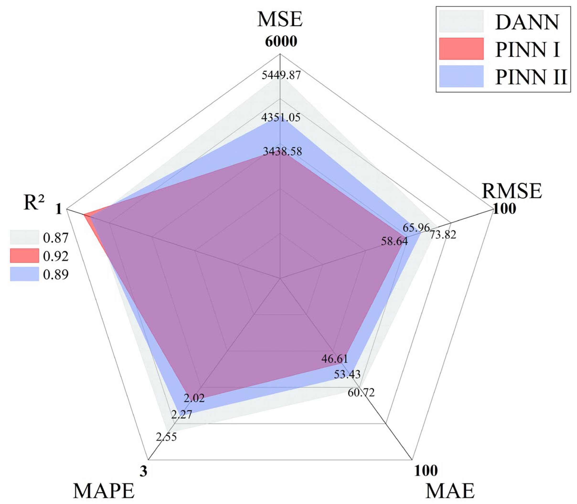
3.3.4. Comparison of Non-Transfer Learning Models and DANN Models

To further validate the jacking force prediction performance of the DANN model, a comparison is conducted with non-transfer learning models that do not integrate information, including the Convolutional Neural Network (CNN) [37], Long Short-Term Memory Network (LSTM) [38], Back-Propagation Neural Network (BP) [15,17], Support Vector Regression (SVR) [17], and Random Forest (RF) [39]. The training and test sets for all models utilize the same datasets from Working Shaft No. 1 and Working Shaft No. 2, while the dataset from Working Shaft No. 3 is used as an additional test set to evaluate the generalization performance of the models. The results based on prediction metrics for the Working Shaft No. 3 dataset are presented in Table 5.
Table 5. Evaluation metrics comparison of prediction results between non-transfer learning model and DANN model.
ModelMSE (kN2)RMSE (kN)MAE (kN)MAPE (%)R2
CNN27,516.61 165.88 134.92 5.57 0.35
LSTM21,099.63 145.25 115.94 4.85 0.50
BP26,504.26 162.80 134.37 5.69 0.38
SVR17,180.08 131.07 108.26 4.48 0.60
RF26,777.62 163.63 136.33 5.72 0.37
DANN5449.87 73.82 60.72 2.55 0.87
PINN I4351.05 65.96 53.43 2.27 0.90
PINN II3438.58 58.64 46.61 2.02 0.92
As shown in Table 5, the coefficient of determination (R2) of the PIDANN I model exceeds those of the non-transfer learning models by 0.55, 0.40, 0.52, 0.30, and 0.53, respectively. In terms of error metrics, the RMSE of the PIDANN I model is reduced by 99.92 kN, 79.29 kN, 96.84 kN, 65.11 kN, and 97.67 kN compared to the non-transfer learning models. This demonstrates that the transfer learning approach effectively facilitates knowledge transfer across multi-source data, thereby significantly improving prediction accuracy. Moreover, the integration of physical information further enhances the predictive performance of the DANN model, successfully achieving a complementary fusion of physical modeling and data-driven learning.

4. Discussion

While the proposed theoretical model provides a physically grounded foundation for jacking force prediction, it is built upon certain simplifications to ensure analytical tractability. For instance, the pipe–soil contact pressure is estimated using the Persson contact model under a simplified contact angle assumption, and the effect of slurry lubrication is treated as uniform along the pipe–soil interface. These assumptions may not fully capture the complex interactions that occur in heterogeneous soil conditions or under non-uniform construction practices. Acknowledging these limitations is crucial, especially for extending the model to projects with highly variable stratigraphy or inconsistent slurry injection. Despite these simplifications, the model serves as an effective representation of the dominant physical mechanisms in many practical scenarios and offers valuable input for guiding the development of the PIDANN framework.
The results confirm that the proposed PIDANN model significantly improves the prediction accuracy and generalization performance compared to conventional data-driven models. By integrating theoretical constraints and expanding input features with physical values, the model achieves substantial reductions in MSE—36.9% and 20.2% on the new test set—demonstrating the effectiveness of domain knowledge in enhancing learning outcomes. The PIDANN model outperforms traditional approaches such as CNN, LSTM, and standard DANN, particularly under varying construction conditions. Its domain adaptation mechanism enables robust feature alignment, allowing the model to maintain performance across different work sites. Moreover, introducing theoretical values improves model stability and mitigates overfitting, especially in data-scarce scenarios. While adversarial training enhances transferability, performance may still be affected when domain discrepancies are large. Future studies could refine this process using adaptive weighting or advanced adaptation strategies to address highly heterogeneous datasets.
Overall, the PIDANN model demonstrates significant improvements in jacking force prediction accuracy and generalization ability. The findings reinforce the value of integrating physical principles with deep learning to enhance predictive performance in engineering applications. These insights contribute to the ongoing development of hybrid modeling approaches that leverage both physics-based knowledge and data-driven learning for more reliable and interpretable predictions in geotechnical and construction engineering. In practical applications, the PIDANN model can be deployed by connecting on-site sensors to an external computing device. Real-time construction data—such as jacking speed, advance distance, and mud pressure—can be continuously collected and input into the model. This enables the dynamic prediction of jacking force at specified time or distance intervals, allowing the model to respond promptly to changes in geological conditions or construction parameters. These predictions can then assist the hydraulic jack control system, providing data-driven guidance for adjusting jacking strategies in real time.

5. Conclusions

The study proposes a theoretical jacking force calculation model based on the partial contact assumption of the pipe–soil interface, incorporating the pressure arch effect and drag reduction measures. The Persson contact model and the parallel plate fluid power law model are utilized to compute the drag force. To improve prediction accuracy, the PIDANN model is introduced, integrating physics information and DANN. A comparative analysis with various baseline models was conducted, and the key findings are summarized as follows:
(1)
The proposed jacking force calculation model improves prediction accuracy, particularly for long-distance pipe jacking, significantly reducing cumulative error.
(2)
Adversarial training enhances predictive performance, with the DANN framework effectively capturing domain shifts in different construction sections.
(3)
The PIDANN model outperforms the purely data-driven DANN model, achieving 36.9% and 20.2% lower mean squared error (MSE) on the new test set, indicating reduced overfitting and improved generalization.
(4)
PIDANN successfully transfers knowledge across different data sources, leading to superior prediction accuracy compared to non-transfer learning machine learning methods.
Due to the complexity of the pipe jacking construction process, the physical-data dual-driven PIDANN model requires further refinement. Specifically, the representation of physical mechanisms within the model and the seamless integration of the physical and data-driven components warrant further investigation. Additionally, the engineering data used in this study is limited. Consequently, it will be a focus of future research to enable data sharing and develop an “Engineering AI Large Model” with diverse functional capabilities to guide construction in similar projects.

Author Contributions

Y.Y.: conceptualization, formal analysis, investigation, methodology, funding acquisition, writing—review and editing. Y.L.: formal analysis, software, writing—original draft preparation, visualization. J.Z.: methodology, project administration, validation. Z.Z.: visualization, investigation. Q.L.: funding acquisition, data curation, resources. All authors have read and agreed to the published version of the manuscript.

Funding

This study was supported by the Science and Technology Research Project of the Henan Provincial Water Conservancy Department (GG202358—Research and Application of Key Technologies for Long-Distance Large-Diameter Pipe Jacking Construction in Complex Geological Conditions).

Data Availability Statement

The original contributions presented in the study are included in the article, further inquiries can be directed to the corresponding authors.

Conflicts of Interest

Author Qunsheng Li was employed by the company Henan Water Conservancy Engineering First Group Co., Ltd. The remaining authors declare that the research was conducted in the absence of any commercial or financial relationships that could be construed as a potential conflict of interest.

References

  1. Zhang, B.; Liu, J. Study on safety of existing rail transit tunnel undercrossing with pipe jacking method. J. Saf. Sci. Technol. 2023, 19, 162–167. [Google Scholar] [CrossRef]
  2. Hong, K. Development and Prospects of Tunnels and Underground Works in China in Recent Two Years. Tunn. Constr. 2017, 37, 123–134. [Google Scholar] [CrossRef]
  3. Li, P.; Dai, Z.; Huang, D.; Cai, W.; Fang, T. Impact Analysis for Safety Prevention and Control of Special-Shaped Shield Construction Closely Crossing Multiple Operational Metro Tunnels in Shallow Overburden. Geotech. Geol. Eng. 2022, 40, 2127–2144. [Google Scholar] [CrossRef]
  4. Haslem, R. Pipe jacking forces: From theory to practice. In Proceedings of ICE North Western Association Centenary Conference in Infrastructure Renovation and Waste Control, Manchester, UK, 8–10 April 1986; pp. 173–180. [Google Scholar]
  5. Oreilly, M.; Rogers, D. Pipe jacking forces. In Proceedings of the International Conference on Foundations and Tunnels, London, UK, 24–26 March 1987; pp. 201–208. [Google Scholar]
  6. Bennett, R.D. Jacking Loads and Ground Deformations Associated with Microtunneling; University of Illinois at Urbana-Champaign: Champaign, IL, USA, 1998. [Google Scholar]
  7. GB 50268-2008; Specification for Construction and Acceptance of Water Supply and Drainage Pipeline Projects. Beijing Municipal Construction Group Co., Ltd.: Beijing, China, 2008; 255P, p. A255.
  8. Milligan, G.W.E.; Norris, P. Pipe–soil interaction during pipe jacking. Geotech. Eng. 1999, 137, 27–44. [Google Scholar] [CrossRef]
  9. Saeid, K.; Hideki, S.; Kikuo, M. Analysis and prediction of thrust in using slurry pipe jacking method Tunn. Undergr. Space Technol. Inc. Trenchless Technol. Res. 2004, 19, 356. [Google Scholar]
  10. Ji, Q.; Zixuan, Z.; Xiaohui, W.; Mengjie, S.; Tianjiao, P. Research on Interpretable Methods of Machine Learning Applied in Intelligent Analysis of Power System (Part II): Physics-embedded Machine Learning for Power System Stability Analysis. Proc. CSEE 2023, 43, 9046–9059. [Google Scholar] [CrossRef]
  11. Peerun, M.I.; Ong, D.E.L.; Desha, C. A strategic review on enhanced DEM simulation and advanced 3-D particle printing techniques to improve pipe-jacking force prediction. Tunn. Undergr. Space Technol. Inc. Trenchless Technol. Res. 2022, 123, 104415. [Google Scholar] [CrossRef]
  12. Zhang, W.; Li, H.; Li, Y.; Liu, H.; Chen, Y.; Ding, X. Application of deep learning algorithms in geotechnical engineering: A short critical review. Artif. Intell. Rev. 2021, 54, 5633–5673. [Google Scholar] [CrossRef]
  13. Wang, L.; Yi, S.; Yu, Y.; Gao, C.; Samali, B. Automated ultrasonic-based diagnosis of concrete compressive damage amidst temperature variations utilizing deep learning. Mech. Syst. Signal Process. 2024, 221, 111719. [Google Scholar] [CrossRef]
  14. Yu, Y.; Zhang, C.; Xie, X.; Yousefi, A.M.; Zhang, G.; Li, J.; Samali, B. Compressive strength evaluation of cement-based materials in sulphate environment using optimized deep learning technology. Dev. Built Environ. 2023, 16, 100298. [Google Scholar] [CrossRef]
  15. Han, Y.; Wang, Y.; Liu, C.; Hu, X.; Du, L. Application of regularized ELM optimized by sine algorithm in prediction of ground settlement around foundation pit. Environ. Earth Sci. 2022, 81, 413. [Google Scholar] [CrossRef]
  16. Hu, D.; Hu, Y.; Yi, S.; Liang, X.; Li, Y.; Yang, X. Surface Settlement Prediction of Rectangular Pipe-Jacking Tunnel Based on the Machine-Learning Algorithm. J. Pipeline Syst. Eng. Pract. 2024, 15, 04023061. [Google Scholar] [CrossRef]
  17. Zhou, H.; Huang, S.; Zhang, P.; Ma, B.; Ma, P.; Feng, X. Prediction of jacking force using PSO-BPNN and PSO-SVR algorithm in curved pipe roof. Tunn. Undergr. Space Technol. 2023, 138, 105159. [Google Scholar] [CrossRef]
  18. Dai, Z.; Li, P.; Liu, J.; Liu, X.; Rui, Y.; Zhai, Y. Data-driven prediction for curved pipe jacking performance during underwater excavation of ancient shipwreck using an attention-based graph convolutional network approach. Expert Syst. Appl. 2024, 236, 121393. [Google Scholar] [CrossRef]
  19. Liu, Y.; Hou, S.; Cheng, L.; Huang, Y. Advances and key technologies of intelligent construction of hydraulic engineering. Water Resour. Hydropower Eng. 2022, 53, 1–20. [Google Scholar] [CrossRef]
  20. Ganin, Y.; Ustinova, E.; Ajakan, H.; Germain, P.; Larochelle, H.; Laviolette, F.; March, M.; Lempitsky, V. Domain-adversarial training of neural networks. J. Mach. Learn. Res. 2016, 17, 1–35. [Google Scholar]
  21. Farbiz, F.; Habibullah, M.S.; Hamadicharef, B.; Maszczyk, T.; Aggarwal, S. Knowledge-embedded machine learning and its applications in smart manufacturing. J. Intell. Manuf. 2023, 34, 2889–2906. [Google Scholar] [CrossRef]
  22. Rueden, L.V.; Mayer, S.; Beckh, K.; Georgiev, B.; Giesselbach, S.; Heese, R.; Kirsch, B.; Pfrommer, J.; Pick, A.; Ramamurthy, R.; et al. Informed Machine Learning—A Taxonomy and Survey of Integrating Prior Knowledge into Learning Systems. IEEE Trans. Knowl. Data Eng. 2023, 35, 614–633. [Google Scholar] [CrossRef]
  23. Oz, B.; Karalar, M. A Consensus-Based Likert–LMBP Model for Evaluating the Earthquake Resistance of Existing Buildings. Appl. Sci. 2024, 14, 6492. [Google Scholar] [CrossRef]
  24. Raissi, M.; Perdikaris, P.; Karniadakis, G.E. Physics-informed neural networks: A deep learning framework for solving forward and inverse problems involving nonlinear partial differential equations. J. Comput. Phys. 2019, 378, 686–707. [Google Scholar] [CrossRef]
  25. Yu, B.; Gan, Z.; Zhang, S.; Gu, Y.; Yao, W. Prediction of 2D/3D unsteady-state tempertayure fieldsamd heat sources upon the physics-informed neural networks. Eng. Mech. 2023, 1–13. [Google Scholar] [CrossRef]
  26. Xu, J.; Zhu, H.; Zhu, J.; Li, C. Solution approach of Burgers-Fisher equation based onphysics-informed neural networks. J. Zhejiang Univ. Eng. Sci. 2023, 57, 2160–2169. [Google Scholar] [CrossRef]
  27. Chen, Z.; Lai, S.-K.; Yang, Z. AT-PINN: Advanced time-marching physics-informed neural network for structural vibration analysis. Thin-Walled Struct. 2024, 196, 111423. [Google Scholar] [CrossRef]
  28. Liao, W.; Long, X.; Jiang, C. A physics-informed neural network method for identifying parameters and predicting remaining life of fatigue crack growth. Int. J. Fatigue 2025, 191, 108678. [Google Scholar] [CrossRef]
  29. Wang, J.; Zhang, D.; Chen, J.; Fang, Q.; Sun, Z.; Lu, S. A novel mechanics model for predicting vertical load and jacking force via rectangle pipe considering soil arching effect. Tunn. Undergr. Space Technol. 2024, 152, 105952. [Google Scholar] [CrossRef]
  30. Lin, X.-T.; Chen, R.-P.; Wu, H.-N.; Meng, F.-Y.; Su, D.; Han, K. Calculation of earth pressure distribution on the deep circular tunnel considering stress-transfer mechanisms in different zones. Tunn. Undergr. Space Technol. 2022, 119, 104211. [Google Scholar] [CrossRef]
  31. Hou, J.; Xiao, C.; Li, j.; Zhi, B.; Li, J. A mechanical model of the pipe section construction process considering the Interaction of pipe-soil-slurry. Chin. J. Undergr. Space Eng. 2023, 19, 767–776. [Google Scholar]
  32. Ciavarella, M.; Decuzzi, P. The state of stress induced by the plane frictionless cylindrical contact. I. The case of elastic similarity. Int. J. Solids Struct. 2001, 38, 4507–4523. [Google Scholar] [CrossRef]
  33. Ye, Y.; Peng, L.; Zhou, Y.; Yang, W.; Shi, C.; Lin, Y. Prediction of Friction Resistance for Slurry Pipe Jacking. Appl. Sci. 2020, 10, 207. [Google Scholar] [CrossRef]
  34. Zhang, P.; Tan, L.; Ma, B. Formulae for frictional resistance considering mud thixotropy and pipe-soil contact characteristics. Chin. J. Geotech. Eng. 2017, 39, 2043–2049. [Google Scholar] [CrossRef]
  35. Zhang, P.; Ma, B.; Zeng, C.; Tan, L. Numerical model for jacking force based on pipe-soil contact characteristies. Chin. J. Geotech. Eng. 2017, 39, 244–249. [Google Scholar] [CrossRef]
  36. Wang, S.; Xia, C.; Ge, J. Formulae oflateral friction resistance for pipe-jackingconsidering different forms of mud screen. Rock Soil Mech. 2014, 35, 159–166+174. [Google Scholar] [CrossRef]
  37. Zhu, H.; Jia, Z.; Li, Q. CNN-based fault location of distributionnetwork. Water Resour. Power 2021, 39, 188–191. [Google Scholar]
  38. Wang, X.; Li, K.; Zhang, Z.; Yu, H.; Kong, L.; Chen, W. Coupled ALO-LSTM and feature attention mechanism prediction model for seepage pressure of earth-rock dam. J. Hydraul. Eng. 2022, 53, 403–412. [Google Scholar] [CrossRef]
  39. Zhang, S.; Shu, H.; Liu, X.; Huang, S.; Zhou, H. Investigating on intelligent classification of surrounding rock for horizontal directional bore hole based on machine learning. Yangtze River 2023, 54, 156–165. [Google Scholar] [CrossRef]
Disclaimer/Publisher’s Note: The statements, opinions and data contained in all publications are solely those of the individual author(s) and contributor(s) and not of MDPI and/or the editor(s). MDPI and/or the editor(s) disclaim responsibility for any injury to people or property resulting from any ideas, methods, instructions or products referred to in the content.

