1. Introduction
The sheet pile wall, which evolved from anti-sliding piles, is a widely used retaining structure in railway engineering. By placing sheeting plates between adjacent anti-sliding piles, the interaction between the piles, panels, and soil helps maintain the stability and bearing capacity of the structure, effectively preventing issues such as soil collapse and water seepage [
1]. Stewart et al. [
2] systematically summarized the design methods for sheet pile walls based on the stress characteristics and displacement variations observed in engineering practice, including displacement methods, pressure methods, and finite element methods. Madabhushi and Chandrasekaran [
3] proposed an axis–point positioning method based on the minimal moment ratio, which demonstrated good applicability in both cohesive and non-cohesive soils. Huang Zhiyun et al. [
4] conducted in-depth research on the soil arch effect and earth pressure transfer characteristics of sheet pile walls through field monitoring and model tests, finding significant time effects on the earth pressure at the back of the piles and the center of the panel between piles. Additionally, they discovered that the stiffness, spacing, arrangement, and soil properties of the panels significantly influenced the soil arch effect. However, traditional sheet pile walls still face technical bottlenecks such as limited treatment height, excessive structural size, high construction difficulty, and difficulty in controlling top displacement, particularly under poor foundation conditions, where construction costs significantly increase [
5].
Geosynthetic-reinforced soil technology is an economical and efficient soil reinforcement method [
6,
7,
8,
9]. By adding reinforcement materials into embankment soils, the soil gains a certain degree of “tensile strength”. However, this technology still faces shortcomings in soil strength and stiffness. Therefore, it is crucial to develop a new construction or structural model to improve load–displacement characteristics [
10]. Geosynthetic-reinforced soil technology is a passive soil reinforcement technique that requires the soil to undergo some deformation to trigger the interaction between the reinforcement and the soil. The stress induced by soil compaction or preloading can be regarded as a form of “prestress” [
11]. This stress effectively activates the reinforcement–soil interaction, improving the stiffness, strength, and overall stability of the geosynthetic-reinforced soil structure [
12,
13,
14]. Tatsuoka et al. [
15] confirmed, through plane strain compression tests, that applying a preload significantly improved the drained strength of reinforced saturated soft clay. Shinoda et al. [
16] developed a ratchet connection system, which effectively improved the stability of preloaded and prestressed (PLPS) geosynthetic-reinforced soil structures under seismic action. This system ensured that the backfill soil maintained a high prestress state during shrinkage, preventing backfill expansion and effectively suppressing shear and bending deformations under seismic loads. Ma Shuwen et al. [
17] proposed a prestressed reinforced embankment to address rockfall impact problems in mountainous embankments and designed a model test to explore its deformation characteristics and mechanical response. The results showed that the structure could significantly reduce the embankment settlement deformation caused by impacts. However, the mechanism and effects of this “prestress” measure in railway sheet pile wall retaining embankments still require further investigation.
Based on the above research background, this paper proposes a “prestressed” geosynthetic-reinforced sheet pile retaining wall structure. This structure introduces “prestress” into traditional geosynthetic-reinforced soil technology to strengthen the interaction between the reinforcement and soil. The goal is to improve the bearing capacity and stability of the structure, control horizontal displacement of the sheet pile wall, and ensure the safe operation of railway lines. Through indoor model tests, this study applies preloading to the fill material and reinforcement to generate “prestress” and systematically investigates the bearing and deformation characteristics of the “prestressed” geosynthetic-reinforced sheet pile retaining wall structure on sandy foundations.
2. Experimental Investigation
2.1. Similarity Theory
Scaled model tests were performed to investigate the bearing and deformation characteristics of the “prestressed” geosynthetic-reinforced sheet pile retaining wall structure. The first step was to determine the scale ratio for the indoor model tests, ensuring that the model and prototype satisfied geometric, physical, and phenomenological similarities. The key physical quantities involved in the tests included the model’s geometric dimensions (
l), soil density (
ρ), gravitational acceleration (
g), soil cohesion (
c), the soil’s internal friction angle (
φ), elastic modulus (
E), stress (
σ), strain (
ε), and displacement (
s). Based on the dimensional homogeneity principle, these physical quantities followed specific functional relationships:
Here, length (
L), mass (
M), and time (
T) were considered the fundamental dimensions, with other variables expressed in terms of these basic dimensions. Three independent dimensional quantities were selected to establish the similarity ratios: the geometric scale ratio between the indoor model and the prototype (
Cl = 25), the gravitational acceleration scale ratio (
Cg = 1), and the density similarity ratio (
Cρ = 1, since the same soil material is used for both the prototype and model). Using Buckingham’s π-theorem, the similarity ratios for the remaining physical quantities were derived, as shown in
Table 1.
2.2. Model Test Design
The design of the prototype and scale model tests for the “prestressed” geosynthetic-reinforced sheet pile retaining wall structure was based on industry standards [
18,
19,
20,
21,
22], engineering practice [
23,
24,
25], and existing research findings [
26,
27,
28,
29]. The prototype sheet pile had a square section with dimensions of 1.5 m × 1.5 m, and the center-to-center distance between the piles was 5.875 m. A cantilevered sheeting plate was placed behind the piles. Based on engineering experience, the ratio of the cantilever segment length to the anchorage segment length was set to 1:1.5. Therefore, the cantilever segment length was designed to be 6 m, while the anchorage segment was 9 m, making the total pile length 15 m. Following the “Code for Design of Railway Earth Structure” [
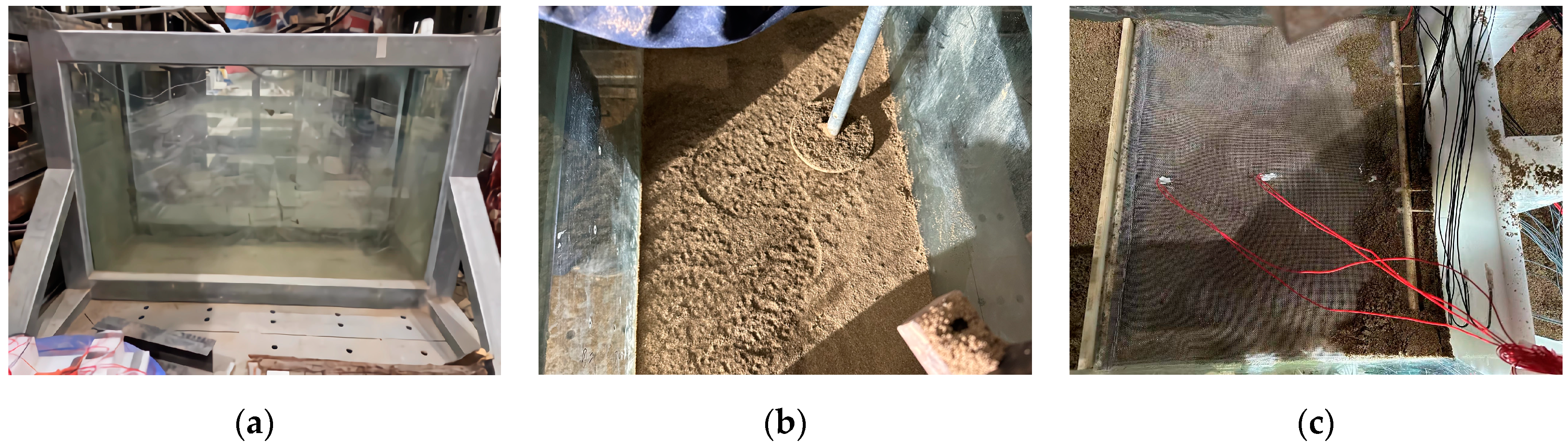
18], which specifies the subgrade surface requirements for high-speed railway single-track ballastless tracks, the subgrade width was set at 8.6 m with an embankment slope of 1:1.5. In this study, the prototype sheet pile wall consisted of five piles. To facilitate the observation of pile displacement, a half-structure model of the prototype was considered based on symmetry. The model test was arranged with two full piles and one-half pile. The process for preparing the “prestressed” geosynthetic-reinforced sheet pile retaining wall model is shown in
Figure 1:
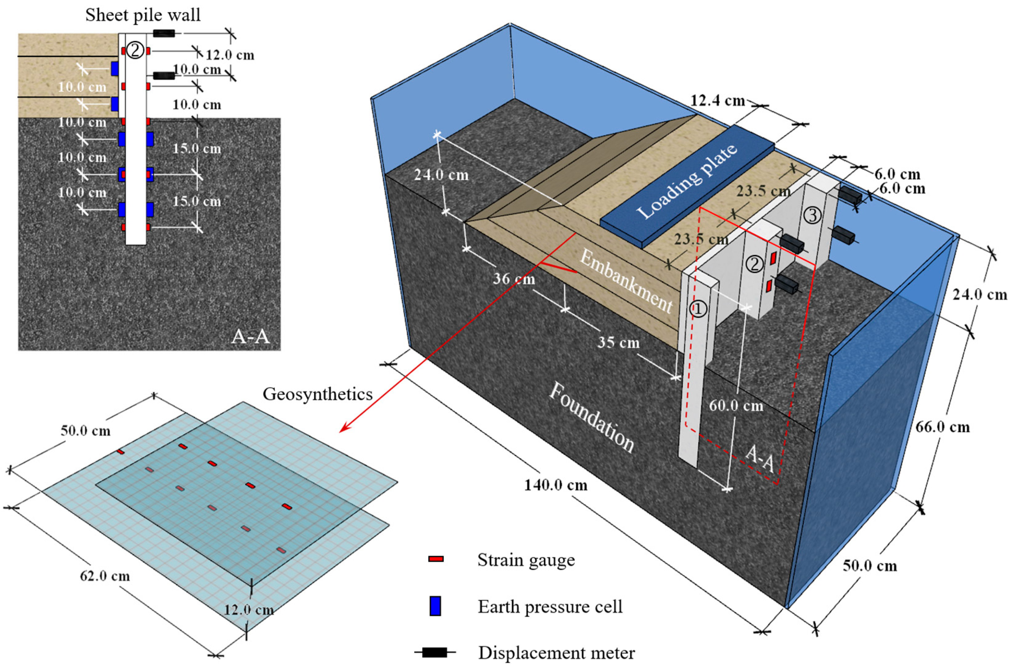
To study the bearing and deformation characteristics of the “prestressed” geosynthetic-reinforced sheet pile retaining wall, two scaled indoor model tests were designed, with pile spacings of 235 mm (Test 1) and 470 mm (Test 2). Taking Test 1 as an example, the main dimensions of the model and the sensor layout are shown in
Figure 2. Earth pressure cells were placed symmetrically on both sides of the central pile and behind the sheeting plate, with a 10 cm spacing along the burial depth. Strain gauges were attached to the pile body to measure the strain distribution and bending moment changes. Similarly, strain gauges on the reinforcement were spaced 10 cm apart. Since the central pile experienced less disturbance than the edge piles, displacement sensors were installed at both the top and midpoint of the cantilever segment of the central pile to monitor horizontal displacement. The displacement sensor had a range of 30 mm and an accuracy of 0.01 mm, which meets the test requirements.
The embankment was loaded by an actuator to apply uniform pressure through a 20 mm thick steel plate, which ensured sufficient stiffness. The prototype load distribution width was 3.1 m, corresponding to a model plate width of b = 124 mm. The test consisted of two phases: pre-prestressed and post-prestressed. The preloading process applied to the geosynthetic-reinforced soil was regarded as the pre-prestressed phase, which induced “prestress” to the geosynthetic-reinforced soil and also served as a basis for comparing the performance of geosynthetic-reinforced sheet pile retaining walls with and without “prestress”. The loading was displacement-controlled at a rate of 0.1 mm/min. The ultimate load for the “prestressed” geosynthetic-reinforced sheet pile retaining wall was defined as the point at which the loading plate displacement reached 0.1 b. Therefore, loading was stopped when the displacement of the loading plate reached 12.4 mm during both loading phases.
2.3. Experimental Materials and Parameters
2.3.1. Filling Materials
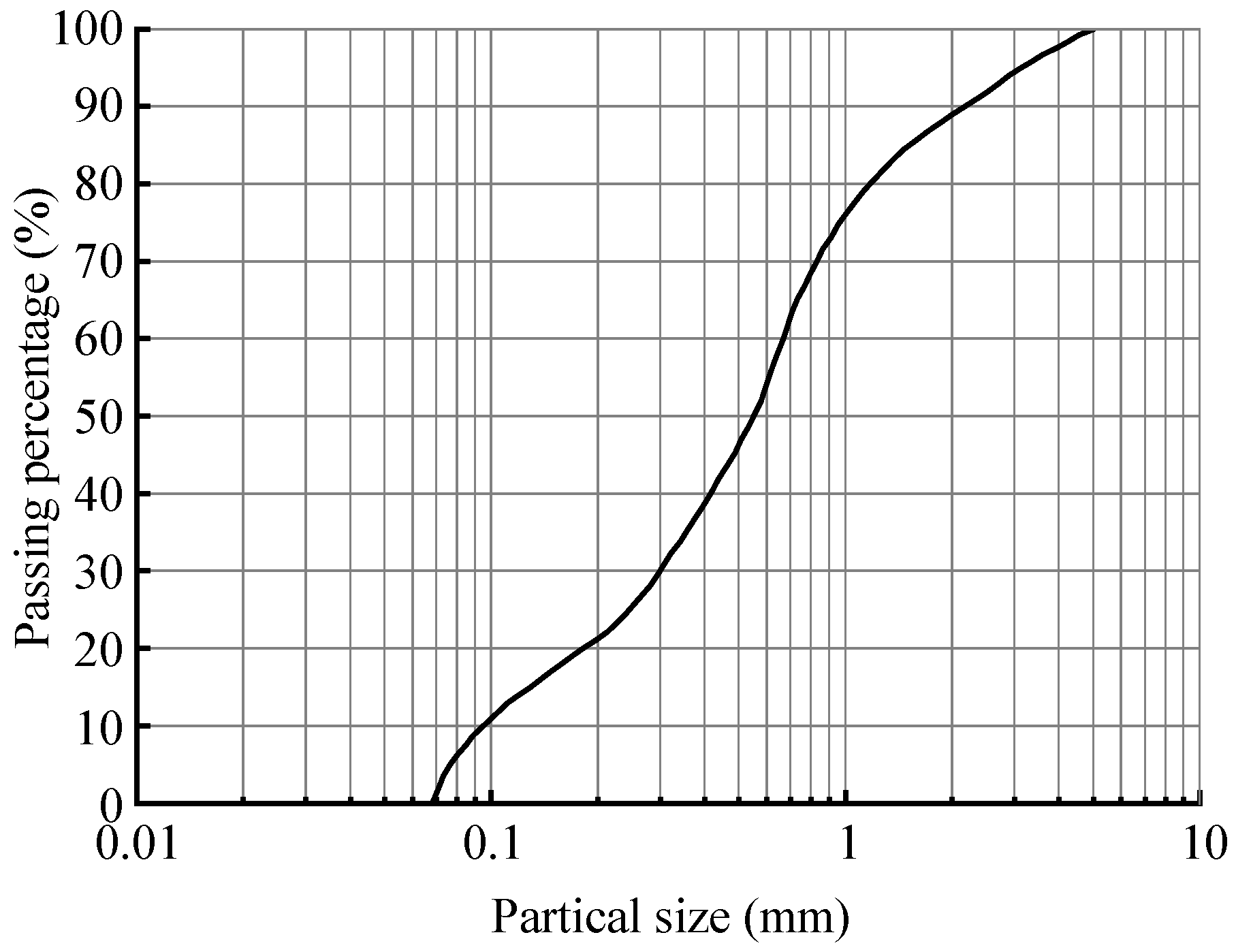
The embankment and foundation filling materials were sourced from local river sand. Sieving tests revealed that the particle size range of the river sand was 0.07 mm to 5 mm. The gradation curve of the sand is shown in
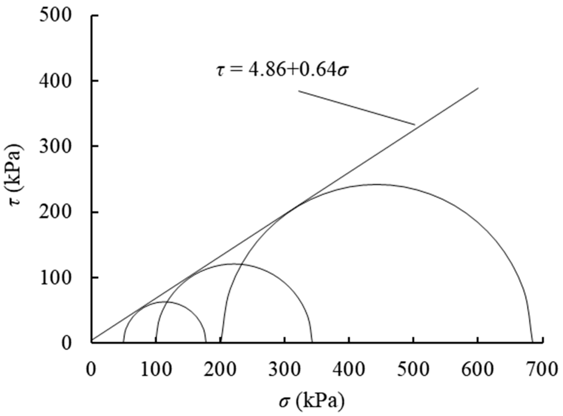
Figure 3. The particle sizes at which 60%, 30%, and 10% by mass are finer were 0.7 mm, 0.3 mm, and 0.09 mm, respectively. The coefficient of uniformity and curvature were 7.78 and 1.43, indicating that the material was well-graded soil. According to Louati H [
30], “capillary bridges” in unsaturated sandy soil particles can cause the sand to exhibit some degree of cohesion. Moreover, the river sand used in this study inevitably contained fine particles, which resulted in the observed apparent cohesion during the triaxial tests. The tests followed the “Code for soil test of railway engineering” [
31]. Confining pressures were set at 50 kPa, 100 kPa, and 200 kPa, with a shear strain rate of 0.8% per minute. The shear strength envelope for the soil samples is shown in
Figure 4. From the figure, the cohesion (c) of the river sand was determined to be 4.86 kPa, and the internal friction angle (
φ) was 32.6°.
2.3.2. Pile and Sheeting Plate Materials
According to similarity theory, the theoretical elastic modulus for the pile and panel model material was 1.2 GPa. In the experiment, polyethylene (PE) sheets were selected as the material for both the piles and sheeting plates. As shown in
Figure 5, the elastic modulus of PE was determined using a three-point bending test. Based on the measured mid-span deflection, the elastic modulus of PE plastic was calculated to be 1.32 GPa, satisfying the similarity conditions.
where
F is the concentrated load;
L is the calculated span;
ω is the mid-span vertical displacement, and
I is the sectional moment of inertia.
2.3.3. Geosynthetic Reinforcement Materials
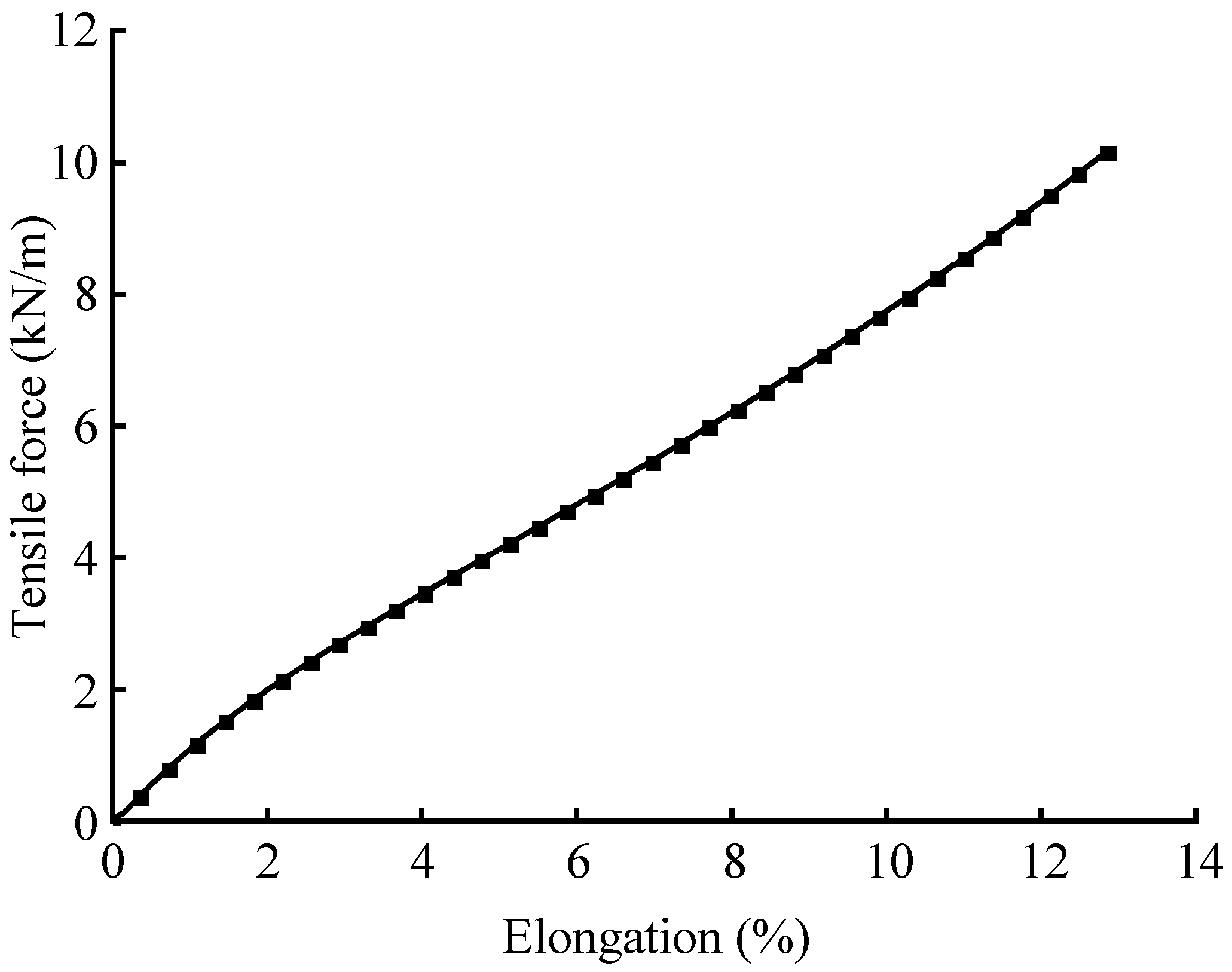
There is a significant difference in the tensile stiffness of various geosynthetic materials. In this experiment, a nylon mesh with relatively low tensile stiffness was selected as the reinforcement material, placed within the embankment fill. Tensile tests were conducted on a universal testing machine based on ASTM D4595-17 [
32]. The load–elongation curve for the nylon mesh is shown in
Figure 6. The nylon mesh exhibited a tensile strength of 10.16 kN/m, at which point the secant modulus was determined to be 79.19 kN/m, corresponding to a maximum elongation of 12.83%.
3. Results
3.1. Load–Settlement Relationship
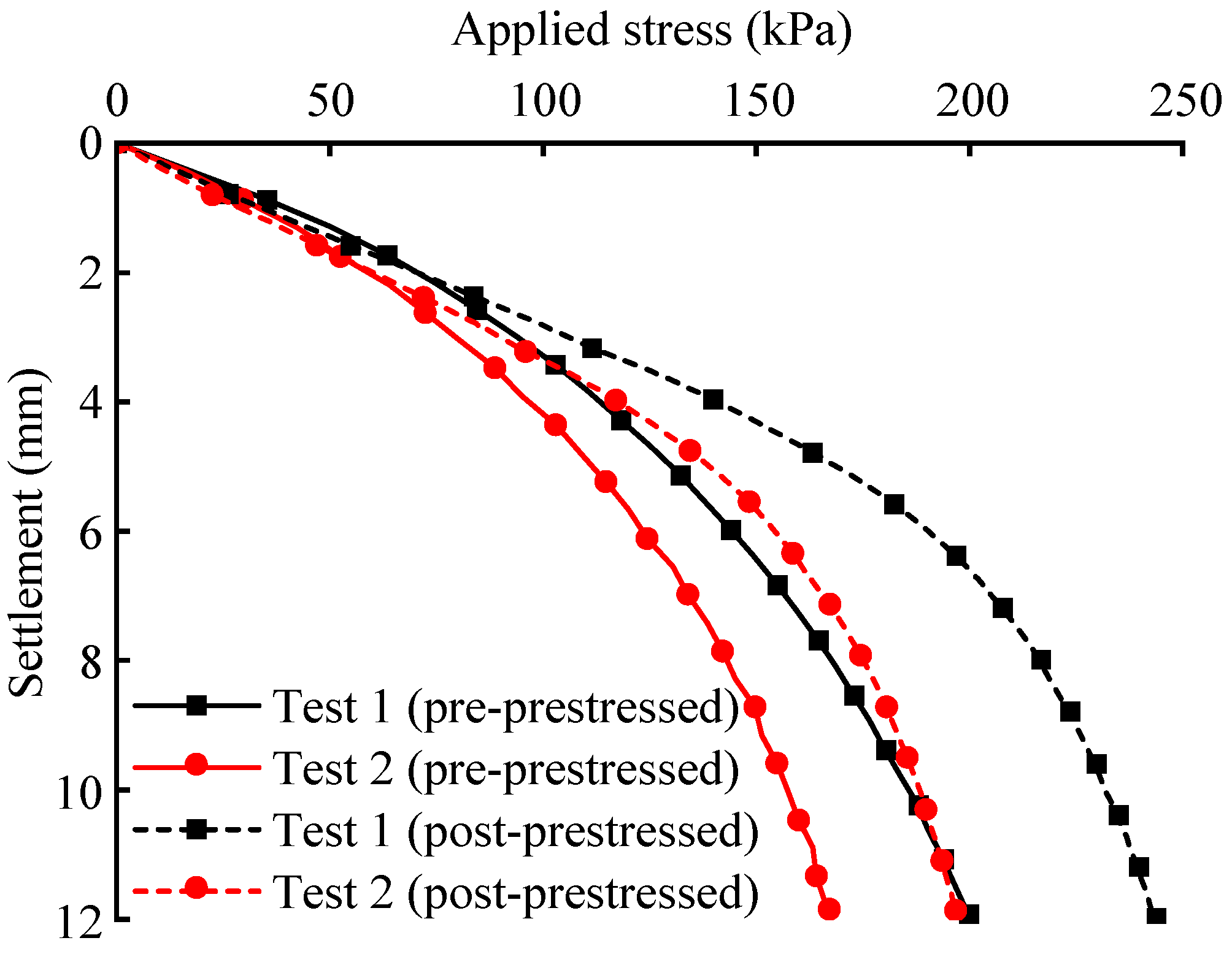
The load–settlement curves for pre-prestressed phase and post-prestressed phase in both tests are shown in
Figure 7. As observed, the initial slopes of the load–settlement curves for both tests are similar during pre-prestressed phase. This is because, at lower applied loads, the additional stress transferred to the geosynthetic-reinforced soil and sheet pile wall is minimal, and the load is mainly supported by the embankment fill. As a result, the structural performance of the sheet pile wall is not fully utilized. In the later stages of loading, the larger pile spacing in Test 2 results in a lower anchoring force provided by the piles, leading to a smaller load carried at the same settlement. When the settlement reaches 12.4 mm, the ultimate bearing capacity for Test 1 is 202.068 kPa, while for Test 2, it is 169.485 kPa, a 16.1% decrease. Under the compaction effect of preloading, when the settlement of post-prestressed phase reaches 0.1 b, the ultimate bearing capacities for Tests 1 and 2 are 245.849 kPa and 197.535 kPa, respectively, showing increases of 21.7% and 16.6% compared to pre-prestressed phase. The “prestress” effect enhances the compaction of the soil, its elastic modulus, and the interaction between the reinforcement and soil, resulting in a higher ultimate bearing capacity during post-prestressed phase than during pre-prestressed phase. However, the effect of preloading is not significant in small settlements. As the settlement increases, the improvement in soil stiffness, bearing capacity, and deformation ability gradually becomes more apparent.
3.2. Pile Horizontal Displacement
The horizontal displacement at the top and midpoint of the cantilever segment of the central pile under pre-prestressed phase and post-prestressed phase in Test 1 is shown in
Figure 8. The displacement trend is similar for both pre-prestressed phase and post-prestressed phase. Under loads of 0–30 kPa, the horizontal displacement of the pile remains relatively constant. After this point, the displacement increases more rapidly as the load increases. This behavior suggests that similar to traditional sheet pile wall structures, the “prestressed” geosynthetic-reinforced sheet pile retaining wall undergoes two stages: compression and deformation under load. Under the combined effects of the load and the embankment fill’s weight, the geosynthetic-reinforced soil is compacted and undergoes settlement. The diffusion of additional stress induces horizontal earth pressure behind the sheet pile wall, causing horizontal displacement.
The displacement of the pile heads for both tests is shown in
Figure 9. Increasing the pile spacing leads to larger pile head displacements. At a load of 150 kPa, Test 2 shows a 25.5% increase in pile head horizontal displacement during pre-prestressed phase compared to Test 1 and a 35.9% increase during post-prestressed phase. The application of “prestress” effectively controls the horizontal displacement of the reinforced composite embankment sheet pile wall, even with varying pile spacings. In Test 1, during the post-prestressed phase at 150 kPa, the horizontal displacement at the pile top is 1.11 mm, which represents a reduction of 54.3% compared to the pre-prestressed phase. Similarly, in Test 2, the reduction is 53.7%. These results demonstrate that “prestress” significantly mitigates the horizontal displacement of the sheet pile wall in the reinforced embankment.
3.3. Horizontal Earth Pressure
The distribution of horizontal earth pressure on the sheet pile wall during the pre-prestressed phase and post-prestressed phase in Test 1 is shown in
Figure 10. The figure shows the horizontal earth pressure behind the sheeting plate in the upper-left corner, and the horizontal earth pressures on the left and right sides of the pile in the lower-left and lower-right corners, respectively. In both loading phases, the maximum horizontal earth pressure occurs 20 cm from the pile bottom on the right side. At ultimate load, the horizontal earth pressures at these points are 82.37 kPa and 93.3 kPa, respectively. This is because, under the applied load, the pile body tilts further to the right, causing the soil on the right to bear more pressure. The load at the bottom of the sheeting plate is greater than at the center. This is partly because the bottom of the sheeting plate undergoes less deformation, which limits the deformation of the soil. As the panel deforms from the bottom upwards, the earth pressure is gradually released. Additionally, the external load induces a diffusion effect on earth pressure within the embankment, with the bottom of the sheeting plate falling within this diffusion zone. This results in a higher earth pressure at the bottom than at the center.
The “prestress” does not change the distribution pattern of the earth pressure at both loading phase. However, the maximum horizontal earth pressure during post-prestressed phase is higher than during pre-prestressed phase. After the soil is compacted during preloading, its deformation is constrained, reducing pile displacement and increasing the horizontal earth pressure on the pile. Furthermore, increasing the pile spacing (Test 2) results in a earth pressure distribution on both sides of the sheet pile wall that is nearly identical to Test 1, with a slight reduction in earth pressure on the right side. This suggests that changes in pile spacing have a minimal impact on pile-side earth pressure.
3.4. Pile Bending Moment
The strain on both sides of the pile at the same height was measured during the experiment. Using Equations (3) and (4), the pile curvature [
33] and bending moment were calculated as follows:
where
z is the vertical distance from the pile top at a specific location,
is the strain difference between the back of the pile and the pile surface at that location, measurable from strain gauges,
a is the height of the pile section (with a value of 0.06 m), and
EI is the pile’s bending stiffness.
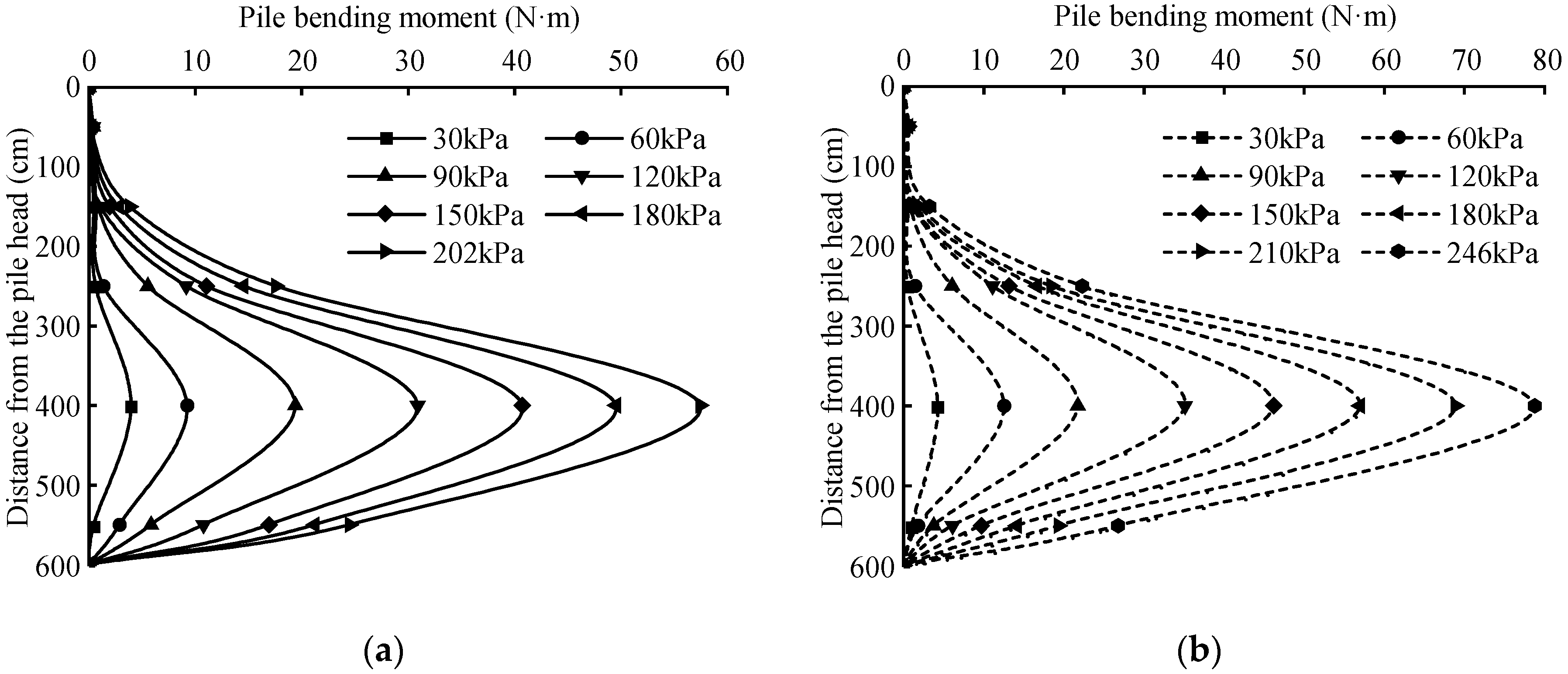
The distribution curves of the pile bending moment for the “prestressed” geosynthetic-reinforced sheet pile retaining wall during the pre-prestressed phase and post-prestressed phase in Test 1 are shown in
Figure 11. During the post-prestressed phase, the maximum bending moment at each load stage is greater than during the pre-prestressed phase, indicating that “prestress” strengthens the interaction between the sheet pile wall and the soil, thereby enhancing the overall stability of the structure. The bending moment distribution along the pile is similar in both loading phases, with the maximum bending moment occurring in the anchorage section of the pile. The bending moment increases gradually from 150 mm below the pile top, reaches a maximum at 400 mm, and then decreases rapidly as the depth exceeds 400 mm, approaching zero at the pile bottom. This trend corresponds with the distribution of earth pressure on the right side of the pile’s anchorage section. Increasing the pile spacing (Test 2) does not change the bending moment distribution but increases the maximum bending moment for each load stage. This is because, as the pile spacing increases, the effective load width of the pile also increases, resulting in larger shear and bending moments acting on the pile.
3.5. Reinforcement Strain
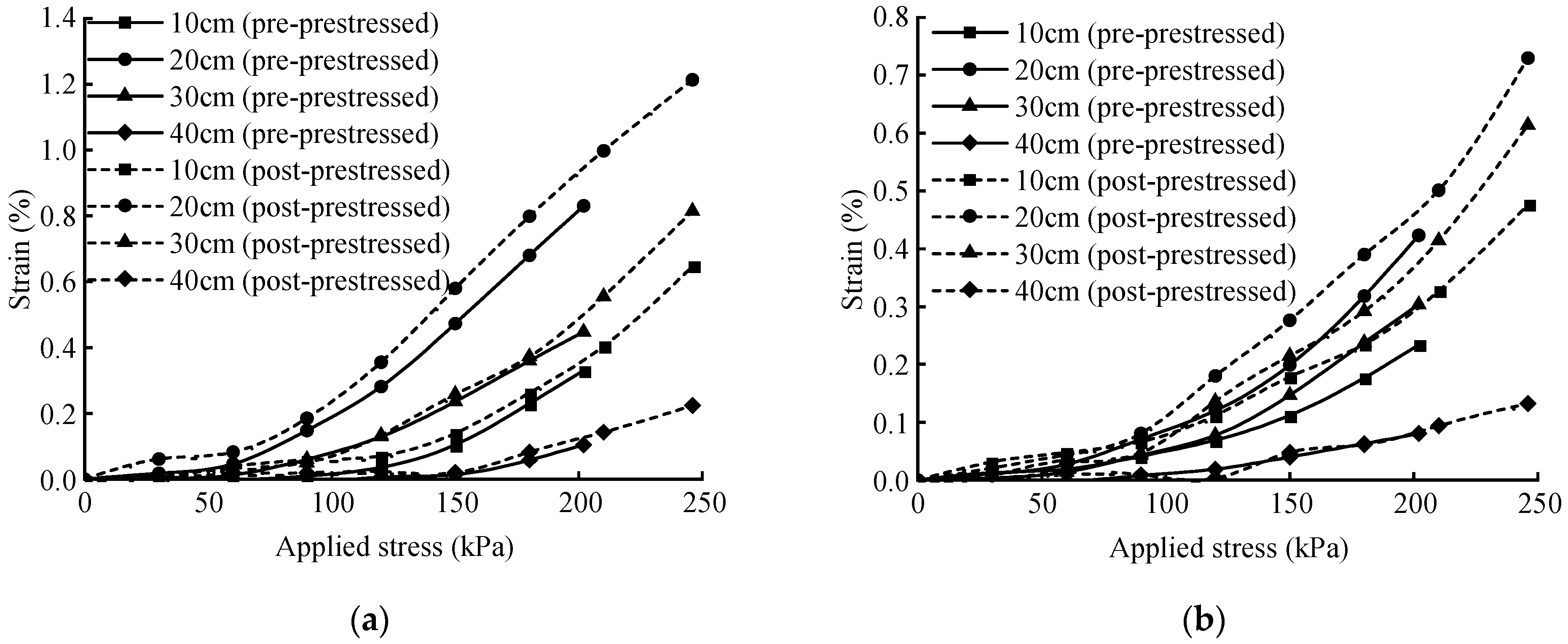
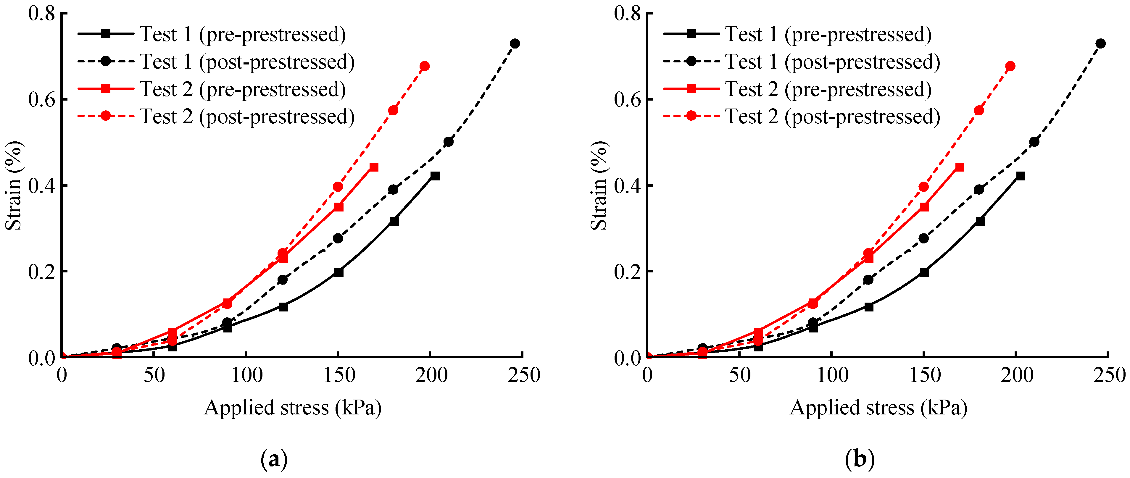
In this experiment, two layers of reinforcement were placed in the embankment soil. The strain of the reinforcement during the pre-prestressed phase and post-prestressed phase in Test 1 is shown in
Figure 12. The maximum strain in each layer occurs 20 cm from the sheeting plate. During the early stages of both loading phases, when the external load is less than 30 kPa, the strain in the reinforcement is negligible. This indicates that the reinforcement strength in the “prestressed” geosynthetic-reinforced sheet pile retaining wall structure becomes significant only after a certain level of applied load.
During the pre-prestressed phase, at loads of 150 kPa and 180 kPa, the maximum strain in the upper reinforcement layers is 0.47% and 0.68%, respectively. In the lower layers, the maximum strain is 0.20% and 0.32%. During the post-prestressed phase, at the same loads (150 kPa and 180 kPa), the strain in the upper layers increases to 0.58% and 0.80%, while in the lower layers, the strain increased to 0.28% and 0.39%. The strain during the post-prestressed phase is higher than during the pre-prestressed phase because, after applying “prestress”, the soil’s compaction increases, tightening the soil reinforcement interaction. In both tests, the strain in the lower reinforcement layers is smaller because the additional stress caused by the load decreases with depth, resulting in less tensile strength in the reinforcement at the bottom.
The comparison of reinforcement strain in both tests is shown in
Figure 13. In Test 2, at a load of 150 kPa, the maximum strain in the upper and lower reinforcement layers is 0.64% and 0.35% during the pre-prestressed phase, respectively. During the post-prestressed phase, the maximum strain increases to 0.67% and 0.40%. The geosynthetic reinforcement layers in the embankment are connected to the sheet pile wall; they transfer tensile forces to the wall to restrain its lateral movement. However, doubling the pile spacing reduces the anchoring force provided to the embankment, which results in significantly higher strains in both the upper and lower reinforcement layers compared to Test 1.
4. Conclusions
This study, through two sets of model tests on “prestressed” geosynthetic-reinforced sheet pile retaining wall structures, demonstrated the strengthening effect of prestress. The research analyzed the load-settlement characteristics, horizontal displacement of the cantilever segment of the pile, distribution of horizontal earth pressure along the depth of the sheet pile wall, pile bending moment distribution, and strain development in reinforcements at various locations. The key findings are as follows:
(1) Prestress improves the bearing and deformation performance of reinforced composite embankment sheet pile wall structures. After applying prestress, the bearing capacity of the two test groups increases by 21.7% and 16.6%, respectively.
(2) The application of prestress reduces the horizontal displacement of the sheet pile wall during the post-prestressed phase. However, increasing the pile spacing (i.e., weakening the support conditions) negatively affects the deformation performance of the prestressed reinforced composite embankment sheet pile wall structure, causing the horizontal displacement of the pile’s cantilever segment to increase.
(3) The application of prestress increases the horizontal earth pressure acting on the pile, enhancing the retaining function of the sheet pile wall. The horizontal earth pressure distribution on the right side of the pile is significantly greater than on the left, with the maximum horizontal earth pressure occurring 20 cm from the pile bottom on the right side. Increasing the pile spacing in the prestressed reinforced composite embankment sheet pile wall structure has little effect on the maximum horizontal earth pressure on the pile.
(4) The maximum bending moment of the pile occurs at the anchorage section, and its distribution is consistent with the earth pressure distribution on the right side of the pile. After applying prestress, the maximum bending moment of the pile increases slightly.
(5) Prestress enhances the interaction between the reinforcement and soil, allowing the reinforcement to develop greater tensile strength. Increasing the pile spacing in the prestressed reinforced composite embankment sheet pile wall structure results in increased strain in the reinforcement.
Author Contributions
Conceptualization, Y.L. and K.L.; experimental design, Y.L. and T.Y.; data curation, T.Y.; writing—original draft preparation, X.T.; visualization, X.T.; revising and editing the final version K.L. and Z.S.; resources, Z.S.; supervision, K.L. All authors have read and agreed to the published version of the manuscript.
Funding
This research was funded by the National Natural Science Foundation of China (Grant No. 52478363).
Data Availability Statement
The datasets generated during the current study are available from the corresponding author upon reasonable request.
Conflicts of Interest
Author Tengfei Yan was employed by the company China Railway First Survey and Design Institute Group Co., Ltd. Author Yong Liu and Zhilong Shi were employed by the company China Railway Eryuan Chongqing Survey and Design Institute Co., Ltd. The remaining authors declare that the research was conducted in the absence of any commercial or financial relationships that could be construed as a potential conflict of interest.
References
- Bosscher, P.J.; Gray, D.H. Soil arching in sandy slopes. Int. J. Rock. Mech. Min. 1986, 112, 626–645. [Google Scholar] [CrossRef]
- Stewart, D.P.; Jewell, R.J.; Randolph, M.F. Design of piled bridge abutments on soft clay for loading from lateral soil movements. Geotechnique 1994, 44, 277–296. [Google Scholar] [CrossRef]
- Gopal Madabhushi, S.P.; Chandrasekaran, V.S. Rotation of cantilever sheet pile walls. J. Geotech. Geoenviron. 2005, 131, 202–212. [Google Scholar] [CrossRef]
- Huang, Z.; Zhang, Y.; Dong, J. Experimental study of soil arching and transfer behavior of earth pressure about sheet-pile walls. Rock Soil Mech. 2013, 34, 1887–1892. [Google Scholar]
- Cherubini, C.; Garrasi, A.; Petrolla, C. The reliability of an anchored sheet-pile wall embedded in a cohesionless soil. Can. Geotech. J. 1992, 29, 426–435. [Google Scholar] [CrossRef]
- Zhu, X.; Huang, X. Laboratory simulating test and field settlement observation of reinforced embankment. Chin. J. Geotech. Eng. 2002, 3, 386–388. [Google Scholar]
- Yang, Q.; Ji, D.; Luan, M.; Zhang, K. Studies on structural performance of embankment slopes reinforced by geogrids with model tests. Rock Soil Mech. 2005, 8, 1243–1246. [Google Scholar]
- Banerjee, L.; Chawla, S.; Bhandari, G. Experimental and 3-D finite element analyses on geocell-reinforced embankments. J. Test. Eval. 2018, 47, 1876–1899. [Google Scholar] [CrossRef]
- Zhang, L.; Ou, Q.; Zhao, M.; Ding, X.; Liu, J. Numerical analysis of dynamic response characteristics of geosynthetics-reinforced embankment under moving load. Rock Soil Mech. 2021, 42, 2865–2874. [Google Scholar]
- Lackner, C.; Bergado, D.T.; Semprich, S. Prestressed reinforced soil by geosynthetics—Concept and experimental investigations. Geotext. Geomembr. 2013, 37, 109–123. [Google Scholar] [CrossRef]
- Ahmadi, H.; Bezuijen, A.; Zornberg, J.G. Interaction mechanisms in small-scale model MSE walls under the strip footing load. Geosynth. Int. 2021, 28, 238–258. [Google Scholar] [CrossRef]
- Uchimura, T.; Tateyama, M.; Tanaka, I.; Tatsuoka, F. Performance of a preloaded-prestressed geogrid-reinforced soil pier for a railway bridge. Soils Found. 2003, 43, 155–171. [Google Scholar] [CrossRef] [PubMed]
- Lovisa, J.; Shukla, S.K.; Sivakugan, N. Behaviour of prestressed geotextile-reinforced sand bed supporting a loaded circular footing. Geotext. Geomembr. 2010, 28, 23–32. [Google Scholar] [CrossRef]
- Lu, L.; Tang, T.; Wang, Z. Experimental study of modeling prestressed reinforced embankment to reduce differential settlement. J. Cent. South Univ. (Nat. Sci. Ed.) 2020, 51, 1883–1892. [Google Scholar]
- Roh, H.S.; Tatsuoka, F. Effects of preloading and prestressing on the strength and stiffness of geosynthetic reinforced clay in plane strain compression. Geosynth. Int. 2001, 8, 393–444. [Google Scholar] [CrossRef]
- Shinoda, M.; Uchimura, T.; Tatsuoka, F.; Tateyama, M.; Natsuki, T. A new simple method to substantially increase the seismic stability of reinforced soil structures. Soil Dyn. Earthq. Eng. 2002, 22, 1115–1123. [Google Scholar] [CrossRef]
- Ma, S.; Lu, L.; Wang, Z.; Wang, J.; Li, L. Deformation and load transmission mechanism of prestressed reinforced embankment subjected to rockfall impacts. Rock Soil Mech. 2023, 44, 709–809. [Google Scholar]
- TB 10001-2016; Code for Design of Railway Earth Structure. National Railway Administration: Beijing, China, 2017.
- LRFDBDS-9; LRFD bridge design specification. American Association of State Highway and Transportation Officials (AASHTO): Washington, DC, USA, 2020.
- FHWA-NHI-10-024; Design and construction of mechanically stabilized earth walls and reinforced soil slopes—Volume I. Federal Highway Administration: Washington, DC, USA, 2009.
- TB 10025-2019; Code for design of retaining structures of railway earthworks. National Railway Administration: Beijing, China, 2019.
- JTG D30-2015; Specifications for design of highway subgrades. Ministry of Transport of the People’s Republic of China: Beijing, China, 2015.
- Yang, G.; Lv, P.; Pang, W.; Yu, Z. Research on geogrid reinforced soil retaining wall with wrapped face by in-situ tests. Rock Soil Mech. 2008, 29, 517–522. [Google Scholar]
- Wu, L.; Yang, G.; Zhang, Q.; Sun, H.; Zhang, L.; Jiao, R.; Su, Q. In-situ test on dynamic responses of reinforced soil retaining walls for high-speed railways. J. Southwest Jiaotong Univ. 2017, 52, 546–553. [Google Scholar]
- Xu, C.; Lou, Y.S.; Zhu, H.; Wang, J.; Yang, F. Performance of high geosynthetic-reinforced embankments. In Proceedings of the Geo-Congress on Stability and Performance of Slopes and Embankments, San Diego, CA, USA, 3–7 March 2013; pp. 515–518. [Google Scholar]
- Eftekhari, Z.; Panah, A.K. 1-g shaking table investigation on seismic performance of polymeric-strip reinforced-soil retaining walls built on rock slopes with limited reinforced zone. Soil Dyn. Earthq. Eng. 2021, 147, 106758. [Google Scholar] [CrossRef]
- Yazdandoust, M.; Jamnani, A.R.; Sabermahani, M. Dynamic evaluation of tiered geogrid mechanically stabilized earth (MSE) walls using shake table test. Acta Geotech. 2023, 19, 4139–4165. [Google Scholar] [CrossRef]
- Liu, K.; Shao, K.; El Naggar, M.H.; Su, Q.; Wang, T.; Qiu, R. Dynamic performance of a railway subgrade reinforced by battered grouted helical piles. J. Geotech. Geoenviron. Eng. 2024, 10, 05024009. [Google Scholar] [CrossRef]
- Zheng, Y.W.; Li, F.X.; Guo, W.H.; Wang, P.; Yang, G. Influence of facing conditions on the dynamic response of back-to-back MSE walls. Soil Dyn. Earthq. Eng. 2023, 164, 107650. [Google Scholar] [CrossRef]
- Louati, H.; Oulahna, D.; de Ryck, A. Apparent friction and cohesion of a partially wet granular material in steady-state shear. Powder Technol. 2015, 278, 65–71. [Google Scholar] [CrossRef]
- TB 10102-2010; Code for soil test of railway engineering. Ministry of Railways of the People’s Republic of China: Beijing, China, 2010.
- ASTM D4595-17; Standard test method for tensile properties of geotextiles by the wide-width strip method 1. American Society for Testing Materials: West Conshohocken, PA, USA, 2017.
- Huang, F.; Zhang, F.; Shan, Y.; Lin, Y.; Zhou, Z. Calculation method of internal force of integral abutment pile foundation-soil interaction. China J. Highw. Transp. 2021, 34, 69–79. [Google Scholar]
| Disclaimer/Publisher’s Note: The statements, opinions and data contained in all publications are solely those of the individual author(s) and contributor(s) and not of MDPI and/or the editor(s). MDPI and/or the editor(s) disclaim responsibility for any injury to people or property resulting from any ideas, methods, instructions or products referred to in the content. |
© 2025 by the authors. Licensee MDPI, Basel, Switzerland. This article is an open access article distributed under the terms and conditions of the Creative Commons Attribution (CC BY) license (https://creativecommons.org/licenses/by/4.0/).


