1. Introduction
In the contemporary era, the swift pace of urbanization and the continuous evolution of construction technologies have led to a significant increase in the demand for high-rise buildings and large-scale infrastructures. The stability and safety of these structures are largely contingent upon the quality of their foundation design [
1,
2,
3]. Pile foundations, as fundamental components supporting structures, are capable of transferring loads from upper structures to deeper soil layers, effectively limiting the settlement of the upper structures, thereby addressing the issue of insufficient bearing capacity in shallow foundations [
4,
5]. This has resulted in the widespread application of pile foundations in high-rise buildings and marine engineering constructions [
6,
7,
8,
9]. Owing to the notable advantages of pile groups in bearing capacity, settlement control, and structural stability, they have become the preferred solution in actual engineering constructions, especially in weak foundations or soil layers with limited bearing capacity [
10,
11]. However, due to the complexity of geological conditions and the diversity of construction techniques, the interaction between piles and soil has emerged as one of the crucial factors influencing structural stability [
12,
13]. In particular, when multiple piles work together to form a pile group system, the interactions between piles, and between piles and the surrounding soil, become even more intricate, directly impacting the safety performance of the entire structure [
14,
15].
In recent years, numerous studies have been conducted to explore the pile–soil interaction and group pile effect [
16,
17,
18,
19]. Comodromos and Pitilakis [
20] investigated the interactions between pile groups under different numbers of piles, pile spacings, and horizontal displacement conditions. They found that the load distribution and deformation behavior of pile groups are significantly influenced by these factors. Additionally, researchers such as Zhang and Wei [
21] and Fu and Jiang [
22] have conducted experimental and numerical studies to analyze the lateral behavior of piled bridge foundations and stabilizing piles on steep slopes. Their results indicated that the pile–soil interaction plays a vital role in the load-carrying capacity and stability of these structures. Furthermore, Qiu and Wang [
23] have explored the vertical and horizontal bearing characteristics of pile groups in different soil conditions, highlighting the complexity of the group pile effect. More recently, studies by Ma and Mou [
24] and Jiang and Zhang [
25] have focused on the bearing behavior of various types of pile foundations, providing valuable insights into the mechanical behavior of pile–soil systems. These studies collectively emphasize the importance of considering pile–soil interactions and group pile effect in the design and analysis of pile foundations.
Despite the extensive research conducted so far, there are still some gaps in the existing literature. Most of the previous studies have focused on either single-pile or pile group foundations under specific conditions, and limited attention has been given to the comprehensive analysis of pile–soil interaction and group pile effect under different pile length conditions in composite foundations [
26,
27,
28]. For instance, while Comodromos and Pitilakis [
20] provided a detailed analysis of the horizontal load response of pile groups, their study was limited to a specific soil type and pile configuration. Similarly, Zhang and Wei [
21] and Fu and Jiang [
22] focused on lateral pile behavior but did not explore the impact of varying pile lengths on the overall composite foundation performance. Qiu and Wang [
23] highlighted the bearing characteristics of pile groups in different soil conditions but did not delve into the detailed interaction mechanisms under varying pile lengths.
It is worth noting that the reliability of simulations in geotechnical systems has been a topic of interest [
29,
30]. The primary objective of this study is to conduct a comprehensive analysis of the pile–soil interaction and group pile effect in composite foundations under various pile length conditions using FLAC3D numerical simulation. Specifically, we aim to investigate how different pile lengths influence the settlement, bearing capacity, and stress distribution of pile group composite foundations. In doing so, we hope to provide a more detailed understanding of the underlying mechanisms and offer practical guidance for the design and optimization of pile group composite foundations in real-world engineering applications. The results of this study are expected to fill the existing gaps in the literature and provide a valuable theoretical basis for improving the performance of pile group composite foundations.
2. Construction of Computational Model
To gain an in-depth understanding of the pile–soil interaction and mechanical behavior of pile group composite foundations under different pile length conditions, a detailed three-dimensional computational model was constructed using the numerical simulation method [
31,
32,
33]. The design of the model took into account the geological conditions in actual engineering, the layout of pile foundations, and the load transfer path, striving to accurately reflect the working characteristics of pile group composite foundations in numerical simulations.
2.1. Geometric Dimensions and Mesh Division of the Model
The geometric dimensions of the model were designed based on the layout of raft foundations and pile foundations in actual engineering. In the horizontal direction, the size of the model was taken as six times the width of the raft foundation to minimize the influence of boundary effects on load transfer. The vertical size was set at twice the thickness of the soil layer above the mudstone, specifically 70 m, to cover the complete soil layer structure from the ground surface to the pile end embedded layer. The pile lengths in the model were 3.5 m, 8.5 m, 13.5 m, 18.4 m, 23.4 m, 28.4 m, and 33.4 m, covering various working conditions, from short piles to long piles, as shown in
Figure 1. The pile diameter was uniformly 600 mm, and the pile spacing was 3D (i.e., 1.8 m) to simulate the common pile arrangement in actual engineering. Due to the symmetry of the model, only one-fourth of the model was taken for modeling and analysis to improve computational efficiency. Ultimately, the FLAC3D model contained 200,904 zones and 209,844 grid points. The mesh division fully considered the geometric characteristics and mechanical properties of the pile body, soil body, and pile–soil contact surface to ensure the accuracy and reliability of the computational results, as shown in
Figure 2.
To ensure the accuracy and reliability of the numerical simulation results, a mesh sensitivity analysis was conducted. The mesh sensitivity analysis is crucial for determining the appropriate mesh density to provide accurate results without excessive computational cost. Initially, a coarse mesh was used to establish a baseline for the simulation results. Subsequently, the mesh was refined in stages, and the results were compared at each stage. The refinement process focused on critical areas such as the pile–soil interface and regions of high stress gradients. The analysis revealed that further refinement of the mesh beyond a certain point did not significantly alter the results, indicating that the chosen mesh density was sufficient to capture the essential features of the pile–soil interaction and group pile effect. The final mesh configuration, which included 200,904 zones and 209,844 grid points, was selected based on this sensitivity analysis to balance computational efficiency and result accuracy.
The boundary conditions of the model were designed to take into account the actual force environment in engineering. In the horizontal direction, horizontal displacement constraints were applied to the two side boundaries of the model to simulate the lateral constraint conditions of the actual foundation. Specifically, the horizontal displacement was set to zero at these boundaries. At the bottom boundary, full constraints were applied to simulate the contact relationship between the foundation and the underlying layer, meaning that both horizontal and vertical displacements were set to zero. The vertical boundary allowed free deformation to reflect the deformation characteristics of the actual foundation under vertical loads. Loads were applied uniformly to the pile tops and soil between piles through the raft foundation to simulate the vertical loads transmitted from the upper structure. During the loading process, a stepwise loading method was used to gradually increase the load while recording the model’s responses at different load levels, including key parameters such as settlement, stress distribution, and pile–soil interaction.
2.2. Selection of Computational Parameters
The geotechnical parameters in the model were determined based on actual engineering geological survey data, covering various soil layer types from the ground surface to the mudstone layer, including subgrade, gravel, coarse sand, medium sand, fine sand, gravel sand, silt, silty clay, pebbles, and strongly weathered sandy mudstone. The physical and mechanical parameters (such as elastic modulus, Poisson’s ratio, cohesion, internal friction angle, and density) of each soil layer were reasonably valued according to on-site tests and literature data, as shown in
Table 1. The selection of these parameters not only reflects the complexity of actual geological conditions, but also provides an accurate mechanical basis for simulating pile–soil interaction. In the FLAC3D model, the pile foundation was simulated using solid pile elements, which can truly reflect the stress–strain characteristics of the pile body during the loading process. The material properties of the pile elements were defined according to the mechanical parameters of the actual pile material, including elastic modulus, Poisson’s ratio, and density. The soil was simulated using the Mohr–Coulomb elastoplastic constitutive model in FLAC3D, which can effectively describe the nonlinear deformation and yielding characteristics of the soil during the loading process. The treatment of the pile–soil contact surface is one of the key parts of the model. By defining the contact elements between the pile and soil, the friction and embedment between the pile and soil were considered to ensure that the load could be reasonably transferred from the pile body to the soil.
3. Pile–Soil Interaction in Pile Group Composite Foundations
3.1. Settlement of Pile Group Foundations
The settlement of the raft center under different loads was recorded, as shown in
Figure 3. Under the same load, an increase in pile length significantly reduced the settlement of the raft. When the pile length was below 23.4 m, the settlement of the composite foundation increased sharply, indicating that the composite foundation had reached or was close to its bearing capacity limit, i.e., the composite foundation was in a critical state of instability. However, when the pile length exceeded 23.4 m, the pile tips contacted or were embedded in the mudstone layer, enhancing the load-bearing capacity of the piles and their resistance to deformation. As a result, the entire composite foundation system could withstand greater loads without becoming unstable. The observed reduction in settlement with increasing pile length can be attributed to the enhanced load transfer mechanism. Longer piles penetrate deeper into the soil, reaching more competent layers (such as the strongly weathered sandy mudstone layer in this study). This deeper embedment increases the effective area over which the load is distributed, thereby reducing the unit stress on the soil and improving the overall stability of the foundation. Additionally, the increased pile length allows for greater mobilization of the soil’s shear strength along the pile shaft, which further enhances the load-bearing capacity of the composite foundation.
When the pile length was relatively short, the pile tips failed to establish an effective connection with the mudstone layer, preventing the piles from fully utilizing the support of the underlying strata. Consequently, under significant loads, excessive settlement was likely to occur. However, once the pile length surpassed a certain threshold (i.e., 23.4 m), the pile tips could establish a stable embedded relationship with the strongly weathered sandy mudstone layer, significantly enhancing the overall stability of the piles. This embedding not only increased the load-bearing capacity of the piles, but also strengthened the interaction between the piles and the surrounding soil, enabling the composite foundation to function as a more effective load-bearing and deformation control system. Therefore, in actual engineering design and construction, considering the complexity of geological conditions, it is essential to ensure that the pile tips are embedded to a certain depth in the strongly weathered sandy mudstone layer to guarantee the proper functioning of the composite foundation system.
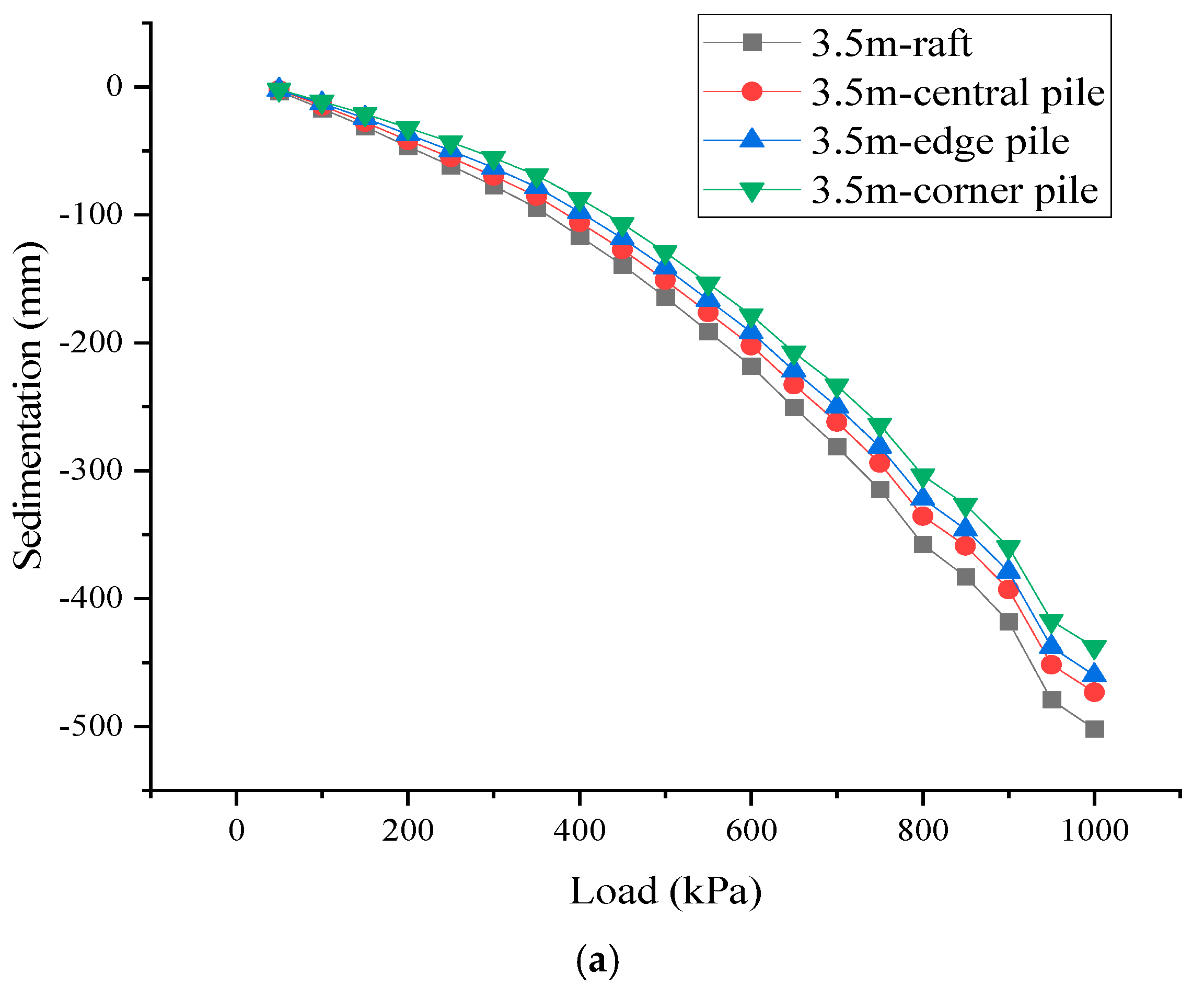
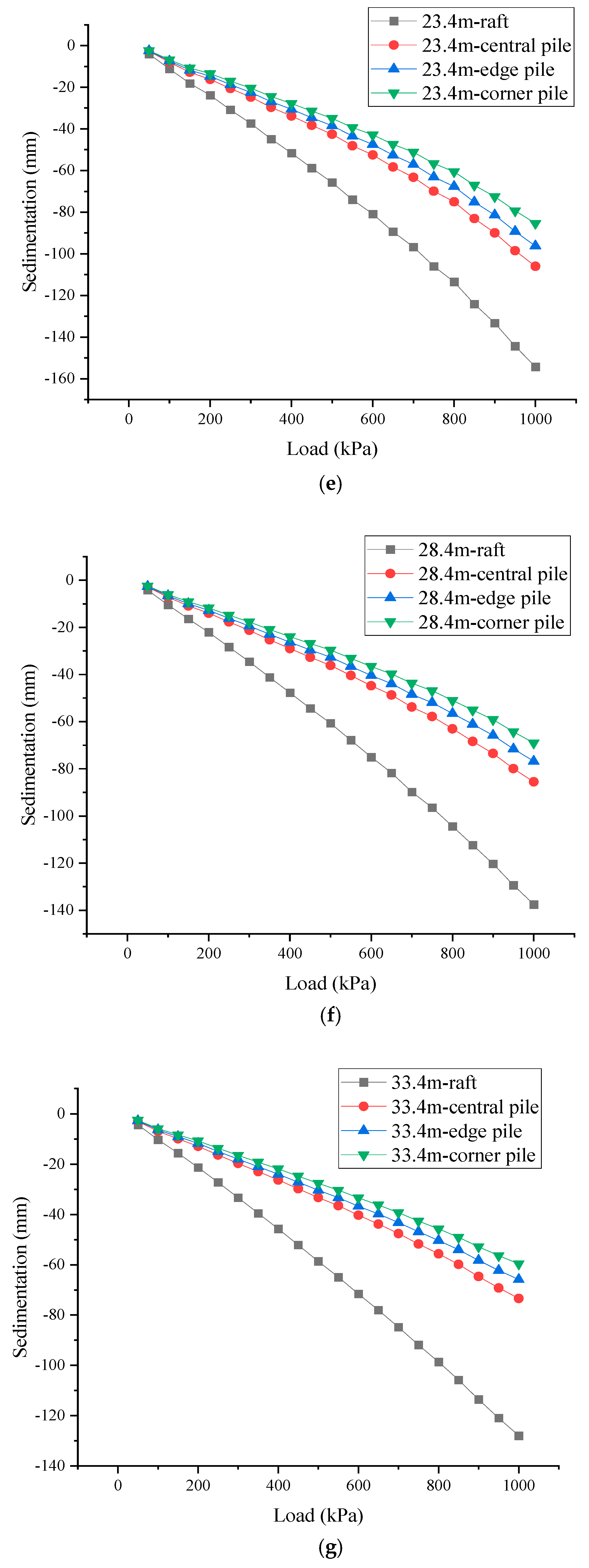
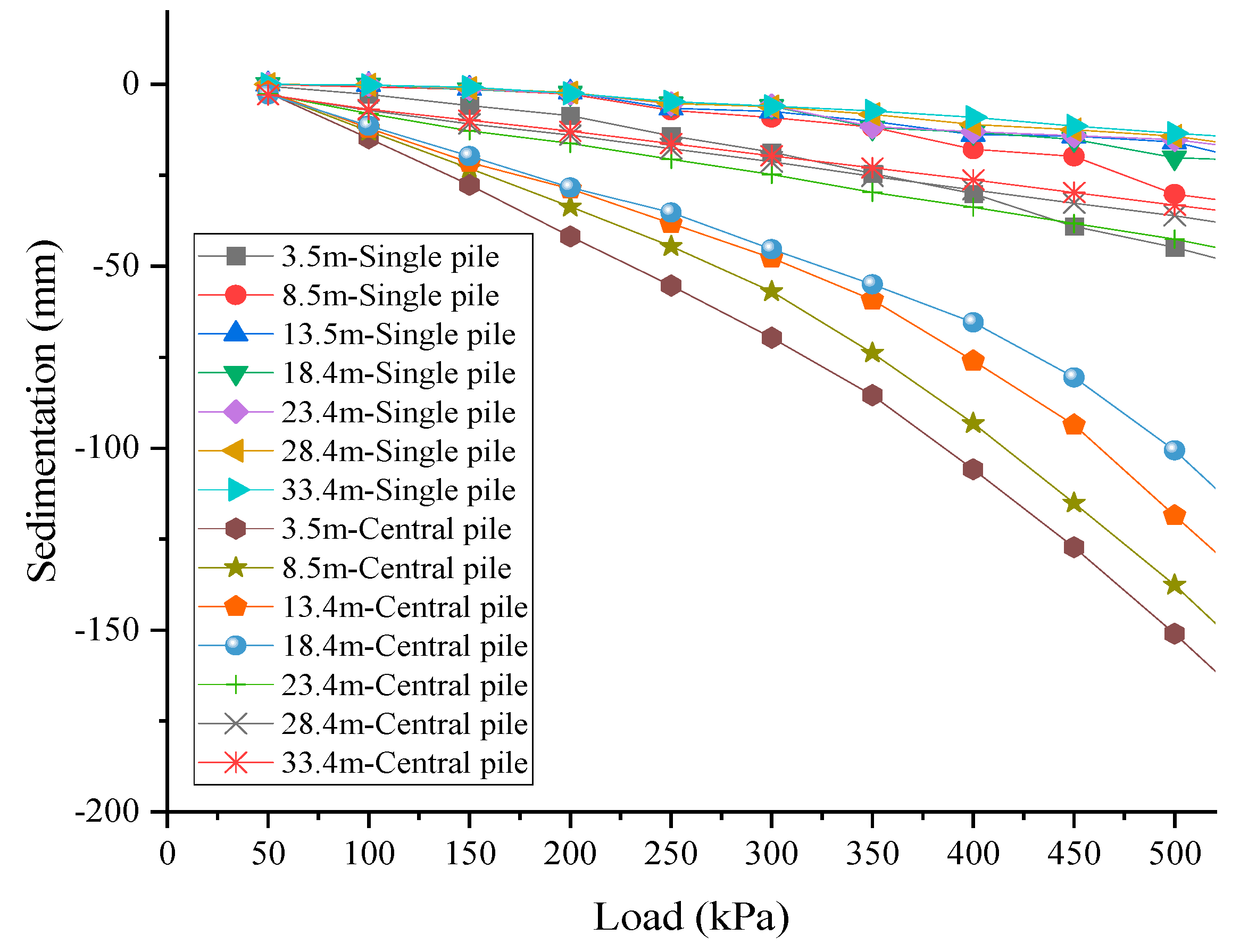
Under different loads, the settlement curves of the center points of the top surfaces of the central piles, intermediate piles, edge piles, and corner piles are shown in
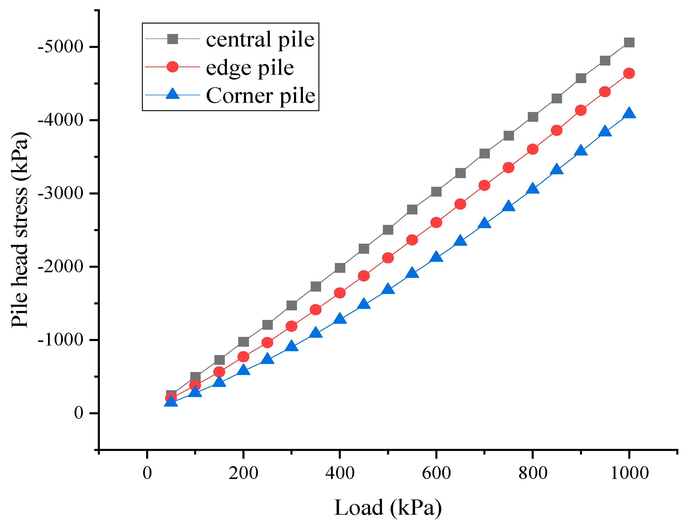
Figure 4. Under various loads, the pile foundations of the raft foundation system exhibited different settlement characteristics. The settlement of the central piles was the most significant, followed by the edge piles, while the settlement of the corner piles was the smallest. This differential settlement phenomenon, i.e., the existence of settlement differences among piles at different locations on the same raft, became more pronounced as the applied load increased. This was because, in the initial loading stage, the stress at the top of the central piles was the highest, followed by the edge piles, and the corner piles had the lowest stress. This was mainly due to the fact that the soil surrounding the edge and corner piles, compared to that around the central piles, was less constrained and could more easily disperse part of the load into the surrounding soil. In contrast, the central piles, being in the middle of the raft, were surrounded by soil that was more constrained, making it difficult for the stress to effectively diffuse. As a result, the central piles experienced a higher stress level. When the pile length increased, the settlement difference between the central and corner piles decreased. This indicated that as the pile length grew, the interaction mode between the pile foundations and the surrounding soil changed. Longer piles might imply greater side frictional resistance or more complex interaction mechanisms with the soil, which together made the load distribution more uniform, thereby reducing the settlement differences caused by different positions. In addition, for a specific pile length, such as 33.4 m (
Figure 5), the central piles experienced the highest stress during the initial loading, followed by the edge and corner piles. Therefore, in designing pile foundations, attention should be paid to the design parameters of the central piles to ensure the safety and stability of the entire structure.
3.2. Axial Stress of Piles
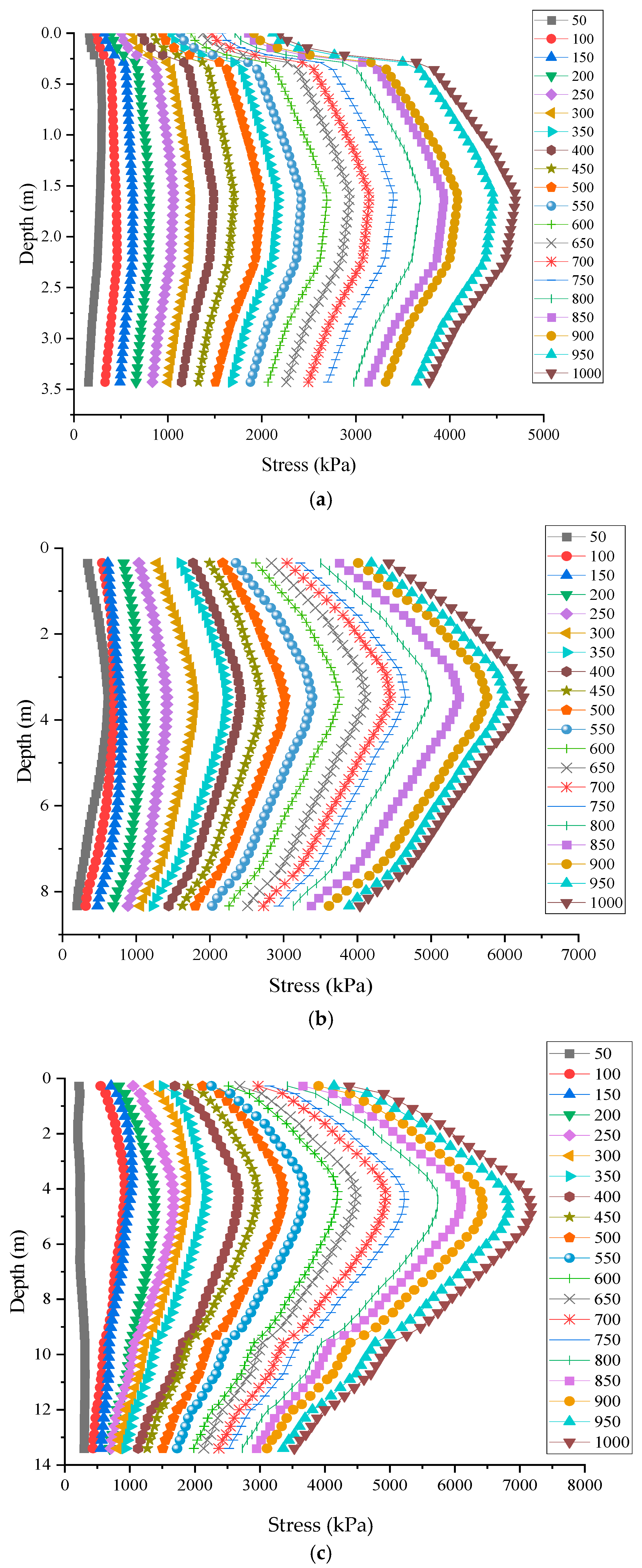
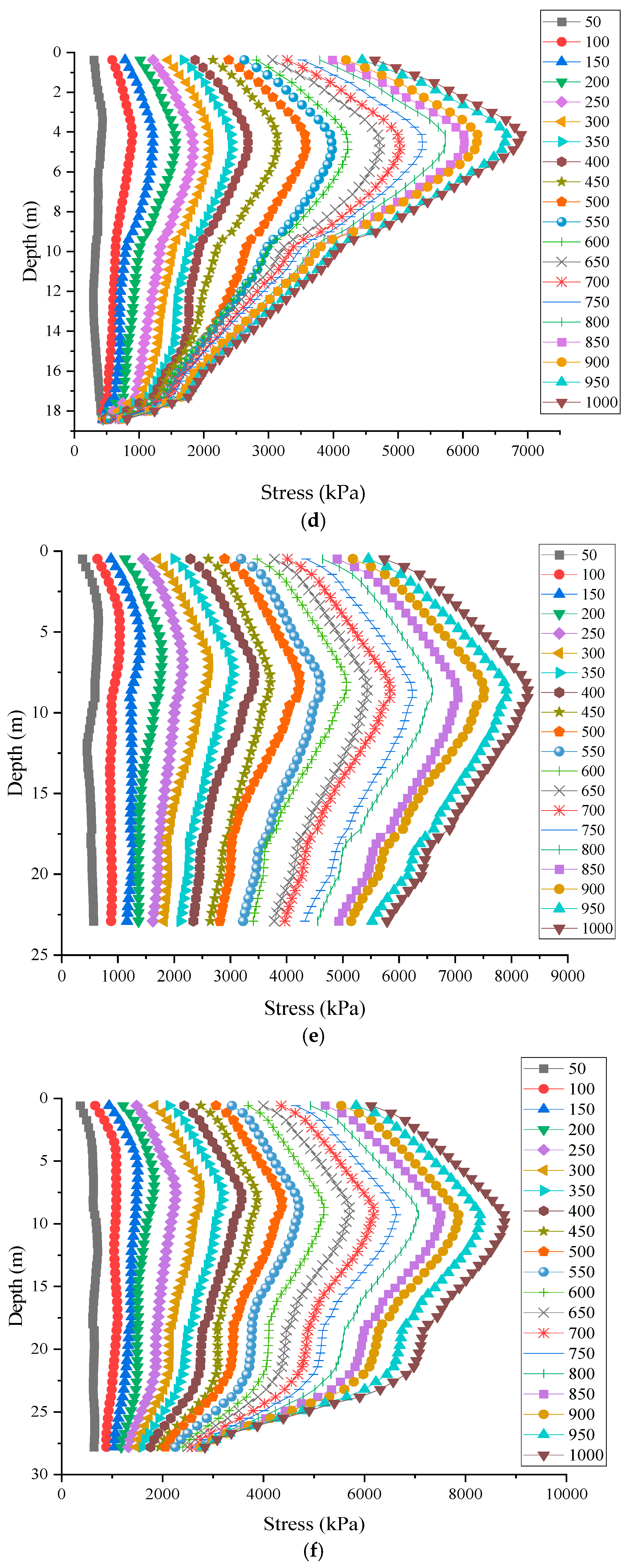
Based on the stress values of the central pile elements under load, and the stress values of the central pile elements after the completion of pile group construction, the axial stress of the central piles can be calculated. The distribution of axial stress under different loads and pile lengths is shown in
Figure 6. During the loading process, when the pile body is embedded in the strongly weathered sandy mudstone layer (28.4 m and 33.4 m), the axial stress of the pile first increases along the pile length, then gradually decreases, followed by a slow decrease over a certain length, and finally decreases rapidly. The minimum axial stress of the pile is at the pile tip, and the maximum axial stress is at a certain depth below the pile top. The overall trend is a “W” shape, similar to the change trend of single-pile composite foundations mentioned earlier. The “W” shape distribution of axial stress in piles can be explained by the load transfer mechanism along the pile shaft. Initially, as the load is applied, the pile head experiences the highest stress due to direct load application. As the load is transferred down the pile, the stress decreases due to the mobilization of soil resistance along the pile shaft. The stress reaches a minimum at the pile tip, where the load is transferred to the surrounding soil. For longer piles, the stress distribution is influenced by the interaction between the pile and the surrounding soil layers. The pile–soil interface friction and the soil’s shear strength play a crucial role in distributing the load along the pile length, resulting in the observed “W” shape stress distribution.
When the pile length is relatively short (23.4 m), the axial stress at the pile tip is generally higher. As the pile length decreases, the axial stress at the pile tip also increases. This is because a shorter pile length results in insufficient side frictional resistance to reduce the axial force of the pile body, leading to an increase in the axial stress at the pile tip. As the pile length increases, the axial stress at the pile tip decreases. This is due to the interaction effect of the pile group, which enhances the bearing capacity of the soil at the pile tip. For comparison, similar trends have been observed in studies by Zhang and Wei [
21], who analyzed the axial stress distribution in piles under various loading conditions. They found that the axial stress distribution in piles embedded in competent soil layers also exhibited a “W” shape, with the highest stress occurring at a certain depth below the pile top. This similarity suggests that the interaction between the pile and the surrounding soil, as well as the embedment depth, plays a crucial role in determining the axial stress distribution in pile foundations.
3.3. Pile–Soil Stress Ratio
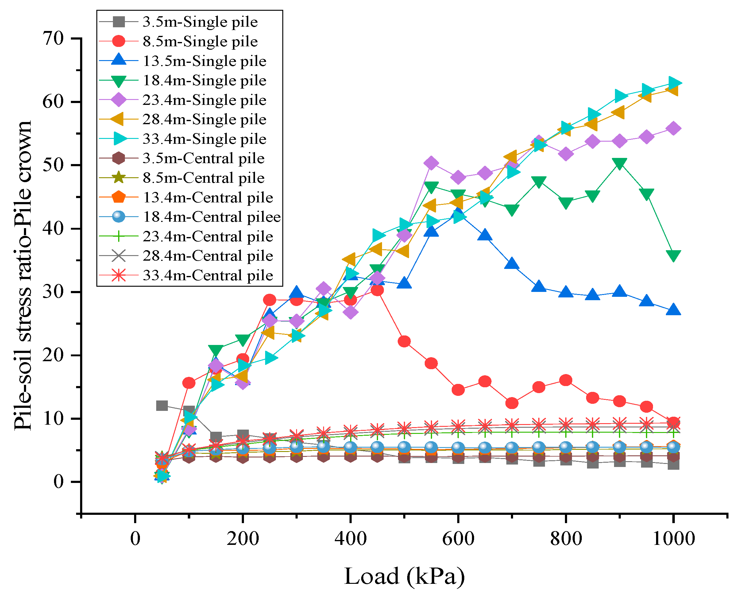
The relationship between the pile–soil stress ratio at the top of piles and the load for different pile lengths is shown in
Figure 7. For pile lengths of 3.5 m, 8.5 m, 13.4 m, and 18.4 m, as the load applied by the upper structure gradually increases, the pile–soil stress ratio at the pile top also increases. However, once the load reaches a threshold of 100 kPa, the rate of increase in the pile–soil stress ratio significantly slows down. This observation can be attributed to the fact that under these shorter pile lengths, the soil surrounding the piles reaches a state of near-saturation in terms of load-bearing capacity. As the load continues to increase beyond 100 kPa, the soil is unable to provide additional resistance, and the pile–soil stress ratio tends to stabilize. This indicates that the load-bearing potential of the pile itself is approaching its limit, and further increases in load do not significantly alter the stress distribution between the pile and the soil. The pile–soil stress ratio is a critical parameter that reflects the load-sharing behavior between the pile and the surrounding soil. For shorter piles, the soil surrounding the pile quickly reaches its load-bearing capacity, leading to a rapid increase in the pile–soil stress ratio. As the load continues to increase, the soil’s ability to provide additional resistance diminishes, resulting in a plateau in the stress ratio. In contrast, longer piles penetrate deeper into the soil, reaching more competent layers that can provide greater resistance. This deeper embedment allows for more effective load transfer from the pile to the soil, resulting in a higher load threshold before the stress ratio begins to plateau. The enhanced interaction between the pile and the surrounding soil layers, particularly in the deeper, more competent layers, contributes to the observed differences in the pile–soil stress ratio for different pile lengths.
For longer piles, such as those with lengths of 23.4 m, 28.4 m, and 33.4 m, the pile–soil stress ratio at the pile top also increases with the increase in the upper load, but the load threshold required to reach the slow growth stage is higher, reaching 600 kPa. This suggests that longer piles can withstand greater external loads and have better stress transfer performance because they penetrate through the weak soil layers and are embedded in the more robust strongly weathered sandy mudstone layer. This embedding not only increases the friction between the pile and the soil, but also enables the pile to better distribute the load, enhancing the stability of the entire composite foundation. It is recommended that, in actual construction, the pile tips should be embedded to a certain depth in the strongly weathered mudstone layer to ensure that the composite foundation can fully exert its load-bearing capacity.
3.4. Load-Bearing Area of Pile Group Composite Foundations
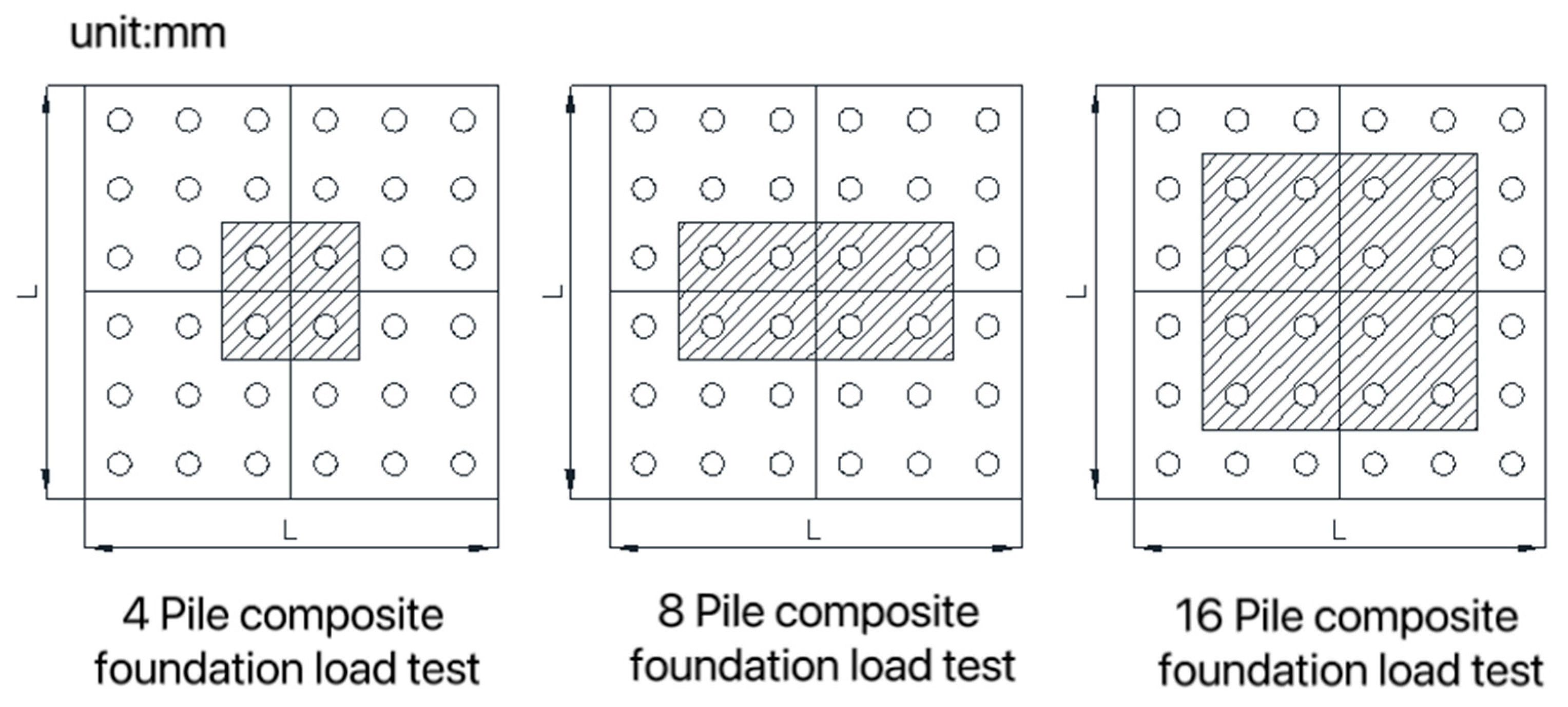
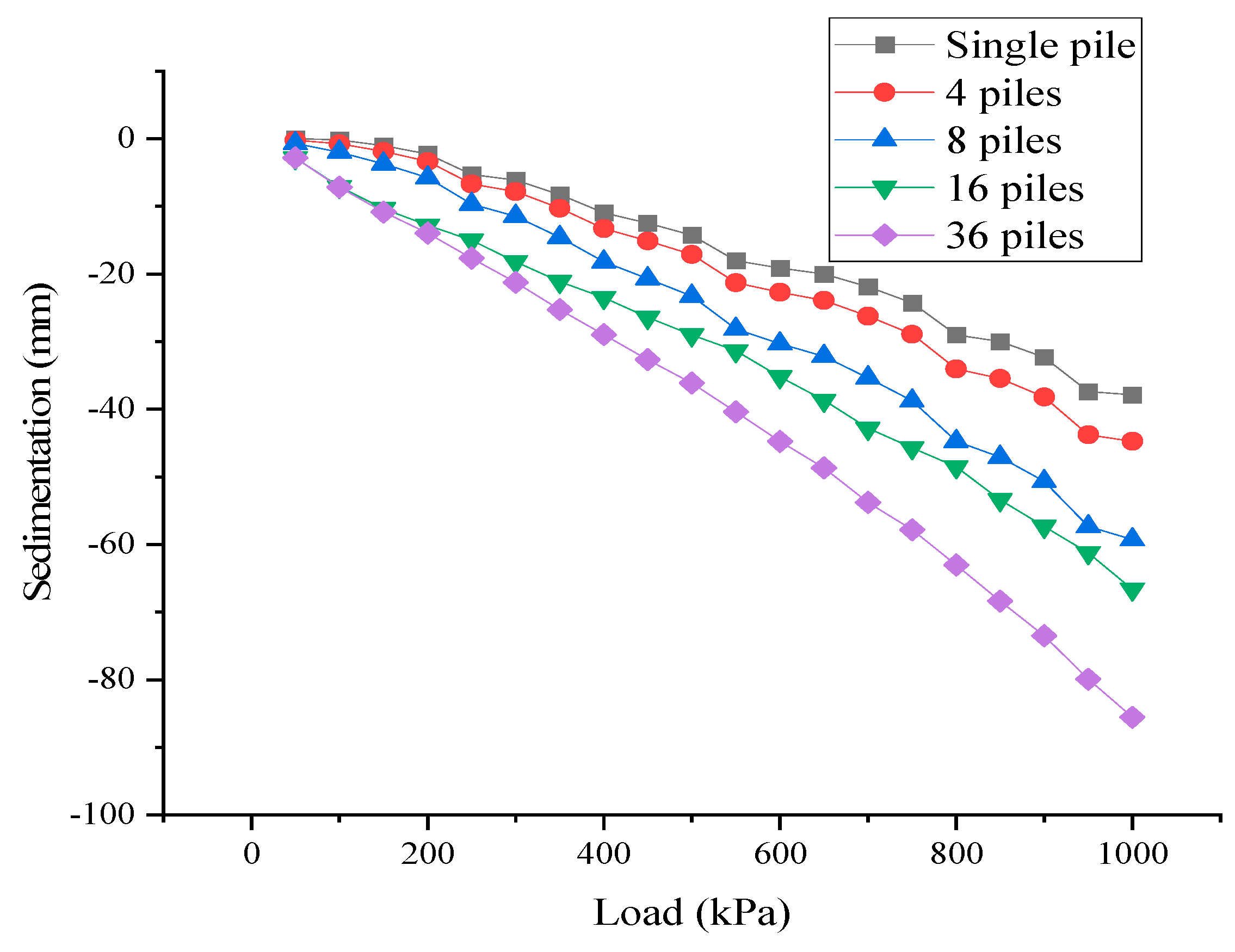
To obtain the load-bearing and deformation characteristics of multi-pile composite foundations, load tests were conducted on composite foundations with 4, 8, and 16 piles. The plan view of the test areas is shown in
Figure 8, with the shaded parts indicating the test areas. The load-settlement curves for different test areas are shown in
Figure 9. From the load test data, it can be seen that the bearing capacity of the composite foundations varied to different extents, regardless of whether they had 4, 8, or 16 piles. Although the strength of the soil between piles in the pile group composite foundation is higher than that of the soil surrounding single piles in a single-pile composite foundation, the overall bearing capacity of the composite foundation decreases as the number of piles increases. This indicates that in designing multi-pile composite foundations, not only should the load-bearing capacity of individual piles be considered, but so should the interactions between piles. Specifically, as the number of test piles increases, the settlement of the composite foundation under the same load conditions increases significantly. For example, the settlement of the 16-pile composite foundation under the same external load is much greater than that of the 8-pile composite foundation. This phenomenon suggests that when there are more piles, the stress distribution and compressibility of the soil between piles may lead to a reduction in the overall stiffness of the structure, thereby affecting the load-bearing performance of the foundation. For practical engineering applications, especially for critical buildings or cases with relatively small pile spacing, it is necessary to choose a multi-pile composite foundation test scheme. Such tests can not only more accurately assess the load-bearing capacity and deformation characteristics of the composite foundation, but also provide references for optimizing the design.
5. Conclusions
(1) The results demonstrate that increasing pile length significantly reduces the settlement of the raft foundation. When the pile length exceeds a critical value (23.4 m in this study), the interaction between piles and the surrounding soil is enhanced, leading to improved load-bearing capacity and reduced settlement. This finding underscores the importance of selecting an appropriate pile length to ensure the stability and performance of composite foundations.
(2) The axial stress distribution in piles embedded in strongly weathered sandy mudstone layers exhibits a “W” shape, with the highest stress occurring at a certain depth below the pile top. This stress distribution pattern is influenced by the pile length and the interaction between the pile and the surrounding soil. Longer piles tend to have a more uniform stress distribution, which contributes to better load transfer and reduced stress concentration at the pile tips.
(3) The pile–soil stress ratio at the pile top increases with the applied load but reaches a plateau at higher loads. For shorter piles, this plateau occurs at a lower load threshold (100 kPa), indicating that the load-bearing capacity of the soil is quickly saturated. In contrast, longer piles can withstand higher loads before reaching a similar plateau (600 kPa), highlighting their superior load transfer capabilities. This suggests that longer piles are more effective in utilizing the load-bearing capacity of the surrounding soil.
(4) The load-bearing capacity of composite foundations decreases as the number of piles increases, primarily due to the complex interactions between piles and the soil. This finding highlights the importance of considering not only the individual load-bearing capacity of piles, but also the group pile effect in the design of multi-pile composite foundations. This study also shows that the settlement of multi-pile composite foundations is significantly higher than that of single-pile foundations under the same load conditions, emphasizing the need for careful design and optimization.
(5) The results of this study provide valuable insights for the design and optimization of pile group composite foundations. Engineers should consider the critical pile length, pile spacing, and soil conditions to ensure optimal performance. The findings also suggest that embedding pile tips into stronger soil layers (such as strongly weathered sandy mudstone) can significantly enhance the stability and load-bearing capacity of composite foundations.


