Article

A Comparative Investigation on Axial and Flexural Performance of Circularized Square RC Columns with Discontinuous and Continuous CFRP Confinement

1
Construction Management Division, The University of Da Nang—University of Science and Technology, Da Nang 550000, Vietnam
2
Bridge and Underground Division, The University of Da Nang—University of Science and Technology, Da Nang 550000, Vietnam
3
Construction Informatics Division, The University of Da Nang—University of Science and Technology, Da Nang 550000, Vietnam
*
Author to whom correspondence should be addressed.
Buildings 2025, 15(8), 1228; https://doi.org/10.3390/buildings15081228
Submission received: 18 February 2025 / Revised: 27 March 2025 / Accepted: 2 April 2025 / Published: 9 April 2025
(This article belongs to the Section Building Structures)

Abstract

This paper aims to comprehensively investigate the axial and flexural performance of circularized square reinforced concrete (CSRC) columns discontinuously and continuously confined with carbon fiber-reinforced polymer (CFRP). The test results of twenty reinforced concrete (RC) columns, consisting of twelve CSRC columns and eight square RC (SRC) columns, are presented to compare the axial and flexural performance of discontinuously CFRP-confined CSRC (CFRPC-CSRC) columns with those of continuously CFRPC-CSRC and CFRPC-SRC columns. It was found that to enhance the load-bearing capacity (LBC) of SRC columns, circularizing the SRC columns before applying either discontinuous or continuous FRP confinement was more effective than applying continuous FRP confinement alone. Additionally, the theoretical strength interaction diagrams of test columns were developed using the strip-by-strip method, showing a strong agreement with the experimental results.

1. Introduction

Owing to their excellent mechanical properties and ease of construction, fiber-reinforced polymer (FRP) composites have been widely utilized to strengthen and upgrade existing reinforced concrete (RC) structures, particularly in enhancing the load-bearing capacity (LBC) and deformation (ductility) of RC columns [1,2,3]. The research topics on the confinement mechanism and performance of FRP-confined concrete have attracted great research interest over the last two decades [4], resulting in more than 200 experimental research studies [5], 80 stress–strain models of FRP-confined concrete [6,7,8,9] and a large number of numerical investigations [10,11,12]. The research outcomes have shown that concrete compressive strength [13,14], cross-sectional shape [15,16,17], axial compression eccentricity [18,19,20,21], fiber orientation [22], number of FRP plies [23], and FRP strengthening schemes [24,25,26,27] have significant effects on the behavior of FRP-confined concrete. It is also well established that the application of an external FRP confining system on RC columns significantly improves the LBC and deformation because the lateral confining pressure generated by FRP confining system inhibiting the lateral expansion of concrete core [28,29]. However, the LBC and deformation enhancement achieved in square RC columns is considerably lower than those achieved in circular RC columns [30,31]. This discrepancy arises from the non-uniform distribution of lateral confining pressure exerted by the external FRP confinement system [32,33,34,35]. Specifically, the pressure is highest at the corners and lowest along the flat sides of the concrete core [34,36].
Since square RC (SRC) columns are widely used in concrete structures (e.g., buildings and bridges), extensive investigations have been devoted to FRP-confined square concrete (FRPC-SC) columns (columns without steel reinforcement) [37,38] and FRP-confined SRC columns (columns with steel reinforcement) in an attempt to capture the behavior and predict the LBC and deformation [39,40]. However, most of the available investigations have been carried out on continuously FRPC-SC columns, while only a few have been concerned with discontinuously FRPC-SC columns [25,41]. Mai et al. [21,42] examined the effectiveness of discontinuous FRP confinement on SRC columns and reported a slight improvement in the LBC and significant enhancement in deformation. Additionally, Mai et al. [21] found that the improvement in the LBC due to discontinuous FRP confinement was much smaller than that achieved with continuous FRP confinement. Zeng et al. [43] evaluated the effectiveness of discontinuous FRP confinement on SC columns and observed a considerable enhancement in the LBC and significant improvement in the deformation. The finding of Zeng et al. [43] was also consistent with that of Mai et al. [21], confirming that the enhancement from discontinuous FRP confinement was notably lower than that from continuous FRP confinement.
Although discontinuous FRP confinement is less effective than continuous FRP confinement in enhancing the LBC of SC columns, the former offers several advantages over the latter. Discontinuous FRP confinement is constructed by bonding FRP rings along the column height with a clear spacing between two adjacent FRP rings [21,22], which helps to prevent the delamination between the FRP jacket and concrete core caused by air-voids [44,45]. Additionally, discontinuous FRP confinement is more cost-effective than continuous FRP confinement because it requires fewer FRP materials and adhesives [25,46,47]. Although discontinuous FRP confinement has high potential for strengthening SC columns, its effectiveness in improving the LBC of SC columns is still limited [48]. Therefore, several techniques have been proposed to improve the efficiency of discontinuous FRP confinement on SC columns. These techniques include rounding the sharp corners of SC columns [37,49], bonding additional FRP plies at the corners with the fibers parallel to the column axis [41], and modifying the SC columns to circular concrete columns [42,43]. These techniques are performed prior to the application of discontinuous FRP confinement to mitigate or eliminate the stress raiser at the corners of discontinuously FRPC-SC columns. Among these techniques, modifying the square cross-section to a circular one (hereafter referred to as cross-section modification) has been recognized as the most efficient approach for enhancing the efficiency of discontinuous FRP confinement. In practice, the cross-section modification can be performed either by attaching the pre-manufactured concrete segments into four flat sides of existing SC columns or by installing the circular formwork on the existing SC columns before casting concrete (self-compacting concrete or normal concrete) to obtain circular cross-section. Although there are several advantages of changing the cross-section, this technique also has some disadvantages, including (1) the increase in the dead-load applied on the foundation; (2) the increase in the labor cost due to the complexity in circularizing the square cross-section; and (3) the reduction in the clear and usable space of repaired structures due to a larger column cross-section. Due to the reduction in usable space after applying the cross-section modification, this technique can be used for upgrading the bridge pillars and marine columns as well as underground columns of the buildings.
Zeng et al. [43] examined the efficiency of the cross-section modification technique in enhancing the LBC of SC columns by comparing the performance of discontinuously CFRP-confined circularized SC (CSC) columns with both discontinuously and continuously CFRP-confined SC columns under concentric axial compression. Their findings indicated that the cross-section modification significantly improved the confinement effectiveness of discontinuous FRP confinement, leading to a notable enhancement in the compressive strength and ultimate axial strain of CFRPC-SC columns [43]. Zeng et al. [43] also emphasized that, under concentric axial compression, the combined cross-section modification and discontinuous FRP confinement resulted in higher compressive strength and ultimate axial strain in the SC column compared to continuous FRP confinement alone. It should be noted that Zeng, et al. [43] had not yet compared the performance of discontinuously CFRPC-CSC columns to that of continuously CFRPC-SC under eccentric axial compression. In real-world structures, the RC columns are likely to be subjected to eccentric axial compression resulting from their positions in the structures (e.g., columns at the corners), imperfection of column material and geometry, and construction errors. Moreover, no research has evaluated the performance of discontinuously FRPC-CSRC columns as compared with continuously FRPC-SRC columns under either concentric or eccentric axial compression.
Building on the preceding discussion, this study aims to comprehensively compare the axial and flexural performance of CSRC discontinuously confined with CFRP to those of CSRC continuously confined with different plies of CFRP and to the axial and flexural performance of SRC continuously confined with the same plies of CFRP. The main parameters examined in this study consisted of different confining schemes (discontinuous and continuous FRP confinement), number of CFRP plies, different strengthening methods (continuous FRP confinement, the combined cross-sectional modification and continuous FRP confinement, the combined cross-sectional modification and discontinuous FRP confinement) and different loading conditions (concentric and eccentric axial compression as well as four-point flexural loading). It is worth mentioning that this is the first investigation comparing the performance of CFRPC-SCRC columns with discontinuous FRP confinement to their counterparts with continuous FRP confinement having an equivalent amount of CFRP used. This comparative investigation is expected to provide an insight into the effectiveness of the combined cross-section modification and discontinuous FRP confinement, the combined cross-section modification and continuous FRP confinement alone in strengthening SRC columns. Thus, the findings of this paper are expected to assist design engineers in selecting an optimal and cost-effective strengthening solution for practical SRC columns.

2. Experimental Program
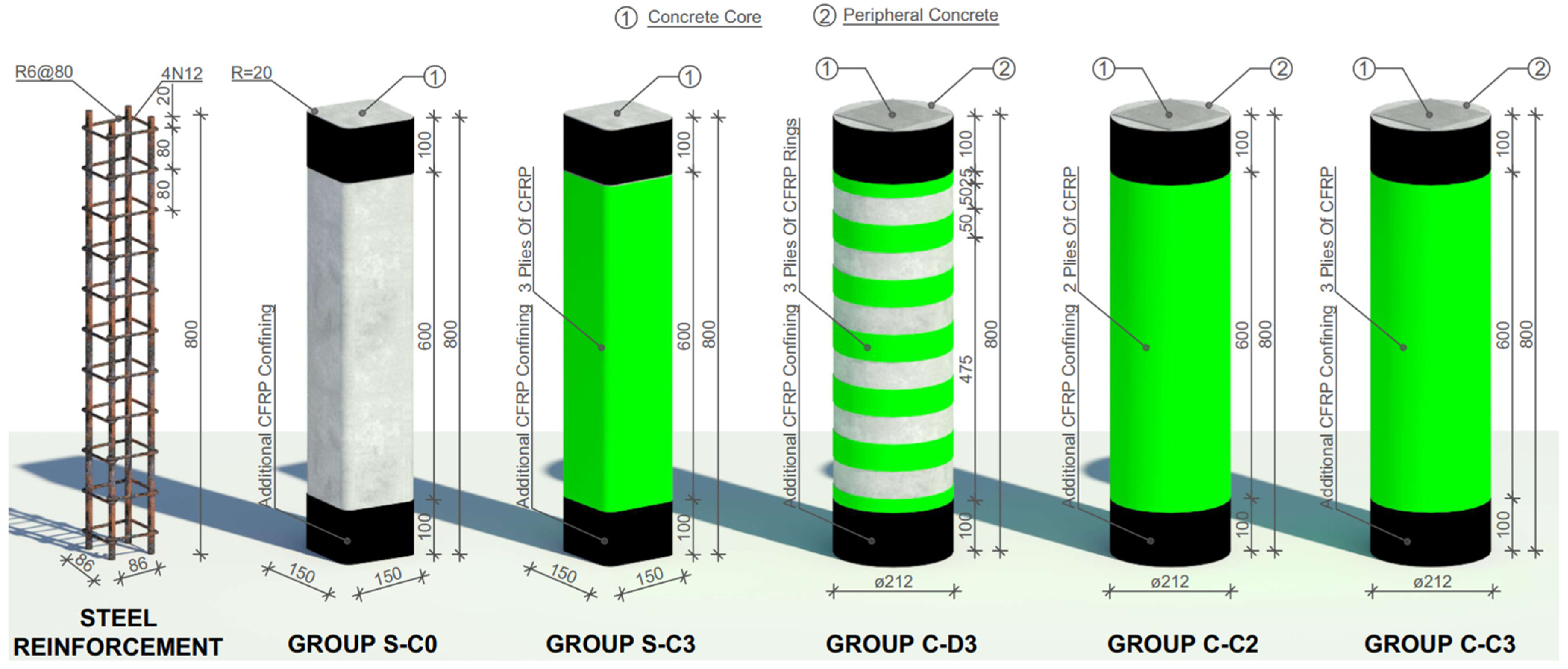
2.1. Test Specimens

A total of twenty RC specimens, consisting of eight SRC and twelve CSRC specimens, which were considered as columns, were categorized into five groups of four identical columns and tested under different loading conditions, as illustrated in Figure 1. As shown in Figure 1, each RC column was longitudinally reinforced by four deformed steel bars with 12 mm diameter (4N12), held in place by ten plain steel bars with 6 mm diameter (10R6), spaced at 80 mm center-to-center, serving as transverse reinforcement. The longitudinal and transverse reinforcement of the test specimens were chosen to represent the deficient RC columns based on the available research investigations [50,51,52]. Each set of four identical columns was subjected to four types of loading including concentric, 15 mm and 25 mm eccentric axial compression and four-point flexural loading.
Eight SRC columns with 800 mm in length, 150 mm in side length and 20 mm in corner radius were utilized to form the first and second groups in which the first group (Group S-C0) had no external FRP confinement, served as the reference group, while the second group (Group S-C3) was externally and continuously confined with three CFRP plies. Twelve CSRC columns with 800 mm height and 212 mm diameter were employed to form the remaining three groups (the third to fifth groups) in which the third group (Group C-D3) were externally and discontinuously confined with CFRP rings having a ring width of 50 mm, a clear spacing between two adjacent CFRP rings of 50 mm and three CFRP plies while the fourth and fifth groups were externally and continuously confined with two and three CFRP plies, respectively. The CFRP ring width of Group C-D3 was chosen to be equal to the clear spacing between two adjacent CFRP rings as commonly applied in previous studies [41,52,53,54]. To ensure the confinement effectiveness of discontinuous confinement in Group C-D3, the center-to-center distance of two adjacent CFRP rings was smaller than a half of the minimum cross-section of the column, as suggested in CNR-DT 200 R1/2013 [55]. It should be mentioned that these five groups of columns have been presented separately in different studies [21,42,56] undertaken by the first author of this study. In this paper, these five groups were assembled for the first time to comprehensively examine the effectiveness of the combined cross-section modification and discontinuous FRP confinement, aiming to establish an optimal strengthening method for SRC columns using an external FRP confining system.
As presented in Table 1, the column labeling system consists of three components separated by a dash, in which the first component stands for the cross-sectional shape (S for square and C for circular), the second component denotes the type of confining system (D for discontinuous confinement and C for continuous confinement) along with the number of CFRP plies, and the third component indicates the types of loading (E0 for concentric axial compression; E15 and E25 for 15 mm and 25 mm eccentric axial compression, respectively; and F for four-point flexural loading). For instance, Column C-C2-E15 represents a CSRC column with a circular cross-sectional shape continuously confined with two CFRP plies and subjected to 15 mm eccentric axial compression.

2.2. Specimen Preparation and Preliminary Testing

The SRC columns of Groups S-C0 and S-C3 were manufactured by casting concrete in plywood formwork assembled by fixing the four pieces of Styrofoam with a 20 mm radius into the four corners of the formwork to create four rounded edges for SRC columns. The CSRC columns of Groups C-D3, C-C2 and C-C3 were produced by bonding four peripheral concrete into four flat sides of base SRC columns (columns without corner radius) using a bonding agent composed of silica microsphere, epoxy resin and slow hardener in a 10:5:1 ratio. The peripheral concrete was cast using a formwork, which was established by placing Polyvinyl chloride pipes (PVC) with 800 mm in height and 212 mm in inner diameter outside the Styrofoam prism with 800 mm in height and 150 × 150 mm in cross-section.
The columns of Groups S-C3, C-D3, C-C2 and C-C3 were externally bonded with CFRP rings or sheets using the wet layup process in which the CFRP fibers were oriented perpendicular to the column axis. The bonding agent for bonding CFRP comprised a slow hardener and an epoxy resin in a 1:5 ratio. A 100 mm overlap was applied for external CFRP ply to ensure sufficient bonding while two additional CFRP plies with 100 mm width were applied at columns’ two ends to prevent premature failure (crushing of concrete at the two ends) at the stress concentration points.
The preliminary tests were performed to determine the mechanical properties of constitutive materials (i.e., concrete, longitudinal and transverse steel bars, and CFRP). Ready-mix normal strength concrete from local concrete company was used to cast the columns. The 28th-day concrete compressive strength ( f c o ) was measured by testing three 200 × 100 mm (height × diameter) concrete cylinders in accordance with AS 1012.9:2014 [57] and found to be 36 MPa. The tensile properties of steel and CFRP were measured by testing three samples of each material in accordance with AS 1391-2007 [58] and ASTM D3039/D3039M-14 [59], respectively, which were presented in Table 2 and Table 3. The testing samples of steel had a length of 500 mm while the testing samples of CFRP had a width of 22.75 mm and a length of 250 mm.

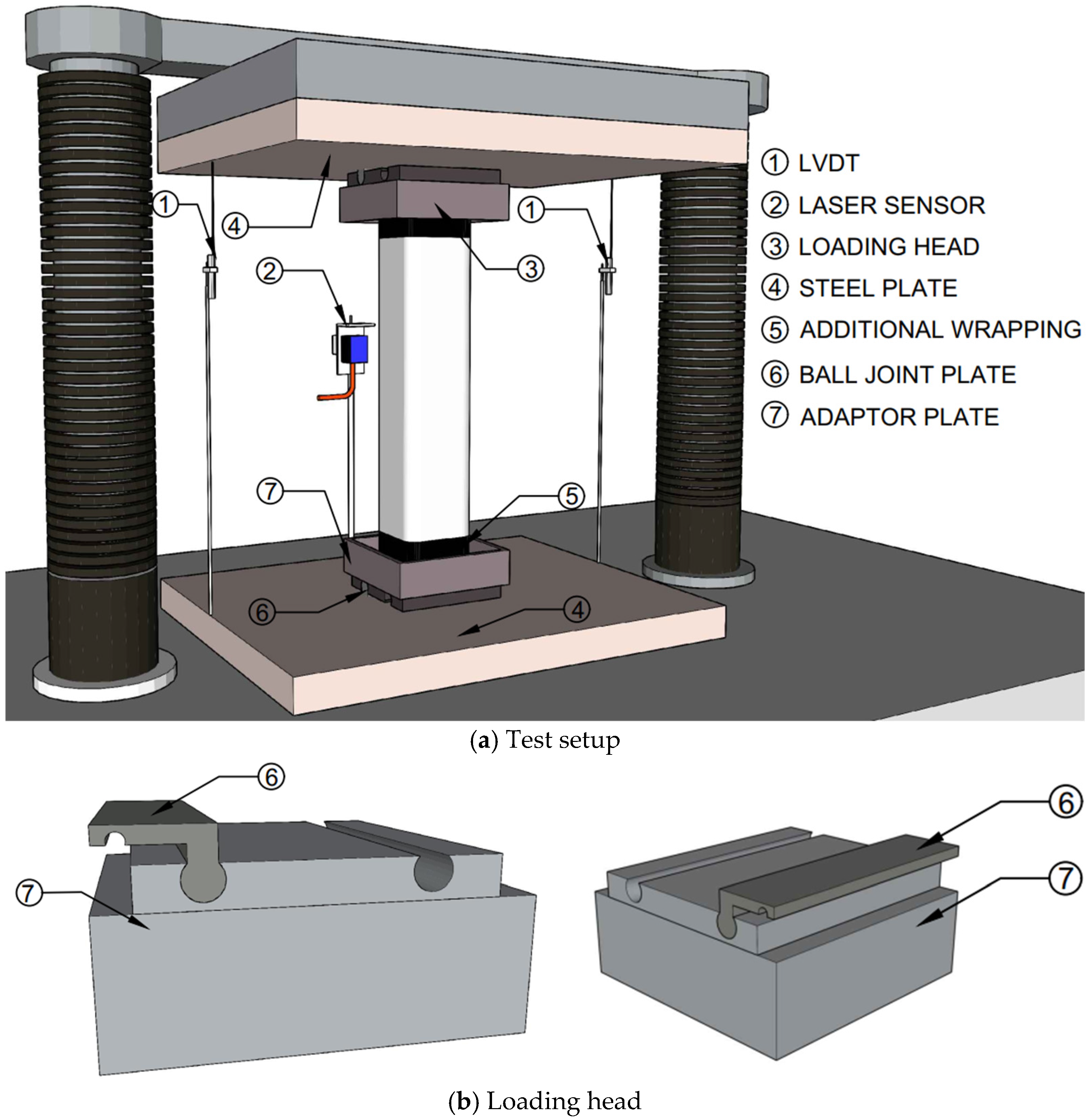
2.3. Test Setup and Instrumentation

The columns were tested by the Avery 500 Tonne Compression Test Machine (Fairmont, MN, USA). For preventing the movement of columns during the test, a preload of up to 200 kN was applied on the columns and then reduced to 20 kN under a force-controlled load of 2 kN/s. The columns were then tested until failure using a displacement-controlled load at a rate of 0.3 mm/min.
The concentric and eccentric axial compression loads were generated by two loading heads attached to the two ends of the vertical columns, while the four-point flexural loading was induced by two steel rigs positioned above and under the beams (columns tested as beams). The loading head had two parts consisting of an adaptor plate and a ball joint plate. The adaptor plate was directly attached to the column while the ball joint plate was connected to the adaptor plate to generate eccentricity, as shown in Figure 2. For columns under concentric axial compression, only the adaptor plate was used. For generating four-point flexural loading, the top steel rigs placed above the beams had a clear span of 233 mm while the bottom steel rigs placed under the beams had a clear span of 700 mm. The detailed descriptions of equipment used to generate axial compression and flexural loadings can be found in Hadi and Widiarsa [60]. For a uniform distribution of the axial compressive load, both ends of the vertical columns were capped by high-strength plaster. The testing machine was equipped with two linear variable differential transducers (LVDTs, positioned 1800 apart from each other) and a laser sensor for, respectively, capturing the column’s axial and lateral deformation. The LVDTs and a laser sensor were connected to a data logger to record the test data every two seconds.

3. Experimental Results and Discussion

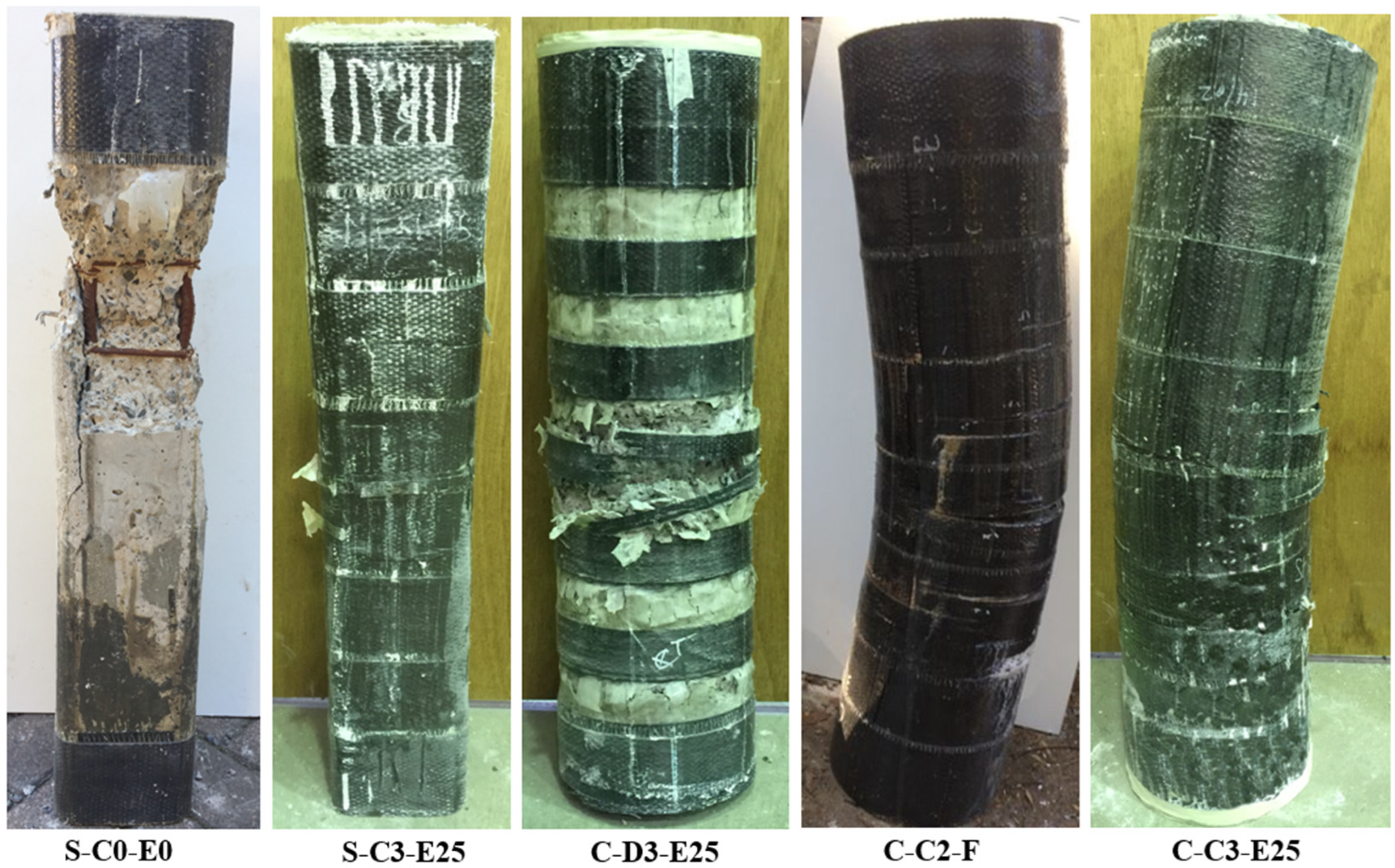
3.1. Failure Patterns

The typical failure patterns of the columns are presented in Figure 3. Under concentric axial compression, the columns exhibited brittle failures in which the reference column (Column S-C0-E0) failed due to the concrete cover loss, whereas the FRP-confined columns (Columns S-C3-E0, C-D3-E0, C-C2-E0 and C-C3-E0) failed due to CFRP rupture. Because of the sudden CFRP rupture, the FRP-confined columns’ failures were significantly more explosive than the reference column’s failure. The CFRP rupture on Column S-C3-E0 suddenly occurred at one of the column corners, which is similar to the failure pattern of continuously FRPC-SRC column in Hadi and Widiarsa [60], while the CFRP ring rupture on Column C-D3-E0 happened after the column experienced concrete cover cracking at the non-confined region. The CFRP ruptures on Columns C-C2-E0 and C-C3-E0 were at or in the vicinity of the columns’ mid-height. The failure mode of C-D3-E0 was in agreement with the failure mode of discontinuously FRP-confined circular concrete columns investigated by Zeng et al. [46] and Wang et al. [47] while the failure patterns of Columns C-C2-E0 and C-C3-E0 were consistent with the failure patterns of continuously FFRP-confined circular RC columns in previous studies [16,61].
Under eccentric axial compression, the reference columns failed due to the concrete cover crushing, followed by the longitudinal reinforcement buckling on the compression face. In contrast, the failures of the CFRP-confined RC columns were controlled by the CFRP ruptures, followed by the longitudinal reinforcement buckling on the compression face. In Group C-D3, the concrete cover crushing was observed at the non-confined region on the compression face before the CFRP ring rupture. Meanwhile, in Groups S-C3, C-C2 and C-C3, the horizontal concrete crack was first observed on the tension face, followed by the sudden CFRP rupture on the compression face.
The columns under four-point flexural loading exhibited a similar failure pattern, where the failures were initiated with a concrete hairline vertical crack on the tension face and were ultimately governed by the longitudinal reinforcement fracture on the tension face. At failure, concrete crushing was observed on the compression face in all test columns.

3.2. Load-Deformation Responses of Test Columns

The key test results of the columns under axial compression were summarized in Table 4, while the key test results under flexural loading were reported in Table 5. The key test results include the yield axial load and corresponding axial deformation ( P y , y ), the yield flexural load and corresponding mid-span deflection ( P y , δ y ), the ultimate axial load and corresponding axial and lateral deformation ( P u l t , p , δ p ), the ultimate flexural load and corresponding mid-span deflection ( P u l t , δ p ), the ultimate axial deformation, ( u l t , axial deformation after the P u l t at 0.85 P u l t ), the ultimate mid-span deflection ( δ u l t ) and the ductility ( μ ), which is defined as the ratio between the u l t and y for columns under axial compression and the ratio between the δ u l t and δ y for columns under flexural loading.

3.2.1. Behavior of Columns Under Concentric Axial Compression

The axial load–axial deformation ( P - ) responses of the columns under the concentric axial compression are plotted in Figure 4a. Initially, the P - responses exhibited linear ascending responses, followed by post-peak ascending responses in CFRP-confined columns and a post-peak descending response in the reference column. The difference between the post-peak responses of CFRP-confined columns and that of the reference column was attributed to the activation of CFRP after the concrete cracking. It is reported that the CFRP was effectively activated when the axial load reached about 87% of the P u l t of the reference column.
As shown in Figure 4a, columns with the same cross-sectional shape exhibited a similar initial linear P - response; however, the slopes of the initial linear P - responses were higher in the circular columns compared to the square columns. The stiffer initial linear P - responses of Columns C-D3-E0, C-C2-E0 and C-C3-E0 relative to those of Columns S-C0-E0 and S-C3-E0 indicate that the CSRC columns had a higher stiffness than the SRC columns. This difference is attributed to the greater cross-sectional area of CSRC columns compared to SRC columns. The stiffer initial linear P - response of CSRC column compared to that of SRC column was also observed by Hadi et al. [62].
Following the initial linear P - responses, Columns S-C3-E0, C-D3-E0, C-C2-E0 and C-C3-E0 exhibited a substantial increase in the axial load beyond the yield point, reaching the P u l t at the CFRP rupture. In contrast, Column S-C0-E0 underwent a slight increase in the axial load, followed by an abrupt drop because of the concrete cover loss. As shown in Figure 4a, the post-peak ascending gradients of Columns C-D3-E0, C-C2-E0 and C-C3-E0 were higher than that of Column S-C3-E0, indicating that the FRP confinement was more effective in CSRC columns than in SRC columns. Among CFRPC-CSRC columns, Column C-C3-E0 exhibited the highest post-peak ascending gradient, followed by Columns C-C2-E0 and C-D3-E0, respectively. Consequently, Column C-C3-E0 attained the highest P u l t , followed in descending order by Columns C-C2-E0, C-D3-E0, S-C3-E0 and S-C0-E0.
As summarized in Table 4, CFRP-confined columns achieved a substantial enhancement in the axial load compared to the reference column. The P u l t of Columns S-C3-E0, C-D3-E0, C-C2-E0 and C-C3-E0 were substantially greater (62.5%, 128.3% and 195.9%, respectively) than the P u l t of Column S-C0-E0. Among the CFRP-confined columns, Column S-C3-E0 obtained the smallest P u l t (1614.5 kN), which was 40.5%, 60% and 82.1% less than the P u l t of Columns C-D3-E0 (2268.5 kN), C-C2-E0 (2534.1 kN) and C-C3-E0 (2939.7 kN), respectively. It should be mentioned that the amount of CFRP used for Column S-C3-E0 (1,437,592 mm2) was 24.5%, 25.4% higher than those used for Columns C-D3-E0 (1,154,614 mm2) and C-C2-E0 (1,146,292 mm2), respectively. The smaller P u l t of Column S-C3-E0 relative to the P u l t of Columns C-D3-E0 and C-C2-E0, while the greater amount of CFRP used for Column S-C3-E0 relative to that of Columns C-D3-E0 and C-C2-E0 indicated that the combined cross-section modification and FRP confinement was significantly more effective in improving the LBC of the SRC column compared to FRP confinement alone. Interestingly, although Column C-D3-E0 utilized a 7% greater amount of CFRP than Column C-C2-E0, its P u l t was 11.7% lower than that of Column C-C2-E0.
As shown in Figure 4a and Table 4, the u l t of Column S-C3-E0 was considerably higher than the u l t of Columns C-C3-E0, C-C2-E0 and C-D3-E0 and the reference column. Consequently, Column S-C3-E0 obtained the highest μ , followed by Columns C-C3-E0, C-C2-E0, C-D3-E0 and S-C0-E0, respectively.

3.2.2. Behavior of Columns Under Eccentric Axial Compression

The P - responses of the columns under eccentric axial compression are plotted in Figure 4b,c. Similarly to the P - responses of the columns under concentric axial compression, the P - responses of the columns under eccentric axial compression began with linear P - responses and then followed by post-peak ascending responses in the CFRP-confined columns and post-peak descending responses in the reference columns. The variation in the post-peak responses was due to the activation of CFRP confinement after concrete cracking on the compression face. As shown in Figure 4b,c and summarized in Table 4, for the same value of eccentricity ( e ), the P u l t of the columns of Group C-C3 was highest, followed in descending order by the P u l t of the columns of Groups C-C2, C-D3, S-C3 and S-C0. Notably, despite using less CFRP than the columns of Group S-C3, the columns of Groups C-D3, C-C2 and C-C3 attained higher P u l t than the columns of Group S-C3. Specifically, the P u l t of Columns C-D3-E15, C-C2-E15 and C-C3-E15 were 65.8%, 72.8% and 97.2%, respectively, higher than the P u l t of Column S-C3-E15. Similarly, the P u l t of Columns C-D3-E25, C-C2-E25 and C-C3-E25 were 69.7%, 75.8% and 85.4%, respectively, higher than the P u l t of Column S-C3-E25. These results indicate that the combination of the cross-section modification and FRP confinement was more effective in enhancing the LBC of the SRC columns than the application of FRP confinement alone. Additionally, it is noteworthy that although the amount of CFRP used for the columns of Group C-C2 was 11.7% less than that used for the columns of Group C-D3, the P u l t of the columns of Group C-C2 was slightly higher than that of the columns of Group C-D3. Specifically, the P u l t of Columns C-C2-E15 and C-C2-E25 were 4.2% and 3.6% higher than the P u l t of Columns C-D3-E15 and C-D3-E25, respectively. As illustrated in Table 4, for the same eccentricity, although the u l t of the columns of Group S-C3 was smaller than the u l t of the columns of Groups C-D3, C-C2 and C-C3, the μ of the columns of Group S-C3 was higher than that of the columns of Groups C-D3, C-C2 and C-C3.

3.2.3. Behavior of Columns Under Flexural Loading

The flexural load-midspan deflection ( P - ) responses of the columns under flexural loading are presented in Figure 4d. The P - response of Column S-C0-F began with an initial ascending response, followed by a plateau due to the longitudinal reinforcement yield. It should be noted that Column S-C0-F slipped at one of the supports when the P u l t was obtained, which may contribute to the plateau of the P - response. Similarly, the P - responses of Columns C-D3-E25, C-C2-E25 and C-C3-E25 exhibited initial ascending responses, but unlike Column S-C0-F, they were followed by post-peak ascending responses before reaching the P u l t . This post-peak increase was because of the CFRP confinement effect on the compression face. Among the test columns, Column C-C3-F attained the highest P u l t , followed in descending order by Columns C-C2-F, C-D3-F, S-C3-F and S-C0-F. In contrast to the P u l t , the highest μ was achieved by Column S-C0-F, followed by the μ of Columns S-C3-F, C-D3-F, C-C3-F and C-C2-F, as illustrated in Table 5.

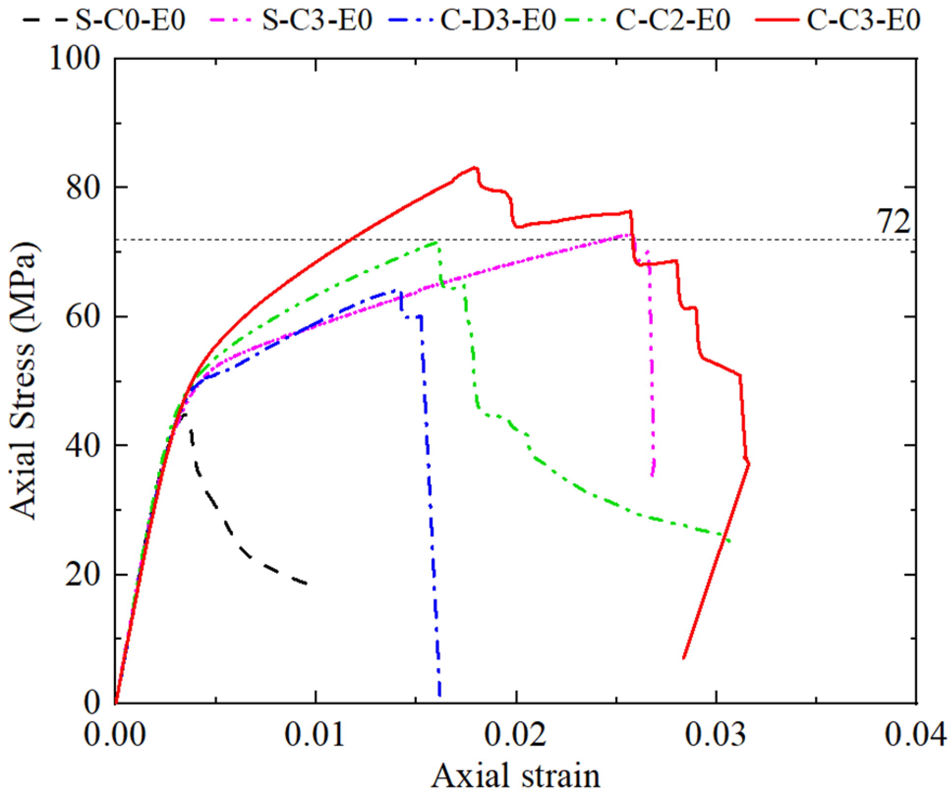
3.3. Axial Stress-Axial Strain Response

As shown in Table 4, the P u l t of Columns C-D3-E0, C-C2-E0 and C-C3-E0 was significantly higher than the P u l t of Column S-C3-E0. This was because the CFRPC-CSRC columns benefitted from a higher level of CFRP confinement and a greater cross-sectional area than the CFRPC-SRC columns. Thus, to evaluate the contribution of the cross-section modification in enhancing the LBC of the SRC column, the axial stress–axial strain ( σ - ε ) responses of columns under concentric axial compression were plotted, as illustrated in Figure 5. As revealed in Figure 5, the ultimate axial stress of Column C-D3-E0 was lower than that of Column S-C3-E0, demonstrating that the discontinuous FRP confinement effect on the CSRC column was lower than the continuous FRP confinement effect in the SRC column. This was due to the presence of non-confined regions in discontinuously CFRPC-CSRC. The ultimate axial stress of Column S-C3-E0 was lower than that of Column C-D3-E0, which shows that the cross-section modification significantly enhanced the CFRP confinement level. Interestingly, although a smaller number and amount of CFRP plies used for Column C-C2-E0 relative to Column S-C3-E0, the ultimate axial stress of Column C-C2-E0 was equivalent to that of Column S-C3-E0.

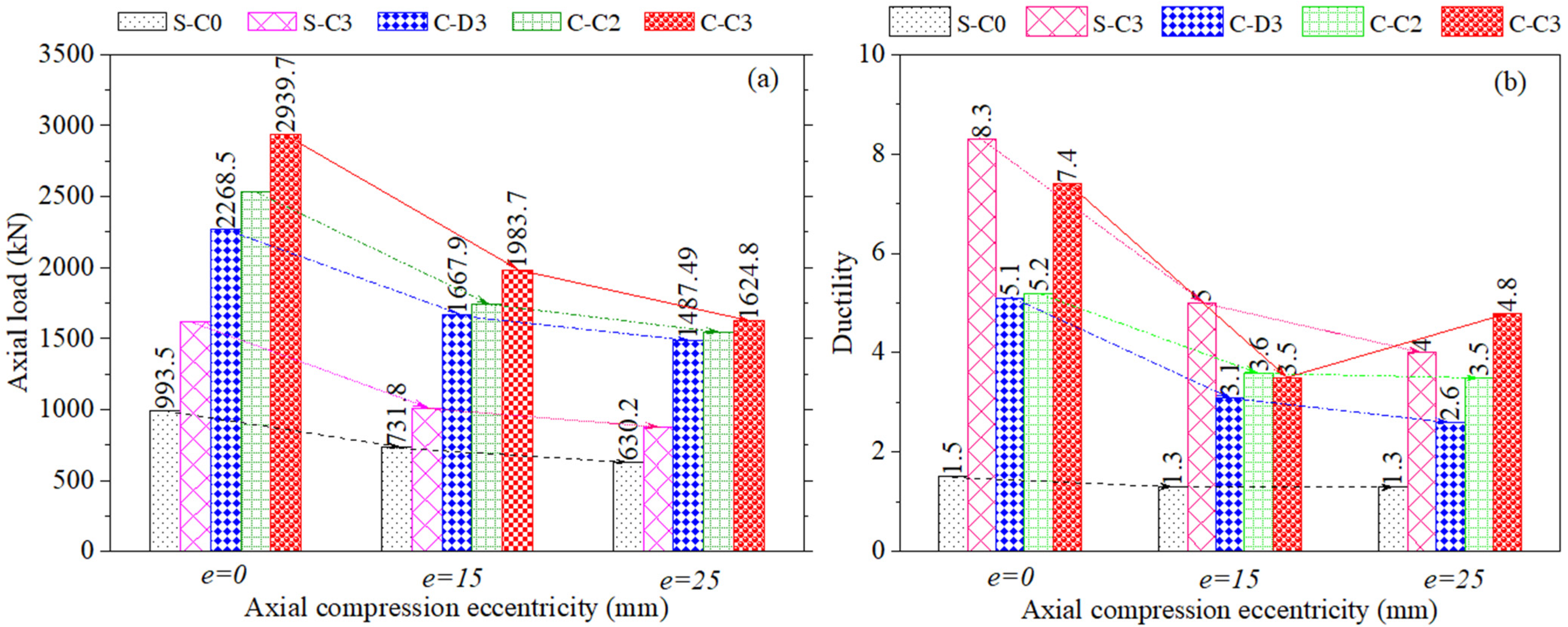
3.4. Effect of Axial Compression Eccentricity ( e )

Figure 6 illustrates the influence of e on the P u l t and μ of the test columns. As shown in Figure 6, increasing the value of e led to a substantial reduction in the P u l t , as a larger value of e corresponds to a smaller compressive area of concrete confined by CFRP. Among the test columns, the most significant reduction in the P u l t was observed in Groups C-C3 and S-C3, while Groups C-D3 and S-C0 exhibited the smallest reduction in the P u l t . In terms of ductility, except Groups C-C3 and S-C0, increasing the value of e resulted in a substantial decline in the μ . The most pronounced reduction in the μ occurred in Groups S-C3 and C-D3, whereas Group S-C0 experienced the smallest decrease in the P u l t as the e increased.

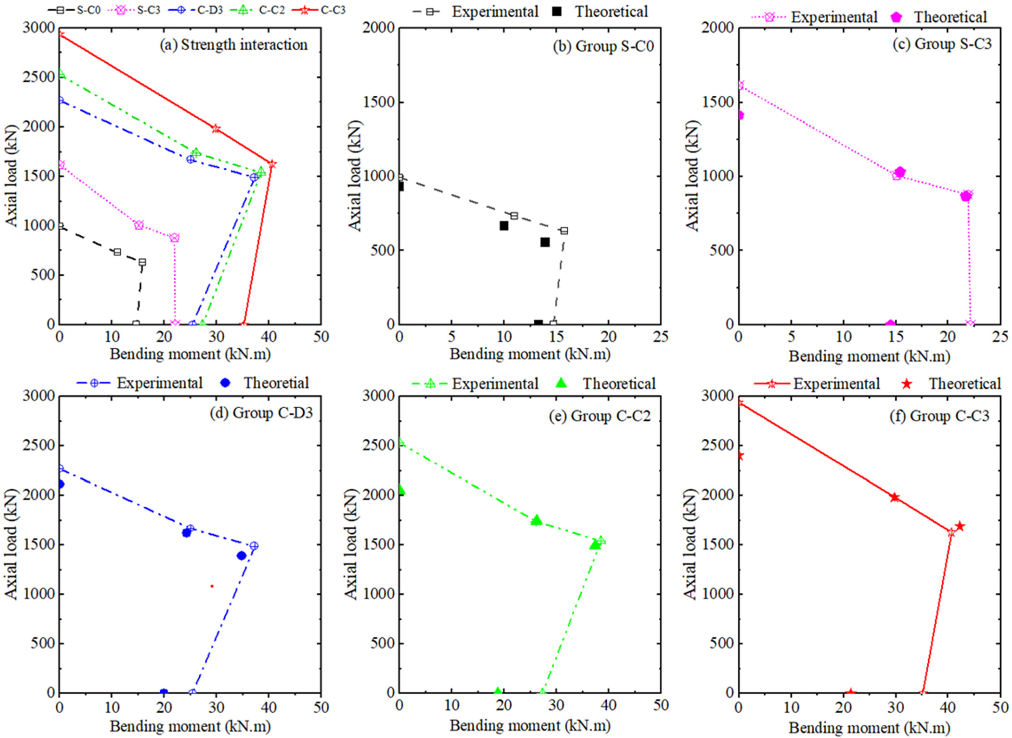
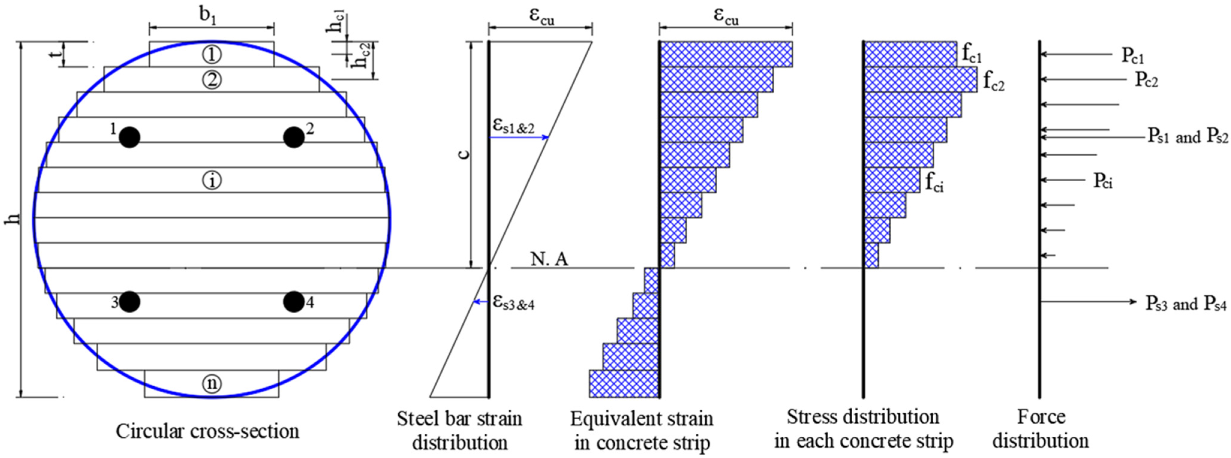
4. Strength Interaction Diagrams

The experimental strength interaction diagrams were established based on four data points, corresponding to four types of loading used in column testing to examine the axial and flexural capacity of the test columns. The columns’ bending moment under axial compression and flexural loading were given by Equations (1) and (2), respectively.
M u = P u l t e
M u = 1 2 P u l t a
where a = length of shear span, which was taken as 230 mm.
The columns’ experimental strength diagrams were plotted in Figure 7a, while the experimental P u l t and corresponding M u were summarized in Table 6. As shown in Figure 7a and Table 6, the highest strength diagram was obtained by Group C-C3 columns, followed by the strength diagrams of Groups C-C2, C-D3, S-C3 and S-C0 columns. For the same amount of CFRP used, the strength diagram of Group C-C2 was slightly smaller than that of Group C-D3. Notably, the strength diagram of Group C-C2 columns was significantly higher than that of Group S-C3 columns, revealing that, for improving the LBC of SRC columns, modifying the cross-section before applying either discontinuous or continuous FRP confinement was far more effective than applying continuous FRP confinement alone.
The columns’ analytical strength diagrams were established using the strip-by-strip method, in which the column cross-sections were divided into finite small horizontal strips, each with a unit height of 1 mm. As shown graphically in Figure 8, by assuming a plain section and a value of neutral axis depth ( c ), the strain of each strip ( ε c i ) was found using the principle of similar triangles [Equation (3)], while the corresponding stress ( σ c ) was determined using the stress–strain relationship. Once the stress was determined, the compressive force ( P c i ) and bending moment ( M c i ) of each strip can be found using Equations (5) and (6), respectively. Next, the P u l t and M u of the columns were determined by summing the P i and M i of constituent materials over the column cross-section, as given in Equations (9) and (10), respectively.
ε c i = ε c u c h c i c
h c i = t i 1 2
P c i = σ c i b c i t
M c i = P c i h 2 i 1 2 t
ε s i = ε c u c h s i c
P s i = f s i A s i
M s i = P s i h 2 h s i
P u l t = P c i + P s i
M u = M c i + M s i
e = M n P n
The stress and strain relationship of steel reinforcement was correlated using a linear elastic-perfectly elastic model. For unconfined concrete of Group S-C0 columns, the stress- strain response was captured by using the Popovics [63] stress–strain model, while the stress–strain response of FRP-confined concrete in Groups C-C3, C-C2, C-D3 and S-C3 was simulated using the Lam and Teng [64] stress–strain model. The stress–strain model proposed by Lam and Teng [64] has been recognized as one of the most accurate models for FRP-confined concrete [6] and adopted in available design code for concrete structures strengthened by externally bonded FRP system of ACI 440.2R-17 [65].
In the unconfined stress–strain model proposed by Popovics [63], for a given axial strain ( ε c ), the unconfined concrete axial stress ( σ c ) can be found as below:
σ c = f c o ε c / ε c o n n 1 + ε c / ε c o n
ε c o = 0.000937 f c o 4
n = E c E c E s e c
E c = 4700 f c o   ( i n   M P a )
E s e c = f c o / ε c o   ( i n   M P a )
where f c o and ε c o , respectively, stand for the unconfined concrete compressive strength and axial strain at f c o ; E s e c and E c , respectively, stand for the unconfined concrete secant and elastic moduli.
In the FRP-confined concrete stress–strain model developed by Lam and Teng [64], for a given axial strain ( ε c ) , the axial stress ( σ c ) of FRP-confined concrete was given as below:
σ c = E c ε c E c E 2 2 4 f c o ε c 2 for   0   ε c ε t f c o + E 2 ε c for   ε t   ε c ε c u
ε t = 2 f c o E c E 2
E 2 = f c c f c o ε c u
where f c c and ε c u , respectively, stand for the FRP-confined concrete compressive strength and the ultimate strain, which were determined as below:
f c c = f c o + 3.3 k a f l
ε c u = ε c o 1.75 + 5.53 f l f c o ε f e ε c o 0.45
f l = 2 E f n t f ε f e D
ε f e = k ε ε f u
As Lam and Teng [64] FRP-confined concrete stress–strain model does not take into account the confinement effect of discontinuous FRP confinement, the confinement effectiveness coefficient ( k e ) was incorporated into the lateral confining pressure ( f l ) to account for the confinement effect of discontinuous FRP confinement. Accordingly, the f l was determined as follows:
f l = 1 2 k e ρ j E f ε f e
k e = ( 1 s f 2 D ) 2
ρ j = 4 n t f b f b ( b f + s f )
Figure 7b,f compared the theoretical strength interaction diagrams, which were obtained using strip-by-strip method, with the experimental strength interaction diagrams. As can be seen in Figure 7b,f and Table 6, the experimental P u l t of the test columns are in good agreement with the theoretical P u l t , indicating that the Popovics [63] stress–strain model accurately predicted the P u l t of an unconfined concrete column, while the Lam and Teng [64] stress–strain model provided a reliable estimation of the P u l t for both continuously and discontinuously CFRP-confined concrete columns. However, as observed in Table 6, a significant discrepancy was found between the experimental and theoretical M u under four-point flexural loading. This deviation was attributed to the fact that the columns under four-point flexural loading were tested as shear beams, experiencing a shear-flexural deformation. Consequently, these beams exhibited a different structural response compared to those undergoing pure flexural deformation.

5. Concluding Remarks

This study comprehensively investigates the axial and flexural performance of CSRC columns discontinuously and continuously confined with CFRP. The performance of CSRC columns discontinuously confined with CFRP was compared with that of CSRC columns continuously confined with different CFRP plies, as well as SRC columns with continuous CFRP confinement. The key findings of this study are summarized as follows:
  • The combination of the cross-section modification with CFRP confinement, whether discontinuous or continuous significantly improved the load-bearing capacity and ductility of the SRC columns. CSRC columns continuously confined with three CFRP plies obtained higher load-bearing capacity and ductility than their counterparts discontinuously confined with the same number of CFRP plies.
  • Despite using a smaller amount of CFRP, CSRC columns with discontinuous confinement exhibited significantly higher load-bearing capacity than SRC columns with continuous CFRP confinement. However, their ductility was comparatively lower.
  • For an equivalent amount of CFRP, CSRC columns with discontinuous confinement using three CFRP plies exhibited considerably lower load-bearing capacity and ductility compared to CSRC columns with continuous confinement using two CFRP plies.
  • Both discontinuously and continuously CFRP-confined CSRC columns obtained significantly higher load-bearing capacity and bending moment compared to continuously CFRP-confined SRC columns. The highest strength interaction diagram was obtained by CSRC columns with continuous confinement using three CFRP plies, followed by those with two CFRP plies, and those with discontinuous confinement using three CFRP plies.
  • The columns’ theoretical strength interaction diagrams developed based on the strip-by-strip method agreed well with their experimental strength interaction diagrams, confirming their reliability in estimating the load-bearing capacity and bending moment of FRP-confined CSRC and SRC columns. The confinement effect of discontinuous FRP confinement can be accurately captured by incorporating the confinement effectiveness coefficient into the lateral confining pressure.
  • The findings in this paper on the effectiveness of the combined cross-section modification and discontinuous FRP confinement on the axial and flexural performance of SRC columns are drawn based on the test results of eight SRC and twelve CSRC columns. Thus, further investigations on environmental effects and different strengthening techniques on the short-term and long-term performance of discontinuously FRPC-CSRC columns are needed before the wide application of the combined cross-section modification and discontinuous FRP confinement.

Author Contributions

Conceptualization, A.D.M. and H.N.P.; methodology, A.D.M. and C.L.N.; validation, H.N.P. and Q.C.T.; investigation, A.D.M. and C.L.N.; writing—original draft preparation, A.D.M. and Q.C.T.; writing—review and editing, H.N.P. and Q.T.N.; funding acquisition, A.D.M. and Q.T.N. All authors have read and agreed to the published version of the manuscript.

Funding

This research was funded by the Funds for Science and Technology Development of the University of Da Nang, grant number B2021-DN02-02.

Data Availability Statement

The original contributions presented in this study are included in the article. Further inquiries can be directed to the corresponding author.

Acknowledgments

The authors thank the University of Da Nang for sponsoring this study via Funds for Science and Technology Development with the grant number of B2021-DN02-02.

Conflicts of Interest

The authors declare no conflicts of interest.

References

  1. Aksoylu, C. Shear strengthening of reinforced concrete beams with minimum CFRP and GFRP strips using different wrapping technics without anchoring application. Steel Compos. Struct. 2022, 44, 845–965. [Google Scholar] [CrossRef]
  2. Mofidi, A.; Chaallal, O. Shear Strengthening of RC Beams with Externally Bonded FRP Composites: Effect of Strip-Width-to-Strip-Spacing Ratio. J. Compos. Constr. 2011, 15, 732–742. [Google Scholar] [CrossRef]
  3. Aksoylu, C.; Ozkilic, Y.O.; Şakir, Y.; Alsdudi, M.; Gemi, L.; Arslan, M.H. Numerical and analytical investigation of parameters influencing the behavior of shear beams strengthened by CFRP wrapping. Steel Compos. Struct. 2023, 47, 217–238. [Google Scholar] [CrossRef]
  4. Dong, S.; Shi, F.-W.; Deng, E.-F.; Chen, H.-T. Experimental Investigation on the Stress–Strain Behavior of Steel Fiber-Reinforced Rubberized Concrete Subjected to Cyclic Compressive Loading. Buildings 2025, 15, 584. [Google Scholar] [CrossRef]
  5. Ozbakkaloglu, T.; Lim, J.C. Axial compressive behavior of FRP-confined concrete: Experimental test database and a new design-oriented model. Compos. Part B Eng. 2013, 55, 607–634. [Google Scholar] [CrossRef]
  6. Ozbakkaloglu, T.; Lim, J.C.; Vincent, T. FRP-confined concrete in circular sections: Review and assessment of stress-strain models. Eng. Struct. 2013, 49, 1068–1088. [Google Scholar] [CrossRef]
  7. Jiang, T.; Teng, J.G. Analysis-oriented stress–strain models for FRP-confined concrete. Eng. Struct. 2007, 29, 2968–2986. [Google Scholar] [CrossRef]
  8. Lin, G.; Teng, J.G. Advanced stress-strain model for FRP-confined concrete in square columns. Compos. Part B Eng. 2020, 197, 108149. [Google Scholar] [CrossRef]
  9. Cao, Y.G.; Wu, Y.F.; Li, X.Q. Unified model for evaluating ultimate strain of FRP confined concrete based on energy method. Constr. Build. Mater. 2016, 103, 23–35. [Google Scholar] [CrossRef]
  10. Raza, A.; Rehman, A.U.; Masood, B.; Hussain, I. Finite element modelling and theoretical predictions of FRP-reinforced concrete columns confined with various FRP-tubes. Structures 2020, 26, 626–638. [Google Scholar] [CrossRef]
  11. Rasouli, M.; Broujerdian, V. 3D Finite Element Modeling of FRP-Confined Rectangular Short Columns Considering Variation of Poisson’s Ratio. Iran. J. Sci. Technol.-Trans. Civ. Eng. 2020, 44, 449–461. [Google Scholar] [CrossRef]
  12. Yu, T.; Teng, J.G.; Wong, Y.L.; Dong, S.L. Finite element modeling of confined concrete-I: Drucker-Prager type plasticity model. Eng. Struct. 2010, 32, 665–679. [Google Scholar] [CrossRef]
  13. Ozbakkaloglu, T.; Akin, E. Behavior of FRP-Confined Normal- and High-Strength Concrete under Cyclic Axial Compression. J. Compos. Constr. 2012, 16, 451–463. [Google Scholar] [CrossRef]
  14. Wang, W.; Wu, C.; Liu, Z.; Si, H. Compressive behavior of ultra-high performance fiber-reinforced concrete (UHPFRC) confined with FRP. Compos. Struct. 2018, 204, 419–437. [Google Scholar] [CrossRef]
  15. Wu, Y.-F.; Wei, Y.-Y. Effect of cross-sectional aspect ratio on the strength of CFRP-confined rectangular concrete columns. Eng. Struct. 2010, 32, 32–45. [Google Scholar] [CrossRef]
  16. Maaddawy, T.E.; Sayed, M.E.; Abdel-Magid, B. The effects of cross-sectional shape and loading condition on performance of reinforced concrete members confined with Carbon Fiber-Reinforced Polymers. Mater. Des. 2010, 31, 2330–2341. [Google Scholar] [CrossRef]
  17. Silva, M.A.G. Behavior of square and circular columns strengthened with aramidic or carbon fibers. Constr. Build. Mater. 2011, 25, 3222–3228. [Google Scholar] [CrossRef]
  18. Hadi, M.N.S.; Li, J. External reinforcement of high strength concrete columns. Compos. Struct. 2004, 65, 279–287. [Google Scholar] [CrossRef]
  19. Fallah Pour, A.; Gholampour, A.; Zheng, J.; Ozbakkaloglu, T. Behavior of FRP-confined high-strength concrete under eccentric compression: Tests on concrete-filled FRP tube columns. Compos. Struct. 2019, 220, 261–272. [Google Scholar] [CrossRef]
  20. Hadi, M.N.S. Comparative study of eccentrically loaded FRP wrapped columns. Compos. Struct. 2006, 74, 127–135. [Google Scholar] [CrossRef]
  21. Mai, A.D.; Sheikh, M.N.; Hadi, M.N.S. Investigation on the behaviour of partial wrapping in comparison with full wrapping of square RC columns under different loading conditions. Constr. Build. Mater. 2018, 168, 153–168. [Google Scholar] [CrossRef]
  22. Ismail, R.; Rashid, R.S.M.; Chan, W.C.; Jaafar, M.S.; Hejazi, F. Compressive behavior of concrete cylinder fully and partially confined by carbon fibre-reinforced polymer (CFRP). Constr. Build. Mater. 2019, 201, 196–206. [Google Scholar] [CrossRef]
  23. Lam, L.; Teng, J. Ultimate Condition of Fiber Reinforced Polymer-Confined Concrete. J. Compos. Constr. 2004, 8, 539–548. [Google Scholar] [CrossRef]
  24. Wang, W.; Sheikh, M.N.; Zeng, J.-J.; Hadi, M.N.S. Ultimate strain prediction of partially FRP confined concrete considering strain localization. Constr. Build. Mater. 2022, 346, 128486. [Google Scholar] [CrossRef]
  25. Yang, J.; Wang, J.; Wang, Z. Design-oriented axial stress–strain model for partially fiber-reinforced-polymer-confined normal-strength concrete. Adv. Struct. Eng. 2020, 23, 3481–3495. [Google Scholar] [CrossRef]
  26. Zeng, J.-J.; Duan, Z.-J.; Guo, Y.-C.; Xie, Z.-H.; Li, L.-J. Novel fiber-reinforced polymer cross wrapping strengthening technique: A comparative study. Adv. Struct. Eng. 2019, 23, 979–996. [Google Scholar] [CrossRef]
  27. Wang, W.; Al-Baali, A.Q.; Sheikh, M.N.; Hadi, M.N.S. Eccentrically Loaded FRP Confined Concrete with Different Wrapping Schemes. J. Compos. Constr. 2018, 22, 04018056. [Google Scholar] [CrossRef]
  28. Lin, G.; Zeng, J.J.; Teng, J.G.; Li, L.J. Behavior of large-scale FRP-confined rectangular RC columns under eccentric compression. Eng. Struct. 2020, 216, 110759. [Google Scholar] [CrossRef]
  29. Yuan, J.; Zhao, X.; Tian, L.; Hou, Z.; Pan, Y.; He, J. Experimental Study on Axial Compression Behavior of Molybdenum Tailings Concrete Column Confined by GFRP. Buildings 2024, 14, 3779. [Google Scholar] [CrossRef]
  30. Li, Y.-F.; Chen, B.-Y.; Syu, J.-Y.; Ramanathan, G.K.; Lee, W.-H.; Huang, C.-H.; Lok, M.-H. A Constitutive Model for Circular and Square Cross-Section Concrete Confined with Aramid FRP Laminates. Buildings 2023, 13, 2895. [Google Scholar] [CrossRef]
  31. Alkhattabi, L.; Ali, A.H.; Mohamed, H.M.; Gouda, A. Strain Behavior of Short Concrete Columns Reinforced with GFRP Spirals. Buildings 2024, 14, 2180. [Google Scholar] [CrossRef]
  32. Chaallal, O.; Shahawy, M.; Hassan, M. Performance of Axially Loaded Short Rectangular Columns Strengthened with Carbon Fiber-Reinforced Polymer Wrapping. J. Compos. Constr. 2003, 7, 200–208. [Google Scholar] [CrossRef]
  33. D’Amato, M.; Braga, F.; Gigliotti, R.; Kunnath, S.; Laterza, M. A numerical general-purpose confinement model for non-linear analysis of R/C members. Comput. Struct. 2012, 102–103, 64–75. [Google Scholar] [CrossRef]
  34. Teng, J.G.; Lam, L. Compressive behavior of carbon fiber reinforced polymer-confined concrete in elliptical columns. J. Struct. Eng. 2002, 128, 1535–1543. [Google Scholar] [CrossRef]
  35. Mai, A.D.; Sheikh, M.N.; Yamakado, K.; Hadi, M.N.S. Nonuniform CFRP Wrapping to Prevent Sudden Failure of FRP Confined Square RC Columns. J. Compos. Constr. 2020, 24, 04020063. [Google Scholar] [CrossRef]
  36. Ozbakkaloglu, T.; Xie, T. Geopolymer concrete-filled FRP tubes: Behavior of circular and square columns under axial compression. Compos. Part B Eng. 2016, 96, 215–230. [Google Scholar] [CrossRef]
  37. Wang, L.M.; Wu, Y.F. Effect of corner radius on the performance of CFRP-confined square concrete columns: Test. Eng. Struct. 2008, 30, 493–505. [Google Scholar] [CrossRef]
  38. Mostofinejad, D.; Moshiri, N.; Mortazavi, N. Effect of corner radius and aspect ratio on compressive behavior of rectangular concrete columns confined with CFRP. Mater. Struct. 2015, 48, 107–122. [Google Scholar] [CrossRef]
  39. Pham, T.M.; Hadi, M.N.S. Stress prediction model for FRP confined rectangular concrete columns with rounded corners. J. Compos. Constr. 2014, 18, 04013019. [Google Scholar] [CrossRef]
  40. Wang, D.Y.; Wang, Z.Y.; Smith, S.T.; Yu, T. Size effect on axial stress-strain behavior of CFRP-confined square concrete columns. Constr. Build. Mater. 2016, 118, 116–126. [Google Scholar] [CrossRef]
  41. Saljoughian, A.; Mostofinejad, D. Corner Strip-Batten Technique for FRP-Confinement of Square RC Columns under Eccentric Loading. J. Compos. Constr. 2016, 20, 04015077. [Google Scholar] [CrossRef]
  42. Mai, A.D.; Sheikh, M.N.; Hadi, M.N.S. Performance evaluation of intermittently CFRP wrapped square and circularised square reinforced concrete columns under different loading conditions. Struct. Infrastruct. Eng. 2019, 15, 696–710. [Google Scholar] [CrossRef]
  43. Zeng, J.J.; Guo, Y.C.; Gao, W.Y.; Li, J.Z.; Xie, J.H. Behavior of partially and fully FRP-confined circularized square columns under axial compression. Constr. Build. Mater. 2017, 152, 319–332. [Google Scholar] [CrossRef]
  44. Park, T.W.; Na, U.J.; Chung, L.; Feng, M.Q. Compressive behavior of concrete cylinders confined by narrow strips of CFRP with spacing. Compos. Part B Eng. 2008, 39, 1093–1103. [Google Scholar] [CrossRef]
  45. Zeng, J.; Guo, Y.; Li, L.; Chen, W. Behavior and Three-Dimensional Finite Element Modeling of Circular Concrete Columns Partially Wrapped with FRP Strips. Polymers 2018, 10, 253. [Google Scholar] [CrossRef]
  46. Zeng, J.J.; Guo, Y.C.; Gao, W.Y.; Chen, W.P.; Li, L.J. Stress-strain behavior of concrete in circular concrete columns partially wrapped with FRP strips. Compos. Struct. 2018, 200, 810–828. [Google Scholar] [CrossRef]
  47. Wang, W.; Sheikh, M.N.; Al-Baali, A.Q.; Hadi, M.N.S. Compressive behaviour of partially FRP confined concrete: Experimental observations and assessment of the stress-strain models. Constr. Build. Mater. 2018, 192, 785–797. [Google Scholar] [CrossRef]
  48. Mai, A.D.; Sheikh, M.N.; Hadi, M.N.S. Influence of the location of CFRP strips on the behaviour of partially wrapped square reinforced concrete columns under axial compression. Structures 2018, 15, 131–137. [Google Scholar] [CrossRef]
  49. Abbasnia, R.; Hosseinpour, F.; Rostamian, M.; Ziaadiny, H. Effect of corner radius on stress-strain behavior of FRP confined prisms under axial cyclic compression. Eng. Struct. 2012, 40, 529–535. [Google Scholar] [CrossRef]
  50. Hadi, M.N.S.; Jameel, M.T.; Sheikh, M.N. Behavior of Circularized Hollow RC Columns under Different Loading Conditions. J. Compos. Constr. 2017, 21, 04017025. [Google Scholar] [CrossRef]
  51. Saljoughian, A.; Mostofinejad, D. Axial-flexural interaction in square RC columns confined by intermittent CFRP wraps. Compos. Part B Eng. 2016, 89, 85–95. [Google Scholar] [CrossRef]
  52. Triantafyllou, G.G.; Rousakis, T.C.; Karabinis, A.I. Axially Loaded Reinforced Concrete Columns with a Square Section Partially Confined by Light GFRP Straps. J. Compos. Constr. 2015, 19, 04014035. [Google Scholar] [CrossRef]
  53. Pham, T.M.; Hadi, M.N.S.; Youssef, J. Optimized FRP Wrapping Schemes for Circular Concrete Columns Under Axial Compression. J. Compos. Constr. 2015, 19, 04015015. [Google Scholar] [CrossRef]
  54. Yang, J.; Lu, S.; Wang, J.; Wang, Z. Behavior of CFRP partially wrapped square seawater sea-sand concrete columns under axial compression. Eng. Struct. 2020, 222, 111119. [Google Scholar] [CrossRef]
  55. CNR-DT 200 R1/2013; Guide for the Design and Construction of Externally Bonded FRP Systems for Strengthening Existing Sructures. Italian National Research Council: Rome, Italy, 2013.
  56. Mai, A.D.; Sheikh, M.N.; Hadi, M.N.S. Experimental and analytical investigations on the effectiveness of non-uniform CFRP wrapping on circularised RC columns. Struct. Infrastruct. Eng. 2020, 17, 1125–1140. [Google Scholar] [CrossRef]
  57. AS 1391-2007; Methods of Testing Concrete: Method 9: Compressive Strength Tests-Concrete, Mortar and Grout Specimens. Australian Standard: Sydney, Australia, 2014.
  58. AS 1391-2007; Metallic Materials—Tensile Testing at Ambient Temperature. Australian Standard: Sydney, Australia, 2007.
  59. ASTM D3039; Standard Test Method for Tensile Properties of Polymer Matrix Composite Materials. American Society for Testing and Materials: West Conshohocken, PA, USA, 2017.
  60. Hadi, M.N.S.; Widiarsa, I.B.R. Axial and flexural performance of square RC columns wrapped with CFRP under eccentric loading. J. Compos. Constr. 2012, 16, 640–649. [Google Scholar] [CrossRef]
  61. Mirmiran, A.; Shahawy, M. Behavior of concrete columns confined by fiber composites. J. Struct. Eng. 1997, 123, 583–590. [Google Scholar] [CrossRef]
  62. Hadi, M.N.S.; Pham, T.M.; Lei, X. New Method of Strengthening Reinforced Concrete Square Columns by Circularizing and Wrapping with Fiber-Reinforced Polymer or Steel Straps. J. Compos. Constr. 2013, 17, 229–238. [Google Scholar] [CrossRef]
  63. Popovics, S. A numerical approach to the complete stress-strain curve of concrete. Cem. Concr. Res. 1973, 3, 583–599. [Google Scholar] [CrossRef]
  64. Lam, L.; Teng, J.G. Design-oriented stress–strain model for FRP-confined concrete. Constr. Build. Mater. 2003, 17, 471–489. [Google Scholar] [CrossRef]
  65. ACI 440.2R-17; Guide for the Design and Construction of Externally Bonded FRP Systems for Strengthening Concrete Structures. American Concrete Institute: Farmington Hills, MI, USA, 2017.
Figure 1. Schematic of test columns (dimensions in millimeters).
Buildings 15 01228 g001
Figure 2. Schematic of test setup: (a) Test setup and (b) loading head.
Buildings 15 01228 g002
Figure 3. Typical failure patterns of test columns.
Buildings 15 01228 g003
Figure 4. Load-deformation responses of columns under different loading conditions.
Buildings 15 01228 g004
Figure 5. Stress–strain response of columns under concentric axial compression.
Buildings 15 01228 g005
Figure 6. Effect of axial compression eccentricity on the axial load and ductility of test column.
Buildings 15 01228 g006
Figure 7. Strength interaction diagrams of test columns.
Buildings 15 01228 g007
Figure 8. Strip-by-strip method for developing columns’ strength interaction diagrams.
Buildings 15 01228 g008
Table 1. Test matrix.
GroupColumnCross-Sectional ShapeType of ConfinementNumber of CFRP Plies (mm)Amount of
CFRP * (mm2)
e (mm)
S-C0S-C0-E0SquareNone-0 0
S-C0-E15 15
S-C0-E25 25
S-C0-F
S-C3S-C3-E0SquareContinuous31,437,592 0
S-C3-E15 15
S-C3-E25 25
S-C3-F
C-D3C-D3-E0CircularDiscontinuous
( b f = 50   m m ;   s f = 50   m m )
31,154,614 0
C-D3-E15 15
C-D3-E25 25
C-D3-F
C-C2C-C2-E0CircularContinuous21,146,292 0
C-C2-E15 15
C-C2-E25 25
C-C2-F
C-C3C-C3-E0CircularContinuous31,679,438 0
C-C3-E15 15
C-C3-E25 25
C-C3-F
* Amount of CFRP used for each column = (length) × (width) × (number of CFRP plies).
Table 2. Mechanical properties of the steel reinforcement.
BarType of Reinforcement D s
(mm)
n s a m p L s
(mm)
f s y
(MPa)
ε s y
(%)
E s
(GPa)
N12Longitudinal1235005680.327173
R6Transverse635005170.284182
D s = diameter; n s a m p = number of test sample; L s = length of test samples; f s y = tensile yield strength; ε s y = average tensile yield strain; E s = average tensile modulus of elasticity.
Table 3. Tensile properties of one layer of CFRP flat coupons.
Material n t f
(mm)
w c
(mm)
L c
(mm)
f f
(MPa)
ε f u
(%)
E f
(GPa)
Carbon fibers10.16722.7525037261.55240.43
n = number of CFRP plies; t f = nominal thickness; w c = width of CFRP coupons; L c = Length of CFRP coupons; f f = ultimate tensile strength; ε f u = tensile strain at ultimate tensile strength; E f = elastic modulus in tension.
Table 4. Test results of columns under concentric and eccentric axial compression.
Column e
(mm)
P y
(kN)
y
(mm)
P u l t
(kN)
P
(mm)
δ P
(mm)
u l t
(mm)
μ
S-C0-E00890.52.1993.52.8-3.21.5
S-C3-E0993.02.61614.520.7-21.38.3
C-D3-E01535.62.42268.511.2-12.25.1
C-C2-E01623.72.52534.112.9-20.65.2
C-C3-E01698.72.82939.714.3-20.67.4
S-C0-E1515687.01.9731.82.22.52.41.3
S-C3-E15900.02.61006.24.57.813.15.0
C-D3-E151432.12.61667.96.28.88.03.1
C-C2-E151385.92.41739.17.46.78.73.6
C-C3-E151577.93.01983.79.58.010.63.5
S-C0-E2525595.41.9630.22.22.52.51.3
S-C3-E25791.62.7876.64.35.811.34.0
C-D3-E251303.22.91487.55.18.816.12.6
C-C2-E251234.02.61540.98.97.29.13.5
C-C3-E251302.12.91624.810.08.713.94.8
Table 5. Test results of columns under four-point flexural load.
Column P y
(kN)
δ y
(mm)
P u l t
(kN)
δ P
(mm)
δ u l t
(mm)
μ
S-C0-F111.13.5126.16.156.416.1
S-C3-F117.53.3189.334.843.113.1
C-D3-F147.72.9218.127.937.012.8
C-C2-F145.53.2234.530.134.210.7
C-C3-F186.13.8301.838.341.311.0
Table 6. Experimental and analytical interaction diagram of test columns.
Column P u l t (kN) M u (kN.m)
P u l t A n a . P u l t E x p . P u l t A n a . P u l t E x p . (%) M u A n a . M u E x p . M u A n a . M u E x p . (%)
S-C0-E0930.4993.593.600.0-
S-C0-E15665.4731.890.110.01190.1
S-C0-E25556.0630.288.213.915.888.2
S-C0-F00-13.314.790.5
S-C3-E01413.61614.587.600.0-
S-C3-E151028.61006.2102.215.415.1102.2
S-C3-E25867.6876.699.021.721.999.0
S-C3-F0189.3-14.522.165.6
C-D3-E02112.82268.593.100-
C-D3-E151618.01667.997.024.32597.0
C-D3-E251390.41487.593.534.837.293.5
C-D3-F00 20.025.478.7
C-C2-E02051.92534.181.000-
C-C2-E151746.31739.1100.426.226.1100.4
C-C2-E251494.81540.997.037.438.597.0
C-C2-F0234.5-18.827.368.9
C-C3-E02402.22939.781.700.0-
C-C3-E151979.71983.799.829.729.899.8
C-C3-E251688.31624.8103.942.240.6103.9
C-C3-F00-21.435.260.8
Disclaimer/Publisher’s Note: The statements, opinions and data contained in all publications are solely those of the individual author(s) and contributor(s) and not of MDPI and/or the editor(s). MDPI and/or the editor(s) disclaim responsibility for any injury to people or property resulting from any ideas, methods, instructions or products referred to in the content.

