Article

Experimental and Numerical Investigation on the Effect of Different Types of Synthetic Fibers on the Flexure Behavior and Mechanical Properties of 3D Cementitious Composite Printing Provided with Cement CEM II/A-P

by
Ahmed M. Yassin
1,*,†,
Mohamed Ahmed Hafez
2 and
Mohamed Gamal Aboelhassan
1
1
Civil Engineering Department, Higher Institute of Engineering and Technology, King Marriott, Alexandria 21311, Egypt
2
Faculty of Engineering and Quantity Surveying, INTI-International University, Nilai 71800, Malaysia
*
Author to whom correspondence should be addressed.
External Research Fellow at INTI-International University, Malaysia.
Buildings 2025, 15(7), 1201; https://doi.org/10.3390/buildings15071201
Submission received: 21 February 2025 / Revised: 30 March 2025 / Accepted: 4 April 2025 / Published: 6 April 2025

Abstract

:
Concrete printing in three dimensions is believed to be an innovative construction method. Numerous researchers conducted laboratory experiments over the past decade to examine the behavior of concrete mixtures and the material properties that are pertinent to the 3D concrete printing industry. Furthermore, the global warming effect is being further exacerbated by the increased use of cement, which increases carbon dioxide (CO2) emissions and pollution. Various standards endorse the utilization of Portland-composite cement in construction to mitigate CO2 emissions, particularly cement CEM II/A-P. This research provides an experimental and numerical study to examine the evolution of cementitious composite utilizing cement CEM II/A-P for three-dimensional concrete printing, combining three different types of synthetic fiber. The thorough experimental analysis includes three combinations integrating diverse fiber types (polypropylene, high-modulus polyacrylonitrile, and alkali-resistant glass fibers) alongside a reference mixture devoid of fiber. The three distinct fiber types in the mixtures (polypropylene, high modulus polyacrylonitrile, and alkali-resistant glass fibers) were evaluated to assess their impact on (i) the flowability of the cementitious mortar and the slump flow test of fresh concrete, (ii) the concrete compressive strength, (iii) the uniaxial tensile strength, (iv) the splitting tensile strength, and (v) the flexural tensile strength. Previous researchers designed a cylinder stability test to determine the shape stability of the 3D concrete layers and their capacity to support the stresses from subsequent layers. Furthermore, the numerical analysis corroborated the experimental findings with the finite element software ANSYS 2023 R2. The flexural performance of the examined beams was validated using the Menetrey–Willam constitutive model, which has recently been incorporated into ANSYS. The experimental data indicated that the incorporation of synthetic fiber into the CEM II/A-P mixtures enhanced the concrete’s compressive strength, the splitting tensile strength, and the flexural tensile strength, particularly in combination including alkali-resistant glass fibers. The numerical results demonstrated the efficacy of the Menetrey–Willam constitutive model, featuring a linear softening yield function in accurately simulating the flexural behavior of the analyzed beams with various fiber types.

1. Introduction

Three-dimensional printing is an innovative technique that uses a 3D printer to fabricate any three-dimensional form from digital blueprints. Initially, three-dimensional printing was utilized in industrial manufacturing, encompassing other sectors, including construction and aerospace, and it has led to economic growth [1]. The principal advantage of three-dimensional concrete printing is its capacity to produce any concrete configuration without requiring formwork, reducing both the time and costs of concrete construction, which leads to economic development and disaster risk reduction. Furthermore, 3D concrete printing (3DCP) is considered an environmentally advantageous technique due to its reduction of material waste, pollution, and CO2 emissions [2]. The primary drawbacks of 3DCP are the system’s initial expense and the absence of developed codes or standards of building design [3]. Two predominant 3D concrete printing (3DCP) approaches are utilized in the building sector: layer-by-layer concrete printing and shotcrete 3D printing. The emergence of 3DCP took place in the mid-1990s, spearheaded by Khoshnevis and Dutton [4] at the University of Southern California, USA, and 3D concrete printing has undergone considerable progress in the last ten years, with the first commercial 3DCP introduced in 2014. A multitude of researchers performed experimental studies on the efficacy of 3DCP mixtures and the suitable material characteristics to develop a 3DCP system, as well as to outline the design parameters and necessary standards for the 3DCP sector. Heidarnezhad and Zhang [5] presented an overview of the existing research on shotcrete 3D concrete printing (3DCP). Aboelhassan [6] reviewed the advancement of 3DCP technology, the concrete compositions, and the requisite tests to ascertain the mechanical properties of 3DCP. Menna et al. [1] examined existing 3DCP structural projects and analyzed their structural specifics. Paolini et al. [7] extensively examined additive manufacturing technology, including the 3D concrete printing method, applications, and digital planning tools. Liu et al. [8] reviewed the progression of 3D concrete printing and the material specifications. Khan [9] presented a framework of suitable mixtures employed in 3D concrete printing, including fiber and geopolymer components. It concentrated on the fresh and hardened properties of the 3DCP mixes. Additionally, Krishnaraja and Guru [10] assembled a compilation of 48 concrete mixtures for 3DCP developed by various researchers.
Asprone et al. [11] conducted experimental and numerical investigations to provide a methodology for designing and constructing 3D concrete printing structures through additive manufacturing. To improve the ductility of 3D concrete printing (3DCP), Ahmed et al. [12] and Bos et al. [13] conducted an experimental program at Eindhoven University of Technology to develop an innovative technique for integrating reinforcement during 3DCP. Gebhard et al. [14] conducted experimental investigations on the structural behavior of 3DCP beams using diverse reinforcing methods and developed a simple model for designing the required interlayer shear reinforcement. In addition, Kloft et al. [15] offered an alternate technique for putting steel reinforcement in 3DCP structures, suitable to shotcrete and layer-by-layer concrete laying technologies. In contrast, a Loughborough University research group created a complete 3D concrete printing technology with a printing head affixed to three-dimensional steel structures [16,17]. Nishiwaki et al. [18] developed a reinforcement method for 3DCP in their experimental study by integrating metal fibers into the interlayer. Hack et al. [19] created a dynamic robot-assisted production method for reinforcing FRP concrete, improving the efficiency of 3DCP buildings of diverse dimensions and configurations via shotcrete 3D printing.
Jo et al. [20] developed a laboratory-scaled 3D concrete printer and conducted an experimental material investigation to determine the ideal 3DCP combination for this system through trial and error. This material analysis determined the ideal ratio of mixing cementitious materials employed in 3D concrete printing for the successive application of concrete layers. The results indicated the viability of employing this printer to fabricate 3DCP structures. Şahin and Mardani-Aghabaglou [21] investigated several materials employed in 3DCP combinations and their influence on the printability of these mixtures, based on experimental studies conducted by other researchers. Antoni et al. [22] also examined the effects of incorporating synthetic microfibers into the 3DCP mixtures. This study examined the impact of the cement-to-sand ratio alongside the practical dimensions of sand. The test results indicated that the strength as well as workability of the concrete mixture diminished with the addition of synthetic microfiber. Nonetheless, synthetic microfiber reduces the probability of rupture. The first setting time was extended while employing a smaller sand particle size. The experimental investigation by Yuan et al. [23] tested the effects of normal Portland cement and calcium sulfoaluminate cement in 3D concrete printing formulations. The experimental results demonstrated that the inclusion of 10% calcium sulfoaluminate cement with 90% standard Portland cement decreased the setting time and enhanced the structural development and load-bearing capacity. Ko et al. [24] performed an experimental study on the effects of chemical admixtures on the rheological characteristics and setting behavior of mortar and concrete mixtures relevant to 3D concrete printing (3DCP). The results indicated that the accelerator addition reduced the setting time and improved the early-age strength of cementitious materials. The polycarboxylate additive exerted the most significant influence on yield stress. Murcia et al. [25] conducted experimental research and introduced a systematic methodology for the rheological assessment of 3DCP mixtures. Sonebi et al. [26] performed experimental studies on the rheological characteristics and the effects of integrating red mud, nano-clay, and natural fiber in 3DCP mixtures. The results demonstrated that utilizing nano-clay at an appropriate proportion successfully attained the requisite cohesiveness, stability, and constructability of the 3DCP mortar.
The integration of natural fibers improved cohesion and reduced cracking. Douba and Kawashima [27] performed an experimental study on the rheological effects of including nano-clays and methylcellulose as viscosity-modifying additives in 3DCP solutions. The findings indicated that the 3DCP formulation using nano-clays and methylcellulose enhanced static yield stress and buildability. Tao et al. [28] investigated the sag resistance and adhesion properties of the shotcrete employed in 3D concrete printing for rock tunnel linings. Kruger et al. [29] performed experimental research to examine the application of nanotechnology in 3D concrete printing through the integration of nano-silica, silicon carbide, and nanoparticles. The findings demonstrated that integrating nanomaterials improved early-age flexural strength, although nanoparticles increased static and dynamic yield stresses. Moreover, Kruger et al. [30] constructed an analytical model to evaluate the concrete durability by employing the yield stress of the concrete mixture with time.
Liu et al. [31] conducted an experimental analysis of the anisotropic characteristics of 3DCP under static and dynamic stresses, utilizing ultrasonic pulse velocity testing to evaluate the anisotropy of 3DCP specimens. This study effectively created a benchmark for engineers to build 3DCP components. Kazemian et al. [32] performed an experimental research project to create a formwork for laboratory testing of 3DCP combinations. This study provided complete explanations of two testing methodologies to assess the form stability of various 3DCP combinations utilizing nano clay or silica fume. The established framework serves as a foundation for the concepts and standards of 3DCP. Tay et al. [33] performed an experimental evaluation to determine the pumpability index, surface quality, and maximum height of 3DCP layers, employing slump and slump flow test results. Wi et al. [34] developed a printed zone based on the results of standard flow table tests. This designated area delineates clear flowability standards for the performance design of 3DCP mixtures. Zareiyana and Khoshnevis [35] performed an experimental study on the interlocking effect between 3DCP layers and the adhesion strength of these layers using the splitting test. The experimental results revealed the sensitivity of bonding strengths between layers due to their interlocking. Xu et al. [36] presented an innovative volume and shaping method for 3D concrete printing with a square nozzle. This experimental investigation analyzed the effects of nozzle diameters and extrusion velocity on material characteristics. The trial results confirmed the accuracy of architectural ornamentation printing using this method.
Furthermore, numerous studies conducted on 3D concrete printing to ascertain its mechanical properties emerged recently in 2023 and 2024, including those by Seo et al.(2023) [37], Aramburu et al. (2024) [38], Arif et al. (2024) [39], Cai et al. (2024) [40], Luo et al. (2024) [41], Sun et al. (2024) [42], and Wang et al. (2024) [43]. Furthermore, Ma et al. (2024) [44] investigated the influence of polyacrylonitrile fiber on the mechanical properties of 3D concrete printing. Ma et al. found that increased length of fibers and content promote anisotropy and diminish interlayer adhesion in 3D-printed concrete, with specimens exhibiting improved compressive and flexural strengths in the X and Y axes, respectively.
Also, many researchers have recently performed experimental studies on the most common synthetic fibers (micro polypropylene fiber and alkali-resistance glass fiber) used in Egypt to study the impact of adding them on the behavior of concrete in building structures [45,46,47].
The widespread use of cement intensifies the greenhouse effect by elevating carbon dioxide (CO2) emissions. The utilization of cement CEM II/A-P in Egyptian construction has recently emerged as a method for mitigating CO2 emissions. Cement CEM II/A-P, according to ES 4756–1 and EN 197–1, consists of 80% to 94% clinker (K) and 6% to 20% natural pozzolana (P), allowing for a 20% decrease in clinker content relative to traditional cement CEM I [48]. Notably, the cement employed in the concrete production for all previously examined experiments in this research, except for geopolymer concrete (GPC), was CEM I, and there is a lack of significant studies on 3D-printed concrete utilizing CEM II/A-P.

2. Research Significance

The literature indicates that investigating the impact of synthetic fiber on the structural efficacy of 3D concrete printing using cement CEM II/A-P is both innovative and advantageous. The study comprises two segments: the first segment constitutes an experimental study examining three mixtures that include various fiber types (polypropylene, high-modulus polyacrylonitrile, and alkali-resistant glass fibers), alongside a reference mixture devoid of fibers, concentrating on the mechanical properties and flexural behavior of 3D concrete printing utilizing CEM II/A-P. Three distinct categories of synthetic fibers (polypropylene, high modulus polyacrylonitrile, and alkali-resistant glass fibers) at a concentration of 1% were assessed to investigate their impacts on the following: (a) The flowability of cementitious mortar and the slump flow test for fresh concrete, (b) the cylinder stability test as described by Kazemian et al. [32], (c) the compressive strength of concrete, (d) uniaxial tensile strength, (e) splitting tensile strength, (f) flexural behavior, encompassing flexural tensile strength.
The subsequent section involves a numerical analysis employing the finite element software ANSYS, which recently incorporated the Menetrey–Willam constitutive model. This section aims to present a specific modeling technique for ascertaining the modulus of rupture of 3D concrete printing beams and other unattainable supplementary outputs through experimental means.

3. Experimental Program

Three mixes of 3D printed fiber cementitious composites (3DPFCC) were developed, using three distinct types of fibers alongside a reference formulation devoid of fiber. The shape stability of the 3DPFCC was assessed utilizing the cylinder stability test established by Kazemian et al. [32].
To examine the mechanical properties of 3DPFCC, standard cubes and cylinders of various dimensions, as permitted by ASTM C349-18, ASTM C109/C109M-21 and Egyptian code ECP 203-2020 [49], were fabricated. Moreover, concrete dog-bone specimens approved by the Japan Society of Civil Engineers (2008) (JSCE No. 82-2008) [50] were utilized to conduct the uniaxial direct tensile test. The flexural behavior was evaluated on three standard simple beams subjected to third-point loads in accordance with ASTM C78/C78M-22 and ECP 203-2020 [49].
The selection of materials was informed by several established reports, including the fib Model Code 2010 [51], ACI 544.3R-08 [52], and ACI 363R-10 [53]. Furthermore, the experimental tests were conducted in accordance with prevalent standards and specifications, including JSCE No. 82-2008 [50], ACI 544.8R-16 [54], ACI 544.2R-17 [55], ACI 544.9R-17 [56], and BS EN 206:2013 [57].

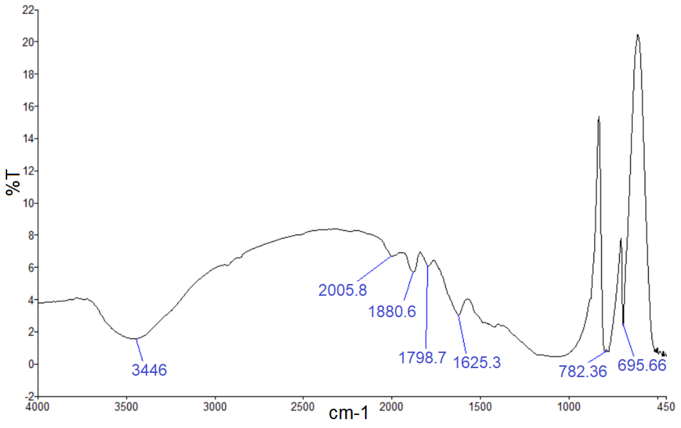
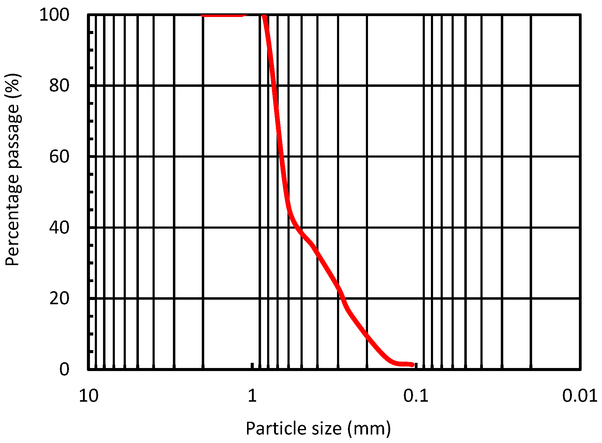
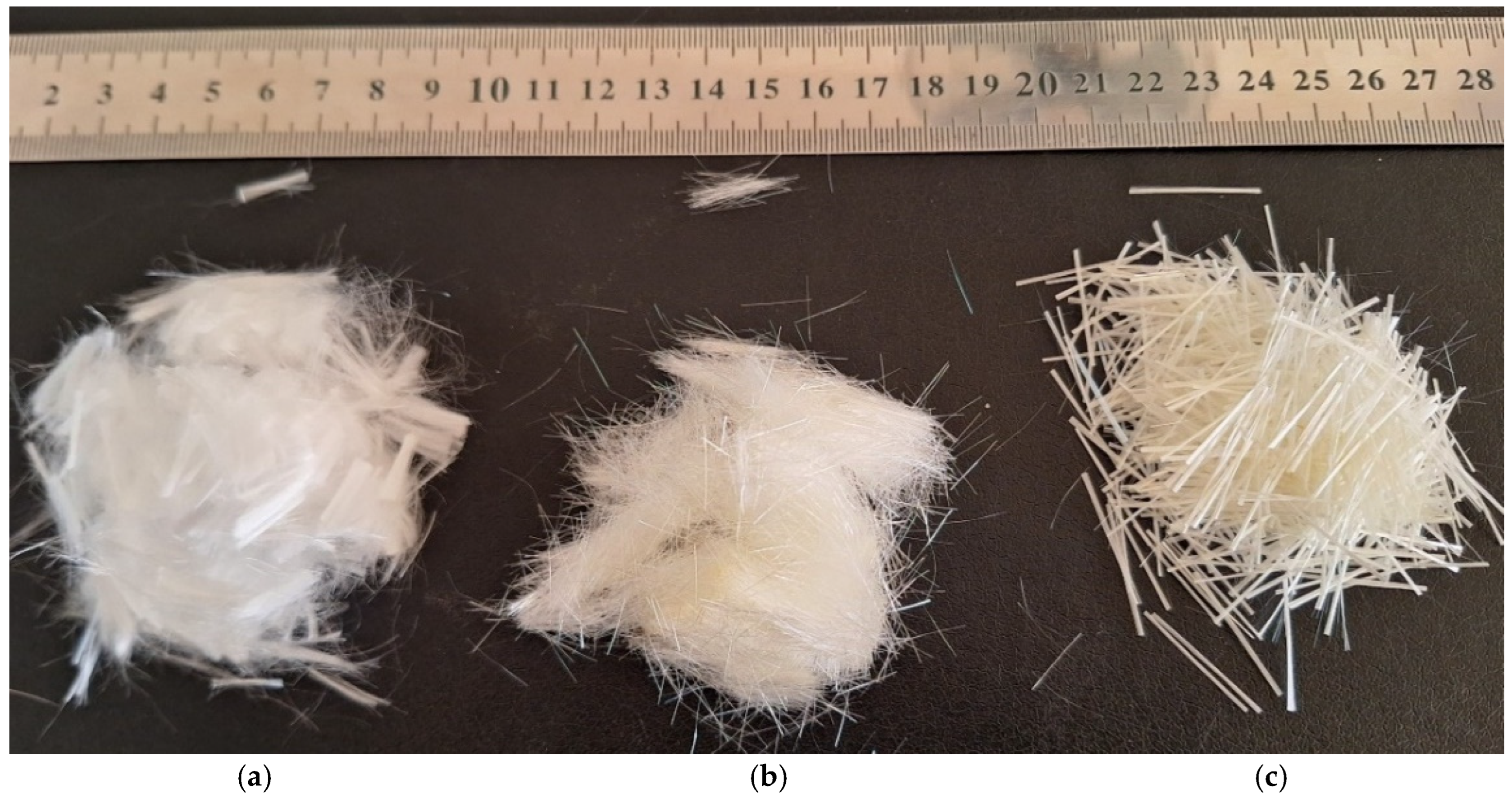
3.1. Materials and Mix Proportions

The constituents utilized for the fabrication of the requisite 3DPFCC mixes were locally sourced Portland pozzolana cement (CEM II/A-P 42.5 N), silica fume, calcium oxide (CaO), and natural siliceous sand with a maximum particle size of 0.80 mm. Calcium oxide (CaO) was selected to expedite the initial setting time of the combination and enhance buildability. Silica fume and calcium oxide constituted 10% each of the cement mass. A superplasticizer additive, typically composed of polycarboxylate and produced in accordance with ASTM C494/C494M-17 specification type E, was utilized to diminish water content and expedite the cement hydration process. The diminished water-to-binder ratio (W/B) necessitates the use of a superplasticizer (SP) in high-performance composites to improve workability and mitigate the impact of fiber addition. In the present study, the water-to-binder ratio was 0.25, and the superplasticizer concentration was 1%. The experimental test results of the XRF-Minerals for CEM II/A-P 42.5 N cement, silica fume, and calcium oxide are presented in Table 1. In contrast, the Fourier transform infrared spectroscopy (FTIR) analysis of silica fume is illustrated in Figure 1, which indicates the quality of the silica fume used in this study. The fine sand grading utilized in the various 3DPFCC mixes is depicted in Figure 2. The sand uniformity coefficient (Cu) was 3.25, while the coefficient of curvature (Cc) was 1.23.
This experimental inquiry utilized three types of synthetic fibers: polypropylene fiber (PP12), polyacrylonitrile high modulus fiber (PAC 251-60-12), and alkali-resistant glass fiber (ARG24). The polypropylene fiber (PP12) and the polyacrylonitrile high modulus fiber (PAC 251-60-12) measured 12 mm in length, while the alkali-resistant glass fiber (ARG24) measured 24 mm in length. The aspect ratios (Lf/df) of PP12, PAC 251-60-12, and ARG24 were 400, 143, and 1600, respectively, where Lf denotes the fiber length, and df represents the fiber diameter, as illustrated in Figure 3. All technical specifications and distinctive features of the fibers are enumerated in Table 2.
Four mixtures were prepared utilizing locally sourced materials, excluding the polyacrylonitrile high modulus fiber, to investigate the mechanical properties and flexural behavior of 3DPFCC reinforced with different types of fibers. The formulations for each of these mixtures are enumerated in Table 3. The reference mixture devoid of fiber was designated as G0. The three tested mixes, designated G1-PP, G2-PAC, and G3-ARG, comprised the fiber types PP12, PAC 251-60-12, and ARG24, respectively.

3.2. Mixing Procedure and Test Specimens

The 3D concrete mortar was prepared by amalgamating cement, silica fume, calcium oxide, and sand. Subsequently, three-quarters of the water was incorporated and blended, while the remaining portion was used to dilute the SP admixture. Ultimately, fibers were used during mixing to guarantee an even distribution. Upon completion of the mixing process, each specimen was poured into a leveled horizontal mold and maintained for 24 h. Subsequently, all specimens were dismantled and treated with burlap soaked in water for 28 days.
For each 3DPFCC mixture, six standard concrete cubes measuring 150 mm and six measuring 100 mm, along with six cylinders measuring 100 × 200 mm, were made and tested to ascertain their compressive strength in accordance with ECP 203-2020 [49], EN 12390-3 [57], ASTM C349-18, and ASTM C109/C109M-21.
Six concrete dog-bone specimens approved by JSCE No. 82-2008 [50] were utilized to conduct the uniaxial direct tensile test. Additionally, three cylinders measuring 100 × 200 mm were prepared and evaluated to obtain the tensile splitting strength for every mixture in accordance with ASTM C496/C496M-17 and relevant codes.
The flexural tensile strength test was conducted on three prismatic beam specimens, each with a cross-section of 150 × 150 mm and a length of 500 mm, in accordance with ASTM C78/C78M-22 and ECP 203-2020 [49].
All experimental specimens were supplied and cast in the Reinforced Concrete Laboratory at the Faculty of Engineering, Alexandria University. The experimental tests for cubes and cylinders were performed in the RC Laboratory at the Higher Institute of Engineering and Technology in King Marriott, Alexandria. In contrast, the flexural tests were executed in the RC Laboratory at the Faculty of Engineering, Alexandria University.

3.3. Testing Methods

3.3.1. Fresh Property Evaluation

The slump flow table test, as specified by ASTM C230/C230M-03 and ASTM C1437-15, was conducted on the fresh 3D mixes to assess the workability of the 3DPFCC. The shape stability test was conducted utilizing the cylinder stability test established by Kazemian et al. [32] to circumvent the printing of 3D concrete layers, given the limitations of the laboratory facilities. The cylinder possessed a diameter of 100 mm and a height of 80 mm, as illustrated in Figure 4.
In this test, the plastic cylinder was filled with two layers of fresh concrete, each measuring 40 mm. After applying the initial concrete layer, it was cemented with a tamping rod for fifteen repetitions. Likewise, the second layer was implemented utilizing the identical approach. Thereafter, the plastic cylinder was removed with caution. Any displacement within the concrete cylinder was measured. A stress of 44.70 KPa was applied using a steel weight, and the resulting displacement was documented.

3.3.2. Hardened Property Evaluation
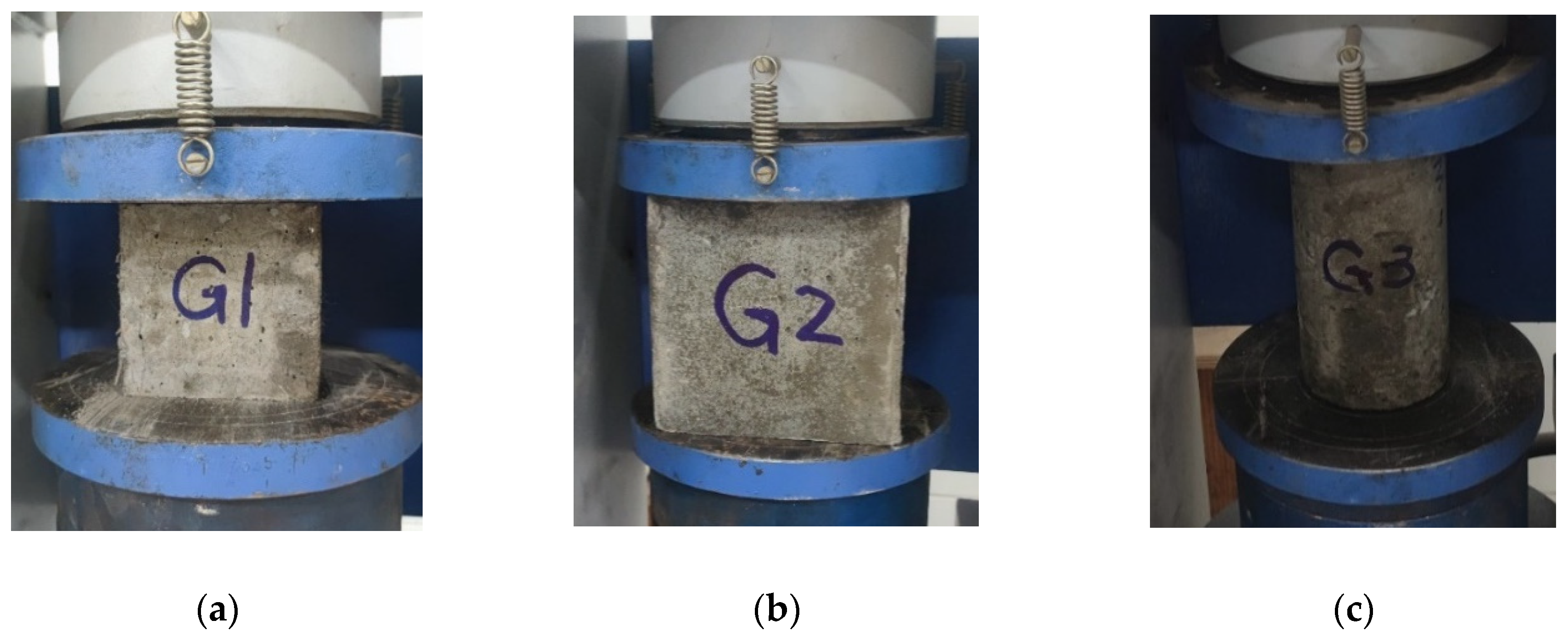
Compression Test

In order to determine the compressive strength of specimens, a compression test was performed after 28 days on standard concrete cubes measuring 150 mm and 100 mm, as well as on cylinders measuring 100 × 200 mm. This was executed using a force-controlled compression testing apparatus with a load capacity of 2000 kN and a rate of loading of 0.50 MPa per second, as illustrated in Figure 5.

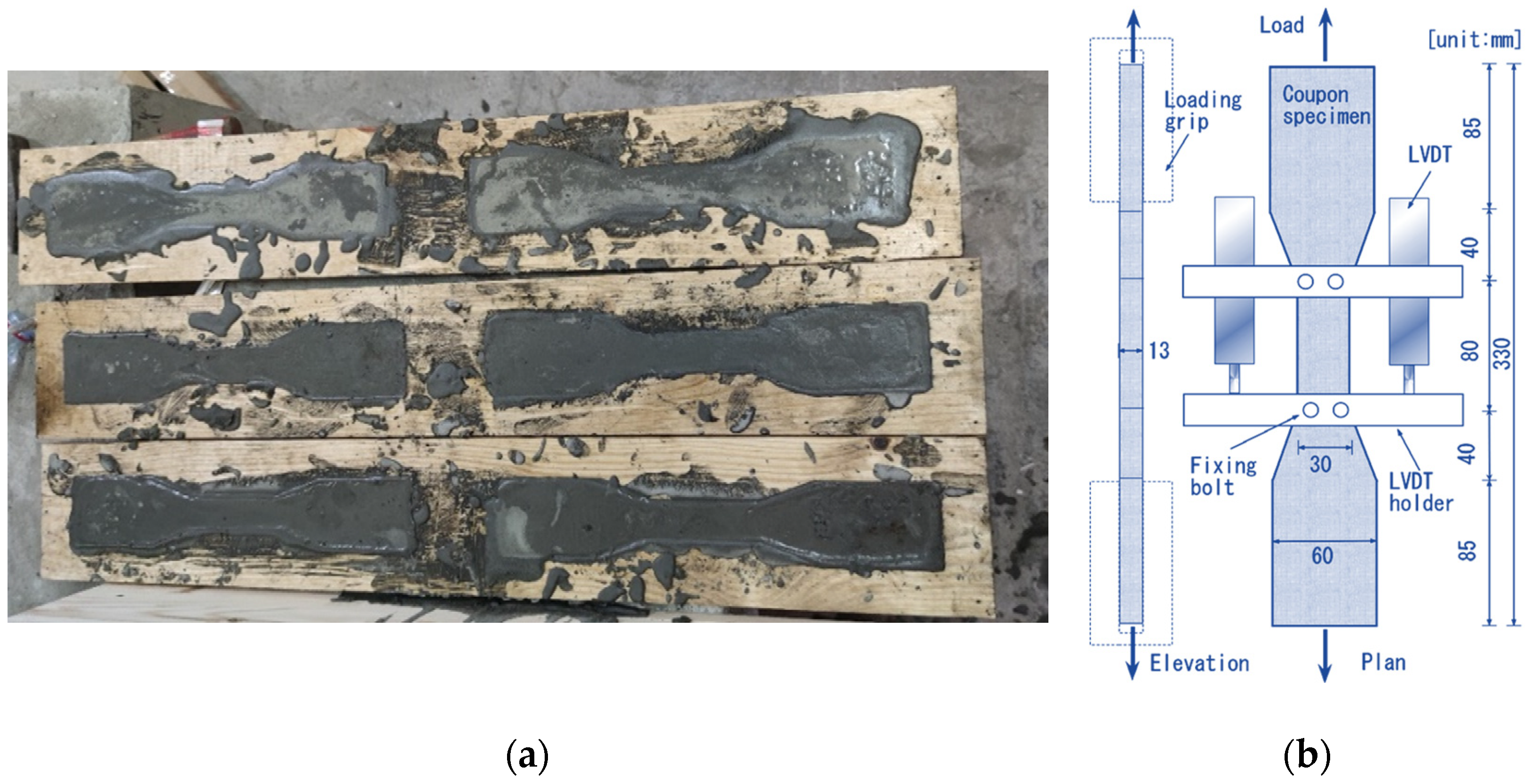
Uniaxial Direct Tensile Test

In the uniaxial direct tensile test conducted at 28 days, the cured dog-bone specimens, approved by the Japan Society of Civil Engineers (2008) (JSCE No. 82-2008) [50], were subjected to vertical loading via tensile testing equipment to assess the uniaxial direct tensile strength, as illustrated in Figure 6.

Splitting Tensile Test

The same compression test machine mentioned above was used to load the cured cylinders 100 × 200 mm horizontally for the splitting tensile test at 28 days in order to assess the tensile splitting strength, as illustrated in Figure 7.

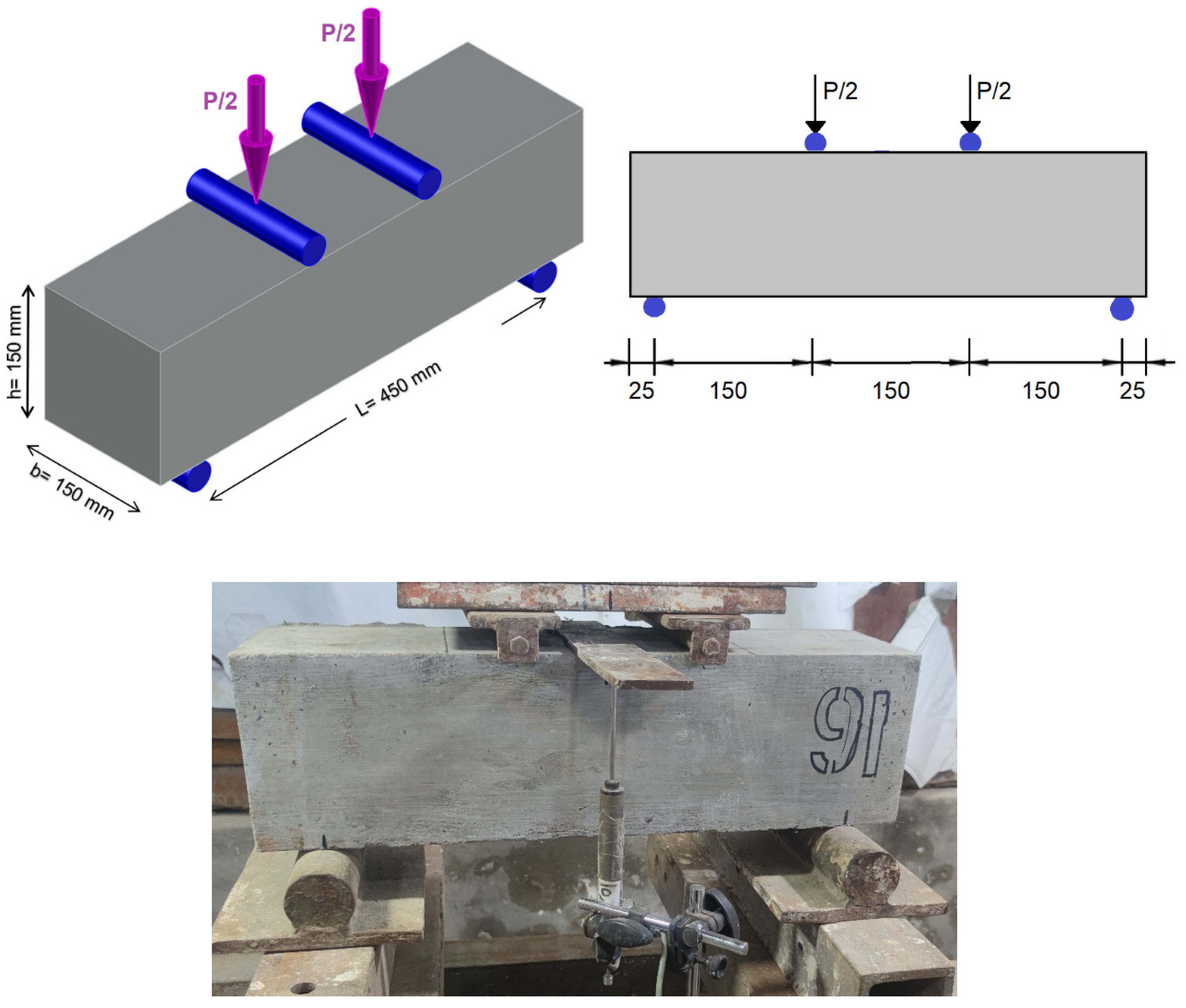
Flexural Bending Test

The flexural tensile strength of all prismatic beam specimens was ascertained by conducting a four-point bending test (Third-Point Loading Method) in accordance with the ASTM C78/C78M-22 standard. The prismatic beams were tested after 28 days, with dimensions of 500 × 150 × 150 mm. The flexural test was conducted using a vertical hydraulic lift with a load cell capacity of 1000 kN to apply two equivalent vertical loads. As illustrated in Figure 8, the distance between these masses was 150 mm, and the distance between the supports was 450 mm. Additionally, the deflection at the mid-span of the beam was measured at each load level using a linear variable differential transformer (LVDT), while a data acquisition system collected all data.

4. Results and Discussions
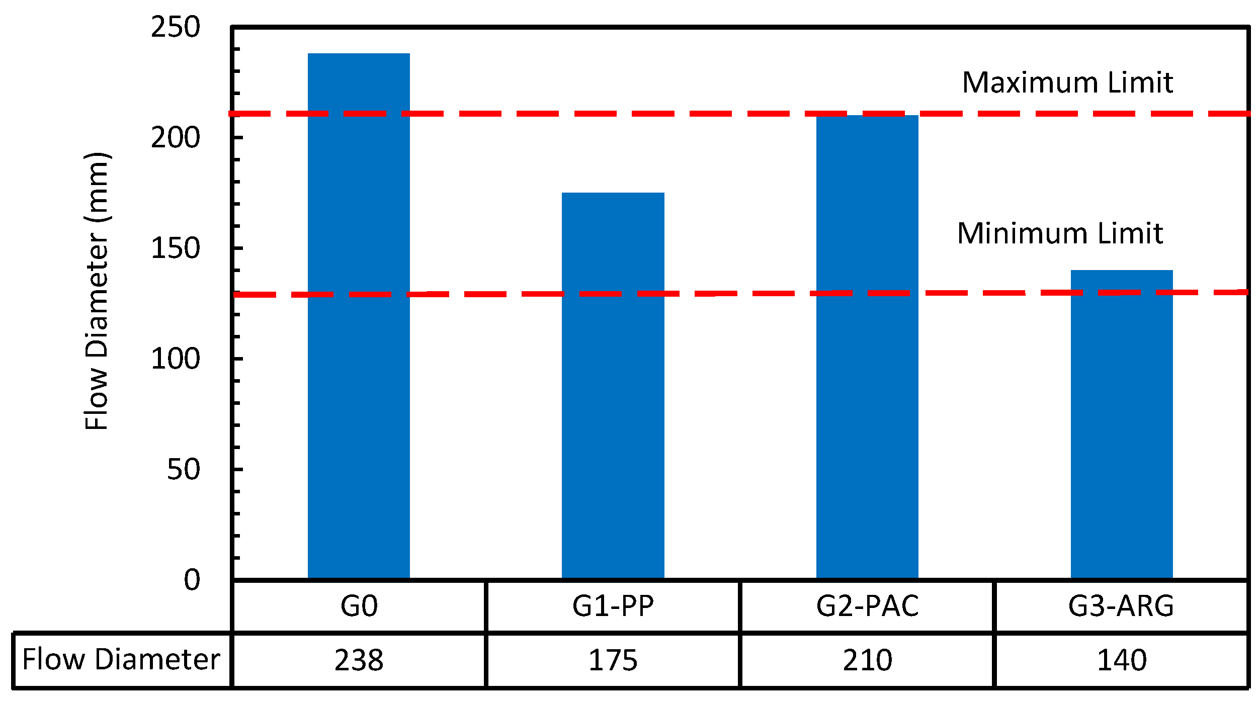
4.1. Workability

A slump flow test was performed on the 3DPFCC mixes, and the results for each mixture are presented in Figure 9. The slump flow diameter for 3D concrete mixtures should typically be regulated between 130 and 210 mm, as per Tay et al. [33], to ensure optimal pumpability and buildability. The slump flow diameters for the mixtures G0, G1-PP, G2-PAC, and G3-ARG were 238 mm, 175 mm, 210 mm, and 140 mm, respectively. The results indicated that fiber is a crucial factor in regulating the flow diameter of the mixture, and the addition of fibers resulted in a reduction of the flow diameter. The flow diameter of all fiber types utilized in this study conformed to the established standards. The polyacrylonitrile high-modulus fiber mixture had the greatest flow diameter among the three fiber mixes.

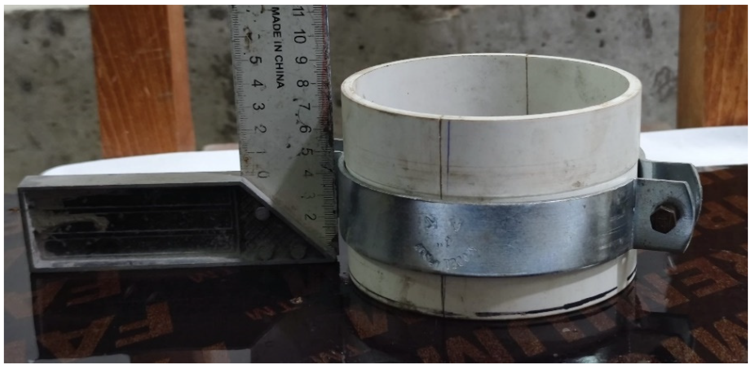
4.2. Shape Stability

The shape stability of the various mixtures was evaluated using the cylinder stability test established by Kazemian et al. [32]. The results of this evaluation are depicted in Figure 10. The average amount of deformation of 32 mm was reported for the reference mixture not containing any fibers (G0). On the other hand, the deformations recorded for the mixtures furnished with fiber (G1-PP, G2-PAC, and G3-ARG) were 24 mm, 18 mm, and 10 mm, according to the corresponding measurements. According to the findings that were obtained, the addition of fiber caused an improvement in the shape stability of the 3DPFCC combinations. The mixture provided with glass fiber (G3-ARG) demonstrated the highest level of performance.

4.3. Compressive Strength

The compressive strength test results that were performed on all of the 3DPFCC mixes that were put through this experimental investigation at 7 and 28 days are presented in Table 4. Figure 11 illustrates the compressive strength of the combinations at 7 and 28 days for the typical cubes that are 100 mm in size. In addition, the compressive strengths of all of the cubes and cylinders that were tested at the age of twenty-eight days are depicted in Figure 12.
The results obtained demonstrated that there was a moderate improvement in the compressive strength when compared with the combination that did not contain any fiber (G0). The cube with a diameter of 100 mm (fcu) had a compressive strength of 48.74 megapascals (MPa) at the age of seven days and 61.81 MPa at 28 days, respectively, for the G0. The compressive strength at 7 days was enhanced to 52.98 MPa, 49.80 MPa, and 50.07 Mpa by proposing a volume content of 1% PP, PAC, and ARG fibers. The compressive strength at 28 days increased to 67.18 MPa, 66.30 MPa, and 72.08 MPa, respectively.
Additionally, the utilization of PP, PAC, and ARG fiber with a volume content of 1% resulted in an increase of 9%, 7%, and 17%, respectively, in the compressive strength (fcu) achieved after 28 days as compared to the combination that did not contain fiber G0 (fcu,G0). The ratio of the compressive strength after 28 days between the cubes measuring 150 mm (fcu,150) and the cubes measuring 100 mm (fcu) was found to be between 97 and 99% for all of the evaluated specimens. It can be observed that the concrete compressive strengths of the cylinder specimens exhibit the same patterns and behaviors as those of the cube examples. Moreover, it is worth noting that the ratio of the compressive strength of the cylinder, which is 100 × 200 (fc), to the compressive strength of the concrete (fcu), was approximately 85%.
The crack pattern of the cubes and cylinders that were subjected to compression testing suggested, in general, that the incorporation of fibers appeared to have a substantial impact on the failure mechanism during the compression tests, as depicted in Figure 13. After attaining the peak compressive strength, the mixed specimens that did not contain fiber G0 failed explosively. This occurred because the lateral displacement of the specimens surpassed their tensile capacity. Coherence interaction between fibers and cementitious composites was discovered to contribute to the ductile compressive failure of mixture specimens reinforced with fibers (G1-PP, G2-PAC, and G3-ARG); this was demonstrated in the mixture specimens.

4.4. Uniaxial Tensile Strength

Figure 14 illustrates the relationship between uniaxial tensile stress and tensile strain of 3DPFCC mixes at 28 days, whereas Table 5 presents the data for uniaxial tensile strength (ft). As illustrated in Figure 14, the crack patterns of the studied dog-bone specimens for the 3DPFCC mixes indicated that the incorporation of fibers altered the uniaxial tensile behavior, transitioning it from brittle failure (G0) to ductile failure (G1-PP, G2-PAC, and G3-ARG). The uniaxial tensile strength of all specimens, including fibers, is almost equal; however, the mixture with glass fiber (G3-ARG) exhibits greater ductility compared to the other mixtures with different fiber types (G1-PP and G2-PAC), likely attributable to the superior aspect ratio of the glass fiber employed. The mixtures of G1-PP and G2-PAC exhibit very identical patterns and behaviors.
Furthermore, Table 5 illustrates the ratio of the uniaxial tensile strength (ft) to the uniaxial tensile strength of the fiber-free mixture (G0) (ft,G0), as well as the correlation between the uniaxial tensile strength (ft) and the square root of the compressive strength of a 100 mm cube at 28 days (fcu). The uniaxial tensile strength of the fiber-reinforced mixtures (G1-PP, G2-PAC, and G3-ARG) was superior to that of the combination without fibers (G0). The uniaxial tensile strength of the fiber-reinforced 3DPFCC mixtures varied between 4.2 MPa and 4.4 MPa, surpassing the 2.20 MPa of the fiberless mixture (G0). The enhancement of uniaxial tensile strength for the 3DPFCC mixtures G1-PP, G2-PAC, and G3-ARG was 99%, 100%, and 91%, respectively, in comparison to the fiber-free mixture (G0). The results demonstrated that the ratio f t / f c u   for all fiber-reinforced mixes, the range of 0.28 for the reference specimens devoid of fibers increased from 0.49 to 0.54. This increase in the ratio f t / f c u   is attributable to the influence of fiber on crack bridging.

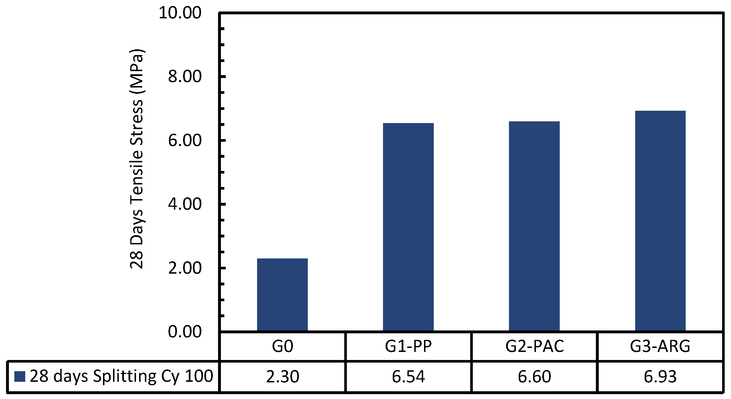
4.5. Tensile Splitting Strength

The crack pattern of the tested cylinders subjected to splitting for the 3DPFCC mixes showed that the inclusion of fibers modified the splitting tensile behavior, transitioning it from brittle failure (G0) to ductile failure (G1-PP, G2-PAC, and G3-ARG). The tensile splitting strength (fsp) results for the 100 × 200 mm cylinders at 28 days for all evaluated 3DPFCC mixtures are shown in Table 5 and depicted in Figure 15.
Table 5 depicts the ratio of the tensile splitting strength (fsp) to the tensile splitting strength of the fiber-free mixture G0 (fsp,G0), with the relationship between the tensile splitting strength (fsp) and the square root of the compressive strength of a 100 mm cube at 28 days (fcu). The tensile splitting strength of the fiber-reinforced mixtures (G1-PP, G2-PAC, and G3-ARG) exceeded that of the fiberless mixture (G0). The tensile splitting strength of the fiber-reinforced 3DPFCC combinations ranged from 6.54 MPa to 6.93 MPa, exceeding the 2.30 MPa seen in the fiber-free mixture (G0). The tensile splitting strength of the 3DPFCC combinations G1-PP, G2-PAC, and G3-ARG was enhanced by 184%, 187%, and 201%, respectively, in comparison to the reference mixture without fiber (G0). The findings demonstrated that the tensile splitting strength of alkali-resistant glass fiber was roughly 5% superior to that of polypropylene and polyacrylonitrile high-modulus fibers.

4.6. Flexural Tensile Strength

The flexure tensile strength (fctr), also known as the modulus of rapture, was used to characterize the flexural behavior of every beam taken. The highest flexural tensile strength that a beam section is capable of withstanding is referred to as the flexure tensile strength. This value can be determined by taking Equation (1):
f c t r = P m a x   L b h 2
where fctr: is the modulus of rupture, Pmax is the maximum applied load from the load cell (N), L is the beam span length (450 mm), b is the beam width (150 mm), and h is the beam height (150 mm).
Figure 16 depicts the crack patterns of the beams resulting from the flexural tests performed on all investigated specimens. The flexural tensile strength values for the 3DPFCC combinations at 28 days are presented in Table 5 and Figure 17.
Additionally, Table 5 presents the ratio of the flexural tensile strength (fctr) to that of the fiber-reference specimen G0 (fctr,G0), as well as the correlation between the flexural tensile strength (fctr) and the square root of the compressive strength of a 100 mm cube at 28 days (fcu). The flexural tensile strength of the fiber-reinforced specimens (G1-PP, G2-PAC, and G3-ARG) surpassed that of the specimen devoid of fibers (G0). The flexural tensile strengths of specimens G0, G1-PP, G2-PAC, and G3-ARG were 3.08 MPa, 7.13 MPa, 7.36 MPa, and 7.86 MPa, respectively. The flexural tensile strength of specimens with polypropylene, polyacrylonitrile, and alkali-resistant glass fibers (G1-PP, G2-PAC, and G3-ARG) surpassed that of the fiberless specimen (G0) by 132%, 139%, and 155%, respectively.
The findings demonstrated that the most significant improvement in flexural tensile strength was observed with alkali-resistant glass fibers, likely due to the fiber aspect ratio. The results indicated that the ratio of tensile splitting strength (fsp) to flexural tensile strength (fctr) ranged from 0.75 to 0.92, surpassing the 0.72 value recommended by ECP203-2020.

5. Finite Element Modeling of the Flexural Beam Test

This section aims to create a 3D nonlinear numerical model capable of predicting the nonlinear behavior of the tested beams reinforced with fiber under flexural loading, as illustrated in Figure 18. The proposed three-dimensional nonlinear numerical model was executed utilizing the finite element method through the software ANSYS Workbench 2023 R2 [48,58,59].

5.1. FEM Elements

The 3DPFCC beam, steel loading plate, and steel supports were modeled using the 3D element SOLID185 [59]. While the loading plates and steel supports measured 25 × 25 × 100 mm, the beam measured 150 × 150 × 500 mm. Every element was separated into smaller portions, each measuring 12.5 × 12.5 × 12.5 mm. The 3D nonlinear numerical model’s geometry and meshing are shown in Figure 18.

5.2. Concrete Modeling

The Menetrey–Willam constitutive model was employed for the nonlinear modeling of concrete (3DPFCC) with SOLID185 elements. This constitutive model relies on the Willam–Warnke yield surface [58], integrating dependency on three separate stress tensor invariants. The Menetrey–Willam model is typically favored for simulating the behavior of bound aggregates like concrete. The yield surfaces’ hardening–softening behavior is characterized by the functions Ωt and Ωc. These functions depend on the variables of compression and tension hardening. The Menetrey–Willam constitutive model offers two softening yield functions: linear and exponential softening functions. This study utilized the linear softening function, depicted in Figure 19, due to the properties of the 3DPFCC mixtures.
Adopting the Menetrey–Willam constitutive model using a linear softening yield function in ANSYS necessitates the specification of twelve parameters [58]. The values of the parameters were specified according to the experimental results shown in Table 6.

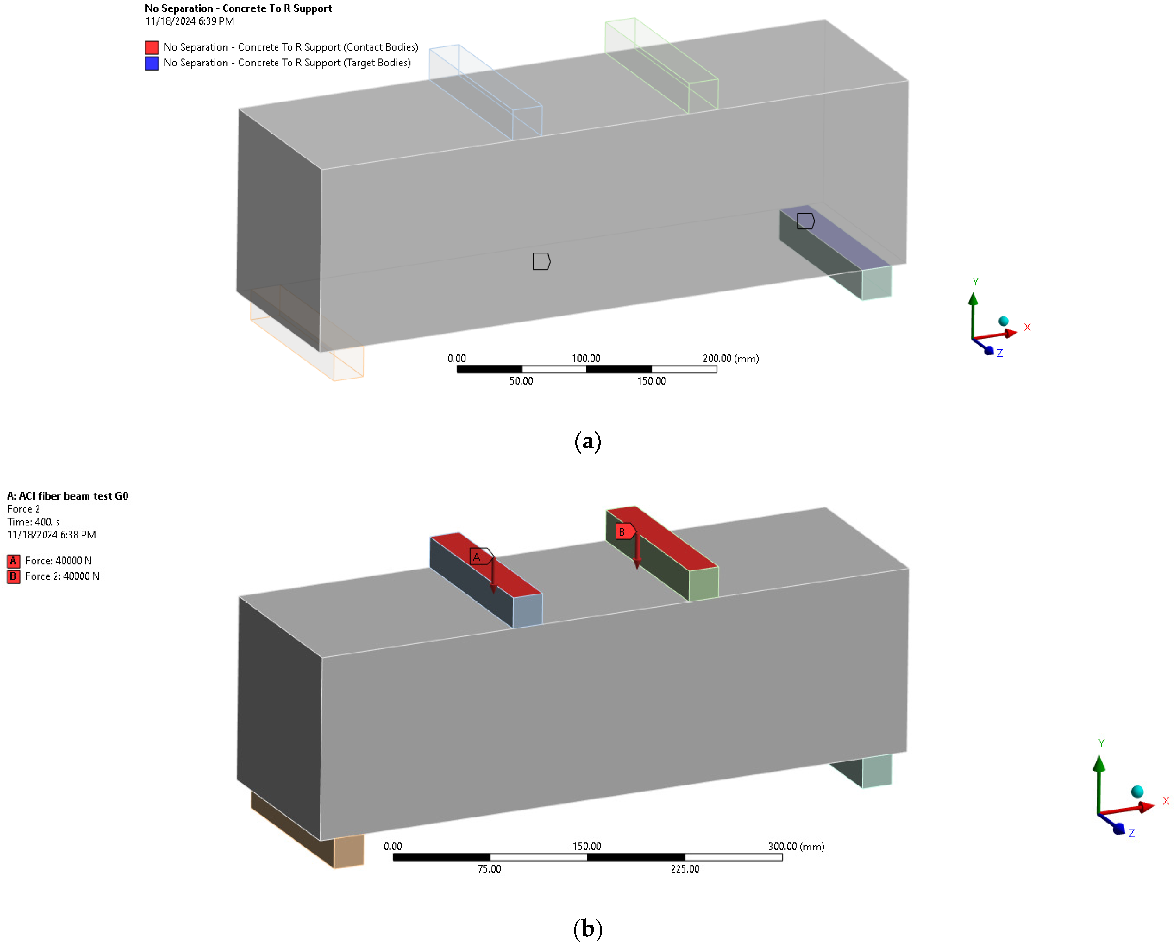
5.3. Supports and Loading Plates Modeling

A linear stress–strain relationship was employed to characterize the uniaxial behavior of the steel supports and loading plates utilizing νs, Es, and fy. The preceding numbers are presented in Table 6.

5.4. Constraints and Interactions

The multi-point constraint (MPC) formulation was utilized to model the interaction between the beam interface and the steel supports and loading plates, as depicted in Figure 20a, by specifying the contact surfaces using the (No Separation) type in the ANSYS workbench.

5.5. Loads and Boundary Conditions

As illustrated in Figure 20b, the beam was subjected to loading via a load control method, employing a steel loading plate and incrementally increasing the load by 0.5 kN for each step. The beam’s boundary conditions were considered simply supported.

5.6. Type of Analysis and Result Outputs

Static analysis was applied in all analyzed cases, and the Newton–Raphson method was adopted to obtain solutions for the nonlinear problem. The source of non-linearity in the present study is material nonlinearity. The geometric nonlinearity was neglected. Following each phase of this investigation, essential output data including deflections, stress components, strains, and reaction forces were obtained.

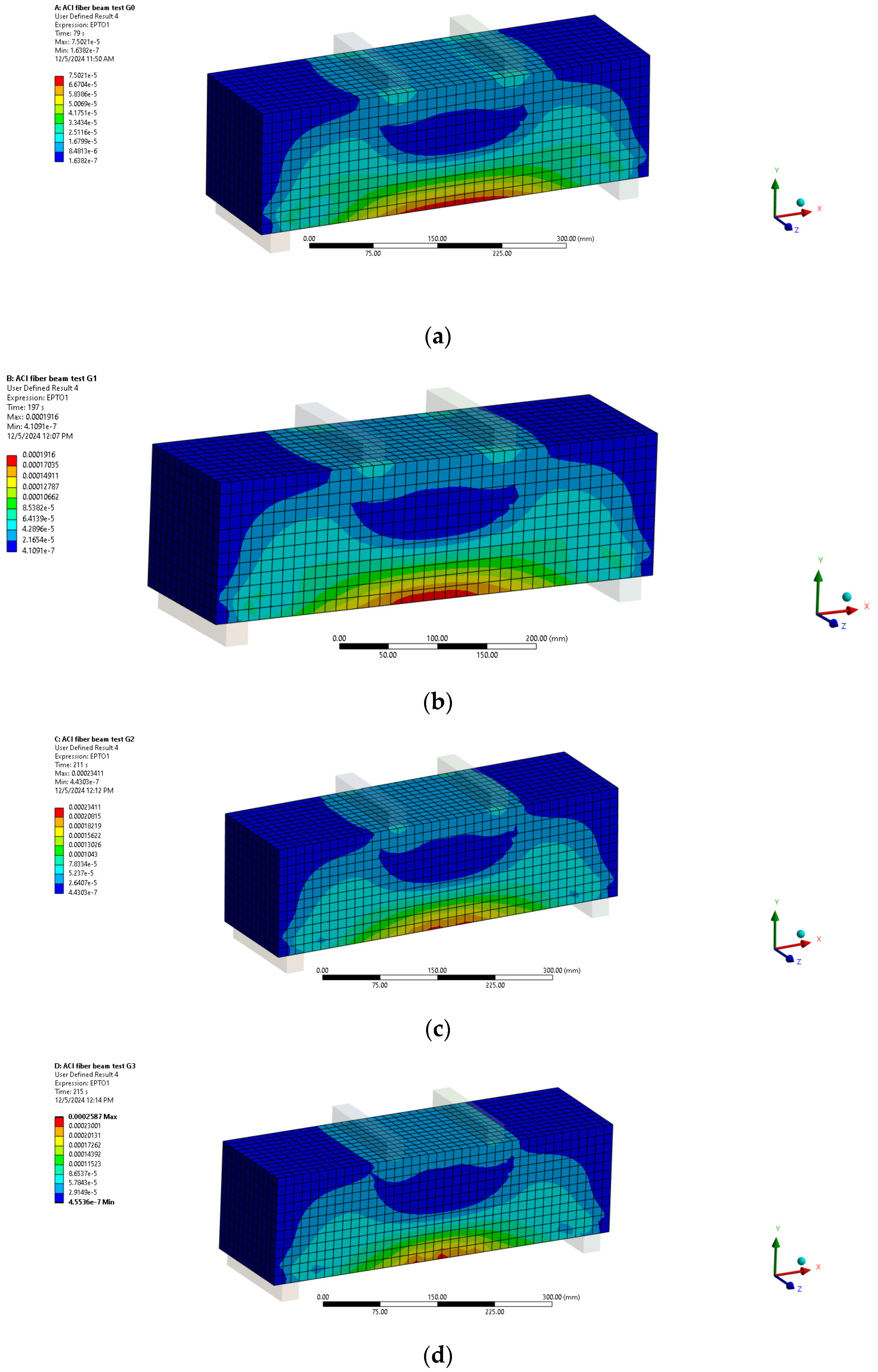
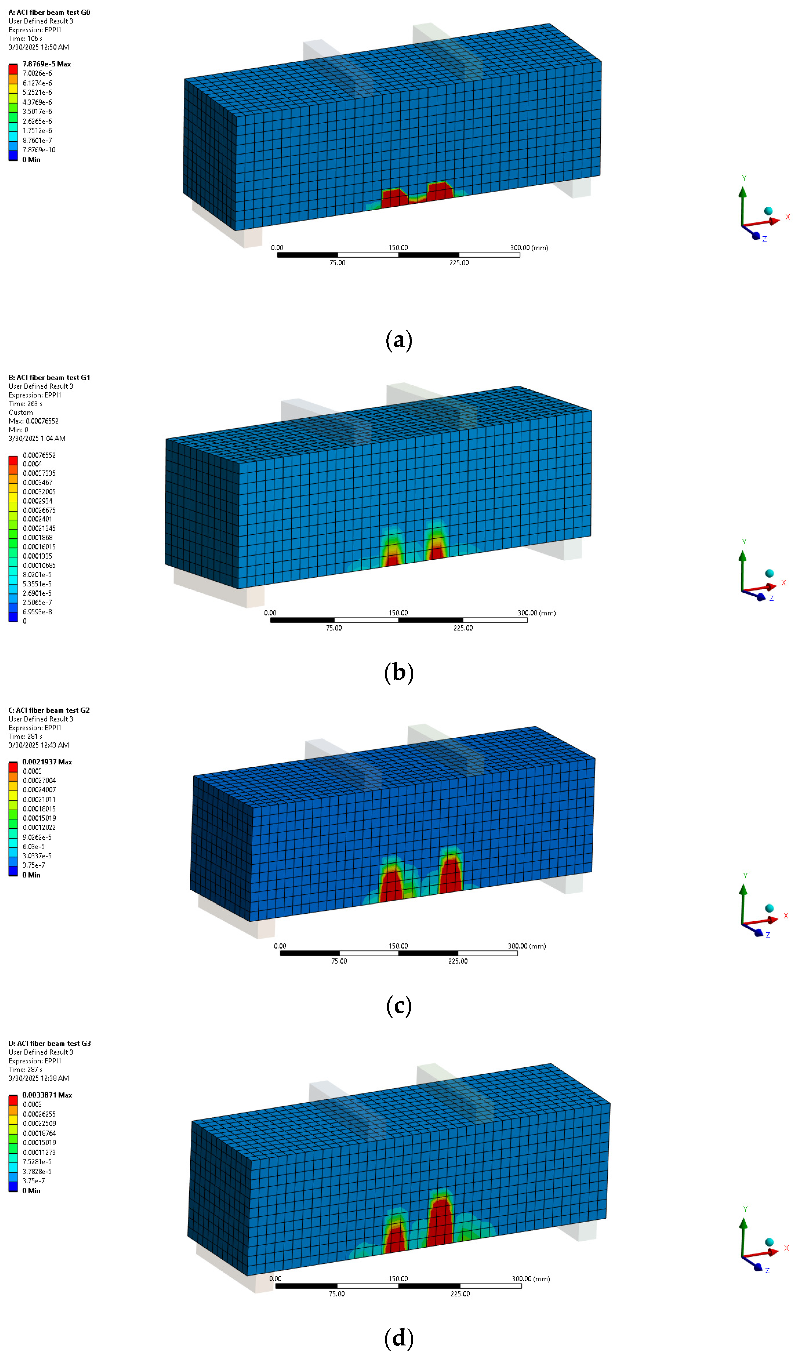
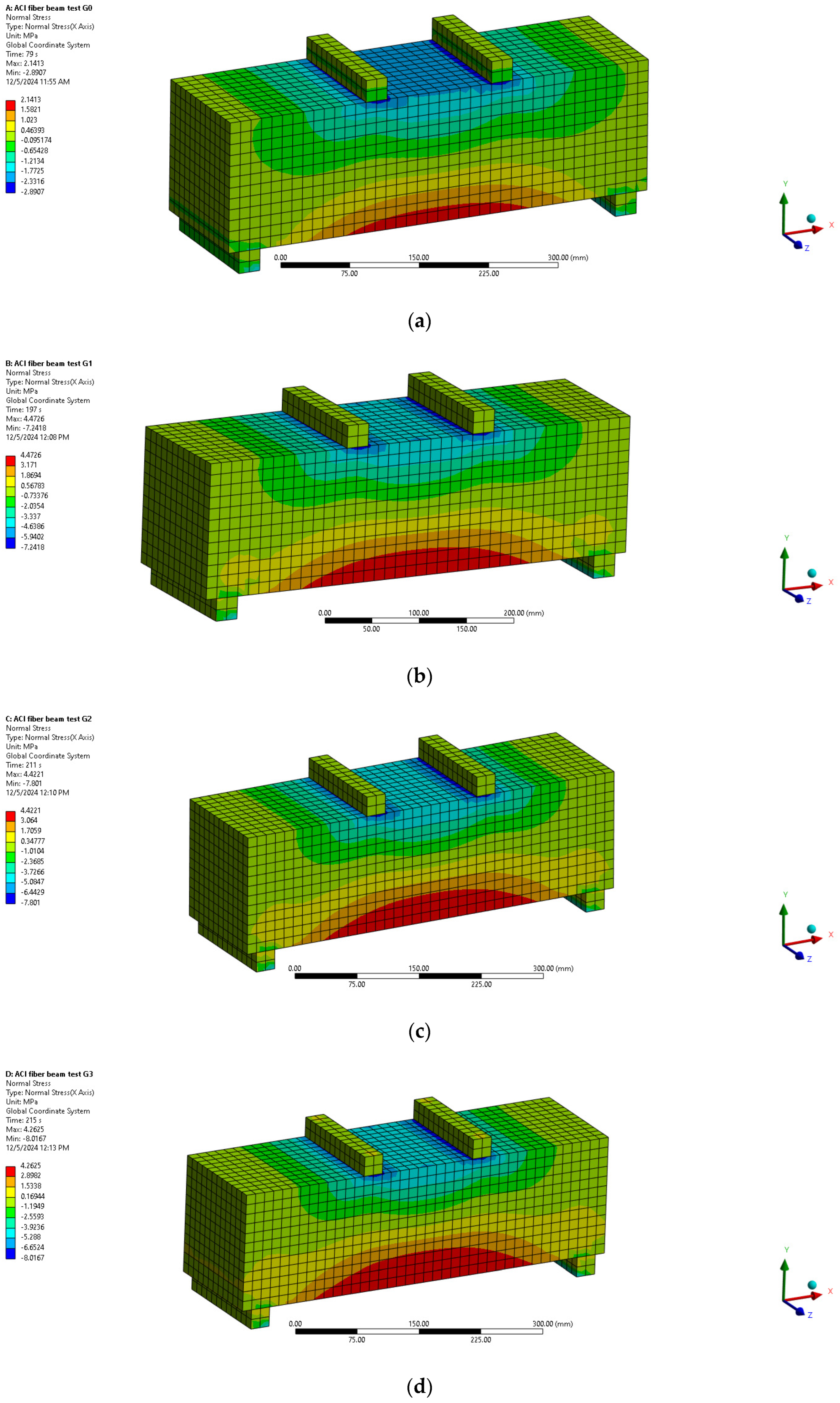
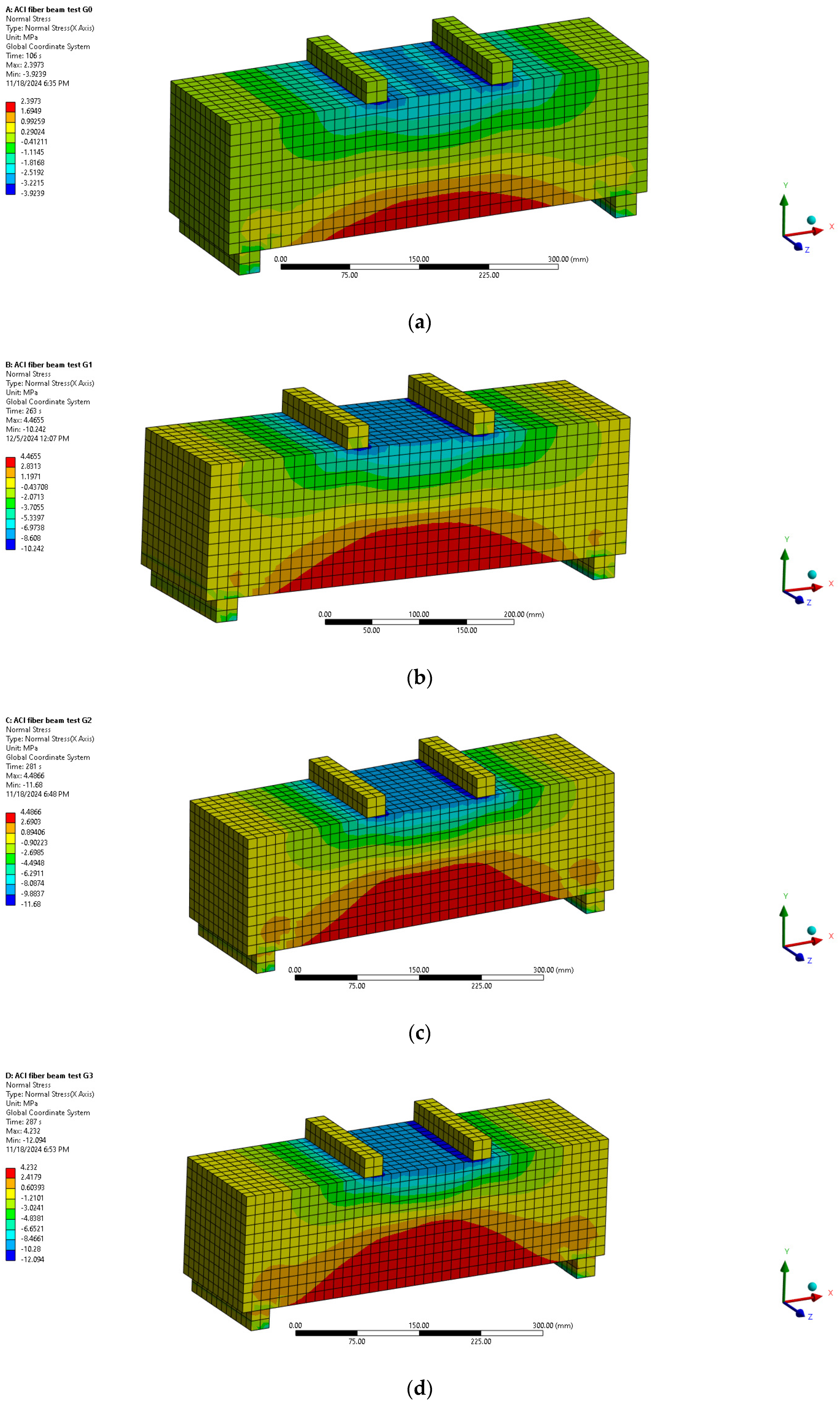
5.7. FEM Results and Validation

Table 7 displays the ultimate loads and flexural tensile strength of each 3DPFCC beam. The influence of variables on the structural responses of the proposed beams was assessed by comparing data from several specimens. The outcomes of both experiments and FEM were thoroughly contrasted and examined. The ultimate loads (Pu) and modulus of rupture (fctr) values for all the investigated 3DPFCC beams are presented in Table 7. The FEM study accurately predicted the ultimate stresses for the analyzed 3DPFCC beams, as illustrated in the table. The ratio of experimental results to FEM results is roughly 1.00. It is crucial to acknowledge that all FEMs exhibit uniform forms of failure and behavior. The results demonstrate that the concrete modeling employed in the analysis of 3DPFCC beams is accurate and appropriate.
Figure 21 and Figure 22 illustrate the maximum principal tensile total strains at two distinct loading stages, 0.75 Pu and Pu, for all 3DPFCC beams analyzed in this study. The principal tensile strains may signify the prediction of the crack pattern at the tension surface [48,59]. But, following Lubliner et al. (1989) [60,61], we can assume that cracking initiates at points where the tensile equivalent plastic strain is greater than zero and the maximum principal plastic strain is positive. The direction of the vector, normal to the crack plane, is assumed to be parallel to the direction of the maximum principal plastic strain. This direction can be viewed in Figure 23. Furthermore, the results demonstrate the congruity of the crack patterns between experimental and FEM outcomes.
The normal stress values in the X-direction at two different loading stages—0.75 Pu and Pu—for all 3DPFCC beams analyzed in this investigation are shown in Figure 24 and Figure 25. The largest compressive stress was centered at the upper top fiber of the beam, close to the loading area’s boundaries, according to the normal stress distribution in the X-direction. At the same time, between the load positions, the bottom fiber in the mid-span of the beam experienced the most tensile stress.
Table 7 presents a comparison between the finite element model (FEM) and experimental ultimate load results for all 3DPFCC beams. According to Table 7, the average ratio of the experimental ultimate load to the FEM ultimate load was 1.02, with a coefficient of variation (COV) of 2.24% and a coefficient of determination (R2) of 1.0.
In summary, the FEM results show that the Menetrey–Willam constitutive model with a linear softening yield function accurately reproduces the flexural behavior of all 3DPFCC beams, regardless of fiber inclusion, when compared to experimental observations. In order to reduce the substantial costs associated with experimental programs for large-scale 3DPFCC beams, a significant amount of numerical research could be conducted on 3DPFCC beams with various fiber types to examine the structural behavior of large-scale elements using the ANSYS finite element program.

6. Conclusions

This study provides an extensive experimental and numerical analysis to investigate the development of cementitious composites based on cement CEM II/A-P for three-dimensional concrete printing, integrating three different types of synthetic fiber. A total of 120 specimens were tested.
The experimental study examines three mixtures containing various fiber types (polypropylene, high-modulus polyacrylonitrile, and alkali-resistant glass fibers) alongside a reference mixture without fibers, emphasizing the flexural behavior and mechanical properties of 3D concrete printing utilizing CEM II/A-P.
The following can be concluded from the results of this experimental and numerical investigation:
  • The obtained results showed that adding the fibers decreased the flow diameter. Also, the flow diameter of all types of fibers used in this study was within the accepted limit, and the mixture provided with alkali-resistant glass fibers had the lowest flow diameter of all mixtures.
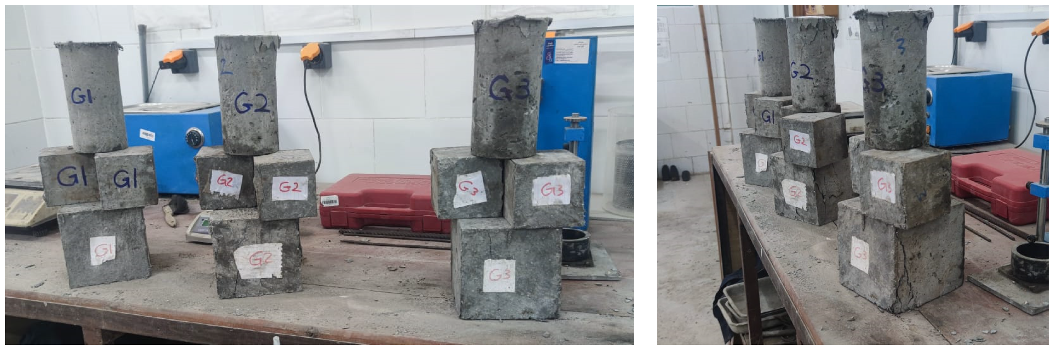
  • For all 3DPFCC mixtures, the cylinder stability test was performed to evaluate the shape stability, and the obtained results indicate that the fiber addition enhanced the shape stability of the 3DPFCC mixtures, and the best performance was for the mixture provided with glass fiber (G3-ARG).
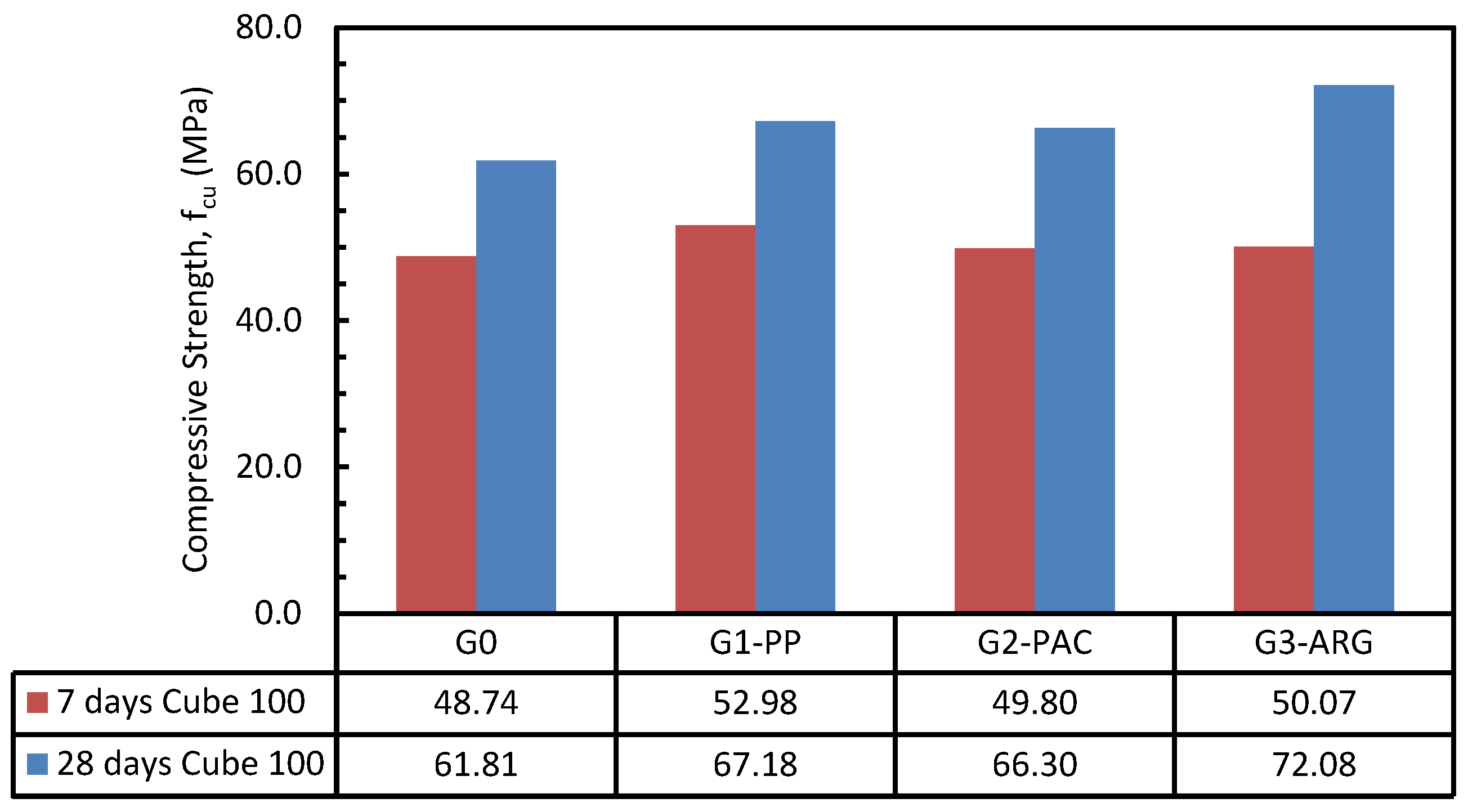
  • Generally, the obtained results showed a conservative increase in the compressive strength for mixtures with fiber compared to those without fiber (G0). The results indicate that using the PP, PAC, and ARG fiber with a volume content of 1% increased the 28 days compressive strength (fcu) compared to the mixture without fiber G0 (fcu,G0) by 9%, 7%, and 17%, respectively.
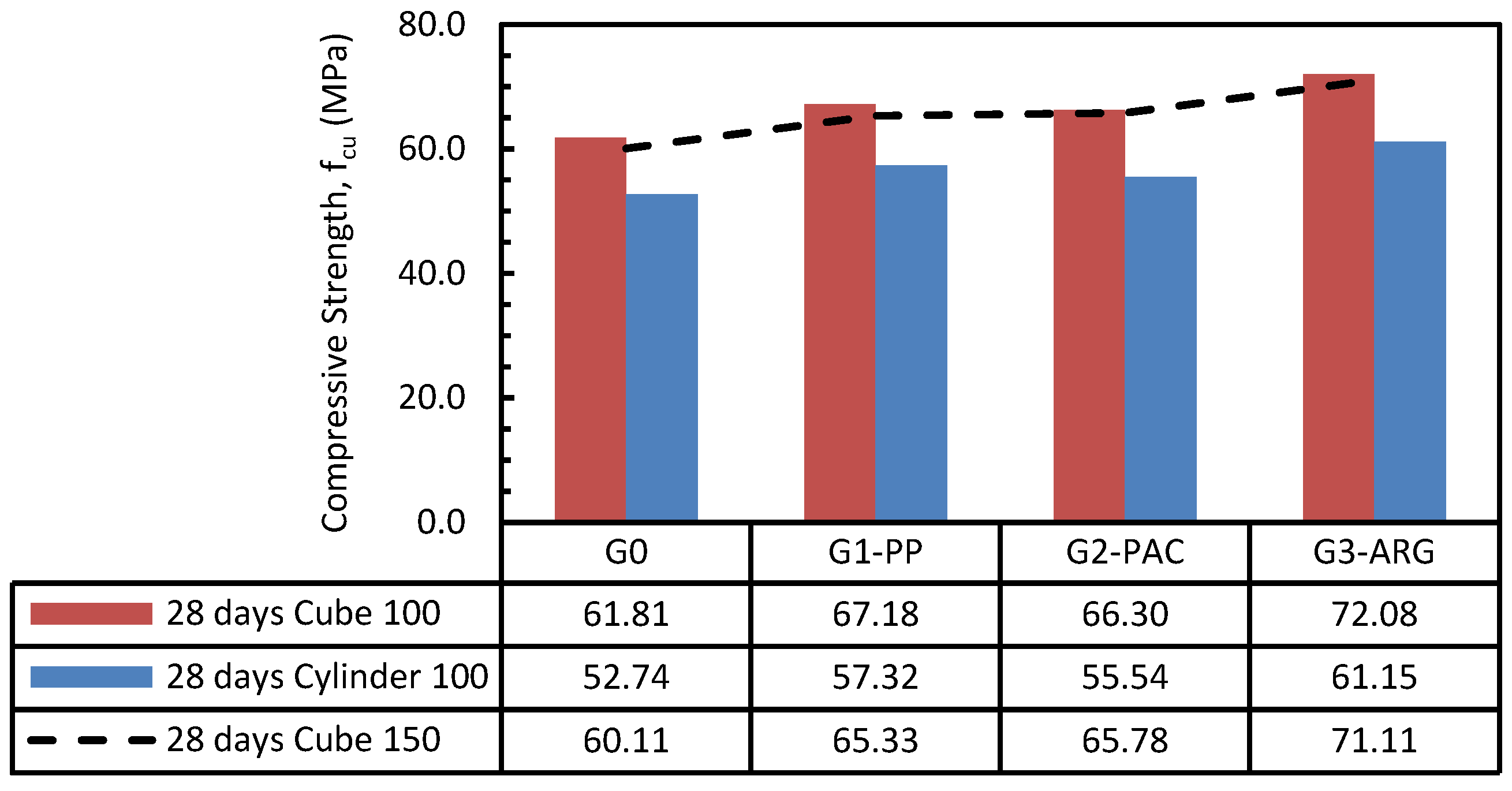
  • For all tested specimens, the ratio of the 28 days compressive strength between the cubes 150 mm (fcu,150) and the cubes 100 mm (fcu) ranged from 97 to 99%. For the cylinder specimens, the concrete compressive strengths showed the same trends and behavior as the cube specimens. In addition, the ratio of the cylinder compressive strength 100 × 200 (fc) to the concrete compressive strength (fcu) was about 85%.
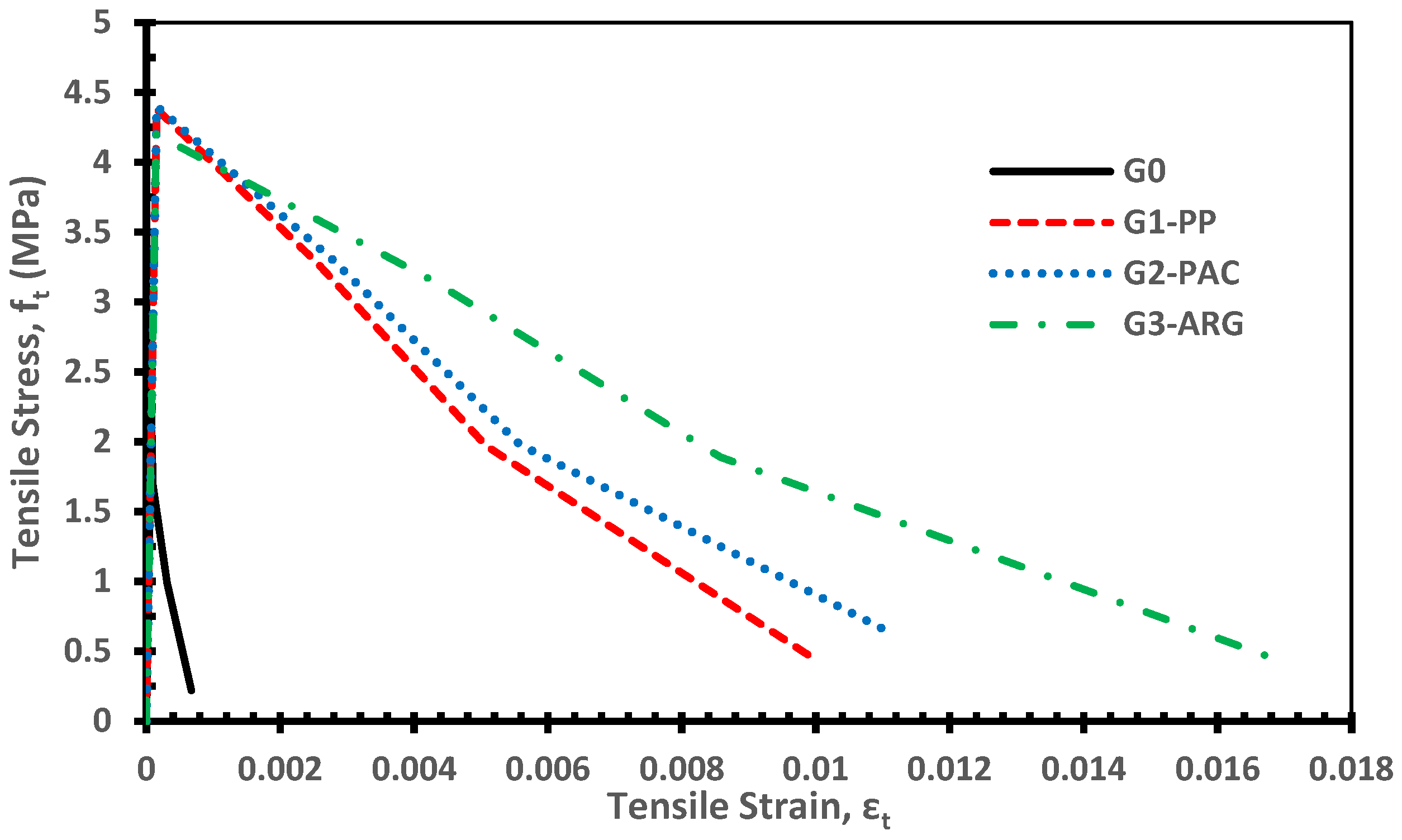
  • The crack pattern of the tested dog-bone specimens for the 3DPFCC mixtures showed that the addition of fibers changed the uniaxial tensile behavior of the mixtures and transferred it from brittle failure (G0) to ductile failure (G1-PP, G2-PAC, and G3-ARG).
  • The uniaxial tensile strength for all specimens with fibers is almost equal, but the mixture with glass fiber (G3-ARG) shows more ductile behavior than the other mixtures with other types of fibers (G1-PP and G2-PAC); this may be due to the higher aspect ratio of the used glass fiber. Also, the mixtures of G1-PP and G2-PAC show almost the same trends and behavior. In addition, the increase of the uniaxial tensile strength for the 3DPFCC mixtures G1-PP, G2-PAC, and G3-ARG were 99%, 100%, and 91% compared to the mixture without fibers (G0).
  • The tensile splitting strength of the fiber-reinforced mixtures (G1-PP, G2-PAC, and G3-ARG) was superior to that of the mixture without fibers (G0). The tensile splitting strength of the 3DPFCC mixtures G1-PP, G2-PAC, and G3-ARG increased by 184%, 187%, and 201%, respectively, compared to the mixture without fiber (G0). The results indicated that the alkali-resistant glass fiber tensile splitting strength was approximately 5% greater than that of the polypropylene and polyacrylonitrile high-modulus fibers.
  • The flexural tensile strength of the specimens containing polypropylene, polyacrylonitrile, and alkali-resistant glass fibers (G1-PP, G2-PAC, and G3-ARG) exceeded that of the fiberless specimen (G0) by 132%, 139%, and 155%, respectively. The results indicated that the greatest enhancement in flexural tensile strength occurred with the use of alkali-resistant glass fibers, which may be attributable to the fiber aspect ratio.
  • The findings revealed that the ratio of tensile splitting strength (fsp) to flexural tensile strength (fctr) varied from 0.75 to 0.92, exceeding the 0.72 value suggested by ECP203-2020.
  • The FEM results, utilizing the Menetrey–Willam constitutive model with a linear softening yield function, accurately predicted the ultimate loads for the tested 3DPFCC beams, with the ratio of experimental to FEM values approximating 1.00.
  • The results demonstrate the compatibility of the crack patterns between experimental and FEM outcomes. It can be concluded that the Menetrey–Willam constitutive model, featuring a linear softening yield function, effectively simulates the flexural behavior of 3DPFCC beams with CEM II/A-P.

Author Contributions

A.M.Y.: Writing—original draft, Visualization, Validation, Supervision, Software, Resources, Project administration, Methodology, Writing—review and editing, Investigation, Formal analysis, Data curation, Conceptualization. M.A.H.: Supervision, Project administration, Funding acquisition. M.G.A.: Writing—original draft, Writing—review and editing, Visualization, Validation, Methodology, Investigation, Formal analysis, Data curation, Software, Conceptualization. All authors have read and agreed to the published version of the manuscript.

Funding

The APC was funded by [INTI International University in Malaysia] grant number [INTIFEQS-01–06- 2023].

Data Availability Statement

All data used or analyzed during this study are included in this article.

Acknowledgments

The authors would like to thank TesserianTech S.R.L, Italy, for their support and help in executing this experimental research work through the research fund. Also, we would like to thank Schwarzwälder Textil-Werke (STW), Germany, for providing the polyacrylonitrile high-modulus fiber. In addition, we would like to express our deepest gratitude to the Department of Structural Engineering, Faculty of Engineering, Alexandria University, Egypt for the immense help in executing the experimental part of the research and to INTI-IU-Malaysia for the generous support through the research grant INTI-FEQS-01-06-2023 which played a pivotal role in the publishing of this research.

Conflicts of Interest

The author declares no conflicts of interest.

References

  1. Menna, C.; Mata-Falcón, J.; Bos, F.P.; Vantyghem, G.; Ferrara, L.; Asprone, D.; Salet, T.; Kaufmann, W. Opportunities and challenges for structural engineering of digitally fabricated concrete. Cem. Concr. Res. 2020, 133, 106079. [Google Scholar] [CrossRef]
  2. Lee, S. Properties of Waste Incineration Ash Added Cementitious Material for Possible Usage in 3D Printing. Master’s Dissertation, Yonsei University, Department of Structural Engineering, Faculty of Engineering, Seoul, Republic of Korea, 2017. [Google Scholar]
  3. Nerella, V.N.; Krause, M.; Mechtcherine, V. Direct printing test for buildability of 3D-printable concrete considering economic viability. Autom. Constr. 2020, 109, 102986. [Google Scholar] [CrossRef]
  4. Khoshnevis, B.; Dutton, R. Innovative rapid prototyping process makes large sized, smooth surfaced complex shapes in a wide variety of materials. Mater. Technol. 1998, 13, 53–56. [Google Scholar] [CrossRef]
  5. Heidarnezhad, F.; Zhang, Q. Shotcrete based 3D concrete printing: State of art, challenges, and opportunities. Constr. Build. Mater. 2022, 323, 126545. [Google Scholar] [CrossRef]
  6. Aboelhassan, M.G. Future of Sustainable Construction Industry: A Review of Research, Practice and Applications of 3D Concrete Printing. Adv. Civ. Eng. Technol. 2023, 5, 1–8. [Google Scholar] [CrossRef]
  7. Paolini, A.; Kollmannsberger, S.; Rank, E. Additive manufacturing in construction: A review on processes, applications, and digital planning methods. Addit. Manuf. 2019, 30, 100894. [Google Scholar] [CrossRef]
  8. Liu, G.; Bai, E.; Xu, J.; Wang, T.; Chang, S. Research Status and Development Prospect of 3D Printing Concrete Materials. In Proceedings of the IOP Conference Series: Earth and Environmental Science; IOP Publishing: Bristol, UK, 2019; p. 032014. [Google Scholar]
  9. Khan, M. Mix suitable for concrete 3D printing: A review. Mater. Today Proc. 2020, 32, 831–837. [Google Scholar] [CrossRef]
  10. Krishnaraja, A.; Guru, K. 3D Printing Concrete: A Review. In Proceedings of the IOP Conference Series: Materials Science and Engineering; IOP Publishing: Bristol, UK, 2021; p. 012033. [Google Scholar]
  11. Asprone, D.; Auricchio, F.; Menna, C.; Mercuri, V. 3D printing of reinforced concrete elements: Technology and design approach. Constr. Build. Mater. 2018, 165, 218–231. [Google Scholar] [CrossRef]
  12. Ahmed, Z.Y.; Bos, F.P.; Wolfs, R.J.; Salet, T.A. Design considerations due to scale effects in 3D concrete printing. In Proceedings of the 8th Arab Society for Computer Aided Architectural Design, London, UK, 7–8 November 2016. [Google Scholar]
  13. Bos, F.P.; Ahmed, Z.Y.; Wolfs, R.J.; Salet, T.A. 3D Printing Concrete with Reinforcement. In Proceedings of the High Tech Concrete: Where Technology and Engineering Meet, Maastricht, The Netherlands, 12–14 June 2017. [Google Scholar]
  14. Gebhard, L.; Mata-Falcón, J.; Anton, A.; Dillenburger, B.; Kaufmann, W. Structural behaviour of 3D printed concrete beams with various reinforcement strategies. Eng. Struct. 2021, 240, 112380. [Google Scholar] [CrossRef]
  15. Kloft, H.; Empelmann, M.; Hack, N.; Herrmann, E.; Lowke, D. Reinforcement strategies for 3D-concrete-printing. Civ. Eng. Des. 2020, 2, 131–139. [Google Scholar] [CrossRef]
  16. Lim, S.; Buswell, R.A.; Le, T.T.; Austin, S.A.; Gibb, A.G.; Thorpe, T. Developments in construction-scale additive manufacturing processes. Autom. Constr. 2012, 21, 262–268. [Google Scholar] [CrossRef]
  17. Lim, S.; Buswell, R.A.; Valentine, P.J.; Piker, D.; Austin, S.A.; De Kestelier, X. Modelling curved-layered printing paths for fabricating large-scale construction components. Addit. Manuf. 2016, 12, 216–230. [Google Scholar] [CrossRef]
  18. Nishiwaki, T.; Miyata, Y.; Furue, S.; Fukatsu, S.; Kajita, H. Reinforcing interlayers of three-dimensional-printed mortar using metal fiber insertion. ACI Mater. J. 2021, 118, 331–340. [Google Scholar]
  19. Hack, N.; Bahar, M.; Hühne, C.; Lopez, W.; Gantner, S.; Khader, N.; Rothe, T. Development of a robot-based multi-directional dynamic fiber winding process for additive manufacturing using shotcrete 3D printing. Fibers 2021, 9, 39. [Google Scholar] [CrossRef]
  20. Jo, J.H.; Jo, B.W.; Cho, W.; Kim, J.-H. Development of a 3D printer for concrete structures: Laboratory testing of cementitious materials. Int. J. Concr. Struct. Mater. 2020, 14, 1–11. [Google Scholar] [CrossRef]
  21. Şahin, H.G.; Mardani-Aghabaglou, A. Assessment of materials, design parameters and some properties of 3D printing concrete mixtures; a state-of-the-art review. Constr. Build. Mater. 2022, 316, 125865. [Google Scholar] [CrossRef]
  22. Antoni, A.; Agraputra, A.; Teopilus, D.; Sunaryo, A.; Mulyadi, M.; Pudjisuryadi, P.; Chandra, J.; Hardjito, D. Investigation of the material mixtures and fiber addition for 3D concrete printing. In Proceedings of the IOP Conference Series: Earth and Environmental Science; IOP Publishing: Bristol, UK, 2021; p. 012011. [Google Scholar]
  23. Yuan, Q.; Zuo, S.; Li, Z.; Shi, C.; Wu, Q. Optimizing Three-Dimensional Printing Binder Composed of Ordinary Portland Cement and Calcium Sulfoaluminate Cement with Retarders. ACI Mater. J. 2021, 118, 155–165. [Google Scholar]
  24. Ko, L.; Moro, S.; Bury, J.; Vickers, T.; Sachsenhauser, B.; Mönnig, S. Rheology and Setting Control of Concrete for Digital Construction. ACI Mater. J. 2021, 118, 167–175. [Google Scholar]
  25. Murcia, D.H.; Abdellatef, M.; Genedy, M.; Taha, M. Rheological Characterization of Three-Dimensional-Printed Polymer Concrete. ACI Mater. J. 2021, 118, 189–201. [Google Scholar]
  26. Sonebi, M.; Dedenis, M.; Amziane, S.; Abdalqader, A.; Perrot, A. Effect of Red Mud, Nanoclay, and Natural Fiber on Fresh and Rheological Properties of Three-Dimensional Concrete Printing. ACI Mater. J. 2021, 118, 97–110. [Google Scholar]
  27. Douba, A.; Kawashima, S. Use of nanoclays and methylcellulose to tailor rheology for three-dimensional concrete printing. ACI Mater. J. 2021, 118, 275–289. [Google Scholar]
  28. Tao, Y.; Vantyghem, G.; Lesage, K.; Yuan, Y.; De Corte, W.; Van Tittelboom, K.; De Schutter, G. Adhesion properties of printable polymer-modified concrete for rock tunnel linings. ACI Mater. J. 2021, 118, 61–73. [Google Scholar]
  29. Kruger, J.; Cho, S.; van den Heever, M.; Bester, F.; van Rooyen, A.; van Zij, G. Nanotechnology for Improved Three-Dimensional Concrete Printing Constructability. ACI Mater. J. 2021, 118, 19–28. [Google Scholar]
  30. Kruger, J.; Zeranka, S.; van Zijl, G. 3D concrete printing: A lower bound analytical model for buildability performance quantification. Autom. Constr. 2019, 106, 102904. [Google Scholar] [CrossRef]
  31. Liu, C.; Yue, S.; Zhou, C.; Sun, H.; Deng, S.; Gao, F.; Tan, Y. Anisotropic mechanical properties of extrusion-based 3D printed layered concrete. J. Mater. Sci. 2021, 56, 16851–16864. [Google Scholar] [CrossRef]
  32. Kazemian, A.; Yuan, X.; Cochran, E.; Khoshnevis, B. Cementitious materials for construction-scale 3D printing: Laboratory testing of fresh printing mixture. Constr. Build. Mater. 2017, 145, 639–647. [Google Scholar] [CrossRef]
  33. Tay, Y.W.D.; Qian, Y.; Tan, M.J. Printability region for 3D concrete printing using slump and slump flow test. Compos. Part B Eng. 2019, 174, 106968. [Google Scholar] [CrossRef]
  34. Wi, K.; Hong, J.; Wang, K. Determining printable zone of three-dimensional-printable mortar using flow table tests. ACI Mater. J. 2021, 118, 75–85. [Google Scholar]
  35. Zareiyan, B.; Khoshnevis, B. Effects of interlocking on interlayer adhesion and strength of structures in 3D printing of concrete. Autom. Constr. 2017, 83, 212–221. [Google Scholar] [CrossRef]
  36. Xu, J.; Ding, L.; Cai, L.; Zhang, L.; Luo, H.; Qin, W. Volume-forming 3D concrete printing using a variable-size square nozzle. Autom. Constr. 2019, 104, 95–106. [Google Scholar] [CrossRef]
  37. Seo, E.-A.; Kim, W.-W.; Kim, S.-W.; Kwon, H.-K.; Lee, H.-J. Mechanical properties of 3D printed concrete with coarse aggregates and polypropylene fiber in the air and underwater environment. Constr. Build. Mater. 2023, 378, 131184. [Google Scholar] [CrossRef]
  38. Aramburu, A.; Calderon-Uriszar-Aldaca, I.; Puente, I.; Castano-Alvarez, R. Effects of 3D-printing on the tensile splitting strength of concrete structures. Case Stud. Constr. Mater. 2024, 20, e03090. [Google Scholar] [CrossRef]
  39. Arif, M.; Jan, F.; Rezzoug, A.; Afridi, M.A.; Luqman, M.; Khan, W.A.; Kujawa, M.; Alabduljabbar, H.; Khan, M. Data-driven models for predicting compressive strength of 3D-printed fiber-reinforced concrete using interpretable machine learning algorithms. Case Stud. Constr. Mater. 2024, 21, e03935. [Google Scholar] [CrossRef]
  40. Cai, J.; Wang, J.; Zhang, Q.; Du, C.; Meloni, M.; Feng, J. State-of-the-art of mechanical properties of 3D printed concrete. Case Stud. Constr. Mater. 2024, 21, e03847. [Google Scholar] [CrossRef]
  41. Luo, S.; Jin, W.; Wu, W.; Zhang, K. Rheological and mechanical properties of polyformaldehyde fiber reinforced 3D-printed high-strength concrete with the addition of fly ash. J. Build. Eng. 2024, 98, 111387. [Google Scholar] [CrossRef]
  42. Sun, J.; Liu, S.; Ma, Z.; Wang, D.; Wang, Y.; Zhao, H.; Huang, B.; Saafi, M.; Wang, X. 3D printed lightweight concrete containing surface pretreated coal gangue. Case Stud. Constr. Mater. 2024, 20, e02906. [Google Scholar] [CrossRef]
  43. Wang, L.; Wang, F.; Li, R.; Wang, Q. Interfacial constitutive model of 3D printed fiber reinforced concrete composites and its experimental validation. Case Stud. Constr. Mater. 2024, 20, e02807. [Google Scholar] [CrossRef]
  44. Ma, W.; Wang, G.; Zhou, Y.; Xu, Q.; Dai, Y. Polyacrylonitrile fiber reinforced 3D printed concrete: Effects of fiber length and content. J. Build. Eng. 2024, 97, 110869. [Google Scholar] [CrossRef]
  45. Shoukry, M.E.; Tarabia, A.M.; Yassin, A.M. Punching shear strength of ultra-high-performance fibre concrete slab–column connections. Proc. Inst. Civ. Eng. Struct. Build. 2022, 175, 13. [Google Scholar] [CrossRef]
  46. Yassin, A.M.; Mohie Eldin, M.; Hafez, M.A.; Elnaggar, M.A. The Flexural Behavior and Mechanical Properties of Super High-Performance Concrete (SHPC) Reinforced Using the Hybridization of Micro Polypropylene and Macro Steel Fibers. Buildings 2024, 14, 1887. [Google Scholar] [CrossRef]
  47. Yassin, A.M.; Eldin, M.M.; Omar, M.S.; Hafez, M.A.; Elnaggar, M.A. A new approach to calculate the shear strength of high-performance reinforced concrete beams fibered with micro polypropylene (experimental and analytical study). Eng. Struct. 2024, 314, 118347. [Google Scholar] [CrossRef]
  48. Yassin, A.M.; Eldin, M.M.; Omar, M.S.; Hafez, M.A.; Elnaggar, M.A. Effect of nano-silica on the flexural behavior and mechanical properties of self-compacted high-performance concrete (SCHPC) produced by cement CEM II/A-P (experimental and numerical study). Case Stud. Constr. Mater. 2024, 21, e03490. [Google Scholar] [CrossRef]
  49. ECP 203-2020; Egyptian Code for Design and Construction of Reinforced Concrete Structures, ECP 203-2020. Egyptian Code Committee for Design and Construction of Reinforced Concrete Structures: Egypt, 2020.
  50. Japan Society of Civil Engineers. Concrete Engineering Series 82. In Recommendations for Design and Construction of High Performance Fiber Reinforced Cement Composites with Multiple Fine Cracks (HPFRCC); Japan Society of Civil Engineers (JSCE), Concrete Committee: Tokyo, Japan, 2008. [Google Scholar]
  51. Fédération Internationale du Béton (fib). Fib Model Code for Concrete Structures 2010; Fédération Internationale du Béton (fib): Lausanne, Switzerland, 2013. [Google Scholar]
  52. ACI Committee 544. Guide for Specifying, Proportioning, and Production of Fiber-Reinforced Concrete; American Concrete Institute: Farmington Hills, MI, USA, 2008; p. 16. [Google Scholar]
  53. ACI Committee 363. Report on High-Strength Concrete; American Concrete Institute: Farmington Hills, MI, USA, 2010. [Google Scholar]
  54. ACI Committee 544. Report on Indirect Method to Obtain Stress-Strain Response of Fiber-Reinforced Concrete (FRC); American Concrete Institute: Farmington Hills, MI, USA, 2016; p. 28. [Google Scholar]
  55. ACI Committee 544. Report on the Measurement of Fresh State Properties and Fiber Dispersion of Fiber-Reinforced Concrete; American Concrete Institute: Farmington Hills, MI, USA, 2017; p. 24. [Google Scholar]
  56. ACI Committee 544. Report on Measuring Mechanical Properties of Hardened Fiber-Reinforced Concrete; American Concrete Institute: Farmington Hills, MI, USA, 2017; p. 52. [Google Scholar]
  57. BSI. BS EN 206: 2013+ A1: 2016: Concrete. Specification, Performance, Production and Conformity; BSI: London, UK, 2013. [Google Scholar]
  58. ANSYS, Inc. ANSYS Mechanical APDL 2023/R2 (Material Reference); ANSYS, Inc.: Canonsburg, PA, USA, 2023; Available online: https://ansyshelp.ansys.com/public/account/secured?returnurl=/Views/Secured/corp/v242/en/ans_mat/ans_mat.html (accessed on 3 April 2025).
  59. Yassin, A.M.; Hafez, M.A.; Mohie Eldin, M. The Flexural Behavior of Reinforced Ultra-High Performance Engineering Cementitious Composite (UHP-ECC) Beams Fabricated with Polyethylene Fiber (Numerical and Analytical Study). Buildings 2024, 14, 3484. [Google Scholar] [CrossRef]
  60. Lubliner, J.; Oliver, J.; Oller, S.; Onate, E. A plastic-damage model for concrete. Int. J. Solids Struct. 1989, 25, 299–326. [Google Scholar]
  61. Available online: https://classes.engineering.wustl.edu/2009/spring/mase5513/abaqus/docs/v6.6/books/usb/default.htm?startat=pt05ch18s05abm36.html (accessed on 3 April 2025).
Figure 1. The Fourier transform infrared spectroscopy (FTIR) analysis results of the used silica.
Buildings 15 01201 g001
Figure 2. Fine sand grading with a maximum size of 0.80 mm in the 3DPFCC mixtures.
Buildings 15 01201 g002
Figure 3. Fiber types used in the 3DPFCC mixtures. (a) Polypropylene fiber (PP12); (b) polyacrylonitrile high modulus fiber (PAC 251-60-12); (c) alkali-resistant glass fiber (ARG24).
Buildings 15 01201 g003
Figure 4. Cylinder stability test.
Buildings 15 01201 g004
Figure 5. Compression test. (a) Cube 100 mm; (b) cube 150 mm; (c) cylinder 100 × 200 mm.
Buildings 15 01201 g005
Figure 6. Uniaxial direct tensile test. (a) Casting Specimens; (b) test setup according to JSCE No.82-2008.
Buildings 15 01201 g006
Figure 7. Splitting tensile test.(a) Cross section; (b) Longitudinal section.
Buildings 15 01201 g007
Figure 8. Test setup for measuring the flexural tensile strength (dimensions in mm).
Buildings 15 01201 g008
Figure 9. Slump flow diameter for different mixtures.
Buildings 15 01201 g009
Figure 10. Cylinder stability test. (a) G0; (b) G1-PP; (c) G2-PAC; (d) G3-ARG.
Buildings 15 01201 g010
Figure 11. The compressive strength of 3DPFCC mixtures at 7 and 28 days for cubes of 100 mm.
Buildings 15 01201 g011
Figure 12. Compressive strength of 3DPFCC mixtures at 28 days.
Buildings 15 01201 g012
Figure 13. Crack pattern in cubes and cylinders for mixtures G1-PP, G2-PAC, and G3-ARG.
Buildings 15 01201 g013
Figure 14. The relationship between the uniaxial tensile stress and the tensile strain of 3DPFCC mixtures at 28 days.
Buildings 15 01201 g014
Figure 15. Tensile splitting strength of 3DPFCC mixtures at 28 days.
Buildings 15 01201 g015
Figure 16. The crack patterns of the tested specimens. (a) G0; (b) G1-PP; (c) G2-PAC; (d) G3-ARG.
Buildings 15 01201 g016
Figure 17. Tensile flexure strength of 3DPFCC mixtures at 28 days.
Buildings 15 01201 g017
Figure 18. Modeling of the 3DPFCC beams. (a) Geometry; (b) Meshing.
Buildings 15 01201 g018
Figure 19. Linear softening in compression and tension according to the Menetrey–Willam constitutive model. (a) Compression; (b) Tension.
Buildings 15 01201 g019
Figure 20. Interaction and loading of the 3DPFCC beams. (a) Interactions between the beam and supports; (b) loading.
Buildings 15 01201 g020
Figure 21. The max principal strain at 0.75 Pu for the 3DPFCC beams. (a) G0; (b) G1-PP; (c) G2-PAC; (d) G3-ARG.
Buildings 15 01201 g021
Figure 22. The max principal strain at Pu for the 3DPFCC beams. (a) G0; (b) G1-PP; (c) G2-PAC; (d) G3-ARG.
Buildings 15 01201 g022
Figure 23. The max principal plastic strain at Pu for the 3DPFCC beams. (a) G0; (b) G1-PP; (c) G2-PAC; (d) G3-ARG.
Buildings 15 01201 g023
Figure 24. The normal stress in the X-direction at 0.75 Pu for the 3DPFCC beams. (a) G0; (b) G1-PP; (c) G2-PAC; (d) G3-ARG.
Buildings 15 01201 g024
Figure 25. The normal stress in the X-direction at Pu for the 3DPFCC beams. (a) G0; (b) G1-PP; (c) G2-PAC; (d) G3-ARG.
Buildings 15 01201 g025
Table 1. XRF-Minerals experimental test results of the cement, silica fume, and calcium oxide.
Chemical Composition (%)
MaterialsCEM I 42.5NCEM II/A-P 42.5NSilica FumeCalcium Oxide
SiO218.3222.6895.20-
TiO2--0.050.01
Al2O34.315.960.44-
Fe2O33.326.860.700.11
MnO--0.01-
MgO3.764.100.100.11
CaO61.3953.941.0199.23
Na2O0.841.110.100.02
K2O0.280.32<0.01-
P2O5--<0.01-
Lol3.661.862.19-
SO32.442.04--
Cl0.040.04--
Cr2O3----
Free Cao1.761.44--
Insoluble residue2.53---
Hexavalent Chromium1.91 (ppm)1.81 (ppm)--
Physical properties
Specific gravity3.153.152.233.30
Average particle size1–10 μm1–10 μm0.11 μm<10 μm
Specific surface area0.3850.392184.34
Table 2. Fiber properties.
FiberPP12PAC 251-60-12ARG24
Materialpolypropylenepolyacrylonitrile high modulusalkali-resistant fiberglass
Shapestraightstraightstraight
Length, lf (mm)121224
Thickness (mm)0.03–0.0320.0840.015–0.017
Cross sectionroundedkidney shapedrectangular
Density (kg/m3)91011802700
Modulus of elasticity (N/mm2)5500–57008000–11,00080,000
Tensile strength (N/mm2)3504002500
Table 3. Mix proportions for the 3DPHPFCC mixtures.
MixMix Proportion (kg/m3)
BinderCalcium OxideSandWaterSP *Fiber **W/B ***
CementSilica FumeWeightVf (%)Type
G01058.40117.60105110029411.7600Without fiber0.25
G1-PP9.101PP12
G2-PAC11.80PAC 251-60-12
G3-ARG27.00ARG24
* SP is the superplasticizer. ** Vf% is the percentage of the fiber volume content. PP12, PAC 251-60-12, and ARG24 are the polypropylene, polyacrylonitrile high modulus, and alkali-resistant glass fiber, respectively. *** W/B is the ratio between the weight of water to the total weight of the binder (cement and silica fume).
Table 4. The 3DCP compressive strength results.
MixFiber TypeCompressive Strength (MPa)
At 7 DaysAt 28 Days
fcufcu,150fcfcu/fcu,G0fcufcu,150fcfcu/fcu,G0
G0without fiber48.7446.4440.111.0061.8160.1152.741.00
G1-PPPP1252.9848.8944.591.0967.1865.3357.321.09
G2-PACPAC 251-60-1249.8048.1340.761.0266.3065.7855.541.07
G3-ARGARG2450.0748.4042.041.0372.0871.1161.151.17
fcu is the cube compressive strength of the concrete cubes—100 mm. fcu,150 is the cube compressive strength of the concrete cubes—150 mm. fc is the cylinder compressive strength of the concrete cylinder—100 × 200 mm. fcu,G0 is the cube compressive strength of the concrete cubes—100 mm for the mixture without fiber G0.
Table 5. Experimental results of the uniaxial tensile strength, the tensile splitting strength, and the flexure tensile strength.
MixUniaxial Tensile Strength (MPa)Tensile Splitting Strength (MPa)Flexure Tensile Strength (MPa)fsp/fctr
ftft/ft,G0 f t / f c u fspfsp/fsp,G0 f s p / f c u fctrfctr/fctr,G0 f c t r / f c u
G02.201.000.282.301.000.293.081.000.390.75
G1-PP4.381.990.536.542.840.807.132.320.870.92
G2-PAC4.402.000.546.602.870.817.362.390.900.90
G3-ARG4.201.910.496.933.010.827.862.550.930.88
ft is the uniaxial tensile strength of the concrete specimen. ft,G0 is the uniaxial tensile strength of the concrete specimen for the mixture G0. fcu is the cube compressive strength of the concrete cubes 100 mm. fsp is the tensile splitting strength of the concrete cylinder 100 × 200 mm. fsp,G0 is the tensile splitting strength of the concrete cylinder 100 × 200 mm for the mixture G0. fctr is the flexure tensile strength or modulus of rupture. fctr,G0 is the flexure tensile strength or modulus of rupture for the mixture G0.
Table 6. Material parameters for the nonlinear numerical model.
DenotationThe Proposed Value
Concrete parameters according to the Menetrey–Willam constitutive model
Modulus of elasticity, Ec (N/mm2)Based on experimental findings
Poisson’s ratio, νcBased on experimental findings
Uniaxial compressive strength (Rc), fc (N/mm2)Based on experimental findings
Uniaxial tensile strength (Rt), ft (N/mm2)Based on experimental findings
Biaxial compressive strength (Rb) (N/mm2)1.2 fc
Dilatancy angle ( ψ ), (Degrees)30°
Plastic strain at uniaxial compressive strength (kcm)Based on experimental findings
Ultimate effective plastic strain in compression (kcr)Based on experimental findings
Relative stress at the start of nonlinear hardening ( Ω ci)Based on experimental findings
Residual compressive relative stress ( Ω cr)Based on experimental findings
Plastic strain limit in tension (ktr)Based on experimental findings
Residual tensile relative stress ( Ω tr)Based on experimental findings
Material parameters for the steel loading plate and steel supports
Poisson’s ratio, us0.3
Modulus of elasticity, Es (N/mm2)200,000
Yield stress, fy (N/mm2)500
Table 7. Comparison of the experimental and FEM results.
MixFiber TypeUltimate Load; Pu (MPa)Modulus of Rupture; fctr (MPa)
Experimental
(1)
FEM
(2)
(1)/(2)Experimental
(3)
FEM
(4)
(3)/(4)
G0without fiber23.1022.201.043.082.961.04
G1-PPPP1253.5052.601.027.137.011.02
G2-PACPAC 251-60-1255.2056.200.987.367.490.98
G3-ARGARG2458.9457.401.037.867.651.03
Mean1.02
Standard deviation (STD.)0.02
Coefficient of variation (COV); %2.45
Coefficient of determination (R2)1.00
Disclaimer/Publisher’s Note: The statements, opinions and data contained in all publications are solely those of the individual author(s) and contributor(s) and not of MDPI and/or the editor(s). MDPI and/or the editor(s) disclaim responsibility for any injury to people or property resulting from any ideas, methods, instructions or products referred to in the content.

