Article

Study on the Vulnerability of Steel Frames Under Fire Smoke Propagation

Key Laboratory of Intelligent Health Perception and Ecological Restoration of Rivers and Lakes, School of Civil Engineering, Architecture and Environment, Hubei University of Technology, Wuhan 430068, China
*
Author to whom correspondence should be addressed.
Buildings 2025, 15(7), 1128; https://doi.org/10.3390/buildings15071128
Submission received: 20 February 2025 / Revised: 27 March 2025 / Accepted: 28 March 2025 / Published: 30 March 2025
(This article belongs to the Section Building Structures)

Abstract

The prevailing fire-resistant design of steel structures typically relies on the premise of localized heating, whereas the overall temperature increase resulting from the dispersion of hot smoke is frequently oversimplified. These theoretical simplifications may result in considerable structural safety risks. This research utilized the Transient Thermo-Mechanical Coupling Theory and developed a double-layer steel frame finite element model using ABAQUS 2023 software. The simulation of multi-physics field coupling involving smoke convection-radiation heat transfer and nonlinear structure response in fire situations was accomplished by establishing 24 sets of comparative conditions over three distinct premises. Upon comparing the conditions with the greatest displacement values across the three situations, it was concluded that when hot smoke is produced in the initial room, it commences diffusion into adjacent rooms both horizontally and vertically. In comparison to the scenario that disregards the dispersion of hot smoke, the displacement of the components escalated by 342.3%. The dispersion of hot smoke reveals that the displacement of components in the center room of the fire’s origin was 23.1% greater than in the corner room, while the displacement in the second-story room was 115.6% greater than in the first-story room. The use of fireproof coating markedly diminished component displacement in the context of hot smoke dispersion, achieving an 82.8% reduction in displacement among components in identical positions. The enhanced vulnerability model augmented the precision of forecasting the ongoing failure of steel frames by 29.1%.

1. Introduction

On 11 September 2001, terrorists commandeered aircraft that struck two 110-story steel structures of the World Trade Center in the United States. The ensuing collapse, exacerbated by the diffusion of intense smoke, resulted in significant losses, prompting the academic community to conduct a systematic investigation into the fire response of steel frame structures. Despite much discourse on the mechanisms of continuous collapse and fire resistance in steel frames during combustion, the interplay between dynamic thermal smoke propagation and structural failure remains little explored. Azim et al. [1] elucidated the notion of continuous collapse as “initial local failure precipitating cascading failure of the entire system” by experiments including the deconstruction of critical columns and validated the principles governing the impact of span depth ratio and longitudinal reinforcement ratio on the collapse trajectory. Wang et al. [2] validated by tests and simulations that bolt-flange plate connections can efficiently preserve local stability in steel frames with sheathing CFS stud infill walls. Zhang et al. [3] developed a three-dimensional geometric-finite element fusion model to quantitatively predict crack propagation in reinforced concrete beams and its impact on load-bearing capacity deterioration. Yuan [4] analyzed 20 building fire cases, revealing that 85% of casualties were attributed to thermal plumes. Through comparative full-scale experiments and fluid dynamics simulations, they validated the reliability of smoke dispersion models and proposed an evacuation optimization protocol integrating thermal radiation and hot gas diffusion analysis. It is important to acknowledge that despite the steel structure’s high strength-to-weight ratio, its deficiencies in fire resistance (Sun et al. [5]) and susceptibility characteristics (Chen and Ye [6]) continue to limit its fire resistance capabilities. Consequently, researchers [7,8,9,10] have created innovative fire-resistant coatings, such as thermoplastic polyurethane and graphene, to enhance the thermal resistance of steel structures.
In a fire scenario, the dissemination of heat plumes is influenced by oxygen levels, plume temperature, and the presence of chemicals. The dispersion of hot smoke presents a dual hazard mechanism: irregular heat transfer resulting from hydrodynamic effects (laminar-turbulent transition with vertical propagation velocities reaching 3.2 m/s and horizontal propagation velocities of 1.1 m/s as reported by Dong et al. [11]), and biochemical risks posed by toxic constituents, including sulfur compounds. Tao et al. [12] utilized Bayer red mud to extract sulfur dioxide from the flue gas of thermal power plants, achieving a desulfurization efficiency of 92% using the adsorbent created by Tao at 650 °C. Xie [13] developed a column stiffness degradation model for predicting structural failure, utilizing the ratio of changes in ultrasonic shear wave velocity, which satisfied the engineering accuracy standards for collapse probability evaluation. The model effectively mimics the buckling process of H-shaped steel columns under ISO 834 standard [14] fire conditions by using a three-level warning index.
Cai et al. [15] reduced the oxygen concentration to a crucial level in the fire-fighting approach, hence decreasing the self-extinguishing time to 38% of the baseline condition. The system, validated in a 15 m3 sealed chamber, attained a temperature decline rate of 4.2 °C/min, which is 2.7 times more rapid than traditional ventilation techniques. Wang and Fan [16] devised a hybrid region-field simulation technique with dynamic mesh adaptation (minimum mesh size: 0.15 m), which decreased the numerical simulation inaccuracy of intricate fire scenarios by 32% relative to a singular model approach. John et al. [17] created a multi-chamber fire spread model and recreated the smoke concentration field to forecast the heat flow trajectory. The model is notably proficient in examining turbulence effects in structures, forecasting that the temperature gradient across floors diverges from the experimental data by just ±1.3 °C. Hou et al. [18] enhanced simulation accuracy by creating a 3D Multi-pool Fire model in ANSYS FLUENT, incorporating the synergistic effects of pool fires. Helfenstein et al. [19] addressed the impact of fire source elevation using a semi-empirical engineering model and developed a temperature forecast formula for nearby rooms based on thermodynamic principles.
Research on fire-resistant materials has identified critical factors influencing structural damage, including the thermal expansion coefficient and the reduction in yield strength (Wei et al. [20]). Argenti and Landucci [21] demonstrated the efficacy of the coating in preventing thermal deformation through experimental analysis. Ji et al. [22] created a comprehensive covering tailored for Q235 that diminishes heat transmission, whereas Ma et al. [23] presented cement-based composites that improve fire resistance. These advancements influence China’s GB51249-2017 [24] Code for Fire Protection Design of Building Steel Structures, specifically on the thickness and performance criteria of fire protection coatings.
Despite advancements in structural form optimization [25] and joint reinforcement [26], research on progressive fire-induced collapse remains fragmented, with limited studies on hot smoke mechanisms, the efficacy of fire-retardant coatings, and quantifiable vulnerability indicators. The prevalent utilization of steel frameworks in contemporary edifices necessitates enhancing their resilience against progressive collapse induced by fire, presenting both a technical difficulty and a crucial aspect of structural safety. This study incorporates fire sources, hot smoke propagation, and fire coating effects into a cohesive analytical framework, offering a complete method for assessing and enhancing the fire performance of steel frames.

2. Model Establishment and Analysis Methods

2.1. Material Model Parameters

In assessing the material properties of steel at elevated temperatures, the mechanical performance of steel structures during fire incidents was analyzed, and relevant thermal parameters were selected and established from the Chinese standard GB51249-2017 Technical Code for Fire Prevention of Building Steel Structures in Table 1 for research purposes. This research selected the temperature rise curve of a steel structure utilizing fiber material as the fire source.
Tg − Tg0 = 345 lg(8t + 1),
where t represents the length of the fire (in minutes), and Tg is the mean temperature (°C) of hot smoke when the fire reaches time t. Tg0 denotes the temperature of the interior environment prior to the accident; the value could be chosen as 20 °C.
Yield strength reduction factor is the following:
  η s T =   1.0   20   ° C T s 300   ° C   1.24 × 10 8 T s 3 2.096 × 10 5 T s 2   + 9.228 × 10 3 T s 0.2168   300   ° C T s 800   ° C     0.5 T s / 2000   800   ° C T s 1000   ° C   ,
where Ts: temperature of steel (°C); fT: the design value of steel strength at high temperature (N/mm2); F: the design value of steel strength at room temperature (N/mm2); η s T : the reduction factor of yield strength of steel at high temperature.
Modulus of elasticity is the following:
Ψ s = ( 7 T 4780 ) / ( 6 T 4760 )   20   ° C T s 600   ° C ( 1000 T ) / ( 6 T 2800 )   600   ° C T s 1000   ° C
The prevalent smooth-curve constitutive model globally is the stress-strain connection delineated in the European standard EC3 [27] in Table 2. Consequently, the stress-strain curve of steel in this work utilizes the European standard EC3 to delineate this mechanical attribute of steel.

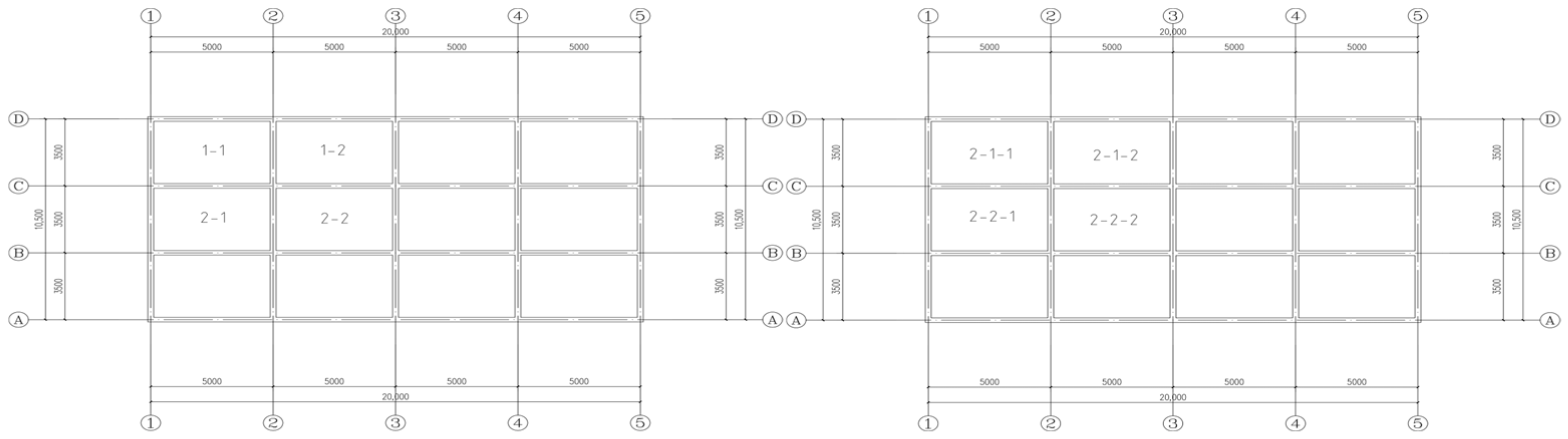
2.2. Model Parameters

This study involved the construction of a two-layer, eight-zone standard fire scenario, grounded in fire engineering principles, while accounting for the diffusion of hot smoke and the protective function of fireproof coatings. The steel frame analysis model employs a detailed modeling method with the specific parameters outlined below.
This work presents a double-layer steel frame analysis model using a horizontal configuration of four spans (5 m each span) and a vertical arrangement of three spans (3.5 m each span), with a height of 3 m (structural layout illustrated in Figure 1). Beam and column components are constructed from Q235B steel, with the following section specifications: longitudinal main beam H400 × 200 × 8 × 13, transverse main beam H400 × 200 × 8 × 13, and square steel column section H200 × 200 × 10. The Chinese standard GB50009-2012 [28] Code for Load on Building Structures specifies a constant load of 4.5 kN/m2 and a uniformly distributed live load of 2.5 kN/m2, excluding wind and snow loads from the calculation.
This model employs the solid unit modeling approach within ABAQUS software, with the material properties defined as Q235B steel. The optimal element size of 50 mm for the C3D8T element was established through grid sensitivity analysis. The beam-column joints were connected rigidly using tie constraints. The setup for the analysis step comprises two stages [29]. The static loading stage involves a time step of 1 s, utilized to precisely apply a constant load of 4.5 kN/m2 and a uniformly distributed live load of 2.5 kN/m2 to the structural system. The Thermo-Mechanical Coupling Theory employs a time step of 90 min and utilizes a temperature-displacement coupling algorithm to simulate the fire heating process. The selection criteria for fireproof coating, as outlined in the Chinese standard GB51249-2017 Technical Code for Fire Prevention of Building Steel Structures, include the use of lightweight fireproof coatings with a density of ≤600 kg/m3. The equivalent thermal resistance is specified as 0.2 m2·°C/W, corresponding to a section shape factor of 100 Fi/V. Adjustments to the thermal parameters of the material are necessary to modify the standard temperature curve for the application of fireproof materials to the structure. The internal force of the structure is determined using PKPM 2021 software for reinforcement design, with the calculation results serving as boundary conditions for ABAQUS nonlinear analysis to ensure alignment between the numerical model and design specifications.
This study examined the coupling mechanism between the thermal smoke diffusion effect and fireproof coating concerning the continuous collapse resistance of steel frames. It emphasizes the thermal deformation response of primary steel beams and columns while disregarding the secondary effects of floors and secondary beams. The thermal analysis of various rooms featuring distinct layers of steel frame structures subjected to fire was conducted. The sequential thermal coupling analysis method quantifies the temperature gradient transfer of localized fire to the entire structure.
In research concerning hot-pressure-driven ventilation mechanisms, Sedaghatkish et al. [30] developed a thermodynamic model for large caves, concluding that when a high-rise cave possesses a single narrow entrance, the ventilation process is primarily governed by the Bernoulli effect resulting from wind pressure differences. The primary ventilation mechanism in the multi-entrance cave system is the chimney effect, which arises from the differential air density between the interior and exterior of the cave. This finding closely resembles the migration of hot smoke in high-rise building fires. Choi et al.’s research [31] indicates that the chimney effect in high-rise buildings is primarily driven by buoyancy flow resulting from temperature differences between indoor and outdoor environments. In fire conditions, hot smoke penetrates the building beneath the medium-high neutral plane and exits from the region above the neutral plane. Ventilation conditions significantly influence smoke propagation modes. In buildings with properly functioning mechanical ventilation systems, the ratio of horizontal diffusion rate to vertical rise rate of smoke can reach 1:3, contrasting sharply with the nearly isotropic propagation mode observed in natural ventilation scenarios [32].

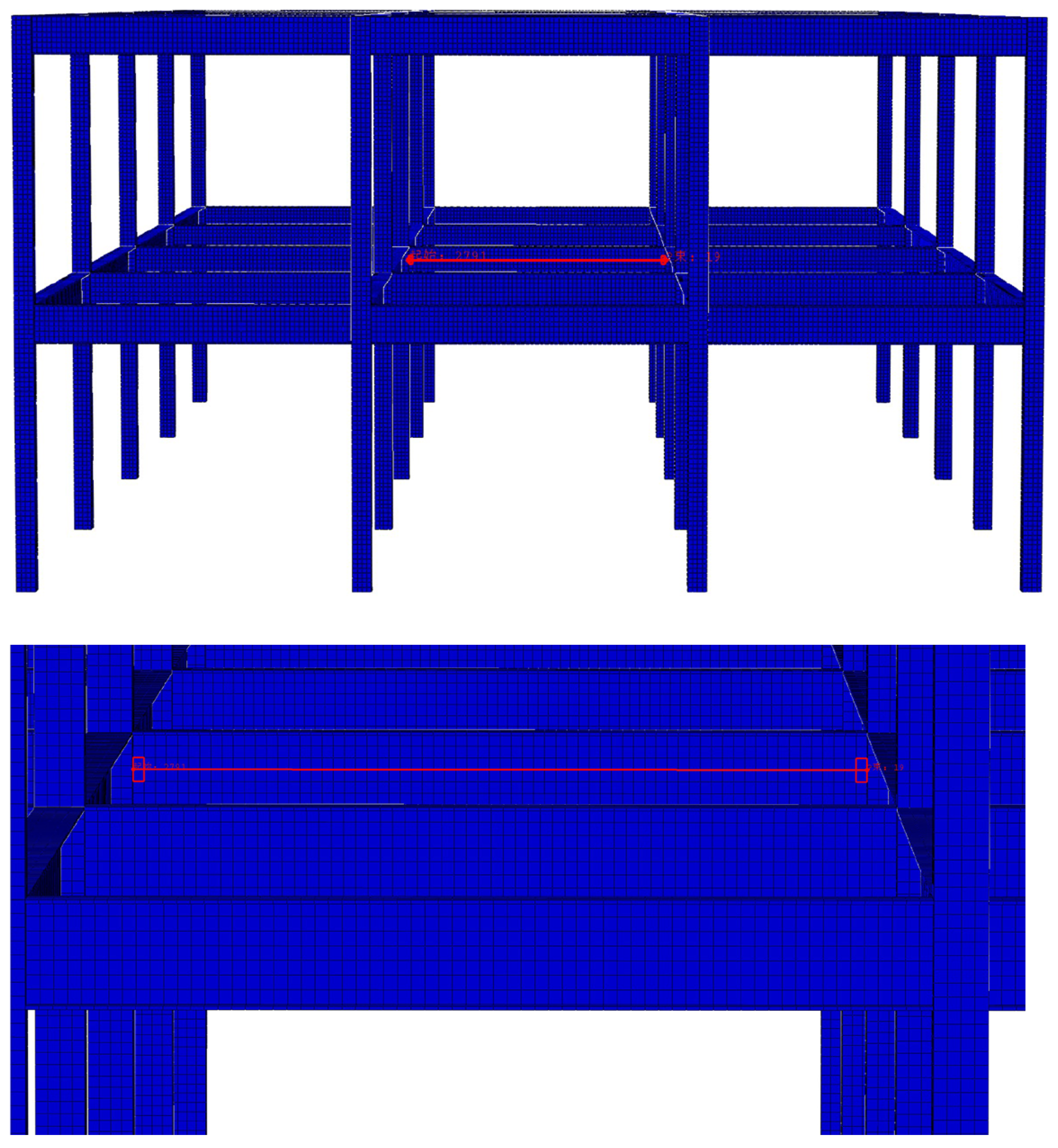
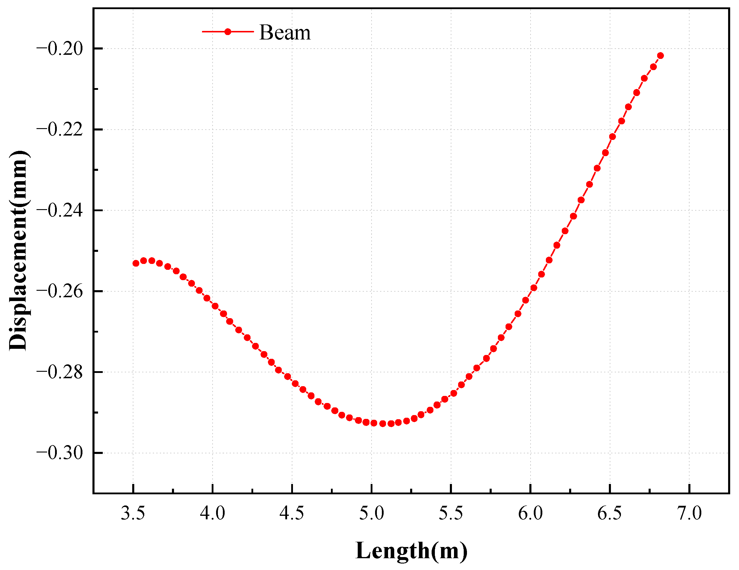
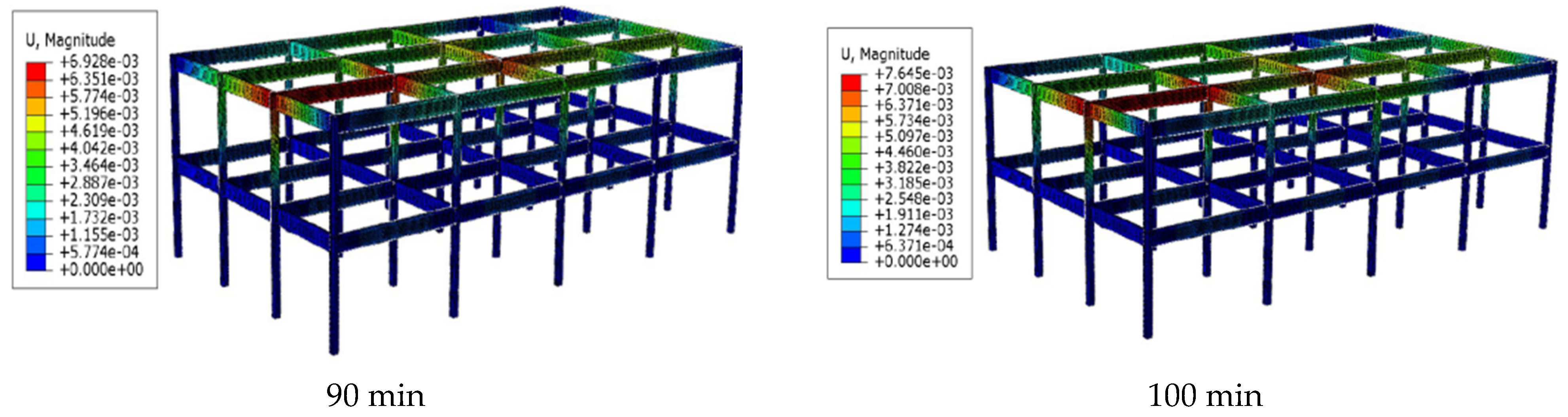
2.3. Finite Element Model Validation

The classic two-storey and four-span flat steel frame fire test conducted by Tian and Chen [33] was chosen as the verification basis for this study. Figure 2 illustrates the refined finite element model developed using ABAQUS. C3D8T cells facilitated grid division, and explicit dynamic analysis steps enabled sequential temperature-displacement coupling calculations, with temperature field data imported via user-defined field variables.
Figure 3 presents a comparison of the displacement and temperature curves at the top of the column, illustrating a high degree of consistency between the experimental and simulation results throughout the temperature rise process. The displacement deviations at critical temperature nodes (300 °C, 600 °C, and 900 °C) were below 4.2%, adhering to the permissible error threshold for numerical verification as specified in the ASCE 41-17 standard [34] (≤5%). The discrepancy arises primarily from the boundary conditions of the test. In the experimental setup, the base is secured to the test bench using anchor bolts, which may allow for minor movement, whereas the finite element model employs ideal solid connection constraints. Despite this, the displacement evolutions of the two models during the plastic development stage (400–800 °C range) demonstrate strong consistencies, thereby validating the reliability of the thermodynamic coupling modeling method presented in this paper. This verification system confirms that the sequential thermodynamic coupling algorithm utilized in this study accurately captures the entire process of stiffness degradation, plastic hinge formation, and continuous collapse of steel frames under fire, thereby establishing a theoretical foundation for subsequent parametric analysis.

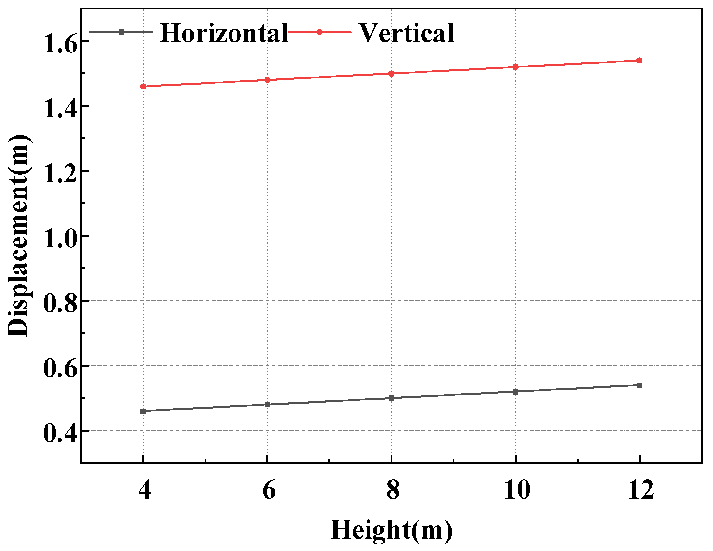
2.4. Damageability Analysis Method

Currently, Jiang et al. [35] posit that structures frequently encounter various accidental loads; thus, mitigating their vulnerability to progressive collapse can significantly enhance their resistance to such loads. Huang and Wang [36] suggested that a more detailed quantitative evaluation method is necessary to assess the continuous collapse resistance of steel frame structures, specifically focusing on their vulnerability. This paper employs the maximum displacement pair as a quantitative index to characterize the structural failure mode. This study analyzes the impact of hot flue gas propagation on the vulnerability of steel frame structures, considering the degree of deformation. The effects of hot flue gas on the steel structure are evaluated, and the corresponding improvement measures are proposed to enhance the structure’s resistance to continuous collapse. Liu and Liu [37] posit that the maximum displacement of a structure can delineate its failure state and serve as an indicator of its resistance to progressive collapse. The mechanical and deformation properties of steel-concrete structures, as presented in Table 3, are indicative of the failure modes of the components, thereby illustrating the structural failure state. An increase in the displacement of the member correlates with a decrease in the structure’s resistance to progressive collapse under accidental loads.
This study established a vulnerability analysis model for steel structures, utilizing the maximum displacement vulnerability calculation method proposed by Liu and Liu [37] and focusing on the deformation capacity of components. Figure 4 illustrates that the mid-span position of C to B along beam axis 3 (first floor, with the span length direction indicated in red) has been designated as the monitoring point for vertical displacement. The structural response analysis indicates (Figure 5) that the maximum vertical displacement of the transverse flexural load-bearing member is observed at the mid-span section, which is, therefore, considered a critical parameter for subsequent vulnerability calculations.
Cai et al. [38] categorized the limit states of structural capacity under fire conditions into two hierarchical levels: component-level and structural-level failures. Specifically, component-level failure corresponds to localized damage, manifesting as a loss of load-bearing capacity with an infinite deformation rate. In contrast, structural-level failure represents a global instability characterized by excessive deformation, rendering the structure unfit for further loading. Cai et al. proposed that the failure states of both components and the overall structure can be determined by analyzing the displacement and rate of change for lateral and vertical bending members. This provides a basis for assessing fire resistance limits. Building on Cai et al.’s formulation, this study incorporates innovative modifications to the existing methodology, advancing vulnerability parameter studies for steel structures under fire conditions in Table 4. These advancements offer a theoretical foundation for further investigations into component-level damageability in fire scenarios.
The formula and parameters related to vulnerability are as follows.
The maximum deflection and deformation rate of laterally loaded bending members are shown in Equations (4) and (5) as follows:
δ1: L2/30,000 h = 1.96
1/dt: L2/80,000 h = 0.96
When vertical load-bearing components reach their fire resistance limit, the maximum vertical displacement and its deformation rate are shown in Equations (6) and (7).
δ 2 : H / 1000 = 3
d δ 2 / d t : H / 3000 = 1
α 1 : δ L δ 1 δ 1   ξ 1 ξ 1 0   δ L δ 1 < 0 0.5   δ L δ 1 > 0
α 2 :   d δ L / d t d δ 1 / d t d δ 1 / d t   ξ 2 ξ 2 0   δ L δ 1 < 0 0.5   δ L δ 1 > 0
β 1 : δ V δ 2 δ 2 ξ 1 ξ 1 0   δ V δ 2 < 0 0.5   δ V δ 2 > 0
β 2 : d δ V / d t d δ 2 / d t d δ V / d t   ξ 2 ξ 2 0   δ V δ 2 < 0 0.5   δ V δ 2 > 0
Ζ = 0.3 ( α 1 + α 2 ) + 0.7 ( β 1 + β 2 )
In these formulas, the following is true:
  • t: time, min;
  • h: cross-sectional height, mm;
  • L: calculation span, mm;
  • H: initial fire height of the component, mm;
  • δ 1 : the absolute value of the maximum displacement when the laterally bent member reaches the fire resistance limit;
  • δ L : the absolute value of the maximum displacement reached by the laterally bent member during a fire;
  • δ 2 : the absolute value of the maximum vertical displacement when vertical load-bearing components reach the fire resistance limit;
  • δ V : the absolute value of the maximum vertical displacement reached by vertical load-bearing components during a fire;
  • d δ 1 /dt: the maximum deformation rate when the laterally bent member reaches its fire resistance limit;
  • d δ L /dt: the maximum deformation rate of a laterally loaded member during a fire.
  • d δ 2 /dt: the maximum vertical displacement deformation rate when the vertical load-bearing component reaches the fire resistance limit;
  • d δ V /dt: the maximum vertical displacement deformation rate when the vertical load-bearing component reaches the fire resistance limit;
  • ξ 1 : displacement correction factor,
  • ξ 2 : displacement rate correction factor;
  • α 1 β 1 : displacement vulnerability,
  • α 2 β 2 : repair displacement rate vulnerability;
  • Ζ: the ultimate vulnerability of the Z steel structure.

3. Analysis Results

3.1. Fire Temperature Rise Without Considering the Spread of Hot Smoke

3.1.1. Displacements and Deformation Rates of Bending Components

In this scenario, only the single compartment is subjected to fire exposure without considering the thermal smoke propagation’s influence on overall temperature rise. Figure 6a,b illustrates the vertical displacements of the steel structure’s lateral flexural members, with the y-axis representing displacement (positive upwards) and the x-axis indicating time. Figure 6c,d depicts their deformation rates, where the y-axis shows the deformation rate (positive upwards), and the x-axis indicates time.
From Figure 6a, it can be observed that the structural corner condition (Case 1-1) exhibits the largest vertical displacements, with a peak of 7.11 mm. This is due to the reduced external stiffness constraints at the corners, resulting in greater deformation compared with interior compartments. The displacements for Cases 1-2 and 2-1 are 74.6% and 73.8% of Case 1-1, respectively. Case 1-2’s displacement slightly exceeds that of Case 2-1, indicating that longer-span longitudinal beams experience greater deformation. Case 2-2 exhibits only 35.3% of Case 1-1’s displacement, demonstrating that the central compartment, with its greater columnar constraints, undergoes less deformation, distributing its impact more evenly across adjacent compartments.
Figure 6b shows that the deformation of the second-story structure is similar to that of the first story but slightly less pronounced.
Figure 6c reveals that Case 1-1 has the highest deformation rate among all four scenarios, peaking at 0.14 mm/min. Cases 1-2 and 2-1 achieve 65.2% and 67.3% of this peak rate, respectively. Case 2-2 reaches only 31.4% of Case 1-1’s rate, with its peak attained around the 60 min mark, later than Cases 1-1, 1-2, and 2-1. This reflects the slower deformation rate at the centrally constrained Case 2-2.
Figure 6d indicates that the second story’s deformation characteristics mirror those of the first story but with a lower displacement peak achieved at a later time.

3.1.2. Displacement and Deformation Rate of Load-Bearing Components

With thermal smoke spread still excluded, this analysis focuses solely on individual compartment temperature rises. Figure 7a,b illustrates the vertical displacements of vertical load-bearing members, while Figure 7c,d depict their deformation rates.
Figure 7a shows that Case 2-2 exhibits the smallest displacement, reaching only 17.2% of Case 1-1. Compared with Figure 6a, it is evident that the peak vertical displacements of flexural members exceed those of load-bearing columns, consistent with the “strong column, weak beam” design principle. This ensures that columns retain their load-carrying capacity longer than beams, preventing premature collapse.
Figure 7b indicates that the deformation pattern of the second-story structure resembles that of the first story but is less pronounced. This is attributed to the greater deformation in the first story due to vertical loads from the second story.
Figure 7c demonstrates that the deformation rate curves of load-bearing columns closely resemble those of flexural members, with slightly lower peaks.
According to the analysis in Table 5, under conditions without thermal smoke propagation, the probabilities of progressive collapse for Cases 1-1, 2-1, and 2-1-1 are relatively low. For the remaining cases, the likelihood of such an event is negligible or virtually non-existent.

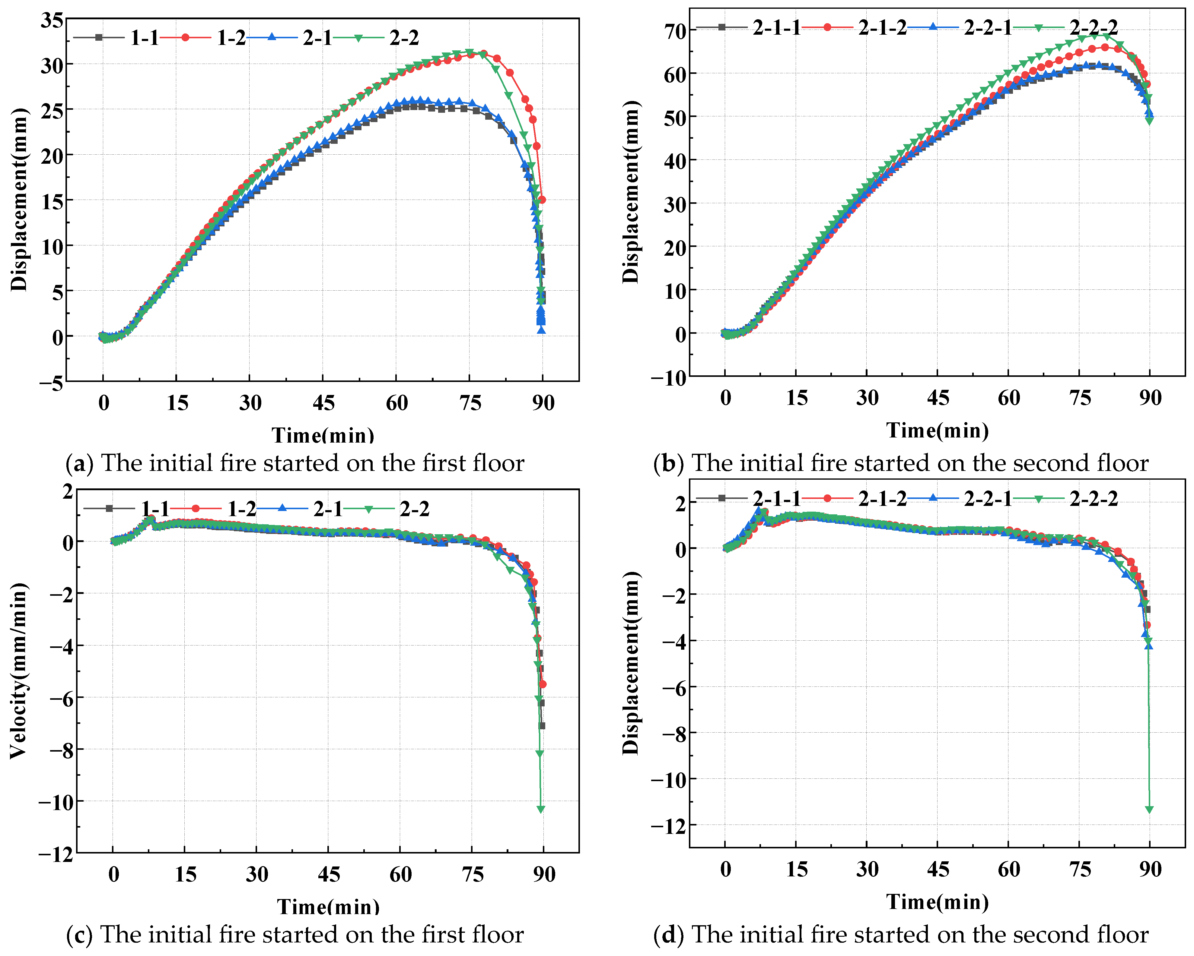
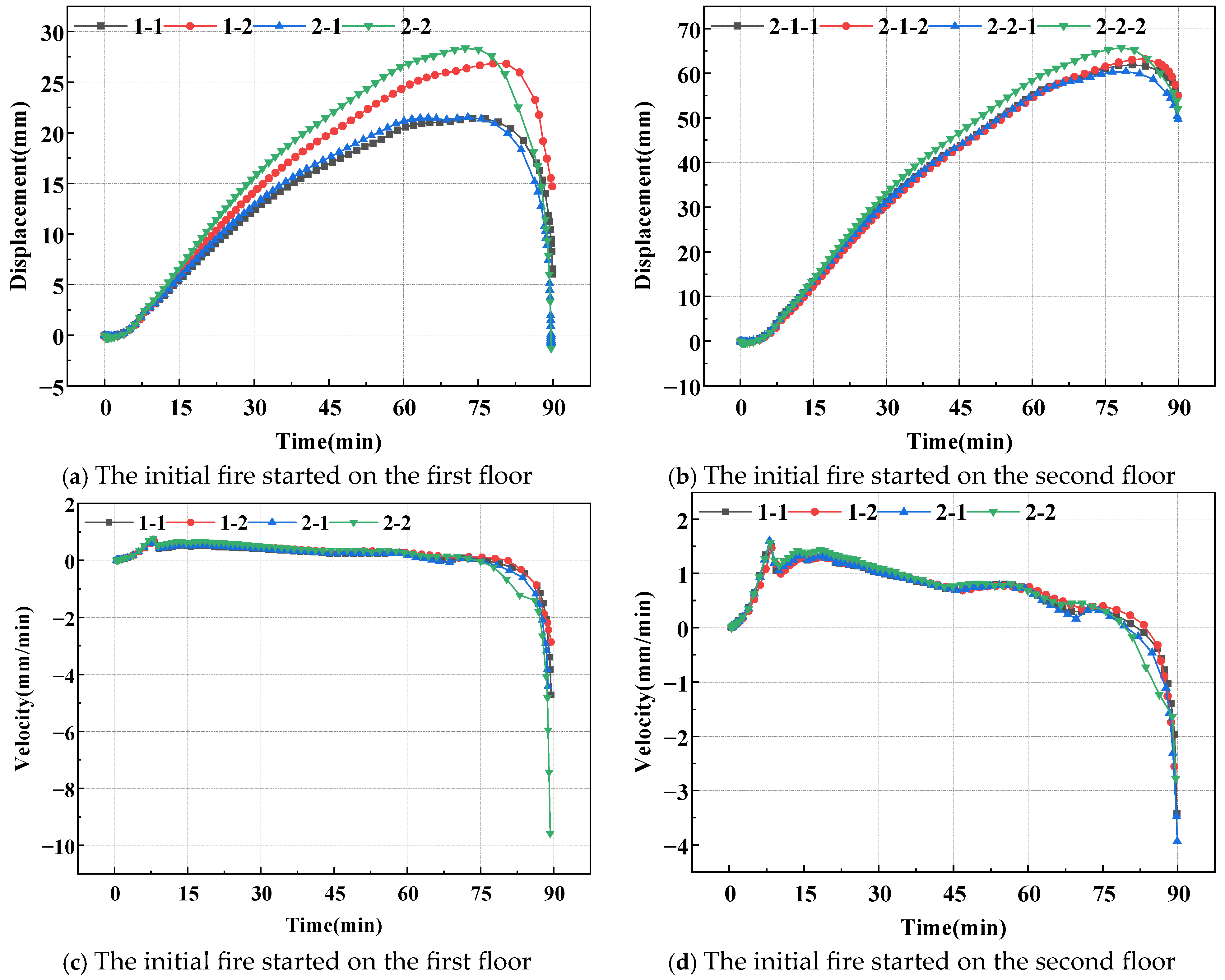
3.2. Fire Temperature Rise Considering the Steel Structure Under Hot Smoke Propagation

3.2.1. Displacements and Deformation Rates of Bending Components

Under scenarios where thermal smoke propagation significantly impacts overall temperature rise, Figure 8a,b illustrates the vertical displacement of lateral flexural members, while Figure 8c,d depict their deformation rates.
Figure 8a reveals that, under thermal smoke propagation scenarios, the displacement peaks of all conditions are tenfold compared with those without smoke spread. Among these, Case 2-2 exhibits the largest displacement. This is attributed to the rapid spread of thermal smoke from the central compartment, leading to a faster overall temperature rise. In contrast, Case 1-1, situated at the corner, experiences a prolonged thermal smoke propagation, resulting in a slower temperature increase.
Figure 8b shows that the second-story displacement peaks are double those of the first story. This is because thermal smoke from the upper level can directly propagate to other floors, accelerating the overall temperature rise.
From Figure 8c,d, it is evident that the deformation rate curves of the first and second stories are similar. At the 84 min mark, the deformation rate undergoes a significant increase, posing a heightened risk of progressive collapse.

3.2.2. Displacements and Deformation Rates of Load-Bearing Components

Under thermal smoke propagation conditions, Figure 9a,b depict the vertical displacements of load-bearing members, while Figure 9c,d detail their deformation rates.
As shown in Figure 9a–d, the deformation and rate curves of lateral flexural members closely resemble those of load-bearing columns. Both sets of members exhibit consistent displacement trends, with the structure showing noticeable yielding at the 84 min mark.
According to the analysis in Table 6, under conditions involving thermal smoke propagation, the probabilities of progressive collapse for Cases 1-1 and 2-1 remain relatively low. However, the risk is significantly higher for the remaining scenarios.

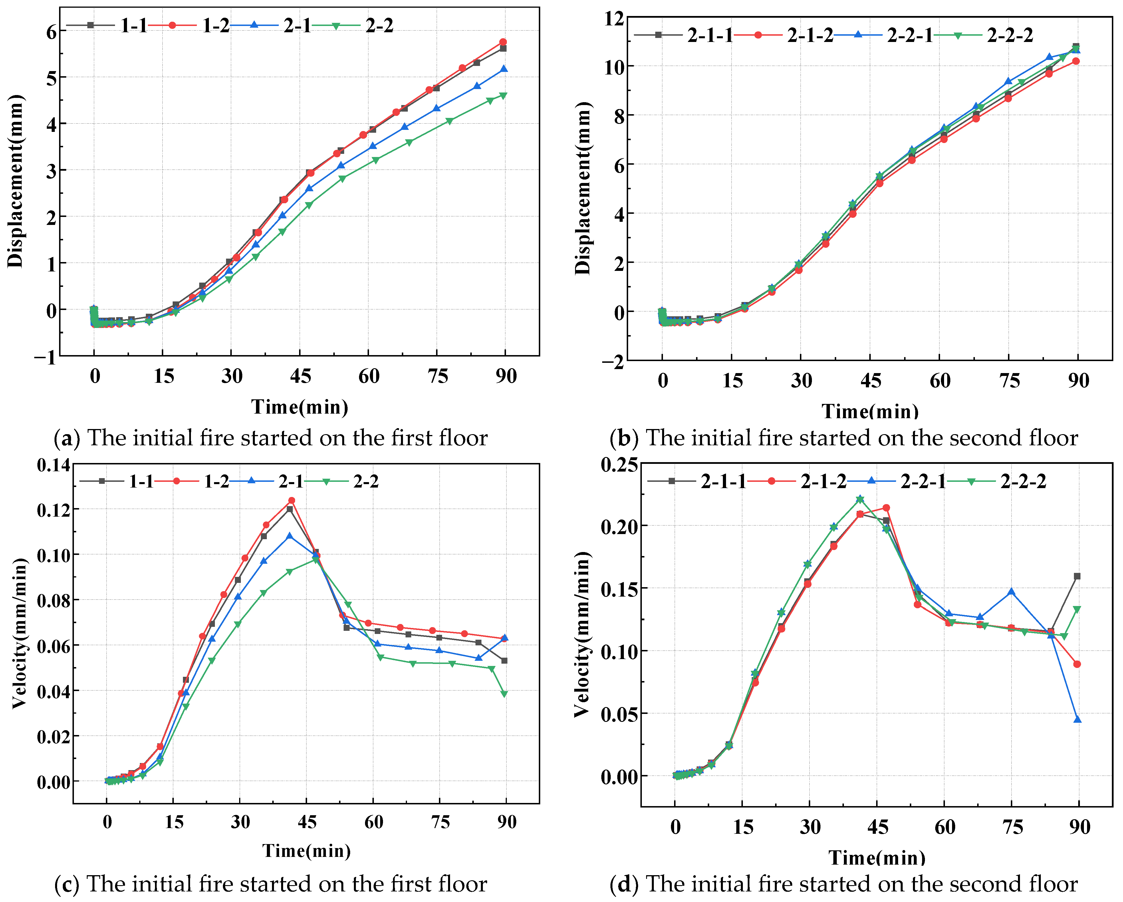
3.3. The Impact of Fireproof Coatings on Steel Structure

3.3.1. Displacements and Deformation Rates of Bending Components

Figure 10a,b presents the vertical displacement of lateral flexural members under fire scenarios with and without fireproof coatings. Figure 10c,d illustrates their deformation rates.
Figure 10a,b clearly illustrates that, with fireproof coating, the peak vertical displacements of lateral flexural members are reduced to one-sixth of those observed in naked conditions. The curves show upward trends, indicating that the structure is still undergoing thermal expansion and has yet to reach its yield stage, significantly delaying the time to failure. This underscores the enhanced fire resistance provided by fireproof coatings.
Figure 10c,d demonstrates that the maximum deformation rate with fireproof coating peaks at one-hundredth of the rate observed without coating, effectively slowing down the deformation process. This mitigation significantly reduces the risk of progressive collapse under fire conditions, thereby enhancing structural stability.

3.3.2. Displacements and Deformation Rates of Load-Bearing Components

Under the influence of thermal smoke propagation and with a fireproof coating applied, Figure 11a,b illustrates the vertical displacements of load-bearing columns, while Figure 11c,d depict their deformation rates. This section explores how fireproof coatings mitigate thermal damage despite the adverse effects of thermal smoke spread.
Figure 11a,b reveal that the application of fireproof coating reduces the vertical displacement peaks of load-bearing members to one-sixth of those observed in non-coated scenarios. This indicates that the coating significantly delays the time to yield, potentially increasing the available reaction time during emergencies.
Figure 11c,d shows that the deformation rate curves of load-bearing members closely resemble those of lateral flexural members, with substantially reduced rates when fireproof coatings are applied. This underscores the significant role of fireproof coatings in mitigating the risk of progressive collapse under fire conditions.
As analyzed in Table 7, the application of fireproof coatings drastically reduces the risk of progressive collapse for Cases 1-1 and 2-1 to almost zero. For Cases 1-2 and 2-2, while some risk remains, it is significantly lower than non-coated scenarios. However, upper-story conditions still pose a higher risk, indicating the need for additional protective measures in multi-story structures.

4. Verification of Vulnerability Formula Validity

According to the comparison study in Table 5, Table 6 and Table 7, the application of fireproof coatings greatly decreased the vulnerability characteristics. The working situation (2-2-2) is chosen as the analysis object.
When hot flue gas propagation is not taken into consideration, continuous collapse does not occur after 90 min under operating conditions (2-2-2) from Figure 12, and collapse is still not conceivable after 100 min. Under the (2-2-2) scenario from Figure 13, no visible collapse occurred within 90 min, but substantial, persistent collapse occurred after 92 min. After applying fireproof paint, the operating condition (2-2-2) did not collapse considerably before 90 min from Figure 14, and there was still no possibility after 100 min. The preceding demonstrates the correctness of Equation (12), which appropriately predicts the continuing collapse risk of a steel building under fire. Compared with Cai et al.’s vulnerability formula [38], the revised vulnerability formula increases the accuracy of forecasting the continuous collapse of steel frames by 29.1%.

5. Discussion

The study of the failure mechanism of steel frame structures in fire conditions focuses primarily on two aspects: experimental analysis and numerical modeling. The typical experimental approach (high-temperature furnace test) makes it difficult to model the dynamic interaction between components due to the high labor and financial costs. The structural design technique based on numerical simulation efficiently overcomes these constraints and has gained widespread acceptance in engineering. In this work, a thermodynamic coupling numerical model of the steel frame structure was built using ABAQUS, and the following scenarios were carefully analyzed.
  • Material thermodynamic reaction: In a fire, homogenous steel components heat up quickly but unevenly. The temperature differential of the beam web in the next fire compartment is between 180 and 250 °C. Asymmetric heating on both sides of the web results in increased deflection of the freely expanding beam and axial compressive stress of the restricted beam. According to the time-dependent study, beam deflection grows exponentially as the fire exposure time increases;
  • Structural reaction in the absence of smoke propagation: Corner chambers reveal significant deformations in beams and columns. The longitudinal beam has a greater deflection than the transverse beam due to its longer span. Due to decreased limitations, the outer column deforms 23.6% more than the inner column. The firing interval has a substantial impact on the span along the short axis. When the deflection exceeds the allowed limit, the secondary beam firmly attached to the fire-damaged longitudinal beam would bend and collapse. Because of the reduced limitations, the center column deformation is less (58% of the corner column);
  • Thermomechanical effects and smoke propagation: The center fireproof compartment transfers heat and smoke more quickly than the corner compartment, driving the total structure to the steel’s critical softening temperature. Because of the inter-story chimney effect, the buoyancy-driven air flow at the second-story fire source accelerated the smoke upward, resulting in a 96% higher column top displacement than the first-story fire scenario;
  • Comparison of fire protection technology: The expanding covering is lightweight and adaptable to complicated geometry, but it requires rigorous environmental control. Fire panels provide more environmental compatibility, but they take up more area and impose structural pressures. Both approaches minimize deformation rate and peak value while increasing fire resistance;
  • Smoke toxicity and occupant safety: Modern building fires emit poisonous vapors, including CO2, CO, H2O, SO2, CH4, CnHm, and other chemicals. Synthetic polymers in furniture and décor add to the complexity and toxicity of gasses. The enhanced smoke exhaust design can increase the safety evacuation time by 30 s while reducing casualties.

6. Conclusions

This paper established a finite element model using ABAQUS, with experimental verification of its validity. This study examined the temperature increases of steel structures under three fire scenarios: without accounting for hot flue gas propagation, with hot flue gas propagation considered, and with the application of fire-retardant coatings. This study analyzed the displacements and velocities of flexural and load-bearing members under various working conditions, deriving the corresponding parameters using the vulnerability formula. The effectiveness of the vulnerability formula was verified by comparing the results of the working condition (2-2-2) across three cases.
The conclusions are presented below.
  • The displacements of components fail to align with actual conditions when hot smoke propagation is disregarded. The consideration of hot smoke propagation resulted in a 342.3% increase in component displacement and a 561.4% increase in the displacement rate of components compared with scenarios where hot smoke propagation is not accounted for, aligning with real-world conditions;
  • The spreads of fire and hot smoke indicate that varying initial fire locations will influence the degree of deformation of the overall structure. The displacement of components in the room with the initial fire as the center increased by 23.1% compared with the components in the corner room, while the displacement in the room on the second floor increased by 115.6% compared with the components on the first floor. Therefore, it is essential to enhance fire prevention measures in the central room;
  • The application of fireproof coating markedly diminishes the displacement of components due to the spread of hot smoke, achieving a reduction of 82.8% in displacement for components located in the same position. Consequently, the use of fireproof coating mitigates structural deformation and lowers the risk of progressive collapse;
  • The improved vulnerability quantification formula enhances the accuracy of predicting the continuous collapse of the steel frame by 29.1% compared with predictions based solely on the displacement of the component;
  • The limitations of experimental conditions indicate that further exploration is required regarding the influence of hot smoke propagation on steel structures in fire scenarios.

Author Contributions

Data curation, Y.X.; Software, Y.X.; Validation, Y.X.; Visualization, Y.X. Writing—original draft, Y.X.; Investigation, J.J., Y.X. and C.K.; Project administration, J.J. and C.K.; Supervision, J.J. and C.K.; Writing—review and editing, J.J. and C.K.; Methodology, J.J. and C.K.; Resources, J.J. and C.K. All authors have read and agreed to the published version of the manuscript.

Funding

This research received no external funding.

Data Availability Statement

Data cannot be disclosed due to privacy.

Conflicts of Interest

The authors declare no conflicts of interest.

References

  1. Azim, I.; Yang, J.; Bhatta, S.; Wang, F.; Liu, Q.-f. Factors influencing the progressive collapse resistance of RC frame structures. J. Build. Eng. 2020, 27, 100986. [Google Scholar] [CrossRef]
  2. Wang, F.; Yang, J.; Wang, X.; Azim, I. Study on progressive collapse behaviour of steel-framed substructures with sheathed CFS stud infill walls. J. Build. Eng. 2021, 42, 102720. [Google Scholar] [CrossRef]
  3. Zhang, C.; Shu, J.; Zhang, H.; Ning, Y.; Yu, Y. Estimation of load-carrying capacity of cracked RC beams using 3D digital twin model integrated with point clouds and images. Eng. Struct. 2024, 310, 118126. [Google Scholar] [CrossRef]
  4. Yuan, X. Study on Smoke Transport and Dispersion Characteristics of Apartment Shaft Fire. Master’s Thesis, Liaoning Technical University, Liaoning, China, 2021. [Google Scholar]
  5. Sun, G.; Xiao, S.; Wu, J.; Xue, S. Study on mechanical properties of large-span spatial structures under large-space fire: Review and outlook. J. Build. Eng. 2024, 98, 111421. [Google Scholar]
  6. Chen, W.; Ye, J. The most adverse fire scenario research of steel frame structure fire-resistant design based on structural vulnerability analysis. Structures 2021, 34, 2861–2875. [Google Scholar]
  7. Zhai, C.; Li, J.; Xing, J.; An, X.; Zhang, W.; Yang, R. A promising strategy for enhancing fire resistance of steel structure: A composite thermoplastic polyurethane sheet adhered to steel plate. Chem. Eng. J. 2024, 488, 150689. [Google Scholar]
  8. Zhang, J.; Guo, Y.; Shao, W.; Xiao, F.J.C.; Materials, B. Benign design of intumescent fire protection coatings for steel structures containing biomass humic acid as carbon source. Constr. Build. Mater. 2023, 409, 134001. [Google Scholar] [CrossRef]
  9. Wang, G.; Yang, J. Influences of binder on fire protection and anticorrosion properties of intumescent fire resistive coating for steel structure. Surf. Coat. Technol. 2010, 204, 1186–1192. [Google Scholar] [CrossRef]
  10. Zhan, W.; Chen, L.; Gu, Z.Z.; Jiang, J.C. Influence of graphene on fire protection of intumescent fire retardant coating for steel structure. Energy Rep. 2020, 6, 693–697. [Google Scholar] [CrossRef]
  11. Dong, H.; Zhang, R.; Fan, W. Experimental study on smoke diffusion from corridors to large open spaces. Fire Sci. 1995, (S1), 60–66. [Google Scholar]
  12. Tao, L.; Wu, H.; Wang, J.; Li, B.; Wang, X.; Ning, P. Bayer process red mud for flue gas desulfurization: Influencing factors and mechanism. J. Cent. South Univ. 2019, 26, 467–478. [Google Scholar] [CrossRef]
  13. Xie, M.; Xu, F.B.; Wang, Z.D.; Yin, L.E.; Wu, X.D.; Xu, M.Q.; Li, X. Investigating fire collapse early warning systems for portal frames. Buildings 2025, 15, 296. [Google Scholar] [CrossRef]
  14. ISO 834; Fire Resistance Tests—Elements of Building Construction. International Organization for Standardization: London, Britain, 2014.
  15. Cai, G.; Zheng, X.; Gao, W.; Guo, J. Self-extinction characteristics of fire extinguishing induced by nitrogen injection rescue in an enclosed urban utility tunnel. Case Stud. Therm. Eng. 2024, 59, 104478. [Google Scholar] [CrossRef]
  16. Wang, J.; Fan, W. Numerical simulation of the fire process in a multi-room building. J. Univ. Sci. Technol. China 1996, 2, 204–209. [Google Scholar]
  17. John, A.; Podila, K.; Chen, Q.; Rao, Y. Application of high-fidelity modelling approach to predict smoke and fire propagation in a nuclear fire scenario. Therm. Sci. Eng. Prog. 2021, 23, 100903. [Google Scholar] [CrossRef]
  18. Hou, S.; Zhang, B.; Xing, L.; Chen, T.; Klymenko, O.V. 3D modelling and turbulence analysis of multiple pool fires: Capturing synergistic effects and identifying optimal models. Int. J. Therm. Sci. 2025, 210, 109652. [Google Scholar] [CrossRef]
  19. Helfenstein, R.P.; Lemmertz, C.K.; Centeno, F.R. The impact of fire source location on hot gas layer temperature in multi-compartment pre-flashover fires: Analysis and semi-empirical model development. Int. J. Therm. Sci. 2025, 208, 109464. [Google Scholar] [CrossRef]
  20. Wei, X.; Liu, J.; Xu, L. Intelligent prediction method for the collapse time of steel frame structures under fire. J. Constr. Steel Res. 2024, 219, 108798. [Google Scholar]
  21. Argenti, F.; Landucci, G. Experimental and numerical methodology for the analysis of fireproofing materials. J. Loss Prev. Process Ind. 2014, 28, 60–71. [Google Scholar] [CrossRef]
  22. Ji, J.; Nie, J.K.; Zhu, H.; Han, Y.; Liu, H.; Wang, X.M. Experimental analysis of intumescence fireproofing coating on base material of substation frames. Case Stud. Therm. Eng. 2024, 64, 105478. [Google Scholar] [CrossRef]
  23. Ma, X.M.; Pan, J.L.; Cai, J.M.; Zhang, Z.Y.; Han, J.S. A review on cement-based materials used in steel structures as fireproof coating. Constr. Build. Mater. 2022, 315, 125623. [Google Scholar]
  24. GB 50017-2017; Code for Design of Steel Structures. China Architecture & Building Press: Beijing, China, 2017.
  25. Li, W.C.; Ge, B.T.; Li, Z.P.; Xing, G.H.; Jing, Y. Post-fire mechanical properties and constitutive model of Q690 high-strength structural steel. Eng. Fail. Anal. 2024, 160, 108232. [Google Scholar] [CrossRef]
  26. Li, X.H.; Zhang, S.Y.; Yang, X.C.; Guo, Z.M.; Li, Z.J.; Xu, X.L. Air temperature characteristics of cable-girder pin joint node of suspension bridge under pool fire. Structures 2024, 69, 107354. [Google Scholar]
  27. EU3; Bijlaard, F. Eurocode 3: Design of steel structures–Present status and further developments. Steel Constr. Des. Res. 2008, 1, 16–23. [Google Scholar]
  28. GB50009-2012; Code for Load on Building Structures. China Architecture & Building Press: Beijing, China, 2012.
  29. Wang, H.; Yang, B.; Zhou, X.H.; Kang, S.B. Numerical analyses on steel beams with fin-plate connections subjected to impact loads. J. Constr. Steel Res. 2016, 124, 101–112. [Google Scholar]
  30. Sedaghatkish, A.; Pastore, C.; Doumenc, F.; Jeannin, P.Y.; Luetscher, M. Thermal modeling of caves ventilated by chimney effect. Int. J. Therm. Sci. 2025, 212, 109757. [Google Scholar]
  31. Choi, Y.; Yang, S.; Kim, S. The smoke control system to improve the possibility of evacuation from fire disasters in high-rise buildings. Therm. Sci. Eng. Prog. 2025, 59, 103269. [Google Scholar] [CrossRef]
  32. Xu, Z. Study on Somke Temperature and Velocity in the Stairwell with Differnent Opening Conditions. Master’s Thesis, University of Science and Technology of China, Hefei, China, 2010. [Google Scholar]
  33. Tian, X.M.; Chen, S.C. Numerical simulation of fire response and failure mechanism of multi-story steel structures. J. Disaster Prev. Mitig. Eng. 2012, 32, 59–63. [Google Scholar]
  34. ASCE 41-17; Seismic Evaluation and Retrofit of Existing Buildings. American Society of Civil Engineers: Reston, VA, USA, 2017.
  35. Jiang, J.; Cao, Y.F.; Zhang, Q.J. Research progress on quantitative evaluation methods for structural robustness. Prog. Steel Build. Struct. 2022, 24, 1–21. [Google Scholar]
  36. Huang, J.Z.; Wang, Z. Evaluation method for robustness of steel frame structures. J. Civ. Eng. 2012, 45, 46–54. [Google Scholar]
  37. Liu, Y.B.; Liu, J.B. Damageability analysis of steel-concrete composite frame structures. In Proceedings of the 17th National Conference on Structural Engineering; Tsinghua University Press: Beijing, China, 2008; Volume II. [Google Scholar]
  38. Cai, X.J.; Jiang, W.J.; Mao, X.Y.; Shi, Z.T. Damageability analysis of multi-story steel frames under post-earthquake fire based on fire load density. J. Disaster Prev. Mitig. Eng. 2022, 42, 269–275. [Google Scholar]
Figure 1. Ichnography.
Buildings 15 01128 g001
Figure 2. Horizontal and vertical speeds.
Buildings 15 01128 g002
Figure 3. Structural displacements in experiments and simulations.
Buildings 15 01128 g003
Figure 4. First layer along axis 3 direction C to B beams.
Buildings 15 01128 g004
Figure 5. Vertical displacements along the length of the beam.
Buildings 15 01128 g005
Figure 6. Displacement and velocity changes of lateral components at different initial fire locations.
Buildings 15 01128 g006
Figure 7. Displacement and velocity changes of vertical components at different initial fire locations.
Buildings 15 01128 g007
Figure 8. Displacement and velocity changes of lateral components at different initial fire locations.
Buildings 15 01128 g008
Figure 9. Displacement and velocity changes of vertical components at different initial fire locations.
Buildings 15 01128 g009
Figure 10. Displacement and velocity changes of lateral components at different initial fire locations.
Buildings 15 01128 g010
Figure 11. Displacement and velocity changes of vertical components at different initial fire locations.
Buildings 15 01128 g011
Figure 12. Displacements and deformations without heat flue gas propagation.
Buildings 15 01128 g012
Figure 13. Displacements and deformations of hot flue gas propagation.
Buildings 15 01128 g013
Figure 14. Displacements and deformations by adding fireproof paint.
Buildings 15 01128 g014
Table 1. Physical parameters of steel at high temperature.
ArgumentDensity
ρs
Specific Heat Capacity
Cs
Poisson’s Ratio
Vs
Coefficient of Thermal Expansion
ɑs
Coefficient of Heat Conduction
λs
Unitkg/m3J/(kg·°C)-m/(m·°C)W/(m °C)
Data78506000.31.4 × 10−545
Table 2. Constitutive model in European specification EC3.
Strain RangeStress: σTangent Modulus
ε < ε p T ε E T E T
ε p T < ε < ε y T f p T C + ( b / a ) [ a 2 ( ε y T ε ) 2 ] 0.5 b ( ε y T ε ) a [ a 2 ( ε y T ε ) 2 ] 0.5
ε p T < ε < ε y T f y T 0
ε y T < ε < ε t T f y T [1 − (ε − ε f T )(− ε u T ε f T )]-
ε = ε u T 0-
In the table: ε p T = f p T E T , ε y T = 0.02, ε t T = 0.15   , ε u T   = 0.20, a = ( ε y T ε p T ) ( ε y T ε p T + c / E T ) , b = c ( ε y T ε p T ) E T + c 2 , c = ( f y T f p T ) 2 ( ε y T ε p T ) E T 2 ( f y T f p T ) , where ε p T : the proportional limit strain at T temperature; ε t T : the maximum strain of yield strength at T temperature; ε u T : the ultimate strain at T temperature; f y T : the yield strength at T temperature; f p T : the yield strength at T temperature; E T : the initial elastic modulus at temperature T.
Table 3. Classification of structural failure modes based on the maximum displacements.
Destruction StatusMaximum Displacement (mm)
Basically intact D m a x < 129
Minor damage129 D m a x < 360
Moderate damage 360 D m a x < 590
Severe damage 590 D m a x < 947
Complete destruction D m a x 947
Table 4. Classification of the possibility of continuous collapse based on the vulnerability parameters.
The Possibility of a Continuous Collapse OccurringVulnerability Parameters
Basically impossible Ζ 0
Very small possibility 0 < Ζ 1
Smaller possibility 1 < Ζ 10
Higher possibility Ζ > 10
Table 5. Peak lateral and vertical displacements, displacement rates, and related parameters for various cases.
CasePeak Lateral Displacement/
10−3 m
Peak Lateral Displacement Rate/
10−3 m/min
Vertical
Displacement Peak/
10−3 m
Vertical
Displacement Rate Peak/
10−3 m/min
α 1 α 2 β 1 β 2 Ζ
1-17.110.1415.790.1182.63−0.8530.930−0.882−0.566
1-25.310.0924.620.0921.71−0.9040.540−0.908−0.016
2-15.250.0955.320.1071.68−0.9010.773−0.893−0.149
2-22.510.0441.000.0220.28−0.954−0.667−0.978−1.350
2-1-17.000.1235.950.1242.57−0.8720.983−0.8760.585
2-1-23.910.0713.650.0740.99−0.9260.217−0.926−0.476
2-2-13.890.0653.800.0720.98−0.9320.267−0.928−0.447
2-2-23.110.0582.410.0450.58−0.940−0.197−0.955−0.912
Table 6. Peak lateral and vertical displacements, displacement rates, and related parameters for various cases under conditions involving thermal smoke propagation.
CasePeak Lateral Displacement/
10−3 m
Peak Lateral Displacement Rate/
10−3 m/min
Vertical
Displacement Peak/
10−3 m
Vertical
Displacement Rate Peak/
10−3 m/min
α 1 α 2 β 1 β 2 Ζ
1-125.2−7.112.14−4.7111.90−8.416.13−5.711.33
1-231.0−5.5126.8−2.8714.80−6.747.93−3.875.27
2-125.8−3.1221.412.2012.20−4.256.1311.2014.50
2-231.3−1.0328.313.8015.00−11.708.4312.8015.80
2-1-161.5−2.6761.83.4230.40−3.7819.602.4223.40
2-1-265.9−3.4463.12.5632.60−4.5820.001.5623.50
2-2-161.7−4.2860.33.9430.50−5.4619.102.9422.90
2-2-268.7−11.0065.72.7834.10−12.5020.901.7822.40
Table 7. Peak lateral and vertical displacements, displacement rates, and related parameters for various cases under fireproof coatings.
CasePeak Lateral Displacement/
10−3 m
Peak Lateral Displacement Rate/
10−3 m/s
Vertical
Displacement Peak/
10−3 m
Vertical
Displacement Rate Peak/
10−3 m/s
α 1 α 2 β 1 β 2 Ζ
1-15.610.1194.278.91.86−0.8760.423−0.911−0.045
1-25.750.1234.429.51.93−0.8720.473−0.905−0.016
2-15.160.1074.419.41.63−0.8890.470−0.906−0.082
2-24.610.0975.3511.41.35−0.8990.783−0.886−0.064
2-1-110.800.20810.1020.24.51−0.78323.7−0.7982.220
2-1-210.200.2149.9020.34.20−0.77723.0−0.7972.080
2-2-110.600.2209.2018.64.41−0.77120.7−0.8141.970
2-2-210.700.22010.4022.04.46−0.77124.7−0.7802.290
Disclaimer/Publisher’s Note: The statements, opinions and data contained in all publications are solely those of the individual author(s) and contributor(s) and not of MDPI and/or the editor(s). MDPI and/or the editor(s) disclaim responsibility for any injury to people or property resulting from any ideas, methods, instructions or products referred to in the content.

