Article

The Influence of the Construction of the Bridge Pile Foundation on the Adjacent Operating Subway Tunnel Considering the Creep Characteristics of the Stratum

1
School of Municipal and Transportation Engineering, Anhui Water Conservancy Technical College, Hefei 231603, China
2
School of Civil Engineering, Hefei University of Technology, Hefei 230009, China
*
Author to whom correspondence should be addressed.
Buildings 2025, 15(7), 1001; https://doi.org/10.3390/buildings15071001
Submission received: 3 February 2025 / Revised: 10 March 2025 / Accepted: 19 March 2025 / Published: 21 March 2025

Abstract

The pile foundation construction adjacent to an operational subway tunnel can induce the creep effects of the surrounding soil of the tunnel, resulting in the deformation of the existing tunnel lining and potentially compromising the safe operation of the tunnel. Therefore, the Mindlin solution and the generalized Kelvin viscoelasticity constitutive model were employed to establish the theoretical calculation model for the deformation of the adjacent subway tunnel caused by the pile construction. Then, the effect of pile construction on the deformation of adjacent tunnels under different pile–tunnel spacing was analyzed via three-dimensional numerical simulation and theoretical calculation methods and compared with the field monitoring data. The results showed that the theoretical and numerical data are in agreement with the field monitoring data. The theoretical model provides closer predictions to the field-measured values than the numerical simulation. As the distance between the pile and the tunnel increases, both the vertical settlement and the horizontal displacement of the subway tunnel lining exhibit a gradual reduction. In the hard plastic clay region of Hefei City (China), pile foundation construction near an operational subway tunnel can be classified into three distinct zones based on proximity to the tunnel: the high-impact zone (<1.0 D), the moderate-impact zone (1.0 D–3.0 D), and the low-impact zone (>3.0 D). The pile foundation in high-, moderate-, and low-impact zones should be monitored for 7 days, 3 days, and 1 day, respectively, to ensure the stable deformation of the lining.

1. Introduction

As urbanization progresses, the continuous expansion of urban areas has spurred rapid advancements in urban transportation systems and underground space engineering projects, resulting in an increasingly complex and sophisticated transportation network [1,2,3]. The concurrent development of transportation infrastructures, including urban viaducts, expressways, and subways, is particularly evident in large cities and their surrounding regions [4,5]. The density and intricacy of transportation hubs are progressively increasing. With limited space, the construction of urban viaducts in proximity to subway tunnels is becoming increasingly prevalent [6,7,8], as illustrated in Figure 1. Meanwhile, the issue of deformation impacts from pile foundation construction on adjacent operational metro tunnels has become increasingly significant. The construction of pile foundations can cause changes to the stress state and deformation of surrounding soils, potentially causing deformation in nearby operational metro tunnels. Such deformations may lead to tunnel misalignment, segment damage, water seepage, and other structural issues. In extreme cases, these problems could disrupt normal metro operations and result in substantial economic losses [9,10,11]. In addition, during the pile foundation construction near the subway, it is necessary to conduct deformation monitoring of the tunnel lining to ensure the safe operation of the subway tunnel. However, the current monitoring cycle lacks a reasonable basis and is mostly based on construction experience, with the deformation monitoring of the lining lasting for several months or even up to half a year, which will cause a huge waste of money. Thus, it is an important issue to investigate the effect of pile foundation construction on the adjacent operational metro tunnel and analyze the evolution of the lining deformation in relation to pile–tunnel spacing over time.
There have been a number of studies addressing the impact of pile excavation on nearby subway tunnels from different perspectives through simulation, experimentation, and theoretical derivation methods. Yoo [12] adopted numerical simulation methods to investigate the effect of different pile–tunnel spacing conditions. Lin et al. [9] established two finite element models about pile foundation construction on existing metro tunnels and discovered that as the distance between the pile foundation and the metro tunnel increases, the degree of influence decreases. Lueprasert [13] simulated the whole process of pile excavation and proposed a construction impact zone for the new pile foundation in relation to adjacent subway tunnels. Li et al. [14] applied model experiment methods to construct three different pile–tunnel spacing cases to compare with the numerical simulation results. Yao et al. [15] employed centrifuge tests to monitor the deformation of the existing tunnel lining at pile–tunnel separation distances. At the same time, the Boussinesq solution and Mindlin solution, which are widely used as theoretical solutions in soil mechanics, have also been adopted to calculate the additional stress effects of pile foundation construction on adjacent operational subway tunnels and to analyze the influence of the position and magnitude of the pile foundation load on the deformation of the lining [16,17,18,19]. Above all, previous research works provide good guidance in the study of pile excavation nearby operational tunnels. However, most existing research on this subject regarded soil as an elastic or elastoplastic body, ignoring the viscoelastic characteristics of the cohesive soil. Creep characteristics, the time-dependent deformation of soil under sustained stress, are particularly significant in cohesive soils like clay. Even after external stress stabilizes, cohesive soils exhibit continuous deformation, which can significantly affect the long-term stability and deformation of tunnel structures. Jia et al. [20] adopted the Creep-SCLAY1S model, which can be capable of characterizing the creep behavior of clay, to simulate the vertical and horizontal displacements induced in the tunnel during the creep process. Zeng et al. [21] developed a model for stress and displacement fields around non-circular tunnels, accounting for viscoelastic rock properties and tunnel geometry. Zhang et al. [22] utilized the Boltzmann viscoelastic model to characterize the rheological behavior of the soil and analyzed the influence of clay creep characteristics on the deformation of the tunnel lining. The creep effect of cohesive soil can result in the continuous deformation of the surrounding cohesive soil around the subway tunnel even after the completion of pile foundation construction adjacent to the operational subway. The lack of analysis on the long-term disturbance effect of clay creep induced by the excavation of pile foundations near operating subways can cause inadequate control of tunnel deformation, potentially leading to issues such as tunnel cracking and water seepage.
Therefore, this study aims to investigate the viscoelastic characteristics of the cohesive soil around the operating subway and conducts a theoretical derivation model for the displacement of the tunnel caused by pile foundation excavation. The work considers a real pile construction project adjacent to a subway tunnel located in Hefei (China) as a case example. The viscoelastic constitutive model of the soil was determined through on-site creep tests. Subsequently, theoretical calculations and numerical simulation methods were adopted for analysis, and the results were compared with on-site subway monitoring data to validate the applicability and precision of the theoretical formula. Finally, a deformation prediction model for tunnel lining was developed to investigate the evolution law of lining deformation with respect to pile–tunnel spacing and time. This research can provide a theoretical foundation for pile foundation construction in proximity to tunnels in similar geological settings.

2. Engineering Background

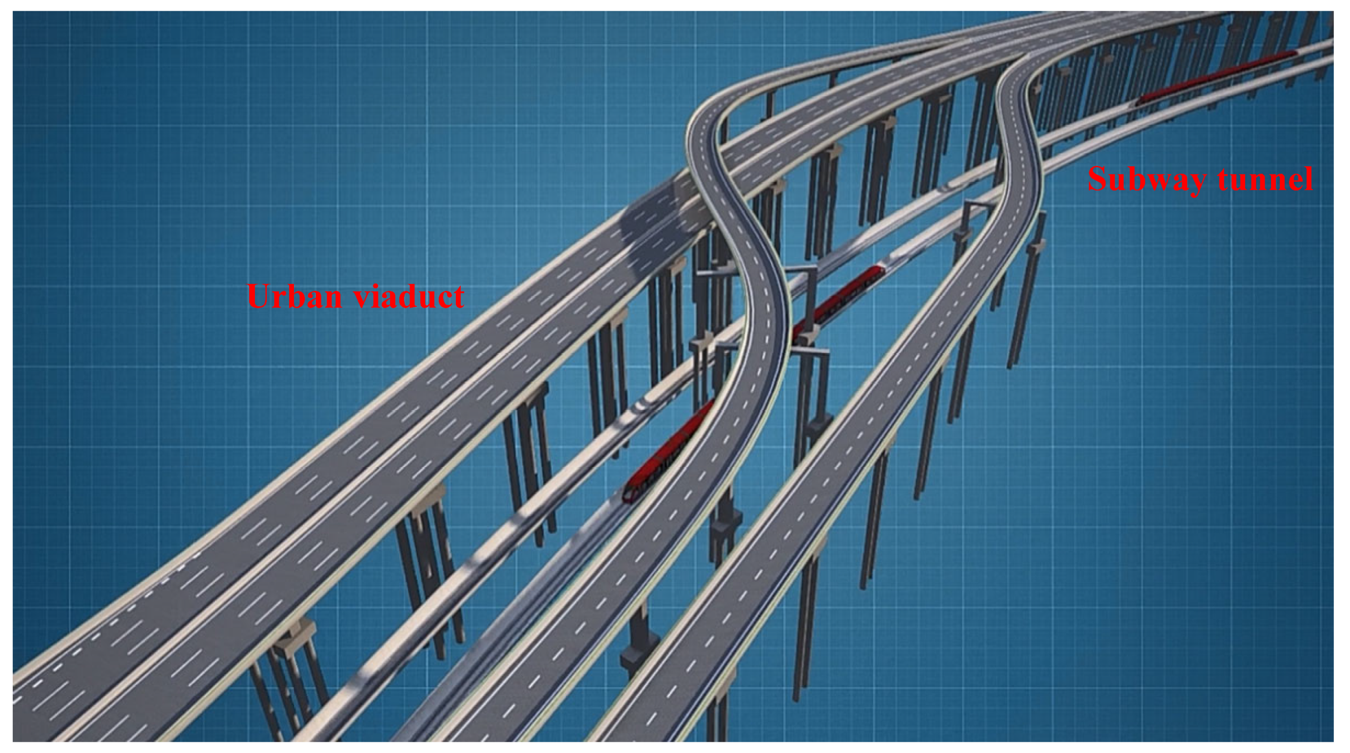
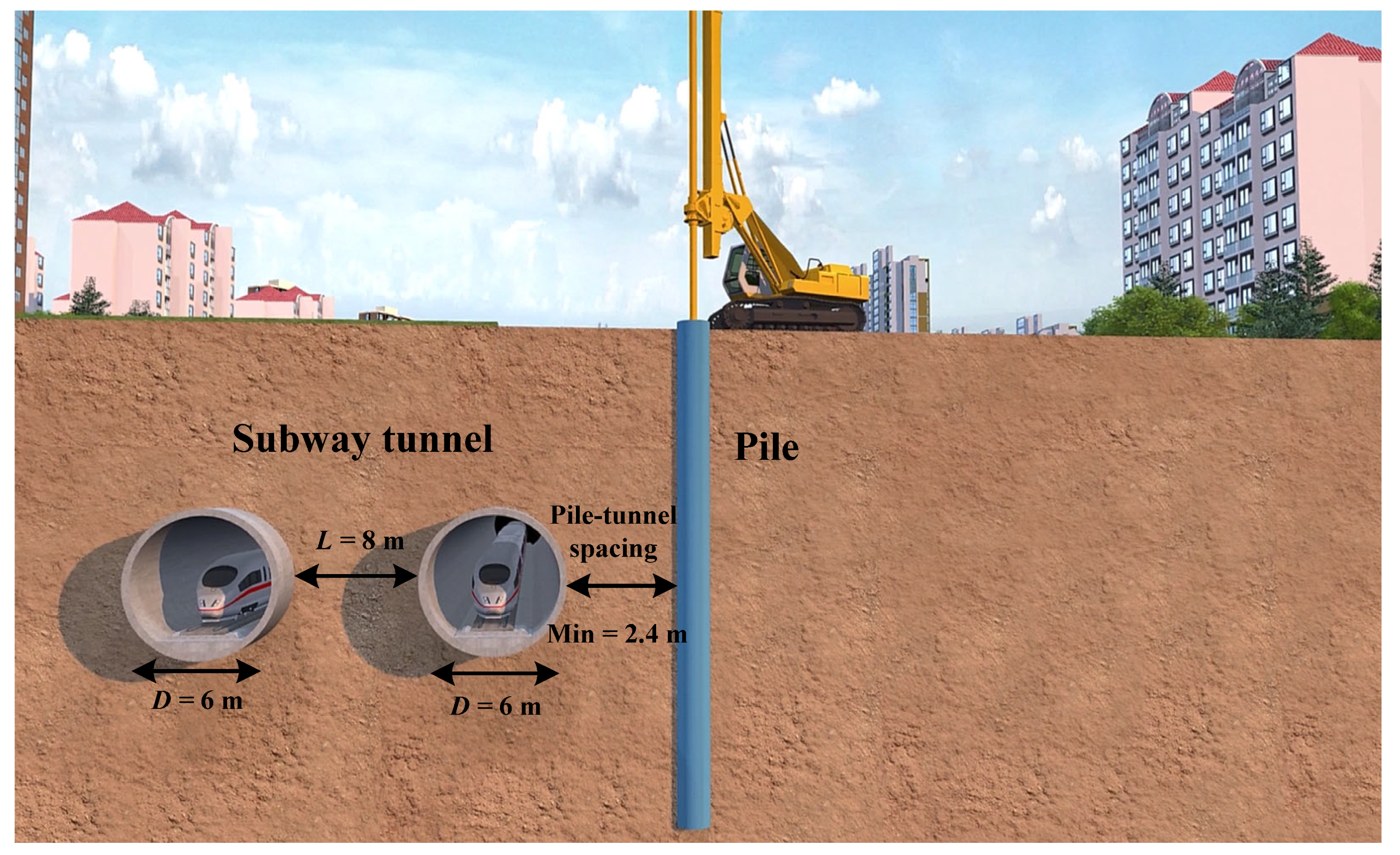
2.1. Project Overview

The double-decker elevated bridge on Wenzhong Road in Hefei city originates from the northern side of the intersection between Langxi Road and Baogong Avenue to the south, crossing over Xinhai Avenue, Tianshui Road, and Xinbianhe Road to the north, ultimately terminating at Shaoquan Street. The total length of the elevated bridge is 6.65 km, with a width of 25.5 m for the main section. The main bridge spans from K0 + 885.85 to K6 + 533.85, including a segment from K2 + 458.85 to K2 + 826.85 that runs parallel and adjacent to the completed Subway Line 3. The positional relationship between the subway tunnel and the elevated bridge is illustrated in Figure 2, where the minimum distance between the pile tunnels is approximately 2.4 m. The on-site bored pile construction was completed within one day, and the procedure is as follows: (1) drilling (6 h), (2) Rebar Cage Installation and lowering (2 h), (3) continuous concrete pouring (completed immediately after reinforcement placement), (4) concrete setting (final setting no more than 12 h), and (5) the construction of the second pile on the same foundation. The pile foundation of the elevated bridge consists of bored piles with a diameter of 1.5 m and lengths ranging from 37 to 48 m. Based on drilling data, surrounding engineering information, on-site geological mapping, in situ testing, and laboratory geotechnical test results, the geological strata within the project area primarily comprise the Quaternary Holocene artificial fill layer (Q4ml), the Quaternary Upper Pleistocene alluvial layer (Q3al), and exposed bedrock predominantly consisting of mudstone sandstone from the Upper Cretaceous Zhangqiao Formation (K2z). The Subway Line 3 tunnel traverses a stratum of yellow-brown, hard plastic clay within the alluvial deposit (Q3al).

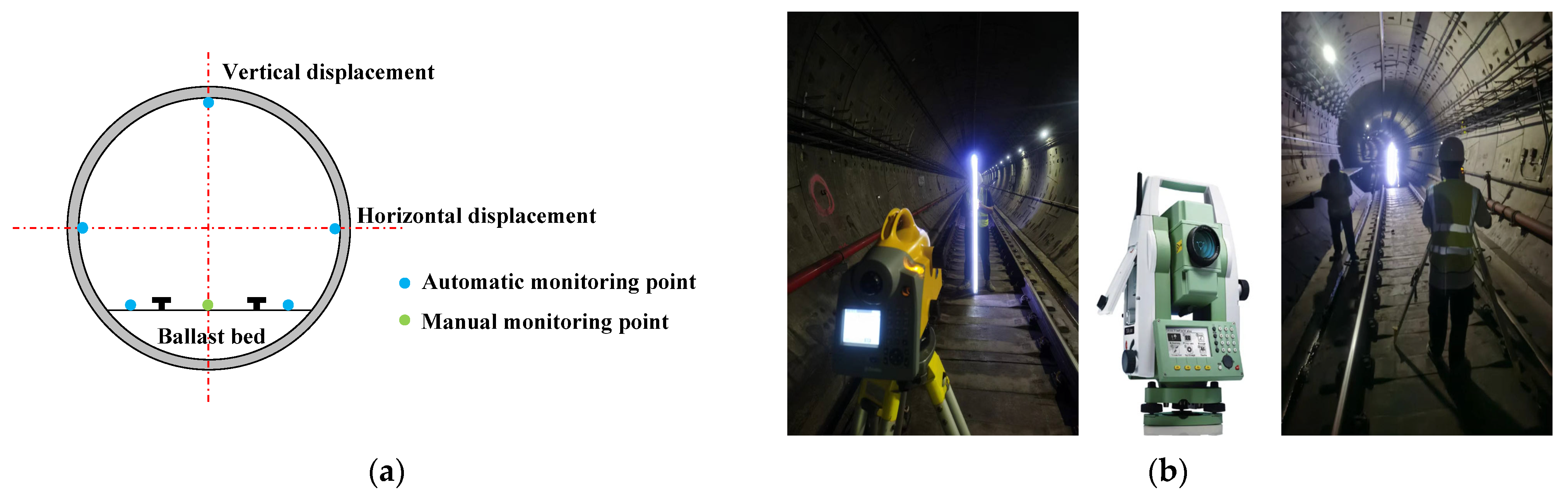
2.2. Tunnel Monitoring

The horizontal and vertical displacements of the tunnel lining structure are monitored throughout the entire construction process of the bored pile adjacent to the operating subway tunnel at varying distances from the tunnel, with the aim of preventing lining deformations induced by pile foundation excavation. An intelligent total station (Leica TM60, Leica Geosystems, München, Germany) is utilized for the automated monitoring of both tunnel horizontal convergence and tunnel clearance. The electronic level is adopted for monitoring the vertical settlement of the structure. The arrangement of the monitoring points and the on-site monitoring process are illustrated in Figure 3. The construction monitoring and control standards are established as follows: The cumulative vertical settlement or uplift displacement of the tunnel lining must not exceed 5 mm, and the rate of change must not exceed 1 mm/day. Similarly, the cumulative horizontal displacement must not exceed 5 mm, with the rate of change also limited to 1 mm/day (the Technical Code for the Protection Structures of Urban Rail Transit (CJJT 202-2013) and the Code for Monitoring Measurement of Urban Rail Transit Engineering (GB 50911-2013)) [23,24].

3. Creep Test and Model Identification

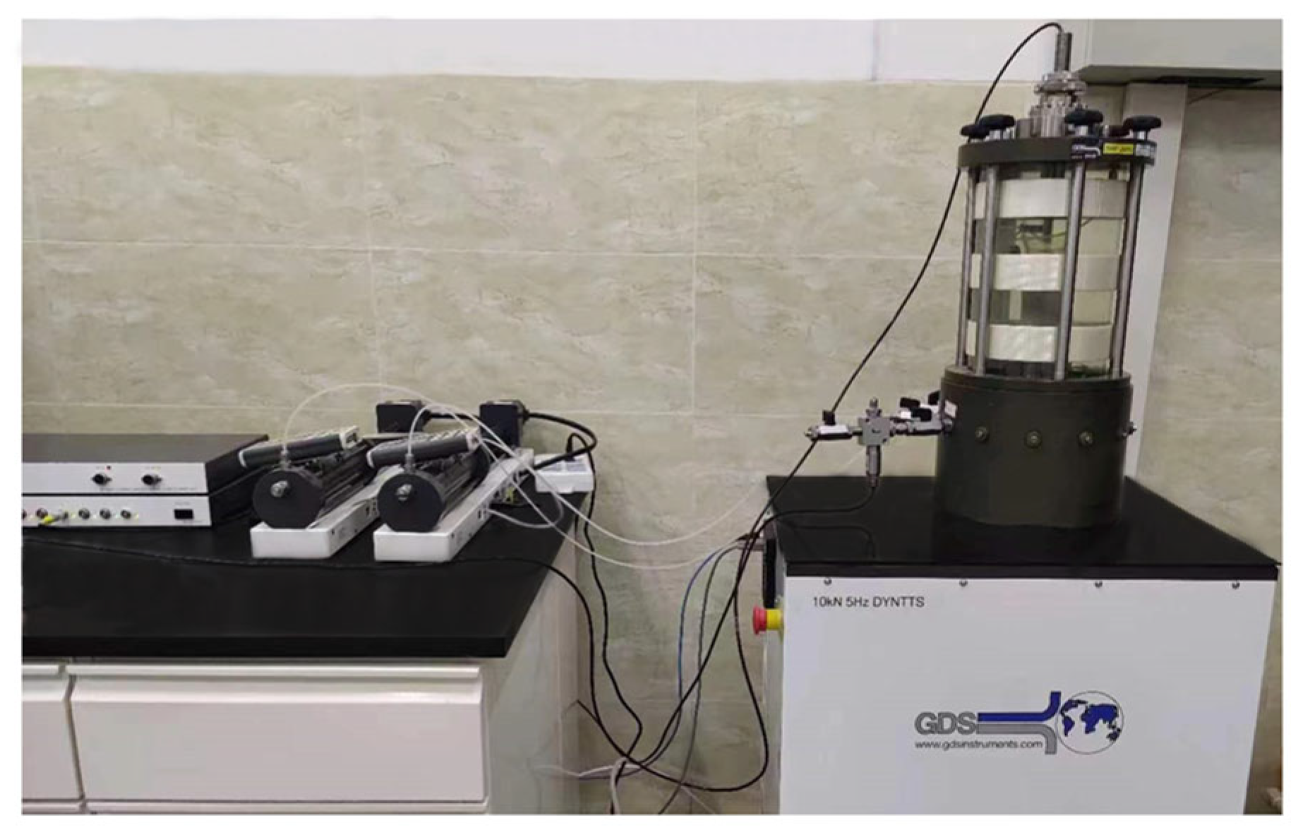
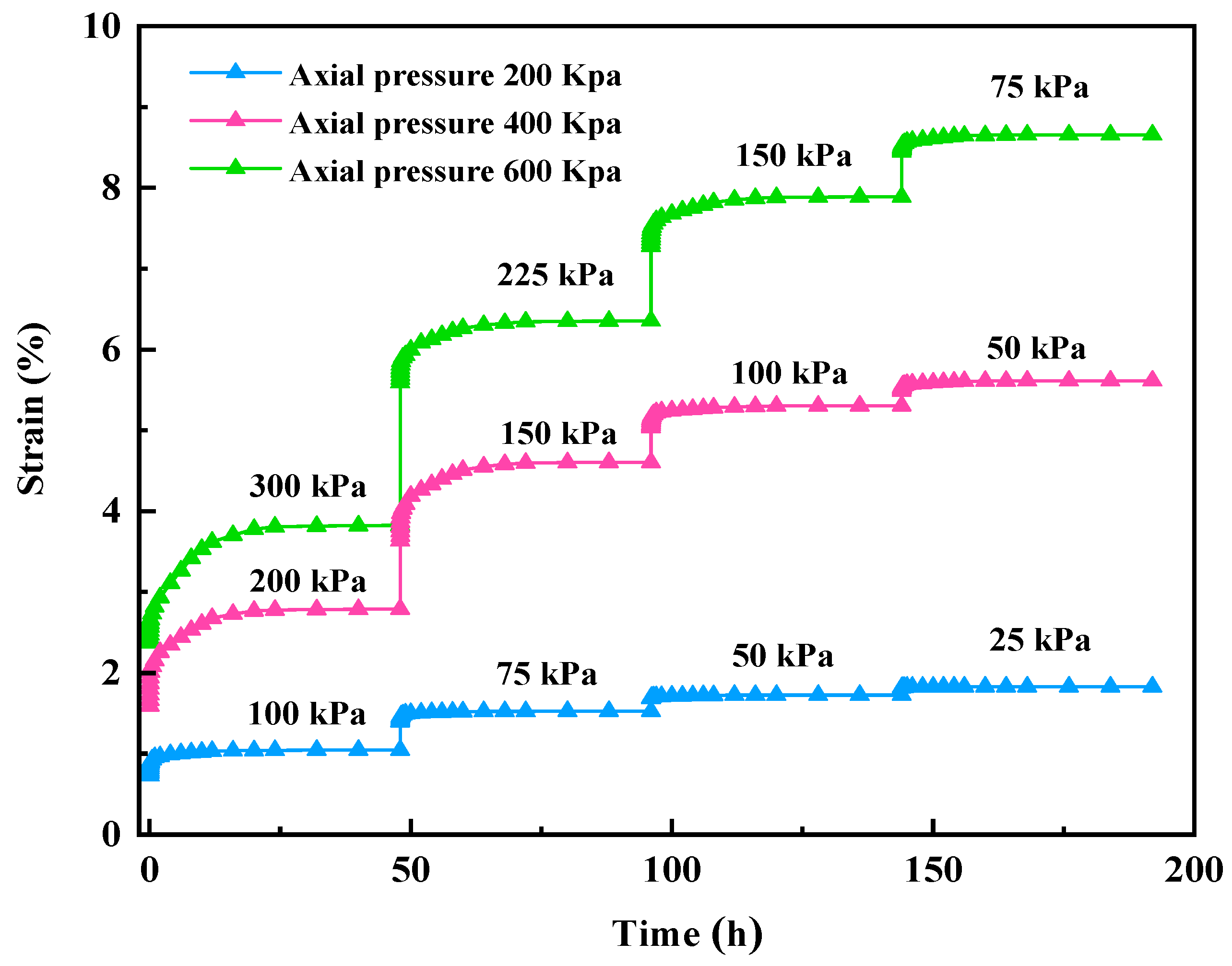
3.1. Graded Unloading Creep Test

The research object of this creep test is the yellow-brown hard plastic clay located near the Xinhai Avenue subway station, with a soil depth ranging from 10 to 20 m. Given the structural characteristics of clay, to minimize disturbance to the soil samples, a thin-walled soil sampler with a diameter of 80 mm and a length of 800 m was applied for sampling. After retrieval, the soil sample was transferred to the curing room for stabilization. The physical and mechanical properties of the soil sample are summarized in Table 1.
The experimental instrument adopted a globally distributed service (GDS) triaxial rheological testing system to conduct graded unloading creep tests (Figure 4).
The undisturbed soil sample, measuring 39.1 mm in diameter and 80 mm in height, was employed as the test specimen. This sample replicated the initial stress state of naturally deposited soil and simulated the actual excavation and unloading processes encountered during pile foundation construction. The stress state of soil at various depths is characterized to establish the appropriate axial and confining pressures for creep testing. Prior to conducting the creep test, an initial K0 anisotropic consolidation condition (where K0 represents the coefficient of lateral earth pressure at rest) is applied according to the sampling depth. The experimental results indicate that K0 is determined to be 0.5. The creep test plan is shown in Table 2. Considering the varying thickness of soil overlying the arch of the subway tunnel, three sets of creep tests were conducted at different depths. Specifically, the tests were performed under axial pressures of 200 kPa (corresponding to a depth of 10 m), 400 kPa (20 m depth), and 600 kPa (30 m depth). The creep effect of cohesive soil was investigated by continuously reducing the confining pressure through a stepwise unloading method. During this process, time, temperature, axial displacement, and water level were recorded at regular intervals. The criterion for creep stability is defined as the axial strain at 24 h being less than 1‰ to 5‰ of the total cumulative creep axial strain. Once this stability criterion is met, the confining pressure is then unloaded.

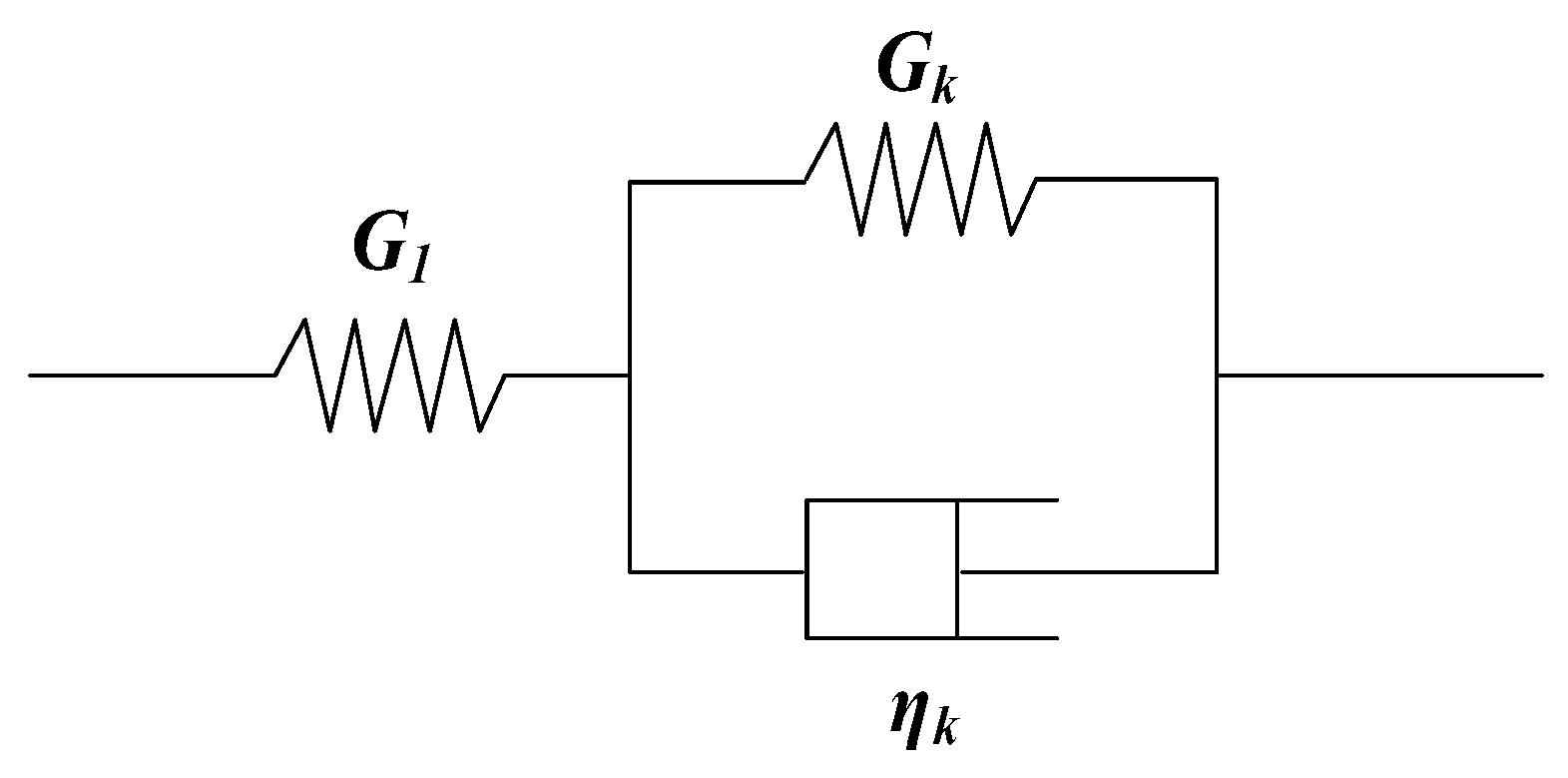
3.2. Creep Test Results and Identification of Creep Model

The creep test data were collected by the three-axis testing machine data system, and the complete process curve of soil grading unloading was obtained, as shown in Figure 5.
From Figure 5, it can be seen that: (1) After applying confining pressure and axial pressure to the soil sample, a certain amount of elastic instantaneous deformation occurs. Sample 3 is subjected to the maximum axial compression, with an instantaneous deformation of 2.4%, which is greater than that of Sample 1 and Sample 2. When the soil reaches a stable state and begins to unload the confining pressure, instantaneous deformation occurs to varying degrees. The magnitude of this instantaneous deformation decreases progressively with an increasing number of unloading cycles for each sample. (2) After the soil sample undergoes instantaneous deformation, it transitions into a state of attenuation creep, during which the strain rate progressively diminishes. Upon staged unloading of the confining pressure, the attenuation creep phase gradually diminishes. (3) When the strain rate of the specimen tends to stabilize, it enters the stable creep stage. As the confining pressure progressively decreases, specimens 1, 2, and 3 rapidly transition into the stable creep stage. The aforementioned phenomenon can be attributed to the continuous action of load. This process results in the expulsion of pore water, a reduction in the thickness of the bound water film between particles, and an increase in effective stress, and consequently, the sample becomes progressively denser. Meanwhile, during the graded unloading process of the three soil samples, creep reached the stable stage after 24 h. Taking Sample 2 as an example, under the combined action of 400 kPa axial pressure and 200 kPa confining pressure, a strain of 2.35% was generated after 4 h, and a strain of 2.68% was generated after 12 h, accounting for 96.1% of the total strain.
Based on the creep curve of the soil sample, the soil initially undergoes elastic instantaneous deformation upon pressurization, followed by a phase of decaying creep that eventually stabilizes. Consequently, the generalized Kelvin model and Burgers model are employed to characterize soil creep behavior. The generalized Kelvin model and the Burgers model were employed to fit the creep test curves of clay at the initial depths of 10 m, 20 m, and 30 m. The results are shown in Figure 6. Both the generalized Kelvin model and the Burgers model exhibit a strong capability in fitting the clay creep test data, with correlation coefficients averaging 0.950 for the generalized Kelvin model and 0.984 for the Burgers model. By observing the fitting curve in the latter half of the Burgers model, it was found that the latter half of the fitting curve is a straight line with a non-zero slope, indicating that the soil has entered the stage of constant velocity creep, and the slope values were determined to be 0.01 (600 kPa), 0.005 (400 kPa), and 0.012 (200 kPa), respectively. In other words, as time progresses, the strain of the soil sample is expected to increase. However, the experimental creep curve indicates that after 24 h, the soil sample enters a stable creep phase in which strain remains constant over time. Therefore, the Burgers model cannot accurately reflect the stable creep behavior of soil samples under the same axial pressure but different confining pressures, while the generalized Kelvin model can accurately reflect the stable creep of soil samples. The generalized Kelvin constitutive model is more suitable for describing the creep behavior of clay soil during excavation and unloading.
Using the secondary development interface of Flac3D software (version 6.0), the predefined generalized Kelvin model was compiled into a dynamic link library (DLL), integrated into the main program, and subsequently invoked during computational simulations.

4. Theoretical Analysis and Numerical Simulation

4.1. Assumption and Soil Deformation

The excavation and unloading of drilled cast-in-place piles can induce displacement and stress alterations in the surrounding soil, resulting in the deformation of adjacent operational subway tunnels. The following conditions are assumed: (1) The foundation soil can be characterized as a uniformly isotropic, continuously deformable medium, representing a semi-infinite body. (2) The tunnel experiences slight deformation. (3) The tunnel is in intimate contact with the surrounding soil, meaning that the displacement of the tunnel is directly influenced by the movement of the foundation soil. The free displacement induced by the excavation of pile foundations near subway tunnels can be addressed and calculated using the Mindlin solution [25,26,27]. The expressions for vertical and horizontal displacement solutions are as follows:
s v ( x , y , z ) = D P 0 ( 1 + v ) d x d y 8 π E ( 1 v ) 3 4 v R 1 + 8 ( 1 v ) 2 ( 3 4 v ) R 2 + ( z 0 ξ ) 2 R 1 3 + ( 3 4 v ) ( z 0 + ξ ) 2 2 z ξ R 2 3 + 6 ξ z 0 ( z 0 + ξ ) 2 R 2 5
s h ( x , y , z ) = D Q 0 ( 1 + v ) d x d y 8 π E ( 1 v ) ( 3 4 v ) R 1 + 1 R 2 x 2 R 1 3 + ( 3 4 v ) x 2 R 2 3 + 2 ξ z 0 R 2 3 1 3 x 2 R 1 2 + 4 ( 1 v ) ( 1 2 v ) R 2 + z 0 + ξ 1 x 2 R 2 R 2 + z 0 + ξ
In the formula, E is the elastic modulus of the soil, and v is the Poisson’s ratio of the soil. ζ is the excavation depth of the pile foundation, and the horizontal coordinates at that depth are given by ε, η. P0 is the vertical distributed load of the soil, and Q0 is the horizontal distributed load. P 0 = i = 1 n γ i h i . Q 0 = K 0 i = 1 n γ i h i . γi and hi are the weight and thickness of each soil layer. K0 is the lateral pressure coefficient, and z0 is the burial depth of the adjacent subway tunnels.
R 1 = ( x ε ) 2 + ( y η ) 2 + ( z ζ ) 2
R 2 = ( x ε ) 2 + ( y η ) 2 + ( z + ζ ) 2

4.2. Calculation of Viscoelastic Solutions

The generalized Kelvin constitutive model is composed of an elastic element and a Kelvin element connected in series, as shown in Figure 7. G1 denotes the initial shear modulus, Gk represents the shear modulus, and ηk signifies the viscosity coefficient.
The differential constitutive relationship of classical three-dimensional viscoelastic bodies is as follows [28]:
P S i j ( t ) = Q e i j ( t ) ; P σ k k ( t ) = Q ε i j ( t )
In the formula, Sij(t) is the deviatoric stress tensor; eij(t) is the deviatoric strain tensor; σkk(t) is the spherical stress tensor; εij(t) is the spherical strain tensor; and P′, Q′, P″, Q″ are linear differential operators. The expression is as follows:
P = k = 0 m p k d k d k t ; Q = k = 0 n q k d k d k t P = k = 0 m p k d k d k t ; Q = k = 0 n q k d k d k t
The generalized Kelvin constitutive model has the following partial tensor viscoelastic relationship and spherical tensor elastic relationship:
G 1 + G k S i j ( t ) + η k d S i j d t = 2 G 1 G k e i j ( t ) + 2 G 1 η k d e i j d t
σ k k ( t ) = 3 K ε k k ( t )
According to Equations (7) and (8), the differential operator expression in Equation (6) can be expressed as shown in Equation (9):
P = G 1 + G k + η k d d t ; Q = 2 G 1 G k + 2 G 1 η k d d t ; P = 1 ; Q = 3 K
Perform Laplace transform on Equation (9), and the expression is as follows:
P ¯ = G 1 + G k + η k d d t ; Q ¯ = 2 G 1 G k + 2 G 1 η k d d t ; P = 1 ; Q = 3 K
Since elastic materials are viscoelastic materials in the special case of ηk = 0, the tensile transformation expressions for elastic modulus E and Poisson’s ratio v are presented as follows:
E ( s ) = 3 Q ¯ ( s ) Q ¯ ( s ) 2 Q ¯ ( s ) P ¯ ( s ) + Q ¯ P ¯ ( s ) ; v ( s ) = Q ¯ ( s ) P ¯ ( s ) Q ¯ ( s ) P ¯ ( s ) 2 Q ¯ ( s ) P ¯ ( s ) + Q ¯ ( s ) P ¯ ( s )
Substituting Equation (10) into Equation (11) yields the relaxation modulus E(s) and the relaxation Poisson’s ratio v(s), which can be expressed as follows:
E ( s ) = 9 K G 1 G k + G 1 η k s 3 K G 1 + G k + η k s + G 1 G k + G 1 η k s v ( s ) = 3 K G 1 + G k + η k s 2 G 1 G k 2 G 1 η k s 6 K G 1 + G k + η k s + 2 G 1 G k + 2 G 1 η k s
According to the principle of elastic–viscoelastic correspondence for quasi-static problems, the vertical distributed load of semi-infinite viscoelastic soil is given by P(t) = P0·H(t), and the horizontal distributed load is given by Q(t) = Q0·H(t), where H(t) is the Heaviside function. After a Laplace transform is performed on P(t) and Q(t), they are substituted into Equations (1) and (2), and then, another Laplace inverse transform is performed to obtain the viscoelastic solutions for the vertical and horizontal displacements of a semi-infinite body in a generalized Kelvin viscoelastic space. The resulting expressions are as follows:
s v ( x , y , z , t ) = D P 0 d x d y 8 π z 0 ξ 2 R 1 3 2 z 0 ξ R 2 3 + 6 z ξ z 0 + ξ 2 R 2 5 A 3 + A 4 e A 6 t 1 G k e τ t 1 R 1 1 R 2 + z 0 + ξ 2 R 2 3 A 4 e A 6 t A 1 + 1 G k e τ t 8 R 2 A 5 e A 7 t A 2 + 1 4 G k e τ t
s h ( x , y , z , t ) = D Q 0 d x d y 8 π x 2 R 2 R 1 3 + 2 z 0 ξ R 2 3 1 3 x 2 R 1 2 A 3 + A 4 e A 6 t 1 G k e τ t + 1 R 1 + x 2 R 2 3 A 4 e T 6 t A 1 + 1 G k e τ t + 4 R 2 + z 0 + ζ 1 x 2 R 2 R 2 + z 0 + ζ 4 R 2 + z 0 + ζ 1 x 2 R 2 R 2 + z 0 + ζ .
In the formula,
A 1 = 7 G 1 2 G k + 3 K G 1 2 + 7 G 1 G k 2 + 6 K G 1 G k + 3 K G k 2 G 1 G k 4 G 1 G k + 3 G 1 K + 3 G k K ; A 2 = 4 G 1 2 G k + 3 K G 1 2 + 4 G 1 G k 2 + 6 K G 1 G k + 3 K G k 2 4 G 1 G k G 1 G k + 3 G 1 K + 3 G k K ; A 3 = G 1 2 G k + 3 K G 1 2 + G 1 G k 2 + 6 K G 1 G k + 3 K G k 2 G 1 G k 4 G 1 G k + 3 G 1 K + 3 G k K ; A 4 = 12 G 1 2 η k 3 K η k + 4 G 1 η k 4 G 1 G k + 3 G 1 K + 3 G k K ; A 5 = 3 G 1 2 η k 3 K η k + G 1 η k 4 G 1 G k + 12 G 1 K + 12 G k K ; A 6 = 4 G 1 G k + 3 G 1 K + 3 G k K 3 K η k + 4 G 1 K ; A 7 = G 1 G k + 3 G 1 K + 3 G k K 3 K η k + G 1 η k . A 8 = 27 K G 1 2 + 54 K G 1 G k + 27 K G k 2 2 G 1 G k + 3 G 1 K + 3 G k K 4 G 1 G k + 3 G 1 K + 3 G k K ; A 9 = 3 G 1 2 η k 3 K η k + G 1 η k 2 G 1 G k + 6 G 1 K + 6 G k K ; A 10 = G 1 G k + 3 G 1 K + 3 G k K 3 K η k + G 1 η k ; A 11 = 24 G 1 2 η k 3 K η k + 4 G 1 η k 4 G 1 G k + 3 G 1 K + 3 G k K ; A 12 = 4 G 1 G k + 3 G 1 K + 3 G k K 3 K η k + 4 G 1 η k .

4.3. Numerical Model and Parameter Determination

Numerical simulation methods are used to effectively analyze the deformation effects of pile foundation excavation on the lining of adjacent operating subway tunnels, and the accuracy and applicability of theoretical calculation models are compared and validated. Therefore, this study employs Flac3D finite difference software to simulate the impact of the entire bored pile construction process on the deformation of adjacent subway tunnel linings under varying pile–tunnel spacing conditions.
According to the on-site geotechnical investigation report and design data, the outer diameter (D) of the operating subway tunnel is 6.0 m, the inner diameter is 5.4 m, and the lining thickness is 0.3 m. The 3D numerical model of the pile–tunnel system was simplified by considering only a single pile located at varying distances from the tunnel. The strata from top to bottom consist of the plain fill layer, clay layer, and sandstone layer. As shown in Figure 8, the effect of groundwater is not considered due to the low permeability of the hard plastic clay (3 × 10⁻⁶ cm/s) surrounding the tunnel. The upper boundary of the model is defined as a free boundary, and normal constraints are applied around the perimeter and at the bottom of the model. The generalized Kelvin model is utilized to characterize the creep behavior of the clay layer post-excavation, and the Mohr–Coulomb model is employed for the sandstone. The physical and mechanical parameters of the model, as derived from the geotechnical investigation report, are shown in Table 3:
Based on the on-site data, the operating subway that excavates adjacent pile foundations primarily traverses hard plastic clay layers. The tunnel has a cover depth of approximately 21.5 m and experiences an axial pressure of 428 kPa. For the purpose of calculating the creep model parameters, the creep test curve corresponding to an axial pressure of 400 kPa is selected. The parameters for the generalized Kelvin model, used in theoretical and numerical calculations for hard plastic clay, are presented in Table 4.
The calculation simulation scheme is based on the on-site construction process, and the results were then detailed and compared with the theoretical solutions and monitoring data. According to the on-site conditions, the simulated pile–tunnel spacing ranges from 2.4 m (0.4 D) to 18.0 m (3 D).

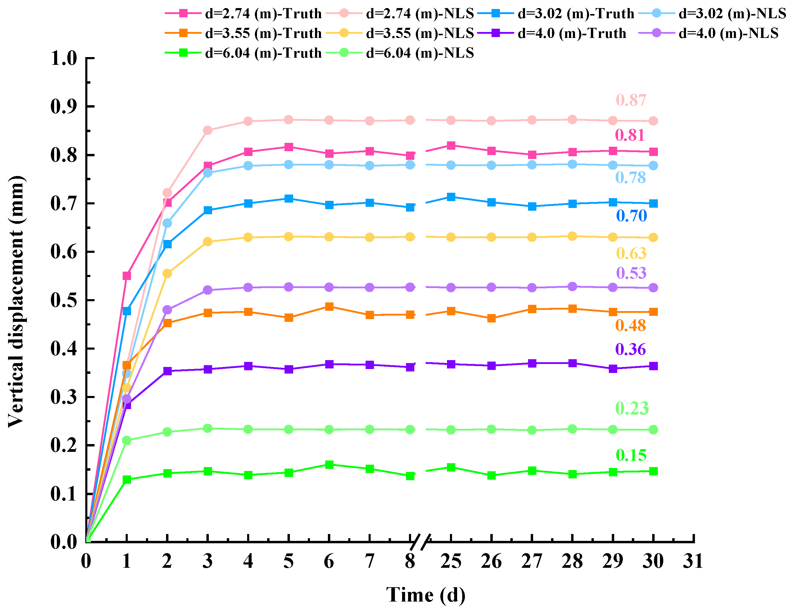
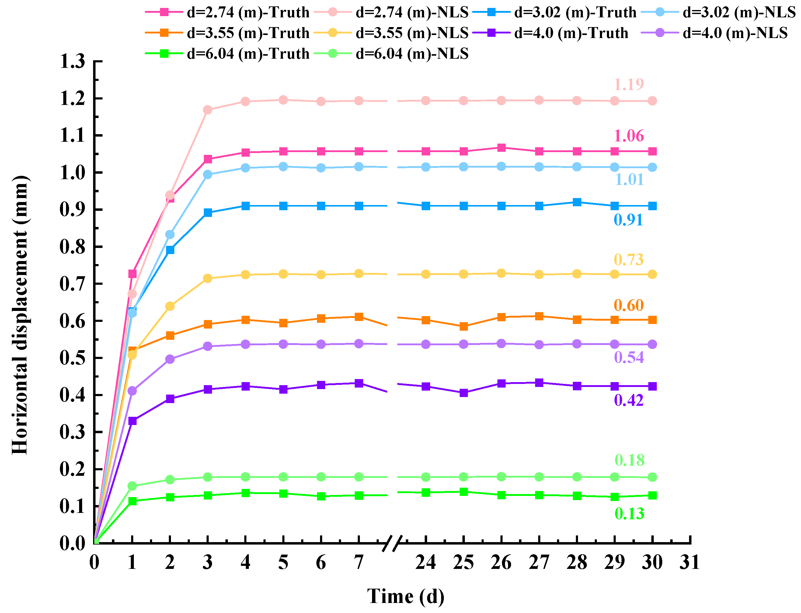
5. Comparative Analysis of Theoretical Models, Numerical Simulations, and Monitoring Data

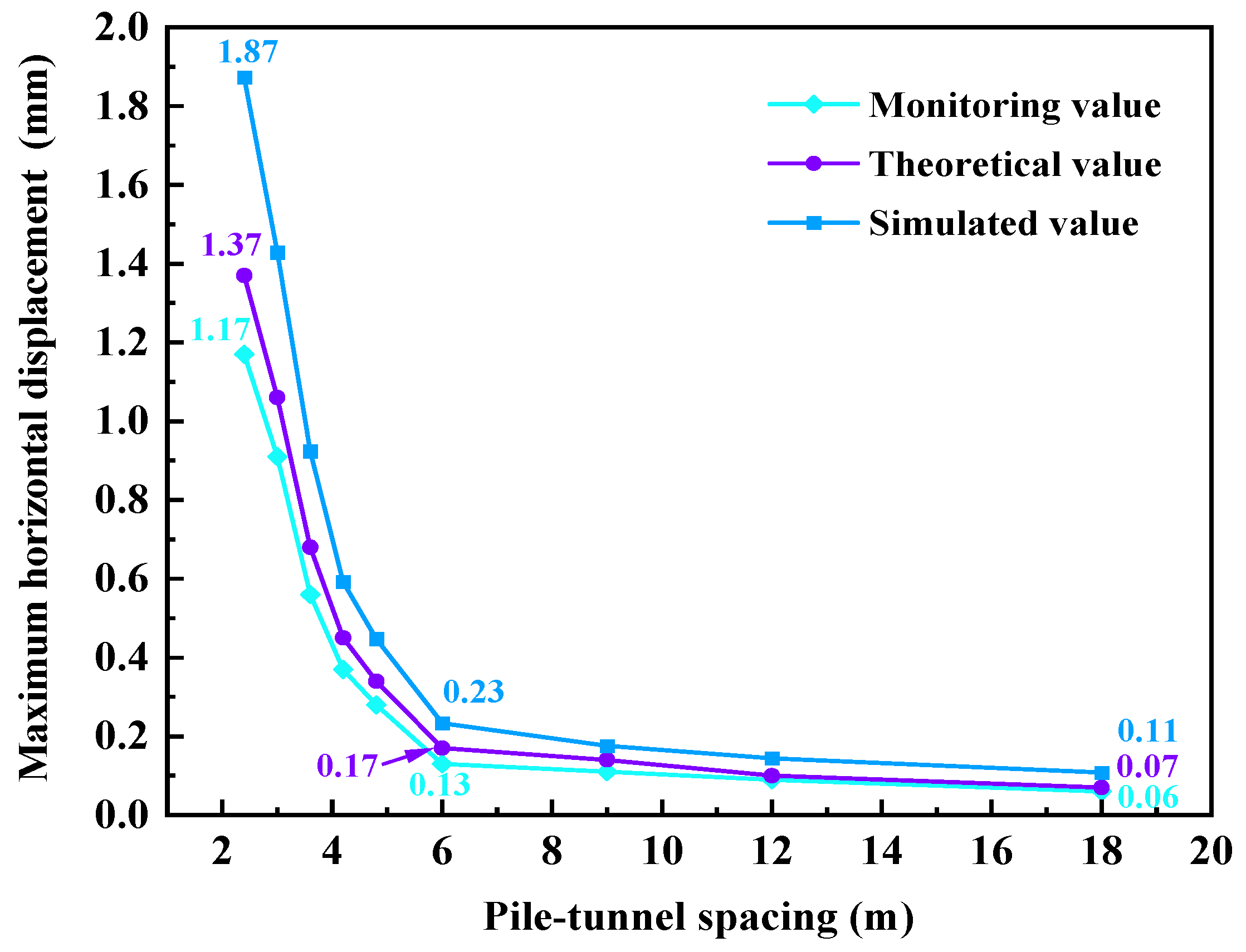
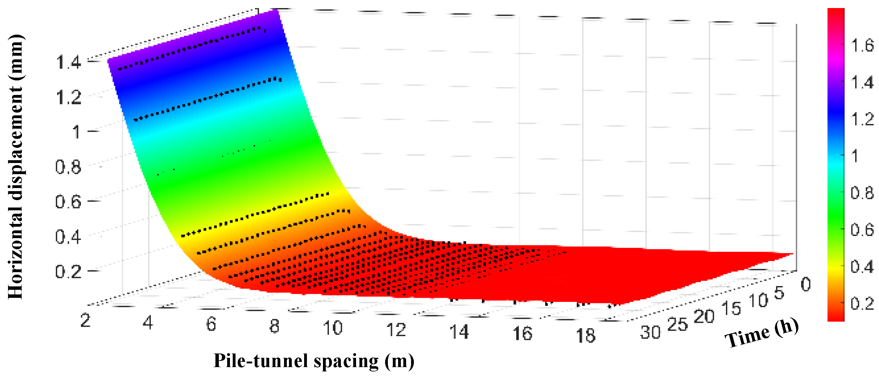
5.1. The Effect of Pile–Tunnel Spacing on Tunnel Deformation

The theoretical solutions, numerical solutions, and on-site measurement results for the impact of pile foundation excavation and unloading on the deformation of the lining of adjacent operating subway tunnels under different pile–tunnel spacings are presented in Figure 9 and Figure 10. These figures respectively illustrate the maximum vertical and horizontal deformations of the tunnel. The numerical simulations consider various pile–tunnel spacings. It can be seen in Figure 9 that the vertical settlement of the adjacent subway tunnel lining decreases gradually as the distance between the piles and the tunnels increases. As the distance between the piles and the tunnels increases from 2.4 m (0.4 D) to 6.0 m (1 D), the measured, theoretical, and simulated values of tunnel vertical displacement decrease from 0.86 mm, 1.04 mm, and 1.38 mm to 0.15 mm, 0.20 mm, and 0.27 mm, respectively. This represents a significant reduction of 82.5%, 80.8%, and 80.4% in each case. During the stage of increasing the distance between piles and tunnels from 6.0 m (1 D) to 18.0 m (3 D), the measured, theoretical, and simulated vertical displacements of the tunnel decreased to 0.07 mm (9.3%), 0.08 mm (11.5%), and 0.11 mm (11.6%), respectively, with a relatively gentle range of displacement changes. From Figure 10, it can be seen that within the range of one tunnel diameter (1 D), the horizontal displacement change of the tunnel lining caused by pile foundation excavation is greater than the vertical displacement. The measured, theoretical, and simulated values of the horizontal displacement of the tunnel show a substantial decrease of 88.9%, 87.6%, and 87.7%, respectively. Outside the range of one tunnel diameter, the horizontal displacement and vertical displacement of the tunnel lining are basically close, and the displacement change gradually slows down. This is because as the distance between the piles and the tunnel increases, the disturbance effect on the surrounding soil caused by pile foundation excavation gradually diminishes, thereby reducing the deformation impact on the tunnel lining. Based on the maximum displacement deformation law of tunnel lining, during pile foundation excavation construction in the hard plastic clay area of Hefei City, the distance between the pile and the tunnel is categorized using one and three times the tunnel diameter as division standards. Consequently, the area near the subway tunnel influenced by pile foundation excavation is classified into three zones: a high-impact zone, a moderate-impact zone, and a low-impact zone, as shown in Figure 11. When the pile foundation construction is located in a high-impact zone, the deformation of the lining caused by the pile foundation construction of adjacent tunnels is significant, and safety measures need to be taken to ensure the safe operation of the subway tunnel. When the distance between piles and tunnels is greater than one diameter of the tunnel, the deformation of the lining is relatively small. In practical engineering, priority should be given to pile foundation construction operations in moderate-impact zones and low-impact zones to minimize the deformation impact on the tunnel lining.

5.2. Impact of Time Variations on Tunnel Deformation

The maximum vertical and horizontal deformation of the lining of adjacent subway tunnels over time after excavation and unloading of pile foundations with the distance of 3 m (0.5 D) and 6 m (1 D) is shown in Figure 12 and Figure 13. It can be seen that the trend in the theoretical and simulated values is basically the same as the measured value curve of the on-site monitoring results. After the excavation of the pile foundation, both the vertical settlement and horizontal displacement of the tunnel lining increase continuously over time. The time required for the tunnel lining to reach a stable state varies depending on the distance between the piles and the tunnel, consequently leading to differing monitoring durations. Compared with the simulation results, the theoretical values obtained from analytical solutions exhibit greater proximity to the measured outcomes. When the distance between piles and tunnels is 6 m, after the tunnel lining displacement stabilizes, the cumulative measured vertical displacement is 0.16 mm, the theoretical value is 0.20 mm, and the simulated value is 0.27 mm. The cumulative measured value of horizontal displacement is 0.13 mm, the theoretical value is 0.17 mm, and the simulated value is 0.23 mm. Therefore, compared with numerical simulation methods, the analytical calculation method proposed can better reflect the disturbance effect of the surrounding cohesive soil caused by pile foundation excavation. It also demonstrates superior accuracy and applicability in evaluating the deformation of linings in adjacent operational subway tunnels.

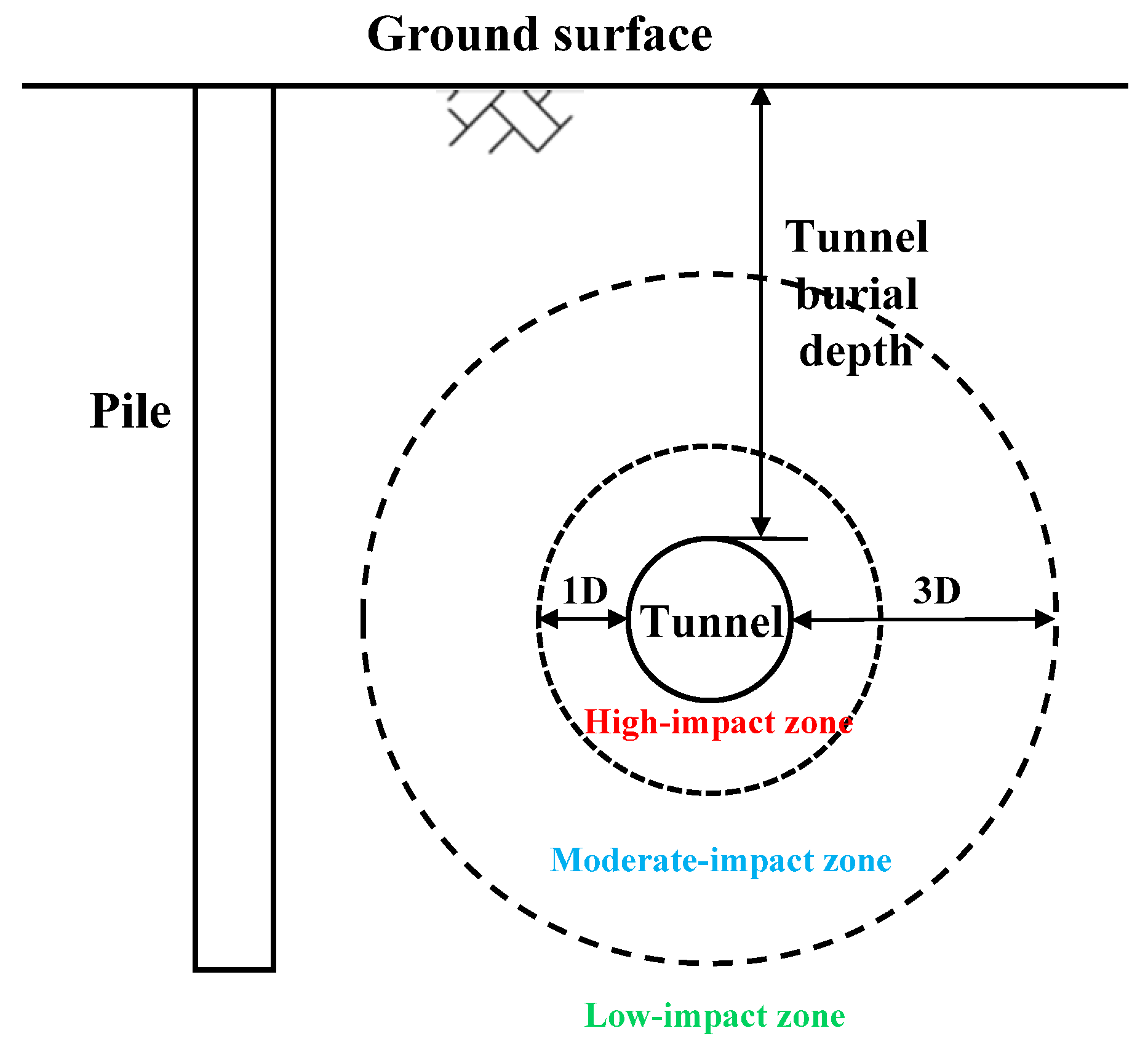
5.3. Tunnel Deformation Prediction Model

The theoretical solution formula proposed in this paper is relatively complex and has multiple parameters, which makes it inconvenient for practical engineering applications. To quantitatively investigate the time-dependent evolution of tunnel lining displacement under varying pile–tunnel distances, the nonlinear least squares (NLSs) method was applied to fit the theoretical calculation results, the pile–tunnel distance and measurement time were used as independent variables, and the vertical/horizontal displacements of the tunnel was used as dependent variables. Figure 14 and Figure 15 present the fitting surfaces, which further demonstrate that as the distance between pile foundation excavation and the adjacent subway tunnel increases, the lining displacement decreases, and the stabilization time shortens. The results based on theoretical solution data were compared and analyzed against on-site monitoring results. Figure 16 illustrates the vertical displacement fitting surface, exhibiting a correlation coefficient R2 = 0.975, which signifies a good degree of fitting. The surface equation is shown in Equation (15):
z v = 0.114 + 0.002 sin ( 0.482 π x y ) + 1.528 e 0.09 y 2
In the formula, the x, y, and zv parameters respectively represent time, pile tunnel spacing, and vertical displacement.
The horizontal displacement fitting surface is shown in Figure 16, exhibiting a correlation coefficient R2 = 0.984, which signifies a good degree of fitting. The surface equation is shown in Equation (16):
z h = 0.102 + 0.003 sin ( 0.318 π x y ) + 2.299 e 0.102 y 2
In the formula, the x, y, and zh parameters represent time, pile–tunnel spacing, and horizontal displacement, respectively.
Compare and analyze the measured pile tunnel spacing values (2.74 m, 3.02 m, 3.55 m, 4.0 m, 6.04 m) within the high-impact zone against the predicted values derived from the analytical solution fitting results. The vertical and horizontal displacements are illustrated in Figure 16 and Figure 17. From Figure 16, after the excavation of the pile foundation, the displacement of the adjacent tunnel lining increases rapidly with time. The smaller the distance between the pile and the tunnel, the greater the displacement, and the longer the stable deformation time of the lining. When the distance between the pile and tunnel is within 3 m, the vertical displacement is basically stable after 4–5 days. At 3–4 m, the vertical displacement reaches stability in about 3 days. At around 6 m, the vertical displacement stabilizes for about 2 days. The predicted value of vertical displacement is slightly greater than the measured value, with a maximum of no more than 0.2 mm, indicating good prediction performance. From Figure 17, after the excavation of the pile foundation, the horizontal displacement of the tunnel lining increases significantly more than the vertical displacement, with stabilization occurring within a maximum of 4 days. The predicted horizontal displacement closely matches the measured values, with a discrepancy not exceeding 0.15 mm, which indicates highly accurate prediction results. Based on the tunnel deformation prediction model and on-site measurement results, the monitoring duration for lining deformation in the affected area of the adjacent operating subway tunnel following pile foundation excavation can be accurately determined. This approach avoids unnecessary long-term monitoring and conserves labor and material resources. For construction in the high-impact zone (within 6 m), it is recommended to conduct monitoring for a period of 7 days. For construction in the moderate-impact zone (between 6 and 18 m), a monitoring duration of 3 days is advised. For construction in the low-impact zone (beyond 18 m), a 1-day monitoring period is sufficient.

6. Conclusions

This work incorporates the viscoelastic characteristics of the soil surrounding subway tunnels and proposes a theoretical calculation model for describing the deformation of the lining of adjacent operating subway tunnels induced by pile foundation excavation based on the Mindlin solution. The main conclusions are as follows:
(1) The theoretical values obtained from the analytical solution and the simulated values derived from the numerical model are in good agreement with the trends observed in the on-site monitoring results. The generalized Kelvin viscoelastic model can precisely characterize the creep process of cohesive soil during excavation unloading.
(2) The comparative analysis of the calculation results of subway tunnel deformation under different pile–tunnel spacing illustrates that the theoretical model calculation results are closer to the on-site measured values and can more effectively analyze the deformation impact of pile foundation excavation on adjacent operating subway tunnels.
(3) The simplified prediction equations for the vertical and horizontal displacements of a subway tunnel lining can be derived from theoretical solution data, with correlation coefficients of 0.975 and 0.984, respectively. A comparison of the predicted and measured values indicates that the simplified prediction model can accurately evaluate the deformation of the subway tunnel lining over time following pile foundation excavation and reasonably determine the duration of on-site monitoring.
(4) The impact zones of pile excavation in the hard plastic clay region near the subway tunnel in Hefei City are classified according to pile–tunnel spacing criteria of one and three times the tunnel diameter. In practical engineering applications, it is recommended to prioritize pile foundation construction outside the one-time tunnel diameter zone to minimize potential deformation impacts on the tunnel lining.
(5) This study primarily focuses on the hard plastic clay region of Hefei City, and its findings may not be fully representative of behaviors in other soil types or geological conditions. Future research will aim to extend the investigation to a broader range of geological settings to validate the applicability of the proposed model.

Author Contributions

Conceptualization, W.C.; investigation, D.W.; writing—original draft preparation, W.C.; writing—review and editing, D.W.; visualization, D.W. All authors have read and agreed to the published version of the manuscript.

Funding

This research was funded by the New Century Excellent Talents Support Program of the Ministry of Education (China), grant number NCET-12-0838.

Data Availability Statement

The original contributions presented in this study are included in the article. Further inquiries can be directed to the corresponding author.

Conflicts of Interest

The authors declare no conflicts of interest.

References

  1. Xu, L.; Xiang, P.; Qian, Y.; Yang, S.; Zhou, T.; Wang, F. Vulnerability Assessment of Urban Rail Transit Network—A Case Study of Chongqing. Buildings 2025, 15, 170. [Google Scholar] [CrossRef]
  2. Wei, Y.; Yang, X.; Xiao, X.; Ma, Z.; Zhu, T.; Dou, F.; Wu, J.; Chen, A.; Gao, Z. Understanding the Resilience of Urban Rail Transit: Concepts, Reviews, and Trends. Engineering 2024, 41, 7–18. [Google Scholar] [CrossRef]
  3. Wei, J.L.; Zhao, L.Y. Urban Road Network Vulnerability Assessment and Mitigation Strategies: A Case Study in Wuhan Main City. Mod. Urban Res. 2020, 35, 6. [Google Scholar]
  4. Zargarian, R. A new sustainability framework for urban underground space. Proc. Inst. Civ. Eng.-Eng. Sustain. 2016, 171, 238–253. [Google Scholar] [CrossRef]
  5. Li, X.; Liu, T.; Ju, S.; Guo, Y. Optimization and Impact Assessment of Excavation Sequence around Subway Stations from the Perspective of Sustainable Urban Development. Buildings 2024, 14, 1767. [Google Scholar] [CrossRef]
  6. Liu, B.; Yu, Z.; Yao, B.; Han, Y.; Liu, H.; Wang, S. Responses of the ground and adjacent pile to excavation of U-shaped tunnel. Comput. Geotech. 2021, 130, 103919. [Google Scholar] [CrossRef]
  7. Su, Y.; Zheng, G.; Diao, Y.; Li, Z.; Peng, J.; Jia, J.; Li, K.; Huang, J. Effect of excavation on adjacent tunnel and performance of grouting-based active protective method in spatially variable soil. KSCE J. Civ. Eng. 2025, 29, 100053. [Google Scholar] [CrossRef]
  8. Lueprasert, P.; Jongpradist, P.; Jongpradist, P.; Suwansawat, S. Numerical investigation of tunnel deformation due to adjacent loaded pile and pile-soil-tunnel interaction. Tunn. Undergr. Space. Technol. 2017, 70, 166–181. [Google Scholar] [CrossRef]
  9. Lin, G.; Ke, W.; Guo, S.; Lin, Z.; Xu, C.; Chi, M.; Xiao, Y. Influence of pile foundation construction on existing tunnels in a Metro Protection Area: Field Test and Numerical Simulation. Buildings 2024, 14, 2280. [Google Scholar] [CrossRef]
  10. Tao, W.; Le, W.; Nan, C.L. The Influence of Bridge Construction and Operation on Adjacent Nanjing Yangtze River Tunnels. Adv. Mater. Res. 2013, 838–841, 1018–1023. [Google Scholar]
  11. Schroeder, F.C. The Influence of Bored Piles on Existing Tunnels. Ph.D. Thesis, Imperial College London, London, UK, 2003. [Google Scholar]
  12. Yoo, C. Three-dimensional numerical investigation on the effect of bridge construction on existing tunnel. KSCE J. Civ. Eng. 2014, 18, 794–802. [Google Scholar] [CrossRef]
  13. Lueprasertl, P.; Jongpradist, P.; Charoenpak, K. Three-dimensional finite element analysis for preliminary establishment of tunnel influence zone subject to pile loading. Maejo. Int. J. Sci. Tech. 2015, 9, 209–223. [Google Scholar]
  14. Li, T.; Chen, G.; Liu, Y.; Luo, B.; Zhu, B. Mechanical Characteristics of the Combination System of Medium-Diameter Anti-Slide Piles and Tunnel-Under-Landslide Loading. Sustainability 2022, 14, 12135. [Google Scholar] [CrossRef]
  15. Yao, J.; Taylor, R.N.; McNamara, A.M. The effects of loaded bored piles on existing tunnels. In Geotechnical Aspects of Underground Construction in Soft Ground; CRC Press: Boca Raton, FL, USA, 2009; pp. 751–754. [Google Scholar]
  16. Sadek, M.; Shahrour, I. Use of the Boussinesq solution in geotechnical and road engineering: Influence of plasticity. Comptes Rendus. Mécanique 2007, 335, 516–520. [Google Scholar]
  17. Mindlin, R.D. Force at a point in the interior of a semi-infinite solid. Physics 1936, 7, 195–202. [Google Scholar] [CrossRef]
  18. Liang, R.Z.; Xia, T.D.; Huang, M.S.; Lin, C.G. Simplified analytical method for evaluating the effects of adjacent excavation on shield tunnel considering the shearing effect. Comput. Geotech. 2017, 81, 167–187. [Google Scholar]
  19. Liang, R.Z.; Wu, W.B.; Yu, F.; Liu, J.W.; Jiang, G. Simplified method for evaluating shield tunnel deformation due to adjacent excavation. Tunn. Undergr. Space Technol. 2018, 71, 94–105. [Google Scholar] [CrossRef]
  20. Jia, R.; Zheng, G.; Jiang, Y. The effect of clay structure formed during deposition on the ground deformation induced by shield tunneling. Tunn. Undergr. Space Technol. 2024, 147, 105689. [Google Scholar]
  21. Zeng, G.; Wang, H.; Jiang, M. Analytical solutions of noncircular tunnels in viscoelastic semi-infinite ground subjected to surcharge loadings. Appl. Math. Model. 2022, 102, 492–510. [Google Scholar] [CrossRef]
  22. Zhang, Z.; Chen, Y.; Han, Y.; Wei, G.; Pan, Y.; Sun, M. Mathematical modelling for interaction between soft ground and small curvature shield tunneling considering viscoelastic characteristics influences. Appl. Math. Model. 2024, 127, 607–639. [Google Scholar] [CrossRef]
  23. CJJT 202-2013; Technical Code for Protection Structures of Urban Rail Transit. China Architecture & Building Press: Beijing, China, 2013.
  24. GB 50911-2013; Code for Monitoring Measurement of Urban Rail Transit Engineering. Ministry of Housing and Urban-Rural Development of the People’s Republic of China: Beijing, China, 2013.
  25. Zhang, J.F.; Chen, J.J.; Wang, J.H.; Zhu, Y.F. Prediction of tunnel displacement induced by adjacent excavation in soft soil. Tunn. Undergr. Space Technol. 2013, 36, 24–33. [Google Scholar] [CrossRef]
  26. Zheng, W. Simplified method for evaluating mechanical interactions between tunnel and soil due to adjacent excavation. Tunn. Undergr. Space Technol. 2023, 139, 105205. [Google Scholar]
  27. Zhang, Z.; Zhang, M.; Zhao, Q. A simplified analysis for deformation behavior of buried pipelines considering disturbance effects of underground excavation in soft clays. Arab. J. Geosci. 2015, 8, 7771–7785. [Google Scholar] [CrossRef]
  28. Shi, X.; Rong, C.; Wang, H.; Cui, L.; Cai, H.; Wang, B. Analytical Study of Soil Displacement Induced by Twin Shield Tunneling in Semi-Infinite Viscoelastic Ground. Adv. Civ. Eng. 2020, 2020, 8839010. [Google Scholar]
Figure 1. Schematic diagram of urban viaduct adjacent to subway tunnel.
Buildings 15 01001 g001
Figure 2. Schematic diagram of pile–tunnel spacing.
Buildings 15 01001 g002
Figure 3. Monitoring in subway tunnels: (a) Monitoring point cross-sectional diagram. (b) Tunnel monitoring.
Buildings 15 01001 g003
Figure 4. The GDS triaxial rheological test system.
Buildings 15 01001 g004
Figure 5. Creep curve of confining pressure in graded unloading.
Buildings 15 01001 g005
Figure 6. The creep model fit curves against the test data.
Buildings 15 01001 g006
Figure 7. Generalized Kelvin model.
Buildings 15 01001 g007
Figure 8. Three-dimensional numerical model.
Buildings 15 01001 g008
Figure 9. Maximum vertical displacement of tunnels under different pile–tunnel spacing.
Buildings 15 01001 g009
Figure 10. Maximum horizontal displacement of tunnels under different pile–tunnel spacing.
Buildings 15 01001 g010
Figure 11. The impact zone of adjacent operating subway tunnels.
Buildings 15 01001 g011
Figure 12. The variation in the vertical displacement of the tunnel.
Buildings 15 01001 g012
Figure 13. The variation in the horizontal displacement of the tunnel.
Buildings 15 01001 g013
Figure 14. Vertical displacement surface fitting.
Buildings 15 01001 g014
Figure 15. Horizontal displacement surface fitting.
Buildings 15 01001 g015
Figure 16. Comparison between predicted and measured values of vertical displacement.
Buildings 15 01001 g016
Figure 17. Comparison between predicted and measured values of horizontal displacement.
Buildings 15 01001 g017
Table 1. Physical and mechanical properties of soil sample.
Density/(g·cm−3)Porosity RatioSaturation/%Internal Friction Angle φCohesion
c/kPa
2.010.67993.915.479.4
Table 2. Triaxial creep testing schemes.
Sample NameAxial Pressure (kPa)Confining Pressure (kPa)
1200100 → 75 → 50 → 25
2400200 → 150 → 100 → 50
3600300 → 225 →150 → 75
Table 3. The physical and mechanical parameters of materials.
Material Nameρ/(kg·m−3)E/MPavInternal Friction Angle φCohesion
c/kPa
Plain fill186010.80.3511.835.8
Clay201030.50.315.479.4
Sandstone223028,0000.1835240
Tunnel250035,0000.2--
Pile 250030,0000.3--
Table 4. Creep model parameters.
Model ParameterK/MPaGk/MPaηk/MPa·hG1/MPa
Clay24.7512.70334.79.67
Disclaimer/Publisher’s Note: The statements, opinions and data contained in all publications are solely those of the individual author(s) and contributor(s) and not of MDPI and/or the editor(s). MDPI and/or the editor(s) disclaim responsibility for any injury to people or property resulting from any ideas, methods, instructions or products referred to in the content.

