Article

Investigation of Power-Law Fluid Infiltration Grout Characteristics on the Basis of Fractal Theory

by
Fucheng Wei
,
Jinxing Lai
* and
Xulin Su
School of Highway, Chang’an University, Xi’an 710064, China
*
Author to whom correspondence should be addressed.
Buildings 2025, 15(6), 987; https://doi.org/10.3390/buildings15060987
Submission received: 18 February 2025 / Revised: 11 March 2025 / Accepted: 14 March 2025 / Published: 20 March 2025
(This article belongs to the Section Building Structures)

Abstract

:
This study advances the theory of power-law fluid infiltration grouting by developing spherical and columnar diffusion models rooted in fractal porous media theory and power-law rheological equations. An analytical solution for determining the slurry diffusion radius is derived and validated through laboratory experiments and numerical simulations. Key findings include the following: (1) The fractal permeability constant demonstrates an exponential dependence on the rheological index (n), with a critical threshold at n = 0.4. Below this threshold, the constant asymptotically approaches zero (slope < 0.1), while beyond it, sensitivity intensifies exponentially, attaining 0.48 at n = 0.9. (2) Non-linear positive correlations exist between the slurry diffusion radius and both the grouting pressure (P) and the water–cement ratio (W/C). Spherical diffusion dominates over columnar diffusion, with their ratio shifting from 1:0.96 at P = 0.1 MPa to 1:0.82 at P = 0.5 MPa. The diffusion distance differential increases from 22 mm to 38 mm as the W/C rises from 0.5 to 0.7, attributable to reduced interfacial shear resistance from decreasing slurry viscosity and yield stress. (3) Experimental validation confirms exponentially decaying model errors: spherical grouting errors decrease from 21.54% (t = 5 s) to 8.43% (t = 15 s) and columnar errors from 25.45% to 10.17%, both within the 50% engineering tolerance. (4) Numerical simulations show that the meander fractal dimension (48 mm) demonstrates a higher sensitivity than the volume fractal dimension (37 mm), with both dimensions reaching maximum values. These findings establish a theoretical framework for optimizing grouting design in heterogeneous porous media.

1. Introduction

Engineering practice shows that grouting technology, a crucial means for enhancing geotechnical physical properties [1], has been extensively employed in mining, water conservancy, and traffic tunneling engineering due to its minimal construction disturbance and high process adaptability [2,3,4,5,6]. Power-law fluids exhibit non-linear rheological properties, with the pure cement (water–cement ratio: 0.5–0.7) and mud grout (clay content: > 30%) used in projects being typical examples [7,8,9,10]. These power-law fluids demonstrate unique advantages in grouting projects under various heterogeneous geological conditions.
Since Mandelbrot [11] established the fractal theory system, it has provided a new paradigm for quantitatively characterizing the non-homogeneity of porous media. In recent years, the application of fractal theory in the field of grouting has made significant progress. In engineering, Huang et al. [12] investigated the mechanical properties and damage characteristics of yellow sandstone and its grouted rock and studied their fractal dimensions. Zhou et al. [13] constructed a diffusion model for single-hole grouting and multi-hole grouting methods based on fractal geometry and filtration effects. Hongyuan et al. [14] conducted a series of diffusion experiments on non-aqueous reactive swelling polymers in gravel media under dynamic water conditions using a custom experimental setup. Their study revealed the effects of grouting parameters, such as the dynamic pump pressure, the mass fractal dimension, and the grouting volume, on the effective diffusion length and water plugging rate of the slurry. Zhou et al. [15] performed filtration, permeability, and uniaxial compressive strength studies to better understand the effects of grouting temperature, the water–cement ratio, and mass fractal dimensions on slurry-particle retention, the permeability of the injected medium, and cementation strength under constant-pressure conditions. Sun et al. [16] developed an enhanced grouting prediction model that incorporates interrelated defects in pore fractal properties, time-dependent slurry rheological characteristics, and infiltration. Du et al. [17] introduced a novel infiltration model, utilizing fractal theory to describe the intricacy of flow paths in soil, enabling the quantification of maximum grout infiltration distances across soils with varying dry densities. Yao et al. [18] examined the formation of fractures surrounding coal-seam boreholes and analyzed how fractal-tree fracture-network structural parameters influence the penetration of slurry materials.
In theoretical research, Yang et al. [19] proposed a fine seepage equation of motion for Newton fluids, incorporating the effect of curvature on the grouting process of gravel soil, and analyzed the column-hemisphere infiltration grouting mechanism through theoretical analysis. Zhang et al. [20], Wang et al. [21], and others derived a two-stage column-hemispherical diffusion model for Newtonian fluids based on fractal theory, considering the tortuosity of the porous medium and the viscous behavior of the slurry over time. The effects of the injection flow rate, slurry viscosity, and pore tortuosity on the injection pressure and diffusion radius in the constant-flow injection mode were analyzed. For non-Newtonian fluids, Yang et al. [22] developed a fractal roughness model for the transport of a fractional non-Newtonian fluid. Xu et al. [23] proposed the infiltration grouting mechanism of a Bingham fluid, considering the pore size distribution of porous media based on fractal theory and the rheological equation of the Bingham fluid. Wang et al. [24,25] established a viscous time-varying Bingham fluid based on the fractal theory of porous media and the viscous time-varying Bingham fluid seepage equation of motion using an infiltration grouting theoretical model with a spherical infiltration grouting model fluid, considering the slurry diffusion path and the time-variable viscosity. Zhou et al. [26] combined the fractal theory to establish a column infiltration grouting model of a Bingham fluid. Regarding power-law fluids, Wang et al. [27,28] established fractal models for spherical and radial seepage of power-law fluid diffusion; Zhang et al. [29] investigated power-law fluids in porous media in plane-parallel flow and established a fractal model for permeability; and Li et al. [30] derived fractal flow rates, average velocities, and effective permeabilities for power-law fluid flow in fractal soils composed of capillaries with circular cross-sections. Xiao et al. [31] derived a fractal model to characterize the permeability of a power-law fluid through a fractured porous medium with fractal concave and convex surfaces. Yun [32] presented a fractal model of the flow rate, velocity, effective viscosity, apparent viscosity, and effective permeability of power-law fluids based on the fractal properties of porous media. Yang et al. [33] developed a power-law flow-column diffusion model considering dimensionality and investigated the influence of bending effects on slurry diffusion. Wu et al. [34] developed a fractal model of the effective permeability of a power-law fluid in a dual fracture-pore medium based on fractal theory and technique and the generalized form of Darcy’s law, considering the effect of scuttling between a pore capillary and a crack.
However, existing studies on power-law fluid grouting research have limitations: (1) the theoretical models lack experimental validation and (2) numerical simulations of the diffusion process are often restricted to analyzing the influence of a single fractal dimension. This paper establishes a power-law fluid seepage control equation with fractal dimensions ( D f and D T ) to derive analytical solutions for spherical and columnar diffusion. Multi-scale validation was conducted by (1) investigating the influence of the rheological index on fractal permeability, (2) analyzing the effects of grouting pressure and the water–cement ratio on the spherical and columnar diffusion of power-law fluids, (3) performing indoor grouting experiments and measuring fractal parameters to verify the theoretical model’s validity, and (4) conducting numerical simulations to examine the power-law fluid grouting diffusion process and the effects of different fractal dimensions on grouting diffusion. The study’s primary contribution is the first quantification of the differential effects of meander fractal dimensions and volume fractal dimensions on diffusion and the theory’s practical verification through experiments.

2. Modeling of Power-Law Fluid Diffusion Fractal Infiltration Grouting

2.1. Fractal Modeling of Porous Media

The structures of porous media are highly complex and variable, making it challenging to accurately describe the shape, size, and distribution of pores. In grouting studies, researchers often simplify porous media, typically representing pores as straight channels, as illustrated in Figure 1a. However, this simplification diverges from the actual curved distribution of pores in soil, depicted in Figure 1b. While this simplified model facilitates easier calculations, it introduces significant theoretical and experimental errors. Fractal theory offers a more precise method for describing fragmented, highly irregular, and complex geometric objects with fine structures. By applying fractal theory, researchers can more accurately characterize the irregular pores on the surface of porous media and the pore channels within soil layer layers [35,36].
The pore size distribution on the surface of a porous medium can be characterized by an equivalent diameter, λ, and the total cumulative number of pore areas, N can be represented using a power function [37]:
N ( I > λ ) = λ max λ D f
Simultaneous differentiation of both sides of Equation (1) and solving for it gives the following:
d N = D f λ max D f λ D f 1 d λ
where λmax represents the maximum value of the pore size, λmax denotes the number of fractal dimensions (1 < Df < 2 in two dimensions and 1 < Df < 3 in three dimensions), and −dN > 0 indicates that the cumulative total decreases as λ increases.
For the degree of curvature of the pore aperture, the degree of tortuosity, τ′, is defined. At this point the effective length of the pore channel, Le, and the tortuosity, τ′, can be expressed as follows [38,39]:
L e = L D T λ 1 D T
τ = L e L = L λ m i n D T 1
where D T represents the tortuous fractal dimension ( 1 D T 2 ) and L signifies the length of the channel. D T = 1 represents that the pore channel is straight, and D T = 2 represents that the pore channel is curved to the extent that it occupies the entire plane.
The establishment of the fractal parameters D f and D T enables the description of pores as well as pore channels in porous media.

2.2. Fractal Dimension Power-Law Fluid Percolation Equation

In grouting engineering, a typical power-law fluid slurry is a pseudoplastic cement liquid slurry fluid when the slurry water–cement ratio (W/C) is in the range of 0.5 to 0.7 [1,40,41]. The rheological equation of governing power-law fluids is expressed as follows:
τ = C γ n
μ a = C γ n 1
where τ represents the shear stress, C represents the coefficient of consistency, n represents the power index, μ a represents the apparent viscosity, and γ = d v d r represents the shear rate.
The motion of slurry within a single pipe can be described by the following equation [42]:
q = π n 1 + 3 n λ 2 1 + 3 n n 1 2 C d P d L 1 n
To account for the bending effect of the pore, the concept of effective length, L e , is introduced. Consequently, the effective length is used instead of the length of the pore, which can be reformulated as follows:
q = n π 1 + 3 n λ 2 1 + 3 n n 1 2 C d P d L e 1 n
Considering the correlation between the effective length and the number of meandering subdimensions, Equation (3) is correlated with the aforementioned equation:
q = π n 1 + 3 n λ 2 1 + 3 n n λ D T 1 D T L D T 1 1 n 1 2 C d P d L 1 n
The equation above represents the single-channel power-law fluid flow under fractal theory. When the fluid flows along the x or the r direction, Formula (3) can be modified to r e = r D T λ 1 D T or x e = x D T λ 1 D T , respectively. By incorporating these modifications into Formula (9), we can derive the flow equation for a single-channel power-law fluid flowing along the x or r direction.
In the context of porous media, the seepage equation for a single channel is extended to encompass the porous space. The flow rate of the power-law fluid in this scenario is represented as follows:
V = 1 A 0 λ min λ max q d N
where A 0 represents the area of the chosen reference plane in cm 3 . Equations (2) and (9) are substituted into Equation (10) and subsequently integrated to yield the following:
V = π n 2 D f λ max D T n + 3 8 A 0 1 4 D T 1 n 1 λ min λ max D T n D f + 3 1 + 3 n D T D f n + 3 n × 1 L D T 1 n 1 C d p d L 1 n
Disregarding the fractal case, the slurry fluid consistency coefficient, independently of the pressure factor, is defined as the power-law fluid effective permeability. This coefficient depends solely on the intrinsic properties of the slurry itself. If we denote α = D T 1 , then the effective permeability of the slurry can be written as follows:
K = π n 2 D f λ max D T n + 3 8 A 0 1 4 D T 1 n 1 λ min λ max D T n D f + 3 1 + 3 n D T D f n + 3 n 1 n n 1 L D T 1 n = K c n 1 L α n
K c = π n 2 D f λ max D T n + 3 8 A 0 1 4 D T 1 n 1 λ min λ max D T n D f + 3 1 + 3 n D T D f n + 3 n 1 n
The permeability constant for a power-law fluid in a fractal geometry is expressed in terms of the parameter K c , which represents the permeability under straight-pipe conditions ( D T = 1 or α = 0 ).
The flow rate of the slurry through the pore in a power-law fluid can be expressed as follows:
v = K C 1 n d p d L 1 n = K c C 1 n 1 L D T 1 α d p d L 1 n

2.3. Power-Law Fluid Spherical Diffusion Fractal Infiltration Grouting Model

Considering the assumption of spherical diffusion for Newtonian fluid slurry (as shown in Figure 2), the diffusion path, i, can be simplified to a spherical directional flow ( L in Equation (14) is substituted with r ). The slurry injection volume can be expressed by the following equation:
Q s = V p = ϕ V b
where V p represents the effective volume of grouting (total capillary volume), V b represents the total volume of the sphere model, and ϕ represents the porosity.
For an individual capillary with a diameter denoted as λ , the individual capillary volume is π λ 2 d r e / 4 . The spherical model area is given by A 0 , and the total volume is subsequently calculated as follows:
V p = λ min λ max π λ 2 4 d r e λ min λ max 4 π r 2 A 0 d N c
The total volume of the column model is V b = 4 π r 2 d r , resulting in a porosity as follows:
ϕ = V p V b = 1 2 π r h d r λ min λ ma x π λ 2 4 d r e λ min λ max 2 π r h A 0 d N c = 1 d r λ min λ max π λ 2 4 A 0 d r e d N c
Substitute Equations (2) and (3) into the aforementioned equation and perform the following integration:
ϕ = π D f D T λ max 3 D T 4 A 0 1 λ min λ max 3 D T D f D T + D f 3 r D T 1
A factor independent of the injected material’s nature determines the fractal porous medium’s porosity, which is solely dependent on the medium’s structure, ϕ c . Utilizing the fractal porosity constant, let α = D T 1 , as previously stated:
ϕ = ϕ c r α
ϕ c = π D T D f λ max 3 D T 4 A 0 λ min λ max 3 D T D f D T + D f 3
During the flow diffusion of the slurry, the total grouting flow rate adheres to the following equation [31]:
Q s = ν A b t
where A b represents the ball model grouting area, A b = 4 π r 2 .
Substitute Equation (14) into Equation (21):
ν = Q s 4 π r 2 t = K C 1 n d p d L 1 n
Separate the variables for Equation (22).
d p = C K Q s 4 π t n 1 r 2 n dr
Considering the boundary conditions, for the initiation of grout diffusion, when r = r 0 and p = p 1 , r 0 denotes the radius of the grouting pipe and p 0 represents the head pressure at the grouting point. After time t , when r = r 1 and p = p 0 , r 1 represents the radius of the slurry diffusion and p 1 denotes the grouting pressure. Substituting these into Formula (23), the integral can be obtained:
Δ p = p 1 p 0 = C K Q s 4 π t n r 1 1 2 n r 0 1 2 n 1 2 n
Taking into account Equation (21) ( Q s = ϕ V b = ϕ c r 1 α 4 π r 1 3 / 3 ) and substituting Equation (13) into Equation (24), the power-law fluid spherical shape diffusion fractal infiltration grouting diffusion equation can be expressed as follows:
Δ p = p 1 p 0 = C ϕ c r 1 3 + α + α n 2 3 K c t n r 1 1 2 n r 0 1 2 n 1 2 n

2.4. Power-Law Fluid Column Diffusion Fractal Infiltration Grouting Model

Assuming that the power-law body slurry diffusion in the formation follows a columnar grouting model, the slurry diffuses through apertures in the formation. When observed along the columnar cross-section, this diffusion can be simplified to a planar radial flow. Figure 3 illustrates the columnar infiltration grouting model. During the flow diffusion of the slurry, the total grouting flow rate adheres to the following equation [31]:
Q c = ν A p t
where A p represents the area of the column model grouting and A p = 2 π r h . By substituting Equation (14) into the aforementioned equation, the following can be obtained:
ν = Q c 2 π r h t = K C 1 n d p d r 1 n
Applying the method of the separation of variables to Equation (29) yields the following:
d p = C K Q c 2 π h t n 1 r n d r
The boundary conditions remain consistent with those for spherical grouting. These conditions are derived by substituting the boundary parameters into Equation (28) and performing integration:
Δ p = p 1 p 0 = C K Q c 2 π h t n r 1 1 n r 0 1 n 1 n ( n 1 )
Taking into account Equation (26) ( Q c = ϕ V b = ϕ c r 1 α π r 1 2 h ) and substituting Equation (13) into Equation (31), the power-law fluid columnar shape diffusion fractal infiltration grouting diffusion equation can be expressed as follows:
Δ p = p 1 p 0 = C ϕ c r 1 2 + α + α n 2 2 K c t n r 1 1 n r 0 1 n 1 n ( n 1 )

2.5. Scope of Application of the Formula and Discussion

2.5.1. Scope of Use of the Formula

The diffusion equation presented in this paper is predicated on the movement of slurry within the formation. Consequently, the solution to the fractal penetration grouting diffusion equation must adhere to the following assumptions:
(1)
The fluid movement within the formation is characterized by laminar flow, with a Reynolds number Re < 2000 ;
(2)
The impact of the slurry’s self-weight is disregarded during the grouting process;
(3)
The injected porous medium consists of isotropic material, and the grouting process employs constant-pressure grouting;
(4)
In the context of a porous medium, the fractal dimension must adhere to specific constraints: D T 1 < D T < 2 and D f 2 < D f < 3 .

2.5.2. Solving for the Fractal Dimension

Determining the fractal dimensions D f and D T is essential for deriving the diffusion equation. This equation can be resolved through normalization using the probability density function [43,44]:
D f = d ln ϕ ln λ min λ max
D T = 1 + ln τ av ln L λ av
where d represents the number of spatial geometric dimensions, with d = 2 for a two-dimensional planar space and d = 3 for a three-dimensional space; ϕ represents the porosity; τ a v represents the average tortuosity; and λ a v represents the average capillary diameter, which can be calculated using the following equation [44,45,46]:
λ av = D f D f 1 λ min 1 λ min λ max D f 1
τ av = 1 2 1 + 1 2 1 ϕ + 1 ϕ 1 1 ϕ 1 2 + 1 4 1 1 ϕ

2.5.3. Discussion of the Diffusion Equation

Equation (25) represents the power-law fluid spherical diffusion equation, and Equation (30) represents the power-law fluid column diffusion equation. In these equations, K c , ϕ c , and α are associated with fractal parameters, the D T and D f coefficients. When the soil material is determined, D T and D f assume certain values. Grouting parameters, including the slurry property parameters C and n , can be determined through experimentation. Additionally, the grouting parameters Δ p , t , and r 1 are interrelated; knowing any two of these parameters allows for the determination of the third.
When the power index n = 1 and C = μ a , the power-law fluid is spherical, and columnar grouting diffusion equations can be transformed into Newtonian fluid grouting spherical and columnar diffusion equations (the columnar diffusion equation is derived from a reintegration of Formula (28)). These transformations are represented in Formulas (35) and (36):
Δ p = p 1 p 0 = μ a ϕ c r 1 3 + 2 α 3 K c t ( 1 r 0 1 r 1 )
Δ p = p 1 p 0 = μ a ϕ c r 1 2 + 2 α 2 K c t ln r 1 r 0
Upon considering α = 0 , this can be transformed into a grouting formula for the straight-pipe limit condition. If pore fractals are disregarded, the formula can be simplified to a conventional grouting equation:
Δ p = p 1 p 0 = μ a ϕ r 1 3 3 K c t ( 1 r 0 1 r 1 )
Δ p = p 1 p 0 = μ a ϕ r 1 2 2 K c t ln r 1 r 0

3. Study of the Laws of Diffusion

In order to study the diffusion law of each parameter on the power-law type slurry, this study focused on the rheological index, the grouting pressure, and the water–cement ratio. The liquid rheological parameters were based on the findings of Kong et al. [47], with the rheological equations presented in Table 1. Generally, the span of the diameter covers three orders of magnitude [48]. If expressed as λ min / λ max = 10 n , then n > 2 . Additional parameters are detailed in the accompanying figure labels.
Analysis of Figure 4 reveals an exponential relationship between the fractal permeability constant and the rheological index (The figure shows the fractal permeability constant obtained for every 0.5 increase in the rheological index from 0 to 9). When the rheological index is below 0.4 (slope < 0.1), the sensitivity of the power index to the fractal permeability constant is low. However, the relationship becomes exponential when the rheological index exceeds 0.4, with the fractal permeability constant reaching 0.48 at a rheological index of 0.9. The fractal permeability constant exhibits a positive correlation with fractal permeability, indicating that fractal permeability increases as the rheological index rises. This finding aligns with the conclusions drawn by Zhang et al. [29] in their fractal analysis study of power-law fluid permeability in porous media.
The analytical results from Figure 5 demonstrate a non-linear positive correlation between the grouting pressure and the diffusion radius. At a 0.1 MPa pressure level, both spherical and columnar diffusion models exhibit comparable diffusion characteristics. However, as the grouting pressure increases, the spherical diffusion model demonstrates a greater diffusion distance and growth rate compared to the column diffusion model. Quantitative analysis reveals that at 0.1 MPa, the columnar-to-spherical diffusion ratio reaches 1:0.96, suggesting minimal geometric constraint effects under low-pressure grouting conditions. This ratio shifts to 1:0.82 when the pressure increases to 0.5 MPa. This phenomenon can be attributed to the isotropic advantage of slurry flow in the spherical diffusion model, which exhibits a lower energy dissipation rate compared to the directional flow in the column diffusion model.
The analytical study presented in Figure 6 demonstrates a non-linear positive correlation between the diffusion radius and the water–cement ratio. As the water–cement ratio increases, the diffusion distance of the spherical model exceeds that of the column model. Specifically, when the water–cement ratios are 0.5, 0.6, and 0.7, the ratios of columnar to spherical diffusion distances are 0.92, 0.87, and 0.83, respectively. This indicates that the penetration efficiency advantage of spherical grouting becomes more pronounced at higher water–cement ratios. Mechanistically, increasing the water–cement ratio leads to a synergistic decrease in both slurry viscosity and yield stress, which reduces the shear resistance at the slurry–soil interface and promotes seepage diffusion. This conclusion aligns closely with the practical engineering application of high-water–cement ratio slurries for long-distance fissure sealing.

4. Indoor Grouting Experiment

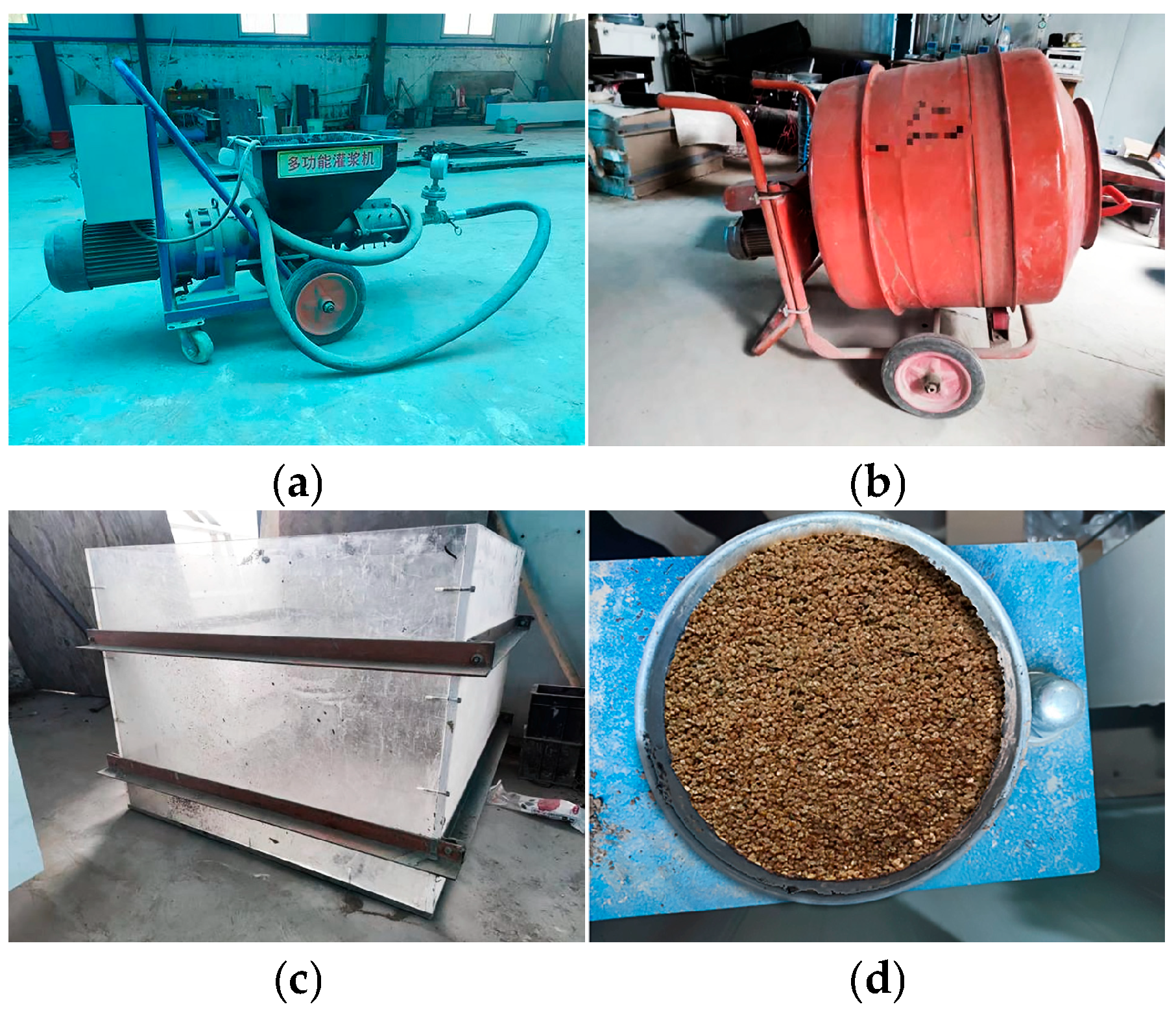
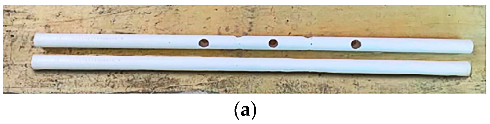
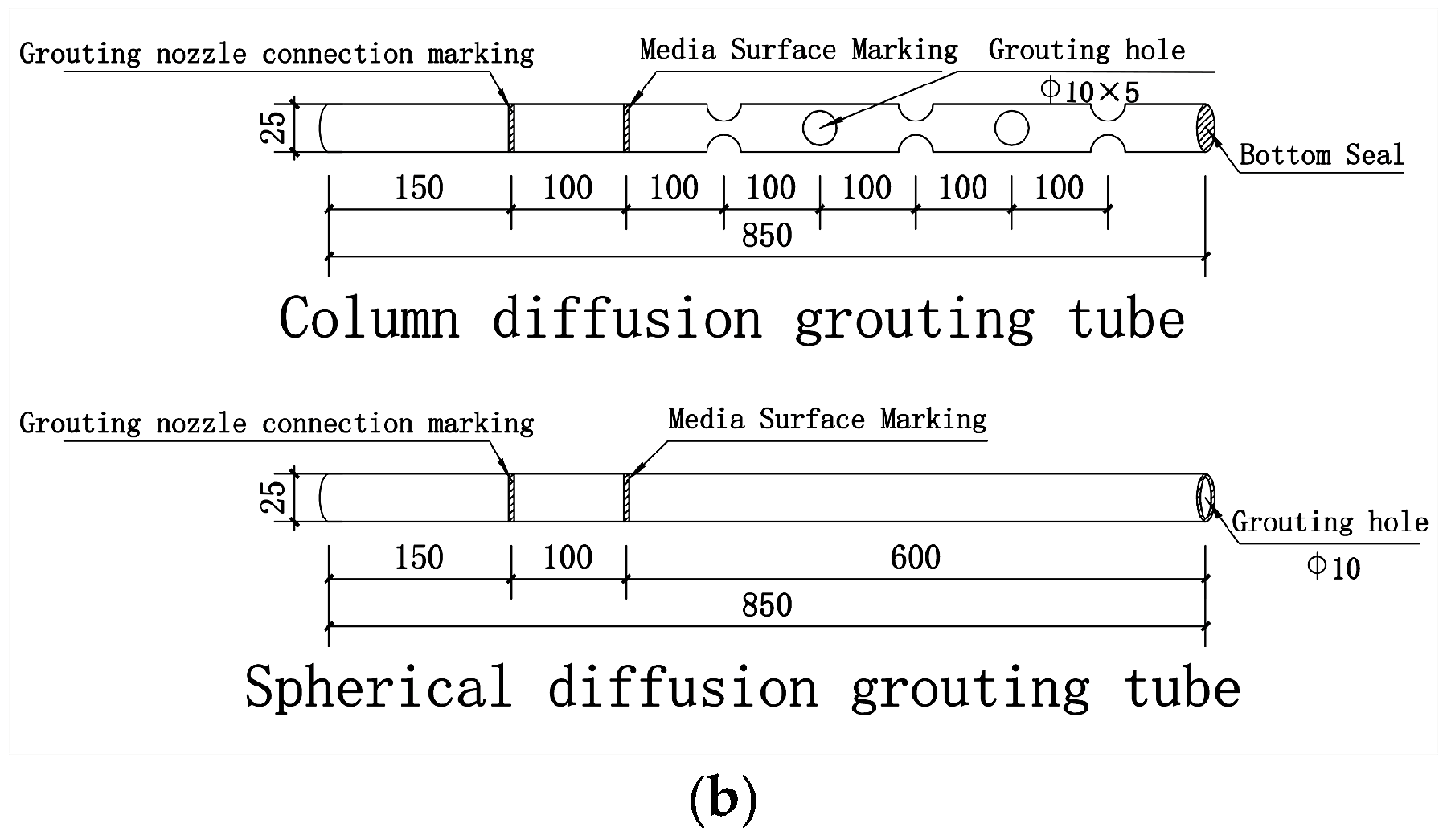
4.1. Experimental Setup and Grouting Materials

The experimental setup contained three parts, a grouting machine (#FT-32, Renxian Feitai Machinery Factory, Xingtai, China), a mixer, and a model box. Images of the experimental objects are shown in Figure 7.
The materials for this experiment included grouting material and an injected medium. The grouting material was an ordinary silicate cement (cement code P O   42 . 5 ) produced by the Gansu Qilianshan Cement Factory, and the rheological equations can be referred to in the literature [5]. The injected medium was coarse sand, and the characteristics of the injected material are presented in Table 2.
The grouting pipe had a diameter of 25 mm, and the pipe material was PVC material. A physical image of the grouting tube is shown in Figure 8a, and a detailed drawing is shown in Figure 8b.

4.2. Determination of Fractal Parameters and Design of Grouting

The experiment utilized coarse sand as the injected porous medium, as illustrated in Figure 7d. This section primarily aimed to determine the fractal parameters, focusing on the average tortuosity, τ av ; the porosity of the porous medium, ϕ ; the maximum pore diameter, λ max ; and the minimum pore diameter, λ min .
Among the aforementioned parameters, determining the values for λ max and λ min presented the greatest challenge. This study employed Adobe Photoshop (cs6.0) software to analyze high-resolution images for parameter determination. The specific procedure is as follows:
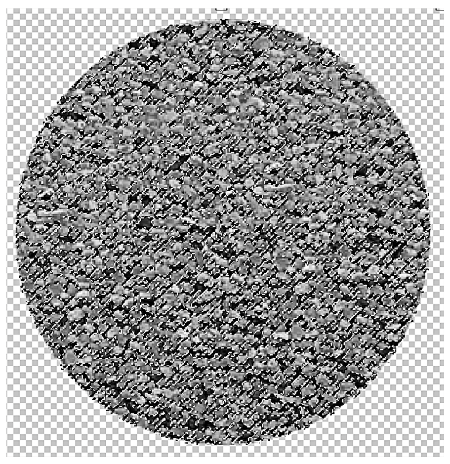
  • A high-resolution image of the injected medium is imported into the software and subsequently converted to a black-and-white format.
  • The software’s color range feature is utilized to select the sample pores (Figure 9).
  • The analysis tool is utilized to record measurements and identify the pixel area with the largest area in all the black ranges. The conversion results in λ max . The minimum pore diameter differs from the maximum pore diameter by three orders of magnitude [48]. λ max can be calculated using λ min .
The value of ϕ can be measured in the laboratory, and using the parameters λ max , λ min , and ϕ , combined with Formula (31), the volume fractal dimension number D f was obtained. The calculated results are shown in Table 2.
Based on Formulas (32)–(34), the tortuous fractal dimension, D f , and the maximum grouting diffusion radius, L, are interconnected. To determine the value of D f , it is necessary to perform a back-calculation using the L value. The resulting calculations are presented in Table 3, below.

4.3. Experiments and Analysis of Results

The water–cement mass ratio of the slurry used in the test was 0.7:1. The measured viscosity coefficient was 1.482 Pa·s, the rheological index value was 0.287, and the viscosity of the water was 0.001 Pa·s. The experimental setup comprised two groups of experiments, each utilizing three model boxes. The first group included power-law fluid sphere grouting experiments designated as K1, K2, and K3, and the second group of performed power-law fluid column experiments were labeled S1, S2, and S3. During the experiment, maintaining a constant grouting pressure proved challenging; therefore, the grouting pressure approached 0.4 MPa. The experiments were timed at 5 s, 10 s, and 15 s, marked as 1, 2, and 3.
Following a 7-day period of test-chamber maintenance, the mold was disassembled and the maximum diffusion radius was measured using a straightedge. The experimental results were shown in Figure 10.
The experimental values, theoretically calculated values, and difference analyses presented in Table 3 are visually represented in Figure 11 and Figure 12.
The analysis of the results presented in Table 2 and Figure 11 and Figure 12 revealed time-dependent decay characteristics in the relative errors between the theoretical predictions and the experimental values for the power-law fluid spherical and column grouting in the fractal porous media. For the spherical grouting, the theoretical–experimental error converged asymptotically from an initial 21.54% (t = 5 s) to 8.43% (t = 15 s). Similarly, for the column grouting, the error converged non-linearly from 25.45% (t = 5 s) to 10.17% (t = 15 s). Notably, the theoretical values consistently exceeded the experimental values. Despite this deviation, all data points remained within the accepted engineering tolerance range (−50% to 100%) [40], aligning with widely applied engineering and experimental practices.
To analyze the reasons for the error, the following main points were considered:
  • Neglect of the effect of the pressure-loading dynamic process
The theoretical model simplified the grouting pressure to a steady-state boundary condition (P = 0.4 MPa), without considering the transient pressure increase from 0 Mpa to 0.4 Mpa. This pressure gradient establishment period resulted in the actual slurry front migration distance exceeding the theoretical migration value. The model can be refined by introducing a time-varying pressure function to account for this discrepancy.
2.
Geometric constraint and gravity coupling effect
The columnar grouting holes were positioned at intervals of 100 mm, and the overlapping pressure fields of the adjacent grouting holes induced an interference effect. This interference caused the predicted values of columnar diffusion to deviate from the measured results. Additionally, the variability in the gravity vector direction necessitated that the column grouting process overcome the formation’s normal stress. Conversely, the spherical grouting process benefited from the gravity potential energy, which enhanced the radial permeability efficiency.
3.
Multi-scale uncertainty sources
The temporal variation in slurry properties (specifically, the rheological evolution of the slurry’s shear dilution index as it decayed over time) was not considered, the heterogeneity of the medium (the anisotropy of the injected material) was not incorporated into the fractal parameter calculations, and measurement system errors (including those from pressure sensors, stopwatches, and other instrumentation) were not accounted for in this analysis.

5. Numerical Modeling Study

To investigate the influence of fractal theory parameters on the experimental results for the power-law fluid grouting within the framework of this paper’s model, numerical simulations were conducted using COMSOL Multiphysics 6.0 software. The porous media and groundwater flow module of the software was utilized, and the grouting process was simulated using Darcy’s constitutive models. The simulations employed the same porous media and slurry parameters as those described in Section 4.

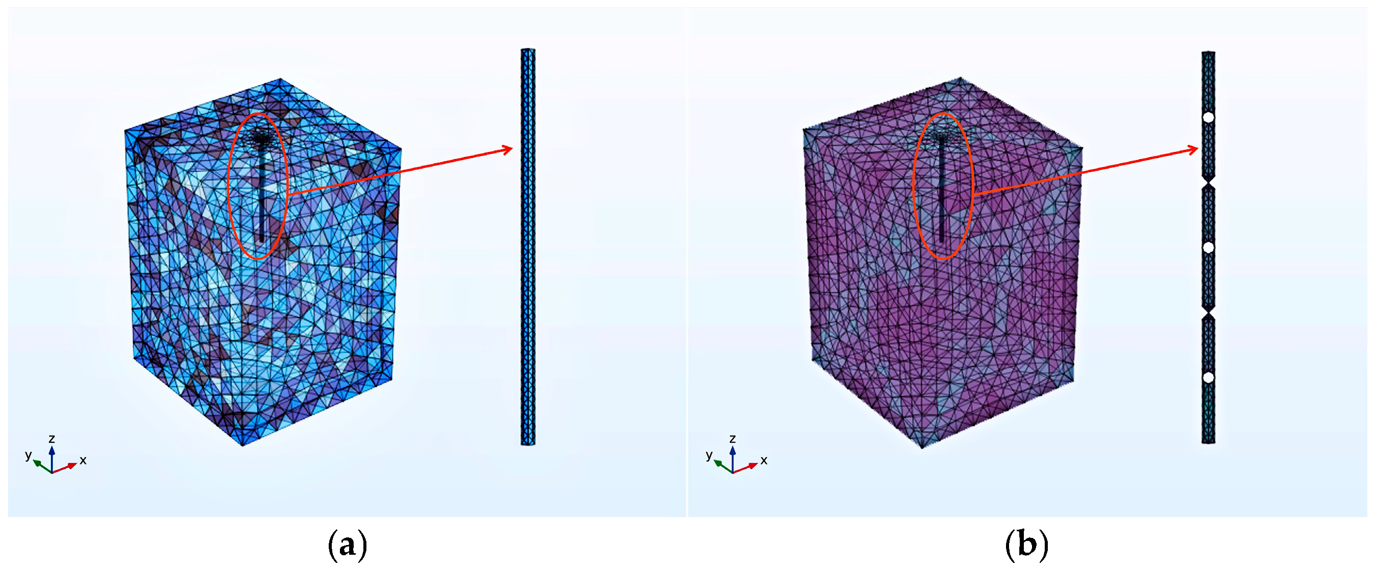
5.1. Creation of Models

Based on experimental results and theoretical calculations, a model with dimensions of 0.8 m × 0.8 m × 1.5 m was constructed. The grouting pipe extended 0.6 m into the stratum. The column grouting pipe had a diameter of 0.025 m, with measurement holes spaced at 0.1 cm intervals. The open hole diameter was 0.01 m, while the ball grouting pipe diameter was 0.02 m, featuring an open bottom. Figure 13 illustrates the grouting model and a schematic representation of the grouting pipe configuration.

5.2. Simulation Results

Numerical simulations of power-law fluid column diffusion and spherical diffusion yielded pressure gradient maps and flow rate gradient maps for power-law slurry column diffusion. The flow-rate gradient maps and the pressure gradient maps are presented below for selected time intervals of 5 s, 10 s, and 15 s.
An examination of Figure 14 and Figure 15 (The purple curve in Figure 14 and Figure 15 represents the direction of slurry diffusion) revealed that as the grouting time increased, both the power-law fluid grouting pressure field and the flow velocity field expanded in all directions over time. The column diffusion cloud resembles an ellipsoid, while the spherical diffusion cloud approximates a sphere. Notably, the maximum grouting pressure reaches 0.4 MPa and the maximum flow velocity attains 2 m/s. These observations corroborate the theoretical and practical trends established in this study.

5.3. Numerical Simulation Results

To investigate the influence of fractal parameters on the spreading of power-law fluid grouting, the grouting volume and the spreading radius were extracted and calculated using software for various slurries and grouting models. The results were subsequently plotted, as illustrated below.
Analysis of Figure 16 and Figure 17 reveals that the radius of power-law fluid grouting increases with grouting time. Additionally, the meander fractal dimension shows a negative correlation with the grouting diffusion radius, while the volume fractal dimension exhibits a positive correlation. Comparing the meandering and volume fractal dimensions at the same time point, the meandering fractal dimension has a greater influence on diffusion. When both dimensions are at their maximum values and the meandering fractal dimension is 1.0, the columnar diffusion distance is 168 mm and the spherical diffusion distance is 216 mm. When the maximum volume fractal dimension is 2.8, the columnar diffusion distance is 192 mm and the spherical diffusion distance is 229 mm. The difference between these measurements shows that the grout radius is 48 mm different from the meander fractal dimension and 37 mm different from the volume fractal dimension, suggesting that the meander fractal dimension parameter is more sensitive. The difference between these measurements shows that the grout radius is 48 mm different from the meander fractal dimension and 37 mm different from the volume fractal dimension, suggesting that the meander fractal dimension parameter is more sensitive. Comparing spherical and columnar diffusion, the range of globular diffusion is larger than that of columnar diffusion under the same fractal dimension.

6. Conclusions

This study establishes spherical and columnar diffusion models for power-law slurry, based on the theory of fractal porous media and the power-law fluid rheological equation. It derives the analytical solution of the diffusion radius and verifies its engineering applicability through experimentation. The primary conclusions are as follows:
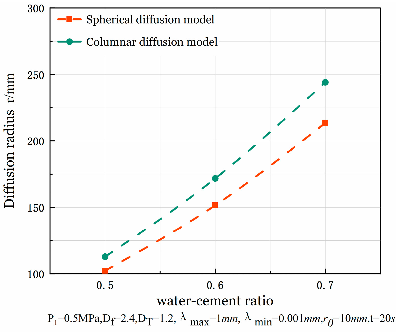
  • The fractal permeability constant exhibits an exponential relationship with the rheological index, demonstrating a threshold effect on its sensitivity. When the rheological index, n, is below 0.4, the influence coefficient of the power index on the fractal permeability is minimal and the fractal permeability constant approaches 0. However, when n exceeds 0.4, the sensitivity increases significantly, with the fractal permeability constant reaching 0.48 at n = 0.9. In the diffusion model study, the pulp diffusion radius shows a non-linear proportional relationship to the slurry pressure and the water–cement ratio. At pressures below 0.1 MPa, the diffusion distance ratio between the spherical and columnar geometries is 1:0.96, indicating limited geometric constraint effects in low-energy grouting. At P = 0.5 MPa, the isotropic advantage of spherical diffusion becomes apparent, with the diffusion distance ratio expanding to 1:0.82. As the water–cement ratio increases from 0.5 to 0.7, the sensitivity of spherical grouting under high water–cement ratios significantly increases, enhancing the penetration efficiency advantage of spherical grouting. Mechanistically, the increase in the water–cement ratio leads to a synergistic decrease in slurry viscosity and yield stress, weakening the shear resistance at the slurry–soil interface and promoting seepage diffusion. This finding aligns closely with the use of high-water–cement ratio slurries for long-distance fissure sealing in engineering practice.
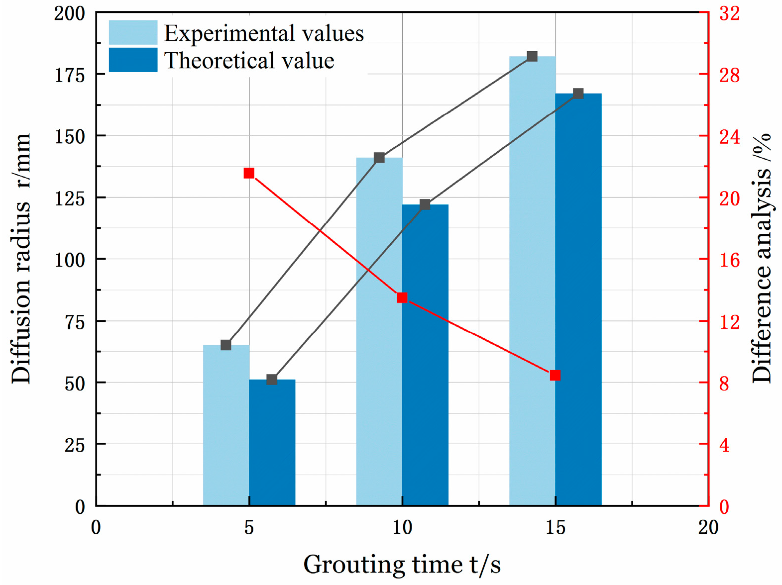
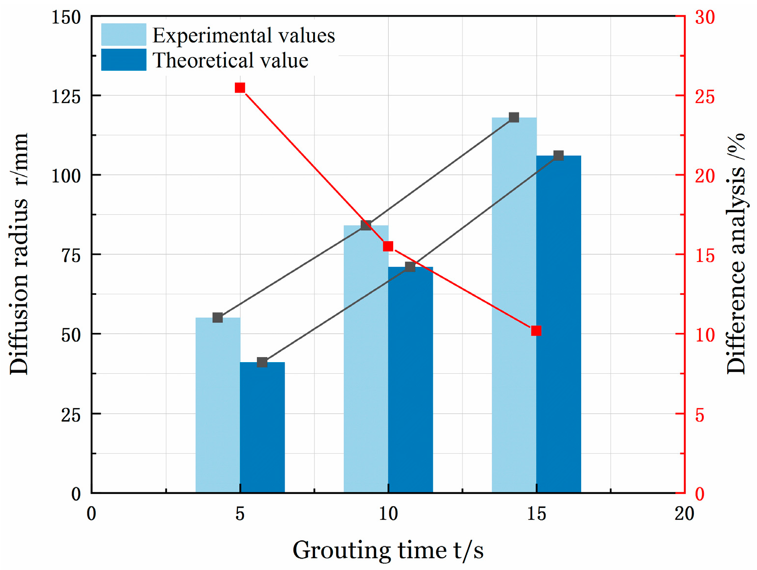
  • In experimental and theoretical studies, the theoretical–experimental error of spherical grouting converged from the initial 21.54% (t = 5 s) to 8.43% (t = 15 s) by exponential decay, while the error of column grouting decreased non-linearly from 25.45% to 10.17%. Despite the above deviations, the errors were located within the engineering tolerance error band (−50%~100%), which proves the engineering applicability of the model. The errors were analyzed mainly from three aspects, neglecting the effect of the pressure-loading dynamic process, geometric constraint and gravity coupling effects, and multi-scale uncertainty sources.
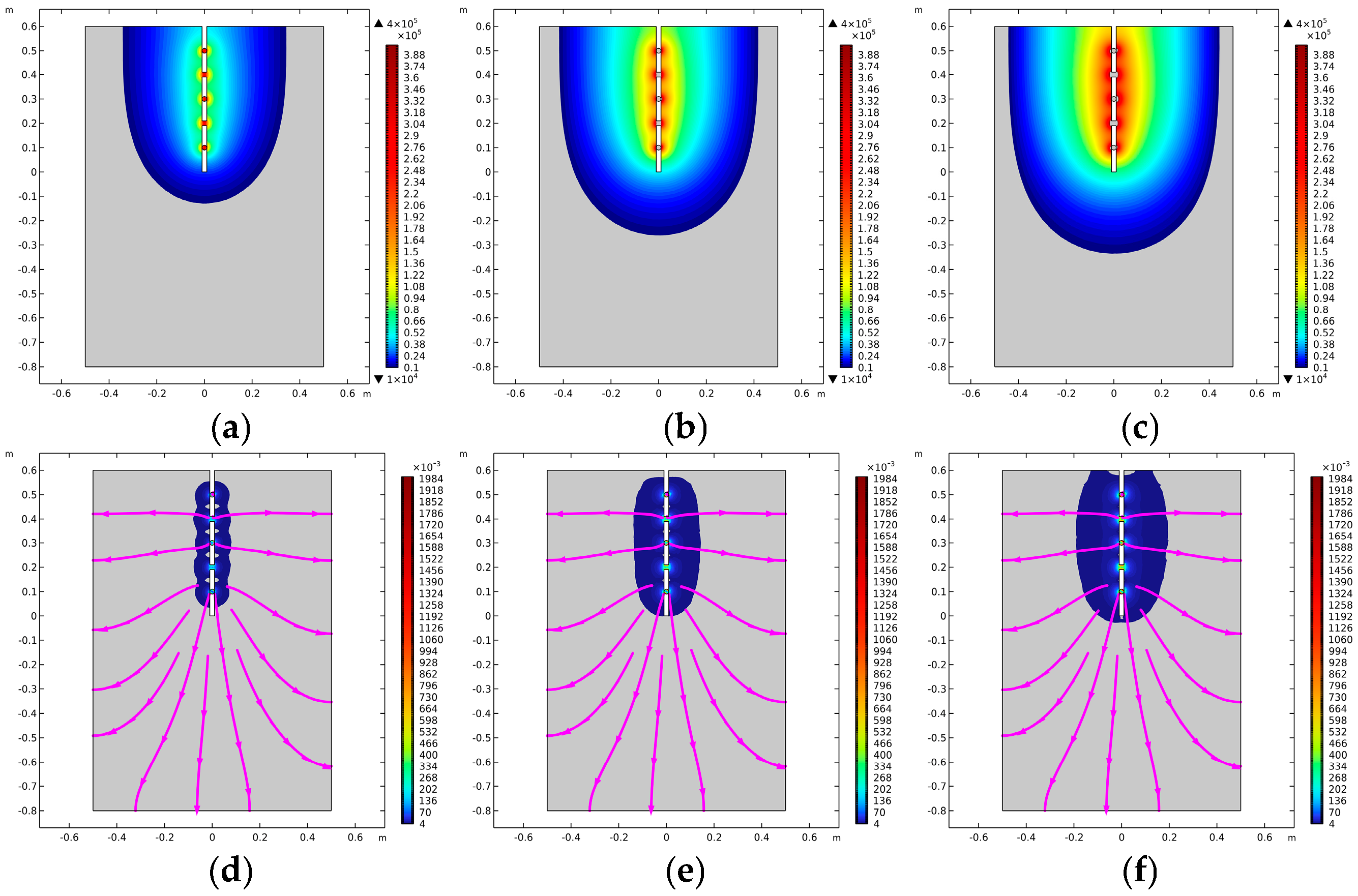
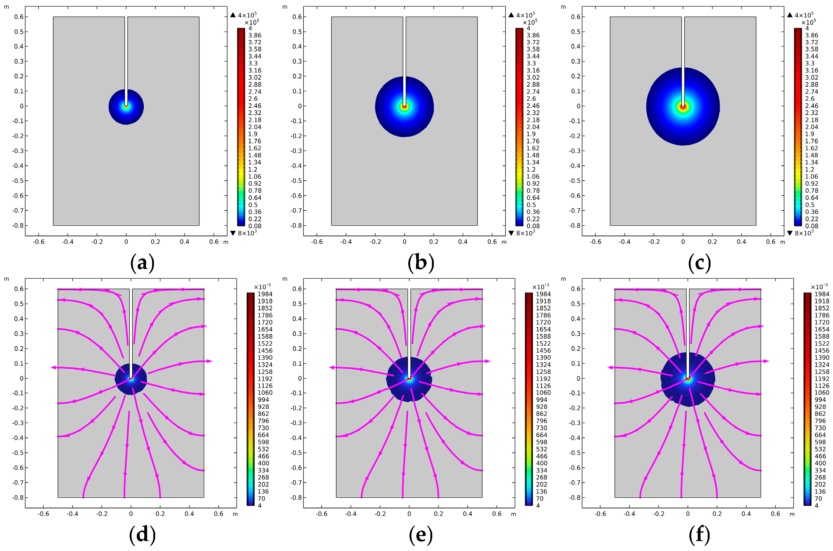
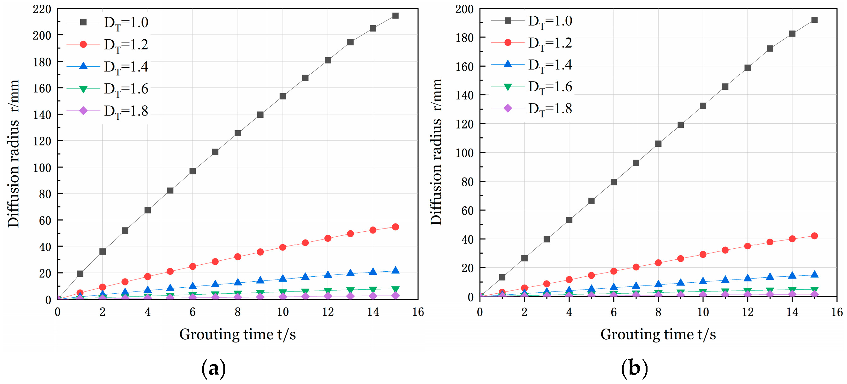
  • Numerical simulation studies reveal that as grouting time increases, the pressure and slurry flow rate of power-law fluid columnar and spherical grouting continuously spread outward. The maximum grouting pressure reaches 0.4 MPa, while the maximum flow rate for both types is 2 m/s. Comparing the meander fractal dimension with the volume fractal dimension, it was observed that when the meander fractal dimension was 1.0, the columnar diffusion distance was 168 mm and the spherical diffusion distance was 216 mm. When the volume fractal dimension was 2.8, the columnar diffusion distance extended to 192 mm and the spherical diffusion distance reached 229 mm. The difference between these two scenarios (48 mm for the meander fractal dimension and 37 mm for the volume fractal dimension) indicates that the meander fractal dimension parameters are more sensitive. Furthermore, comparing spherical and columnar diffusion under the same fractal dimension demonstrates that spherical diffusion consistently exhibits a larger range than columnar diffusion.

Author Contributions

Conceptualization, F.W., J.L. and X.S.; Writing—original draft, F.W. All authors have read and agreed to the published version of the manuscript.

Funding

This research received no external funding.

Data Availability Statement

The original contributions presented in this study are included in the article. Further inquiries can be directed to the corresponding author.

Conflicts of Interest

The authors declare no conflict of interest.

Glossary

SymbolsDefinitions
λ Equivalent diameter
N Total cumulative number of pore areas
λ m a x Maximum pore diameter
D f Volume fractal dimension
τ Degree of tortuosity
L e Effective length of pores
D T Tortuous fractal dimension
L Pore length
τShear stress
C Coefficient of consistency
n Rheological index
μ a Apparent viscosity
q Fluid flow
L e Effective pore length
A 0 Reference area
K c Fractal permeability constant
V p Effective volume of grouting
V b Total volume of the sphere model
ϕ Porosity
Q s Spherical modeling fluid flow
Q c Column modeled fluid flow
V Average flow rate of fluid in a pore
v Average fluid flow rate
A b Ball model grouting area
A p Area of column model grouting
r 0 Grouting pipe radius
r 1 Slurry diffusion radius
p 1 Grouting pressure
p 0 Water head pressure at grouting point
dSpatial geometric dimension
τavAverage tortuosity
λavAverage capillary diameter

References

  1. Yang, Z.Q.; Hou, K.P.; Guo, T.T. Research on Time-Varying Behavior of Cement Grouts of Different Water-Cement Ratios. Appl. Mech. Mater. 2011, 71–78, 4398–4401. [Google Scholar] [CrossRef]
  2. AL-Shahrabalee, S.Q. Brief History and Fundamentals about the Grouting. J. Water Resour. Geosci. 2023, 2, 207–234. [Google Scholar]
  3. Niu, F.; Liu, Y.; Xue, F.; Sun, H.; Liu, T.; He, H.; Kong, X.; Chen, Y.; Liao, H. Ultra-high performance concrete: A review of its material properties and usage in shield tunnel segment. Case Stud. Constr. Mater. 2025, 22, e04194. [Google Scholar]
  4. Tang, K.; Qiu, J.; Lai, J.; Xue, F.; Wang, Z.; Li, X. Experimental investigation on deformation-failure mechanisms of a shallow-bias large-section loess tunnel induced by rainfall. Tunn. Undergr. Space Technol. 2025, 157, 106253. [Google Scholar]
  5. Zahra, Z.S.A. Review on Properties and Applications of Grouting Technique. J. Water Resour. Geosci. 2024, 3, 66–97. [Google Scholar]
  6. Zhou, Y.; Li, W.; Peng, Y.; Tang, S.; Wang, L.; Shi, Y.; Li, Y.; Wang, Y.; Geng, Z.; Wu, K. Hydration and fractal analysis on low-heat portland cement pastes using thermodynamics-based methods. Fractal Fract. 2023, 7, 606. [Google Scholar] [CrossRef]
  7. Guo, T.; Zhang, Z.; Yang, Z.; Zhu, Y.; Yang, Y.; Guo, Y.; Wang, R.; Zhang, B.; Fang, Y.; Yu, D. Penetration grouting mechanism of time-dependent power-law fluid for reinforcing loose gravel soil. Minerals 2021, 11, 1391. [Google Scholar] [CrossRef]
  8. Liu, C.; Zhang, X.; Lai, J.; Qin, Y. Steel fiber-reinforced recycled coarse aggregate shotcrete repair for tunnel lining corrosion: Experimental tests and calculation analysis. Tunn. Undergr. Space Technol. 2025, 157, 106236. [Google Scholar]
  9. Tang, G.; Shang, C.; Qin, Y.; Lai, J. Current Advances in Flame-Retardant Performance of Tunnel Intumescent Fireproof Coatings: A Review. Coatings 2025, 15, 99. [Google Scholar] [CrossRef]
  10. Zenit, R.; Koch, D.L.; Sangani, A.S. Measurements of the average properties of a suspension of bubbles rising in a vertical channel. J. Fluid Mech. 2001, 429, 307–342. [Google Scholar]
  11. Mandelbrot, B. How long is the coast of Britain? Statistical self-similarity and fractional dimension. Science 1967, 156, 636–638. [Google Scholar] [PubMed]
  12. Huang, Z.; Wu, Y.; Zhang, R.; Zhong, W.; Li, S.; Zhang, C.; Zhao, K. Experimental investigation on the grouting characteristics of fractured sandstones under different confining pressures. Geomech. Geophys. Geo-Energy Geo-Resour. 2022, 8, 201. [Google Scholar] [CrossRef]
  13. Zhou, Z.; Du, X.; Wang, S.; Zang, H. Analysis and engineering application investigation of multiple-hole grouting injections into porous media considering filtration effects. Constr. Build. Mater. 2018, 186, 871–883. [Google Scholar]
  14. Hongyuan, F.; Chang, L.; Xueming, D.; Bin, L.; Kejie, Z.; Xiaohua, Z.; Mingrui, D.; Binghan, X.; Shanyong, W. Experimental study on the diffusion characteristics of nonaqueous reactive expansive polymers in sand and gravel media under dynamic water conditions. Tunn. Undergr. Space Technol. 2023, 142, 105433. [Google Scholar]
  15. Zhou, Z.; Cai, X.; Du, X.; Wang, S.; Ma, D.; Zang, H. Strength and filtration stability of cement grouts in porous media. Tunn. Undergr. Space Technol. 2019, 89, 1–9. [Google Scholar]
  16. Sun, X.; Wang, Y.; Liu, H.; Yang, Z.; Ma, H. Development of multivariate-coupled grouting diffusion model for RCC. Constr. Build. Mater. 2024, 435, 136748. [Google Scholar] [CrossRef]
  17. Du, J.; Zhou, A.; Shen, S.-L.; Bu, Y. Fractal-based model for maximum penetration distance of grout slurry flowing through soils with different dry densities. Comput. Geotech. 2022, 141, 104526. [Google Scholar] [CrossRef]
  18. Yao, M.; Liu, Z.; Yang, H.; Dong, S. Characteristics and factors influencing the nonlinear seepage of paste material injected into a fractal-like tree fracture bifurcation network around coal seam boreholes. Phys. Fluids 2025, 37, 013122. [Google Scholar] [CrossRef]
  19. Yang, Z.; Xiong, J.; Zhao, X.; Meng, X.; Wang, S.; Li, R.; Wang, Y.; Chen, M.; He, N.; Yang, Y. Column-hemispherical penetration grouting mechanism for Newtonian fluid considering the tortuosity of porous media. Processes 2023, 11, 1737. [Google Scholar] [CrossRef]
  20. Zhang, Q.; Wang, H.; Liu, R.; Li, S.; Zhang, L.; Zhu, G.; Zhang, L. Infiltration grouting mechanism of porous media considering diffusion paths of grout. Chin. J. Geotech. Eng. 2018, 40, 918–924. [Google Scholar]
  21. Wang, C.; Diao, Y.; Guo, C.; Li, P.; Du, X.; Pan, Y. Two-stage column–hemispherical penetration diffusion model considering porosity tortuosity and time-dependent viscosity behavior. Acta Geotech. 2023, 18, 2661–2680. [Google Scholar]
  22. Yang, X.; Liang, Y.; Chen, W. A fractal roughness model for the transport of fractional non-Newtonian fluid in microtubes. Chaos Solitons Fractals 2019, 126, 236–241. [Google Scholar]
  23. Xu, B.; Zhang, H.; Yin, J.; Xue, Y. Infiltration Grouting Mechanism of Bingham Fluids in Porous Media with Different Particle Size Distributions. Appl. Sci. 2023, 13, 11986. [Google Scholar] [CrossRef]
  24. Wang, H.; Dong, L.; Zhang, Q.; Li, Z.; Zhang, P. Permeation grouting mechanism of viscous time-varying fluid considering diffusion path. Front. Earth Sci. 2023, 10, 1100196. [Google Scholar]
  25. Wang, H.; Yu, Y.; Zhang, P.; Yang, C.; Wen, H.; Zhang, F.; Du, S. Study on the diffusion mechanism of infiltration grouting in fault fracture zone considering the time-varying characteristics of slurry viscosity under seawater environment. Int. J. Concr. Struct. Mater. 2024, 18, 65. [Google Scholar]
  26. Zhou, F.; Wei, F.; Yang, S. Based on the fractal seepage theory Bingham-type slurry column diffusion model. Tunn. Constr. 2024, 44, 1356–1364. (In Chinese) [Google Scholar]
  27. Wang, S.; Wu, T.; Su, Y. A Fractal Permeability Model for the Power-law Fluid Spherical Flow in Porous Media. J. Hubei Univ. Educ. 2021. (In Chinese) [Google Scholar]
  28. Wang, S.; Wu, T.; Zheng, Q. A Fractal Permeability Model for the Power Law Fluid Radial Flow in a Well in a Porous Medium. Chin. Q. Mech. 2016, 37, 7. (In Chinese) [Google Scholar]
  29. Zhang, B.; Yu, B.; Wang, H.; Yun, M. A fractal analysis of permeability for power-law fluids in porous media. Fractals 2006, 14, 171–177. [Google Scholar]
  30. Li, W.; Kou, L.; Sun, M.; Wang, Y.; Shi, X.; Liang, H. Fractal Analysis of Effective Permeability for Power-Law Fluid in Porous Media with Effective Pore Radius. Arab. J. Sci. Eng. 2024, 49, 9747–9756. [Google Scholar]
  31. Xiao, B.; Li, Y.; Long, G.; Yu, B. Fractal permeability model for power-law fluids in fractured porous media with rough surfaces. Fractals 2022, 30, 2250115. [Google Scholar]
  32. Yun, M. Seepage Characteristics Study on Power-Law Fluid in Fractal Porous Media. Math. Probl. Eng. 2014, 2014, 813561. [Google Scholar]
  33. Yang, Z.; Lu, J.; Wang, Y.; Zhang, Z.; Yang, Y.; Zhu, Y.; Zhang, J.; Guo, Y.; Chen, X. Column penetration grouting mechanism for power-law fluids considering tortuosity effect of porous media. Chin. J. Rock Mech. Eng. 2021, 40, 410–418. (In Chinese) [Google Scholar] [CrossRef]
  34. Wu, T.; Li, G. A fractal model of permeability for power-law fluids in porous-fracture dual media. J. Hua Zhong Norm. Univers 2021, 55, 376–381. [Google Scholar]
  35. Xu, P.; Yu, B. Developing a new form of permeability and Kozeny–Carman constant for homogeneous porous media by means of fractal geometry. Adv. Water Resour. 2008, 31, 74–81. [Google Scholar]
  36. Xu, P.; Yu, B.; Qiao, X.; Qiu, S.; Jiang, Z. Radial permeability of fractured porous media by Monte Carlo simulations. Int. J. Heat Mass Transf. 2013, 57, 369–374. [Google Scholar]
  37. Yang, S.; Liang, M.; Yu, B.; Zou, M. Permeability model for fractal porous media with rough surfaces. Microfluid. Nanofluidics 2015, 18, 1085–1093. [Google Scholar]
  38. Huang, J.; Li, W.; Huang, D.; Wang, L.; Chen, E.; Wu, C.; Wang, B.; Deng, H.; Tang, S.; Shi, Y. Fractal analysis on pore structure and hydration of magnesium oxysulfate cements by first principle, thermodynamic and microstructure-based methods. Fractal Fract. 2021, 5, 164. [Google Scholar] [CrossRef]
  39. Majumdar, A.; Bhushan, B. Role of fractal geometry in roughness characterization and contact mechanics of surfaces. J. Tribol. 1990, 112, 205–216. [Google Scholar]
  40. Wenjun, R. Research on diffusion of grouting and basic properties of grouts. Chin. J. Geotech. Eng. 2005, 27, 69–73. [Google Scholar]
  41. Yu, W.; Zhou, Y.; Zhao, Z.; Li, Y.; Long, Y.; Tang, S. Simulation of low-heat Portland cement permeability and thermal conductivity using thermodynamics. Proc. Inst. Civ. Eng. Transp. 2024, in press. [Google Scholar]
  42. Govier, G.W.; Aziz, K.; Schowalter, W. The flow of complex mixtures in pipes. J. Appl. Mech. 1973, 40, 404. [Google Scholar]
  43. Bo-Ming, Y. Fractal Character for Tortuous Streamtubes in Porous Media. Chin. Phys. Lett. 2005, 22, 3. [Google Scholar]
  44. Yu, B.; Li, J. Some fractal characters of porous media. Fractals 2001, 9, 365–372. [Google Scholar]
  45. Bo-Ming, Y.; Jian-Hua, L. A geometry model for tortuosity of flow path in porous media. Chin. Phys. Lett. 2004, 21, 1569. [Google Scholar]
  46. Wei, Y.; Kong, W.; Wang, Y.; Sha, A. Multifunctional application of nanoscratch technique to characterize cementitious materials. Cem. Concr. Res. 2021, 140, 106318. [Google Scholar]
  47. Kong Luzhi, D.J. Time dependent analysis of rheological parameters of cement slurry. In Proceedings of the 9th Slope Engineering Conference 2017, Ningbo, China, 24–27 October 2017; p. 4. (In Chinese). [Google Scholar]
  48. Wei, Y.; Liang, S.; Gao, X. Phase quantification in cementitious materials by dynamic modulus mapping. Mater. Charact. 2017, 127, 348–356. [Google Scholar]
Figure 1. Porous media model. (a) Simplified porous media pore channels. (b) Actual porous media pore channels.
Buildings 15 00987 g001
Figure 2. Schematic diagram of spherical diffusion of slurry.
Buildings 15 00987 g002
Figure 3. Schematic diagram of slurry column diffusion.
Buildings 15 00987 g003
Figure 4. The variation law of the fractal permeability constant with rheological index.
Buildings 15 00987 g004
Figure 5. Variation law of diffusion radius with grouting pressure.
Buildings 15 00987 g005
Figure 6. Variation law of diffusion radius with water–cement ratio.
Buildings 15 00987 g006
Figure 7. Experimental equipment. (a) Grouting machine. (b) Mixer. (c) Laboratory kit. (d) Porous media sample.
Buildings 15 00987 g007
Figure 8. Grouting pipe. (a) Physical picture of grouting pipe. (b) Schematic diagram of grouting pipe.
Buildings 15 00987 g008aBuildings 15 00987 g008b
Figure 9. Pixel map of the injected medium.
Buildings 15 00987 g009
Figure 10. Experimental measurement results. (a) K1. (b) K2. (c) K3. (d) S1. (e) S2. (f) S3.
Buildings 15 00987 g010
Figure 11. Experimental and theoretical calculation analysis of spherical grouting.
Buildings 15 00987 g011
Figure 12. Analysis of column grouting experiment and theoretical calculation.
Buildings 15 00987 g012
Figure 13. Schematic diagram of grouting model and grouting pipe modeling. (a) Spherical grouting model. (b) Column grouting model.
Buildings 15 00987 g013
Figure 14. Power-law fluid cylindrical grouting diffusion cloud map. (a) Pressure cloud at 5 s. (b) Pressure cloud at 10 s. (c) Pressure cloud at 15 s. (d) Cloud view of flow rate at 5 s. (e) Cloud view of flow rate at 10 s. (f) Cloud view of flow rate at 15 s.
Buildings 15 00987 g014
Figure 15. Cloud diagram of spherical injection diffusion of power-law fluid. (a) Pressure cloud at 5 s. (b) Pressure cloud at 10 s. (c) Pressure cloud at 15 s. (d) Cloud view of flow rate at 5 s. (e) Cloud view of flow rate at 10 s. (f) Cloud view of flow rate at 15 s.
Buildings 15 00987 g015
Figure 16. The influence of different fractal dimensions of tortuosity on the diffusion of power-law fluid injection. (a) Spherical grout diffusion results. (b) Column grouting model.
Buildings 15 00987 g016
Figure 17. The influence of different volume fractal dimensions on the diffusion of power-law fluid injection. (a) Spherical grout diffusion results. (b) Column grouting model.
Buildings 15 00987 g017
Table 1. Water–cement ratio rheological characteristics of power-law cement slurry.
Rheological Characteristics W / C = 0.5 W / C = 0.6 W / C = 0.7
Coefficient of consistency6.4753.2461.569
Rheological index0.3240.3300.308
Apparent viscosity0.3140.0720.028
Rheological equation τ = 6.474 γ 0.324 τ = 3.246 γ 0.330 τ = 6.474 γ 0.308
Table 2. Index parameters of injected materials.
Parameter CategoryCoarse Sand
Experimental measurement indexPorosity, ϕ/ %41.80
Maximum pore diameter, λ m a x / m m 0.43
Derived calculated indicators Average tortuosity, τav2.07
Average capillary diameter, λ m a x / m m 0.0072
Volume dimension, Df2.4596
Table 3. Experimental results and theoretical calculation results.
Serial NumberExperimental ValuesTheoretical ValuesDifference Analysis
%
Measured Grouting Pressure Value
P 1 / MPa
Grouting Time
t / s
Experimental Diffusion Radius
r 1 / mm
Tortuous Fractal Dimension (Math.)
D T
Calculated Diffusion Grouting r 1 / mm
K10.4185651.1025 48 26.15
K20.389101441.0995 128 11.11
K30.394151821.0977 167 8.43
S10.3925551.0700 41 25.45
S20.40810841.0682 71 15.48
S30.407151181.0670 106 10.17
Disclaimer/Publisher’s Note: The statements, opinions and data contained in all publications are solely those of the individual author(s) and contributor(s) and not of MDPI and/or the editor(s). MDPI and/or the editor(s) disclaim responsibility for any injury to people or property resulting from any ideas, methods, instructions or products referred to in the content.

