Article

The Impact of Manufacturing Technology on the Tube-Steel Concrete Columns Bearing Capacity Under Axial Load

by
Evgenii M. Shcherban’
1,
Alexey N. Beskopylny
2,*,
Sergei A. Stel’makh
3,
Levon R. Mailyan
3,
Ivan A. Panfilov
4,
Alexander L. Mailyan
5,
Natalya Shcherban’
3,
Ivan Vialikov
6,
Diana Elshaeva
3 and
Andrei Chernilnik
3
1
Department of Engineering Geometry and Computer Graphics, Don State Technical University, 344003 Rostov-on-Don, Russia
2
Department of Transport Systems, Faculty of Roads and Transport Systems, Don State Technical University, 344003 Rostov-on-Don, Russia
3
Department of Unique Buildings and Constructions Engineering, Don State Technical University, 344003 Rostov-on-Don, Russia
4
Department of Theoretical and Applied Mechanics, Agribusiness Faculty, Don State Technical University, Gagarin, 1, 344003 Rostov-on-Don, Russia
5
Department of Urban Construction and Economy, Don State Technical University, 344003 Rostov-on-Don, Russia
6
School of Architecture, Design and Arts, Don State Technical University, 344003 Rostov-on-Don, Russia
*
Author to whom correspondence should be addressed.
Buildings 2025, 15(6), 950; https://doi.org/10.3390/buildings15060950
Submission received: 23 February 2025 / Revised: 15 March 2025 / Accepted: 17 March 2025 / Published: 18 March 2025
(This article belongs to the Section Building Materials, and Repair & Renovation)

Abstract

Current construction puts forward new requirements for the construction of important buildings and structures every year. In this regard, new approaches to the design of buildings and structures using modern types of structural elements should take priority, which includes the vibrocentrifuged tube concrete columns. The purpose of this study is to evaluate the efficiency of manufacturing tube concrete columns using vibration (V), centrifugation (C), and vibrocentrifugation (VC) technologies and to perform a comparative analysis with the bearing capacity of solid tube concrete columns. Compositions of concrete grades B25, B30 and B40 were developed and manufactured using V, C and VC technologies. The greatest compressive strength was recorded for vibrocentrifuged concrete. Three samples of solid tube concrete columns and nine samples of hollow tube concrete columns were made from these concrete types. It was found that VC tube concrete columns have the highest bearing capacity values, which are up to 30.4% greater than those of vibrated columns, up to 15.1% greater than those of centrifuged hollow tube concrete columns, and up to 12.9% greater than those of vibrated solid tube concrete columns. It was proven that the use of vibrocentrifugation technology allows for the reduction in the weight of concrete pipe structures because of the hollow concrete core and the increase in the load-bearing capacity because of the high compression of the concrete core by the steel casing pipe.

1. Introduction

Current construction puts forward new complex requirements for the construction of important buildings and structures every year. The increasing complexity of the constructed objects is combined with difficult climatic and geological conditions [1,2,3]. In this regard, fundamentally novel approaches to the design of buildings and structures come to the fore. The solution to this task lies in preparing scientific foundations and developing engineering applications for new improved and universal types of structures and technologies for their use in the construction [4,5,6,7]. Nowadays, there are many engineering solutions that are aimed at increasing the reliability of the construction of buildings and structures. However, the insufficient scientific basis in design solutions often leads to unnecessary expenses in materials, labor, time and resources, reflecting scientific deficiencies [8].
Steel columns filled with concrete are an example of an effective design solution. The steel shell constrains the concrete core, and reciprocally, the concrete core inhibits localized buckling of the steel shell. Using various formulation and technological methods in the manufacture of tubular columns allows for the increase in their load-bearing and deformation capacity [9]. For example, in [10], various types of fiber concrete with steel, carbon, glass, coconut, jute and sisal fibers were used to manufacture tubular concrete columns. Strength and ductility tests revealed the superiority of fiber concrete-filled columns over conventional ones. The bearing capacity demonstrated an increase of up to 203.88%. Using coarse recycled filler and basalt fiber in tubular concrete columns did not have a significant effect on the change in their bearing capacity, but an increase in plasticity was observed [11,12]. Tubular steel–concrete structures reinforced with steel fiber had a higher bearing capacity and seismic characteristics [13,14,15,16]. The inclusion of rubber crumb in the concrete composition increased the strength and plasticity indices of tubular concrete columns by 10% and 30%, respectively, but the strength of the concrete core itself decreased [17,18]. An effective technological solution is the application of corrugated steel tubes instead of flat ones in the manufacture of tubular columns [19,20]. Manufacturing tubular concrete columns by a non-standard method of centrifugal compaction made it possible to improve their properties [21]. In the world scientific literature on the topic of tubular concrete products, a significant number of studies are devoted to the numerical modeling of the properties of such products under various types of loads and operating conditions. The finite element method made it possible to develop models that simulate, with high accuracy, the axial load on tubular concrete columns and their properties under these loads [22,23]. Models have been developed that make it possible to simulate the behavior of tubular concrete columns under seismic loads [24,25]. As new approaches for the more accurate assessment of resistance of tubular columns to axial compression were developed, the use of hybrid fuzzy systems with differential evolution and firefly algorithm methods was proposed [26]. Artificial neural networks are also a promising tool for predicting the bearing capacity of tubular columns [27,28,29,30,31]. In addition to modeling the main mechanical properties of tubular concrete structures, forecasting their non-standard properties is also of interest. For example, the use of special piezoelectric intelligent sensors allows for effective monitoring of the condition of tubular columns under impact loads [32]. The finite element method allows for the modeling of the dynamic analysis of elliptical tubular concrete elements under lateral impact load [33]. Furthermore, a novel method for predicting the ultimate strength of tubular concrete columns following chloride salt corrosion exposure is presented [34]. Of particular interest are studies devoted to the axial compression behavior of columns made of steel pipes filled with concrete and steel pipes of various shapes and configurations [35,36], including those operating in seismically hazardous regions [37].
However, the construction industry struggles with inconsistent tube concrete element standards and difficult installation due to their considerable weight [1,2,21]. This study takes as a basis the standard technology for producing tube concrete structures and improves the technology for producing new structures with maximum cost reduction and increased efficiency of both design and technological solutions related to tube concrete structures [38,39,40,41]. A gap in the existing research is the lack of information on non-standard technologies for producing tube concrete products and structures that are ready to compete with conventional vibration technology. A review of previous studies revealed a shortage of research considering centrifugal technology for manufacturing tube concrete elements [21]. Unlike the few previous works, this study proposes a new improved rational type of low-material-intensive lightweight vibrocentrifuged hollow tube concrete columns that are efficient and superior to tube concrete columns manufactured using standard vibration technology.
The main aim of this study is to evaluate the efficiency of manufacturing hollow tube concrete columns using vibration (V), centrifugation (C) and vibrocentrifugation (VC) technologies, and to perform a comparative analysis of their bearing capacity with the bearing capacity of solid tube concrete columns.
The objectives of the study are
-
the selection of the composition of vibrated, centrifuged and vibrocentrifuged concrete;
-
manufacturing, testing and evaluating the properties of experimental samples of V, C and VC concrete technology;
-
manufacturing laboratory prototypes of solid and hollow tube concrete columns from vibrated, centrifuged and vibrocentrifuged concrete;
-
preparation, implementation and analysis of experimental results;
-
the evaluation of the efficiency of hollow tube concrete columns manufactured using different technologies under load by comparing the ratios of the actual and calculated bearing capacity.
From a scientific point of view, the creation of new vibrocentrifuged tube concrete columns with a variatropic structure of the concrete core will allow us to study the influence of technology, formulation and composition of the concrete core on the characteristics of concrete, as well as on the bearing capacity of tube concrete columns obtained in this way.

2. Materials and Methods

2.1. Materials

For the tubular concrete columns producing, steel casing tubes manufactured by Chelyabinsk Profile Tube Plant LLC (Chelyabinsk, Russia) with an external diameter of 102 mm, a wall thickness of 3 mm and a height of 1000 mm were used. The steel of the casing tubes has the following characteristics: grade 10G2 (GOST 1577-2022 [42]), tensile strength—420 MPa, yield strength—295 MPa; relative elongation after rupture—22%, density—7790 kg/m3. Concrete for the production of tubular concrete columns was adopted as grades B25, B30 and B40, as the most rational for structures of this type. These concrete grades are equivalent to the designations C25, C30 and C40 for a cubic specimen, respectively. These grades of concrete are characterized by a completely accessible recipe and production technology. The composition of concrete in vibrated, centrifuged and vibrocentrifuged samples varied because of the technological features of each production method. The design of the compositions was carried out based on the principle of the same concrete grades for each technology. The experimental sample sizes of composite columns were calculated from the full-scale composite column, the dimensions of which were taken from the regulatory document (Appendix A in [43]), considering the maximum permissible height of the laboratory specimen, fixed in a special testing installation to determine its bearing capacity under an axial load.
Concrete was manufactured using the following raw materials:
-
Portland cement CEM I 42.5H (PC) (Sebryakovcement, Mikhailovka, Russia).
-
Granite crushed stone (CrS) (Pavlovsk Nerud, Pavlovsk, Russia).
-
Quartz sand (QS) (Erofeevsky sand quarry, Erofeevka, Russia).
The physical and mechanical properties of the raw materials provided by the manufacturers are shown in Table 1, and their granulometric composition is shown in Figure 1.
Figure 1a illustrates that the crushed stone’s particle size fraction is between 5 and 20 mm; Figure 1b indicates a fineness modulus of 1.83 for the quartz sand.

2.2. Methods

The experimental study included the following main stages.
Stage 1. First, the compositions of mixtures intended for the production of concrete using vibration and centrifugal compaction technologies were developed. Then, the characteristics of the fresh concrete were assessed; in particular, its density and slump.
Stage 2. Concrete samples were produced using V, C and VC technologies.
Stage 3. The properties of vibrated (VC), centrifuged (CC) and vibrocentrifuged (VCC) concrete were assessed, such as density, compressive strength (cubic strength), axial compressive strength (prismatic strength) and modulus of elasticity.
Stage 4. Solid tube concrete columns were produced using V technology and hollow tube concrete columns were produced using V, C and VC technologies.
Stage 5. Experimental tube concrete columns were tested for central compression and a comparative analysis of the obtained data was carried out.
For manufacturing tube concrete columns using V, C and VC technologies, concrete mixes of design grades B25, B30 and B40 with workability grade P1 were produced, the compositions of which are presented in Table 2. The selection of concrete composition for vibration technology was carried out according to the method [44]. The composition of the concrete mixture for the centrifugal compaction technology was calculated using the method [45].
Differences in the concrete mixes’ compositions intended for producing concrete using vibration and centrifugal compaction technologies arise because of differences in the methods of selecting and calculating the composition and technological features of molding. Higher cement content distinguishes the concrete mixes designed for centrifugal compaction. During centrifugal compaction of the concrete mix, the process of squeezing water from the upper layers of concrete to the lower ones occurs. A cement mix comprising water and a fine fraction of cement is formed. Once molding is finished, the excess mix is removed, resulting in some cement loss from the total concrete volume. Therefore, initially, more cement must be added to concrete mixes for centrifugal compaction to ensure the required strength. The compositions of concrete mixes presented in Table 2 are selected, taking into account the features of various manufacturing technologies (VC, CC and VCC) and ensuring the required strength properties of the concrete and products made from it.
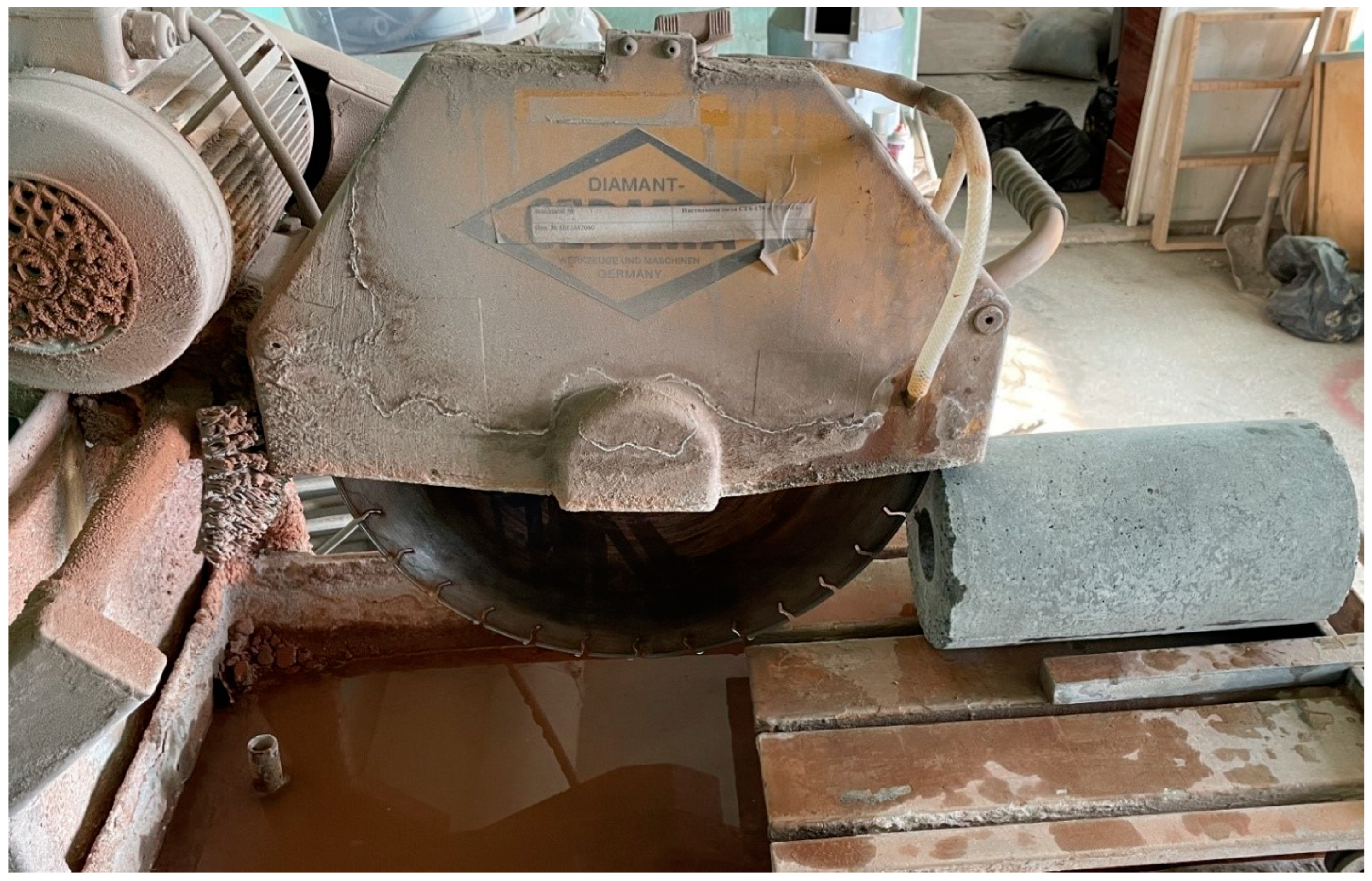
Concrete mixes for all types of concrete were prepared identically. Raw components dosed according to the recipe were loaded into a lab concrete mixer, BL-10. Cement and sand were poured in and mixed dry for 60 s. After that, mixing water was added, and all components were mixed until a homogeneous mixture was obtained. In the final phase, crushed stone aggregate was incorporated, the concrete mixture was homogenized, and subsequently discharged from the mixer for further application. The experimental samples were manufactured using vibration technology as follows. The finished concrete mixture was poured into metal cube molds and prism molds with dimensions of 100 × 100 × 100 mm and 100 × 100 × 400 mm, respectively. After that, the molds were placed on a laboratory vibration platform and compacted for 60 s. The surface of the finished samples was smoothed and leveled. The samples were cured in a KNT-1 normal curing chamber. After 24 h, the specimens were removed from the molds and cured for the remaining 27 days in a normal curing chamber at a temperature of 20 ± 2 °C and a relative air humidity of 95 ± 5%. Centrifuged and vibrocentrifuged concrete samples were manufactured using a special laboratory setup [46] (DSTU, Rostov-on-Don, Russia). The finished concrete mix was poured into special metal molds for centrifugal compaction, which were then placed on the setup. Centrifugation was carried out with the following parameters: rotation speed of 800 rpm, centrifugal compaction duration of 8 min; vibrocentrifugation: rotation speed of 800 rpm, centrifugal compaction duration of 8 min; height of technological protrusions of the clamps 5 mm; the length of the technological projections of the stirrups is 10 mm; the step between the technological projections of the stirrups is 10 mm. After compaction, the samples were kept in the forms for one day, and then stripped and placed in a normal hardening chamber during the same time and under the same conditions as the samples manufactured using the vibration technology. After 28 days of hardening, the centrifuged and vibrocentrifuged concrete samples were sawn on a CTS-175 CEDIMA stone-cutting machine (CEDIMA, Celle, Germany) (Figure 2) according to the diagram [47].
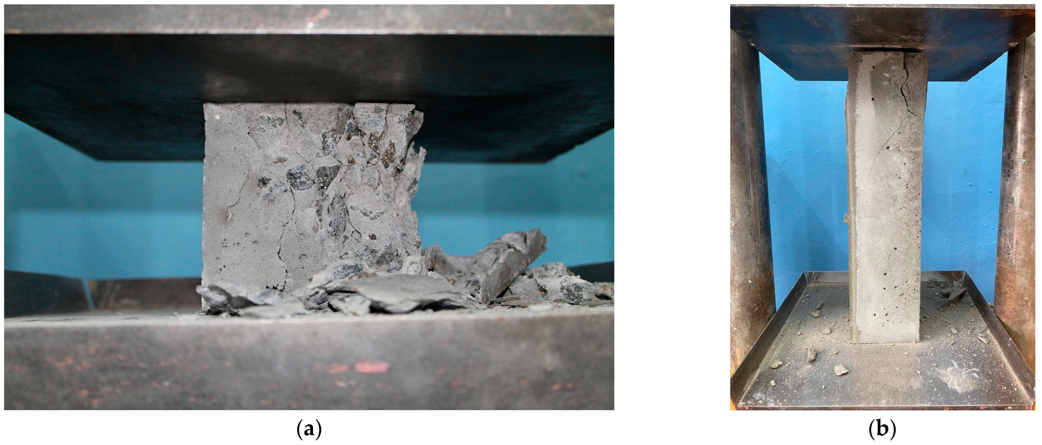
A total of 2 base samples were made—centrifuged and vibrocentrifuged—for each concrete grade by compressive strength—B25, B30 and B40 (outer diameter 300 mm; inner diameter 70 mm; height 500 mm). From each base sample, 3 cubes and 3 prisms were cut. From the centrifuged and vibrocentrifuged base samples, a total of eighteen elements were excised: nine cubes and nine prisms. A total of 54 samples (27 cubes and 27 prisms) were prepared for concrete compression testing. The properties of concrete were assessed on laboratory samples according to Figure 3.
The density of concrete cube samples was assessed in accordance with the requirements of the methodology [48] and calculated using the formula:
ρ c = m V × 1000
Here, m is the mass of the sample (g); V is the volume of the sample (cm3).
Compressive strength was determined in accordance with the requirements of the methods [49,50,51,52,53]. All specimens were tested on a Press P-50 hydraulic press at a constant load increase rate of (0.6 ± 0.2) MPa/s. A calculation of compressive strength was performed using the formula:
R = α F A
Here, F is the breaking load (N); A is the area of the working cross-section of the specimen (mm2); α is the scaling factor for converting the concrete strength to the strength of concrete in specimens of the basic size and shape (for cube specimens with an edge length of 100 mm, it is equal to α = 0.95).
The axial compressive strength and the modulus of elasticity were determined in accordance with the requirements of the method [54]. All prism samples with pre-installed fixtures for measuring deformations were placed in the Press P-50 installation (PKC ZIM, Armavir, Russia). To determine the prismatic compressive strength and the modulus of elasticity, the specimens were initially loaded to a load level equal to (40 ± 5)% Pp. The loading was performed in steps equal to 10% of the expected breaking load at a constant loading rate of (0.6 ± 2) MPa/s. At each step, the load was maintained for 4 to 5 min. At a load level equal to (40 ± 5)% Pp, the instruments for measuring deformations were removed from the samples. Then, loading was carried out until the sample was completely destroyed. The axial compression strength was calculated using the formula:
R b = P p A
Here, Pp is the breaking load (N); A is the working cross-sectional area of the sample (mm2). The modulus of elasticity was calculated at a load level of 30% of the breaking load using the formula:
E σ = σ 1 ε 1 y
Here, σ 1 = P 1 F is the stress increment from the conditional zero to the external load level equal to 30% of the destructive load; P1 is the corresponding external load increment; ε 1 y is the increment of the elastic-instantaneous relative longitudinal deformation of the sample corresponding to the load level P 1 = 0.3 P p , and measured at the beginning of each stage of its application.
The solid tube concrete column was manufactured as follows. First, a tight rubber plug was put on the lower part of the steel casing tube. Then, the casing tube was installed in a vertical position and filled with a concrete mix. During the process of pouring the concrete mix into the tube, it was periodically tapped with a reinforcing bar to ensure a denser placement of the mix. The casing tube filled with concrete mix was installed in a vertical position on a vibration platform and the vibration compaction process was carried out. The manufacturing process of the hollow vibrated column was different in that a special device was used to create the internal cavity, which consisted of a plastic tube with a diameter of 32 mm and two rubber plugs with holes with diameters corresponding to the diameter of the plastic tube. First, a tight rubber plug with a hole for the plastic tube was put on the lower part of the casing tube. Then, the plastic tube, lubricated with a special lubricating fluid, was inserted from the opposite side and tightly fixed in the plug. The casing tube was installed vertically and filled with a concrete mix, which was also periodically bayoneted with a metal rod. After pouring the concrete mix, a plug was put on the upper part of the casing tube. The hollow column was compacted on a vibrating platform with the same parameters as for a solid column. In this case, the use of a plastic tube to create a cavity inside the column, manufactured using vibration technology, was a specialized technological method and did not affect the final properties of hollow tube concrete columns. The plastic tube was securely fixed and did not shift during the compaction process.
The preparation of hollow columns for centrifugation and vibrocentrifugation was performed similarly to the vibrated hollow one. The process of centrifugation and vibrocentrifugation of hollow tube concrete columns was carried out according to the same parameters as the basic centrifuged and vibrocentrifuged concrete samples. After production, all types of tube concrete columns were kept under normal conditions for 28 days (temperature 20 ± 2 °C and relative air humidity 95 ± 5%). A total of 12 samples of tube concrete columns were produced, of which 3 were vibrated solid tube concrete columns, 3 were vibrated hollow tube concrete columns, 3 were centrifuged hollow tube concrete columns, and 3 were vibrocentrifuged hollow tube concrete columns (Table 3).
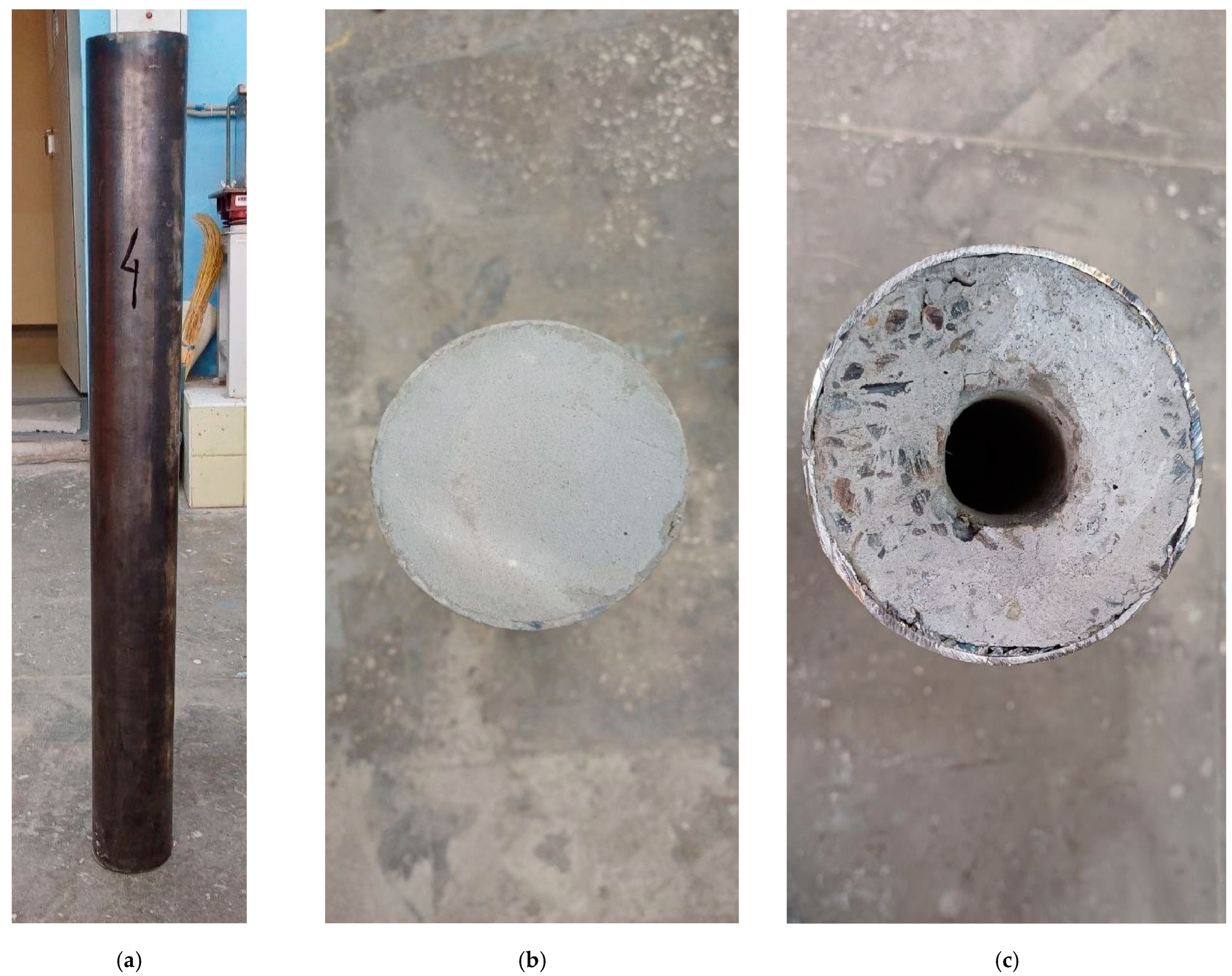
The appearance of the manufactured hollow tube concrete column is shown in Figure 4.
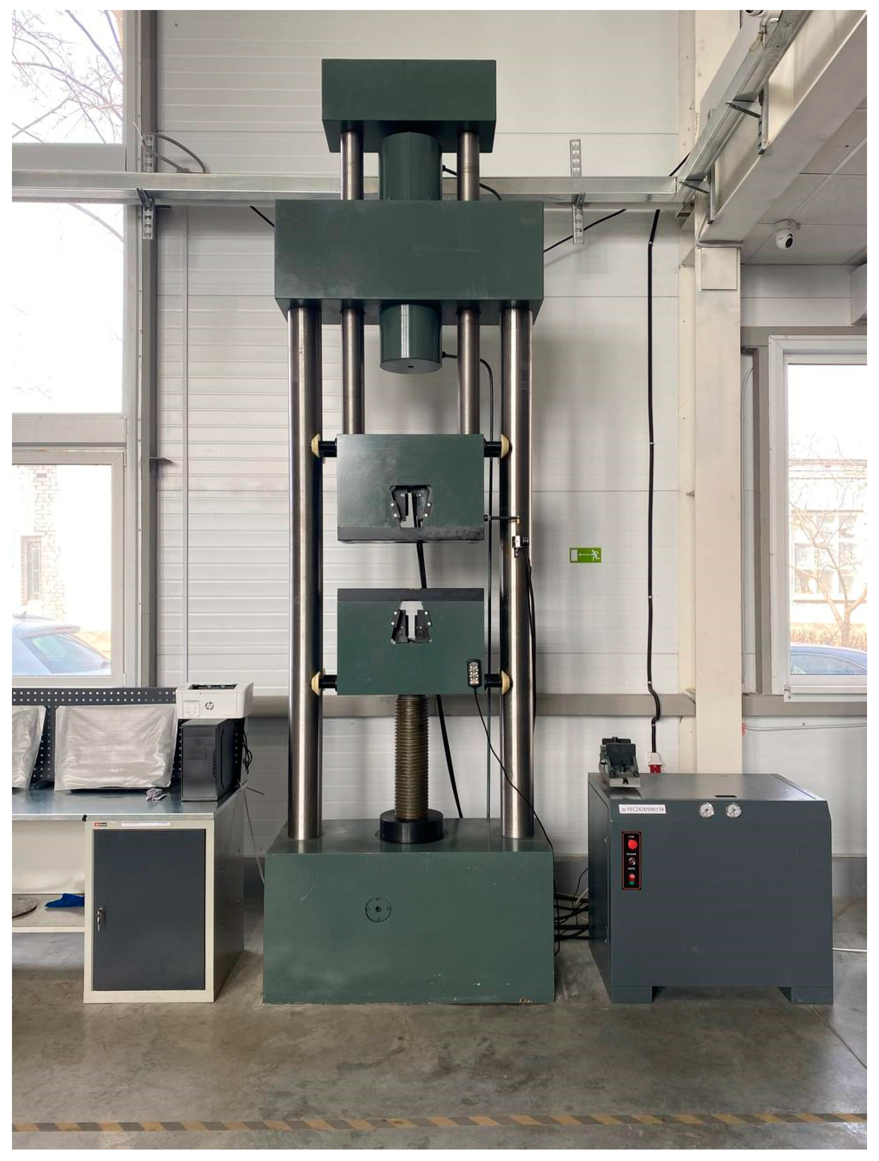
The central compression testing of the experimental specimens of tube-steel concrete columns was carried out on a special laboratory setup (Figure 5). The tube-steel concrete columns were placed in the setup and test loading was carried out in order to check the instruments. After these conditions were met, the tube-steel concrete column was loaded in stages, with holding at each stage and readings taken from the control and measuring instruments. The load step should not exceed 10% of the expected destructive load. During the tests, the load was transferred to the concrete and the steel shell. In this way, the actual bearing capacity of the tube-steel–concrete column specimens ( N exp ) was determined.

2.3. FEM Modeling

The ANSYS (Workbebch 2024 R2) software package was used to model the stress–strain state of the tube concrete column, in which the steel shell is an isotropic material with bilinear hardening, and the Drucker–Prager microplane model with a plastic surface was used for concrete. The formulation of the microplane material model is based on the assumption that microscopic free energy ψ m i c at the microplane level exists and that the integral over all microplanes ψ m i c is equivalent to the macroscopic Helmholtz free energy ψ m a c [55,56,57,58], expressed as
ψ m a c = 3 4 π Ω ψ m i c d Ω
The total deformation is the sum of the volumetric ε V and deviatoric ε D components
ε = ε D + ε V
Stresses are defined as the derivative of free energy with respect to the strain tensor:
σ = 3 4 π Ω ψ m i c ε = 3 4 π Ω V σ V + 2 D e v T σ D d Ω
where σ V and σ D are the scalar volumetric stress and the deviatoric stress tensor on the microsphere, which are defined as
σ V = ψ m i c ε V = K m i c ε V , σ D = ψ m i c ε D = K m i c ε D
The Drucker–Prager model is a surface in the principal stress space and is used in combination with microplanes to model the special properties of concrete, taking into account hardening and softening [59,60,61]. The Drucker–Prager concrete model, as applied to microplane plasticity, is similar to, but not identical to, the macroscopic extended Drucker–Prager model. The yield function is expressed as
f m i c = 3 2 σ D e σ D e f 1 2 f c f t
Here, f 1 is the Drucker–Prager yield function with hardening, f c is the yield strength under compression, and f t is the yield strength under tension.
The materials and elements considered in FEM modeling are completely identical to the materials and elements described in Section 2.1 and Table 2 and Table 3 presented above.

3. Results and Discussion

3.1. Results of Determining the Properties of Concretes Manufactured Using Different Technologies

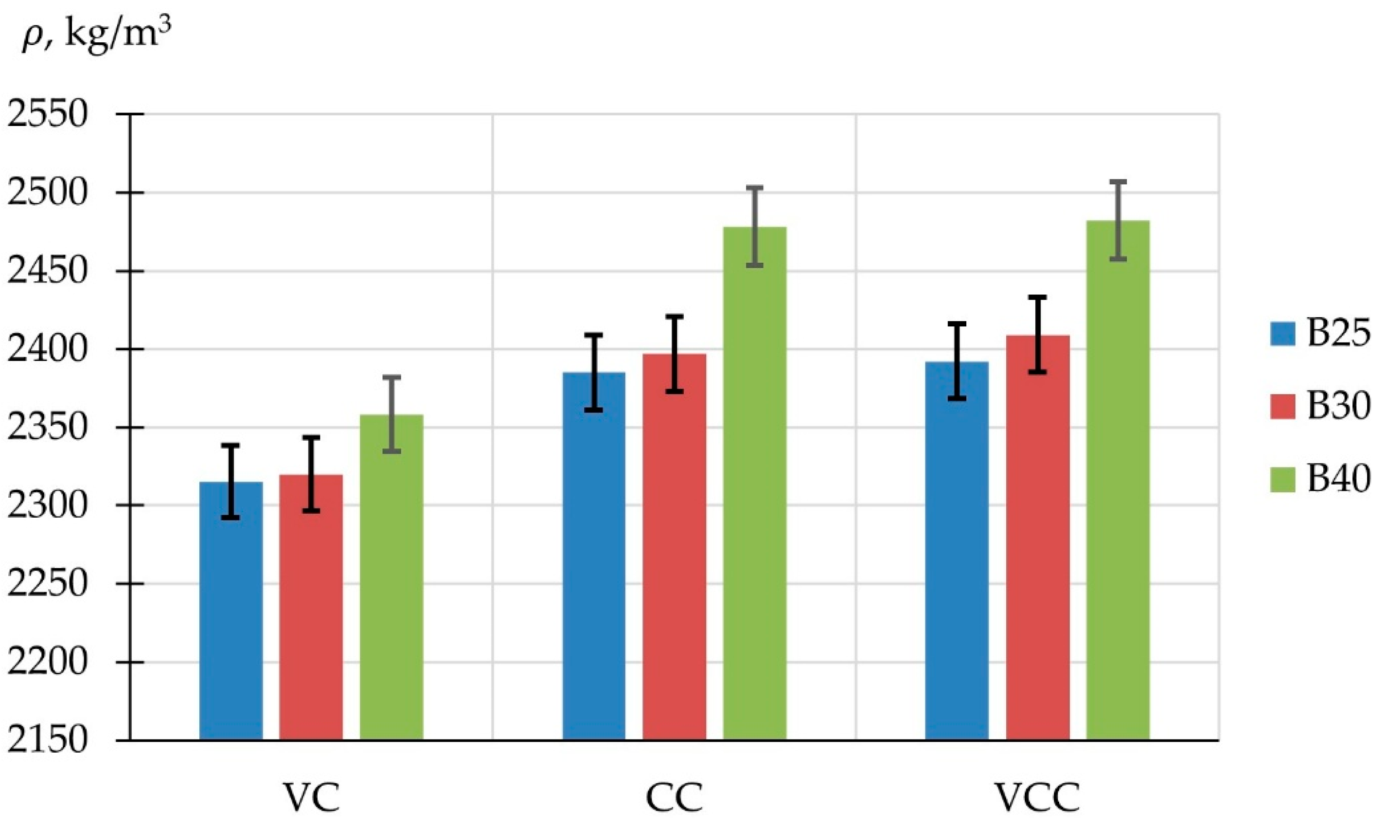
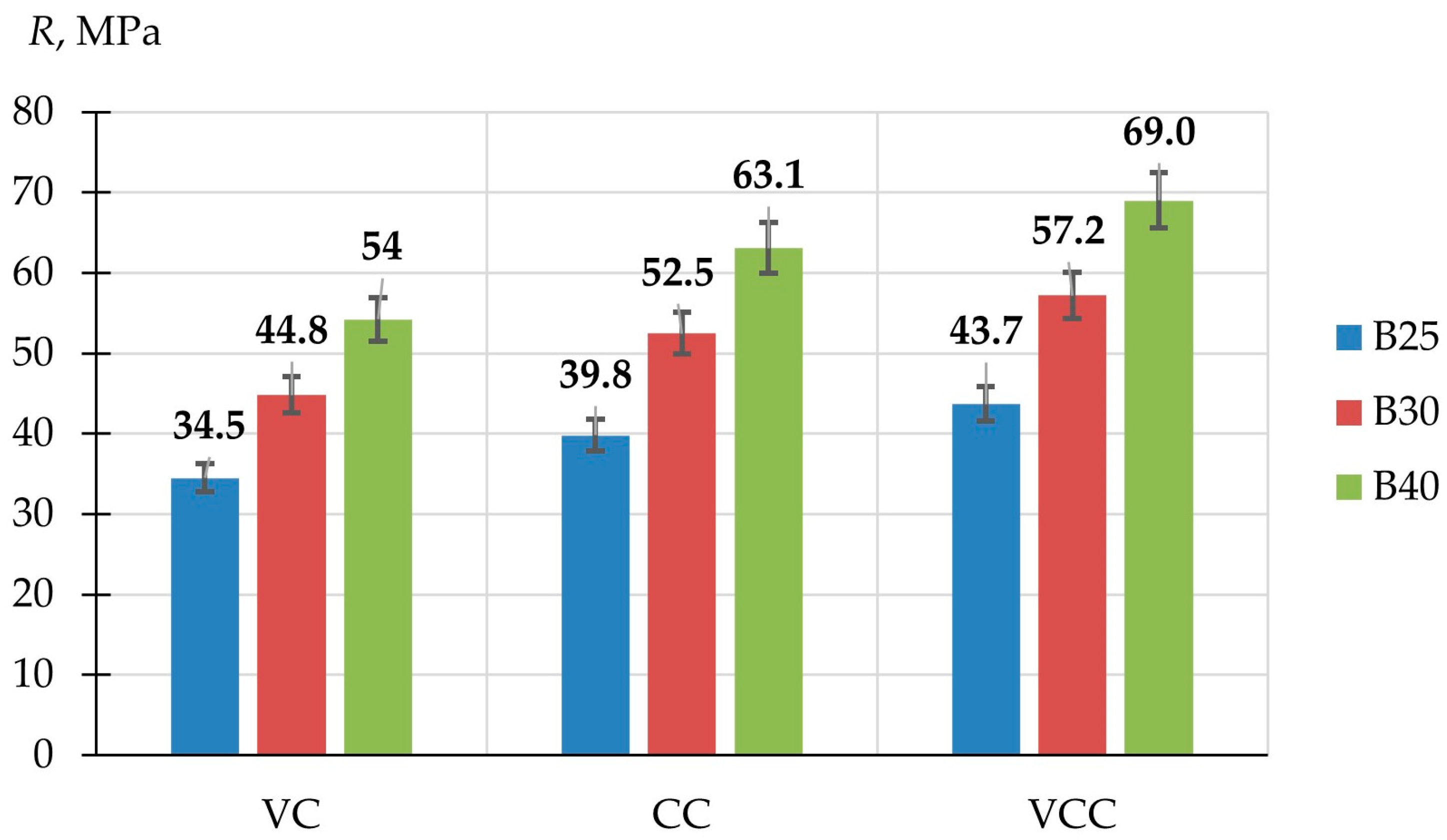
Figure 6, Figure 7, Figure 8 and Figure 9 present the density, compressive strength, axial compressive strength and elastic modulus of B25, B30 and B40 design-grade concretes produced using V, C, and VC technologies. Figure 6 shows the values of concrete density (ρ) of different grades by compressive strength.
The density of concrete of design grade B25 manufactured using three different technologies varies from 2315 kg/m3 to 2392 kg/m3. The density of concrete of grade B30 varies from 2320 kg/m3 to 2409 kg/m3. The density of concrete of grade B40 varies from 2358 kg/m3 to 2482 kg/m3. The density of centrifuged and vibrocentrifuged concrete is always slightly higher than the density of vibrated concrete, which is due to differences in the methods of calculating concrete mix recipes. Figure 7 shows the results of determining the compressive strength of concrete (R) of different grades manufactured using different technologies.
Figure 7 shows that the compressive strength of concrete produced using different technologies varies significantly. Vibrocentrifuged concrete has the highest compressive strength. For all three grades B25, B30 and B40, the compressive strength values were 43.7 MPa, 57.2 MPa and 67.5 MPa, respectively. The compressive strength of centrifuged concrete of grades B25, B30 and B40 was 39.8 MPa, 52.5 MPa and 63.1 MPa, respectively. The compressive strength of vibrated concrete of grades B25, B30 and B40 was 34.5 MPa, 44.8 MPa and 54.0 MPa. According to the results of determining compressive strength, it was found that concrete of all grades, manufactured using the VC technology, have the highest strengths in comparison with samples manufactured using the C and V technologies. The difference in the compressive strength values of concrete manufactured using different technologies is presented in Table 4.
A small increase in the density of centrifugally compacted concretes also leads to a certain increase in their compressive strength compared to vibrated concrete. This increase in strength is only part of the overall positive effect of centrifugal compaction on the properties of concrete and its structure, which consists of several factors, such as differences in the methods of calculating the formulations, in manufacturing technologies and in the structures that form.
Figure 8 shows the results of a comparison of the axial compressive strength (Rb) of concrete of different grades of compressive strength, manufactured using different technologies.
According to the results of determining the axial compressive strength (Figure 8), vibrocentrifuged concrete has the highest values for all the grades considered. The axial compressive strength of vibrocentrifuged concrete of grade B25 is 31.4 MPa, grade B30—42.3 MPa and grade B40—51.0 MPa. For centrifuged concrete of grades B25, B30 and B40, the axial compressive strength was 28.9 MPa, 38.7 MPa and 46.4 MPa, respectively. The axial compressive strength of vibrated concrete of similar grades was 25.1 MPa, 33.5 MPa and 39.9 MPa, respectively. The difference in the axial compressive strength values of concrete made using different technologies is presented in Table 5.
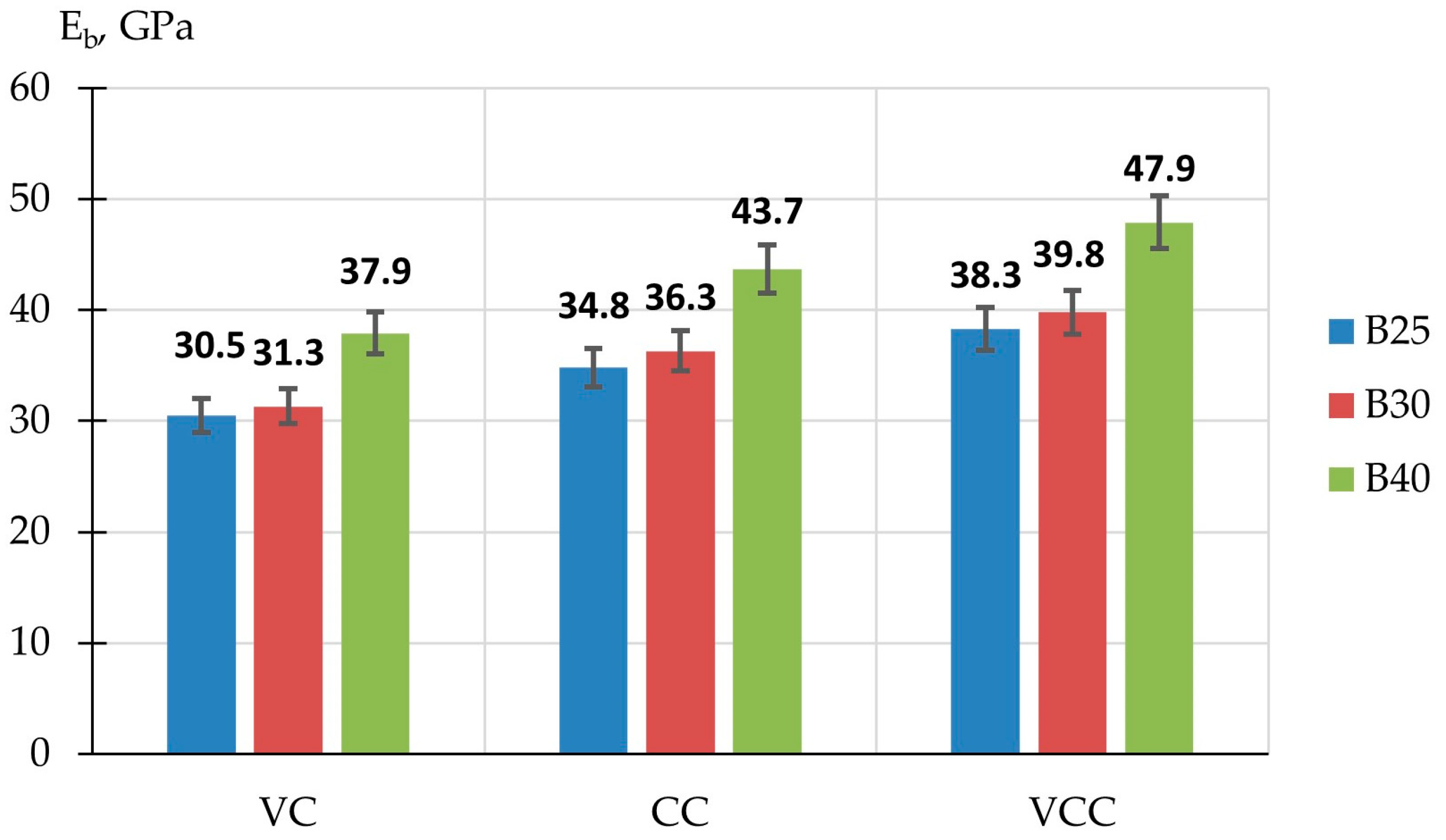
Figure 9 shows diagrams demonstrating the difference in the values of the modulus of elasticity (Eb) of concrete of different grades of compressive strength produced using different technologies.
Vibrocentrifuged concrete, as in the case of the results presented in Figure 8 and Figure 9, has the highest value of the modulus of elasticity. The values of the modulus of elasticity for vibrocentrifuged concrete of grades B25, B30 and B40 are 38.3 MPa, 39.8 MPa and 47.9 MPa, respectively. For centrifuged concrete of the same grades, the values of the modulus of elasticity are 34.8 MPa, 36.3 MPa and 43.7 MPa, respectively. For vibrated concrete, the modulus of elasticity is 30.5 MPa, 31.3 MPa and 37.9 MPa, respectively. The difference in the values of the elastic modulus of concrete produced using different technologies is presented in Table 6.
Based on the results of experimental studies of concrete grades B25, B30 and B40, manufactured using three different technologies, it was found that vibrocentrifuged concrete has higher strength properties compared to centrifuged and vibrated concrete. The results of determining the density, compressive strength, axial compressive strength and elastic modulus, shown in Figure 6, Figure 7, Figure 8 and Figure 9, prove the influence of the manufacturing technology on the final properties of the concrete composite. Concrete manufactured using the centrifugal compaction technology with additional vibration has the highest mechanical properties compared to concrete manufactured using centrifugal compaction or vibration. In general, the centrifugal compaction technology allows for the production of concrete with a special variatropic structure. Such concrete has a reinforced outer layer, since most of the crushed stone is concentrated in it. The middle layer in variable-density concrete is slightly inferior to the outer layer in terms of strength characteristics, due to the fact that it is mainly represented by cement-sand mortar with a small portion of coarse aggregate. The inner layer is the weakest and consists mainly of cement particles and water squeezed out of the outer layers. Due to such a heterogeneous structure, the concrete composite better resists destructive loads [62]. The heterogeneous structure of vibrocentrifuged concrete has a reinforced outer layer. This allows for the achievement of a high level of compression of the concrete core by the casing tube, which is impossible to achieve in vibrated concrete. This is also impossible to achieve on such a large scale in centrifuged concrete. That is, the main effect of improving the characteristics of the tube concrete column is to achieve a high degree of compression of the concrete core by the casing tube. The positive effect of centrifugal compaction on the properties of concrete and its structure has been proven in a number of previous studies [63,64,65,66,67,68,69]. Adding vibration (vibrocentrifugation) to centrifugal compaction leads to an even greater positive effect on the strength properties of concrete, which we have proven earlier in [47,70,71,72,73]. Thus, a further goal of the study is to study the mechanism of joint operation of steel shell tubes and a concrete core by experimentally determining the bearing capacity of tube concrete column samples manufactured using three different technologies.

3.2. FEM Analysis

The central compression task of a tube concrete column in which the concrete core is made using different technologies is considered. Taking into account the symmetry of the problem under consideration, the model for numerical analysis was constructed as a ¼ part of a solid column.
A four-layer column, in which the outer layer is a steel shell with a radius of R 0 = 51 mm and the three inner layers are vibrocentrifuged variatropic concrete, occupies a vertical position in space. The column axis 0 z h (where h = 1 m) coincides with the z axis, and the x and y axes are directed along the column radius. The lower surface of the column z = 0 is fixed in the z direction. The upper surface of the column z = 1 m is subject to displacement in the z direction by Δ h = 0 … 10 mm. The variatropic column has a hole in the middle with a radius of r 0 = 16 mm. The layers are rigidly coupled with each other, ensuring equality of the components of the displacement vectors of points lying on the boundary of the layers. The nodes lying in the plane of symmetry y = 0 ,   r 0 x R 0 are fixed in the direction Uy = 0. The nodes lying in the plane of symmetry x = 0 ,   r 0 y R 0 are fixed in the direction Ux = 0.
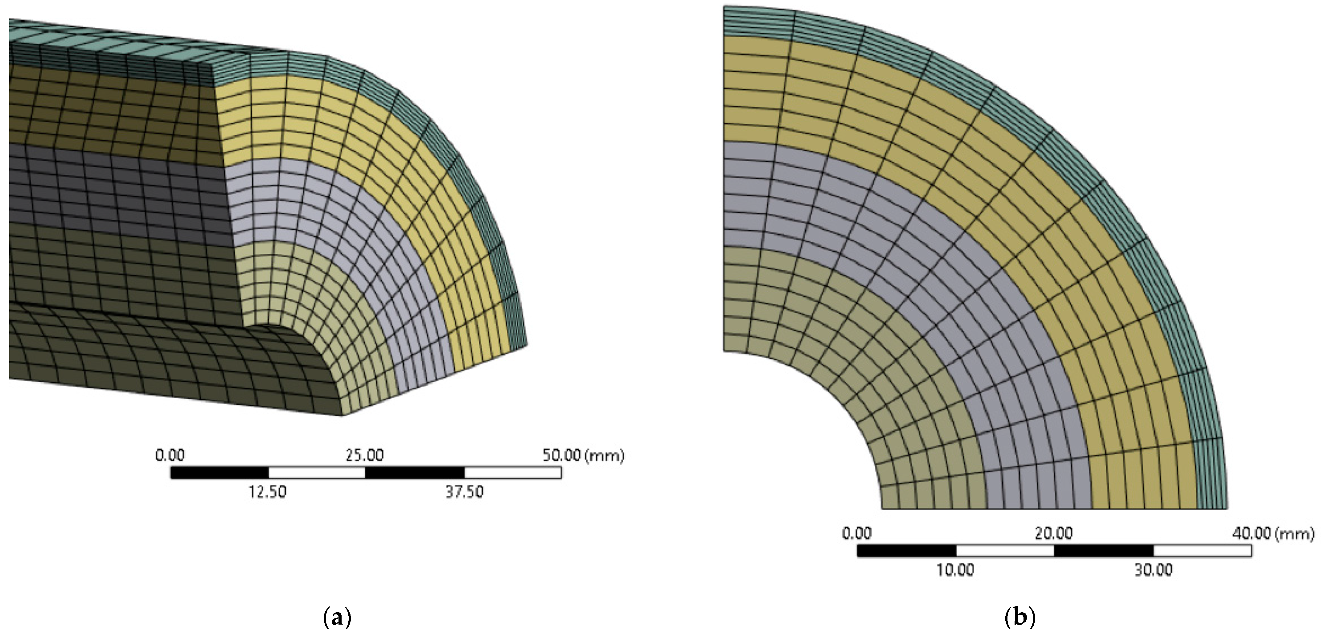
Finite element modeling was performed within the hypotheses of physical nonlinearity (Equations (5)–(9)) and geometrically linear elasticity theory under the assumption of small relative deformations of the model. In this case, the strain tensor e includes only linear components of the derivatives of displacements U. To construct the finite element mesh, an eight-node element with three degrees of freedom SOLID185 is used, which allows for the modeling of the plasticity of concrete and steel. Each of the three pipe layers was divided into six elements by thickness, shown in Figure 10, with a total of 235,789 nodes and 53,328 elements. The linear size of the element edges ranged from 0.5 mm to 7 mm. The verification of the cell size showed the convergence of the results at the current element size.
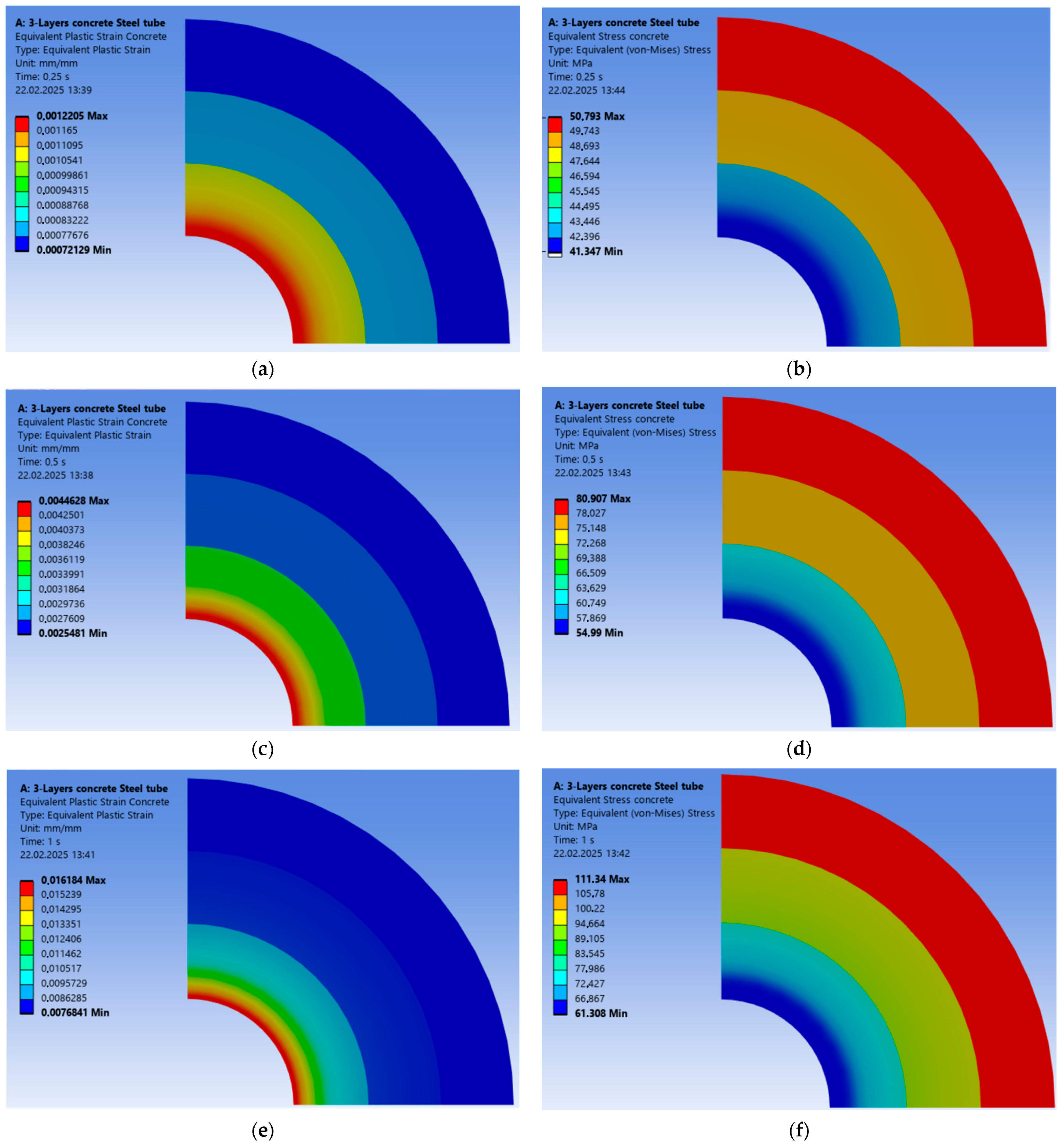
The sequential development of plastic deformation in concrete and equivalent von Mises stresses are shown in Figure 11a–f for different values of displacement Δ h = 2.5 mm, 5 mm and 10 mm.
Figure 11 shows that the development of equivalent plastic strain, and therefore the development of concrete failure, begins from the inner layer, which is the weakest of the three layers of the variable-strength structure. The middle and outer layers of variable-strength concrete are in a constrained stress–strain state, supported on one side by the steel shell, and on the other by the inner layer. Therefore, the bearing capacity of the column is largely determined by the strength and dimensions of the stronger layers of concrete, and the strength and thickness of the steel shell.

3.3. Bearing Capacity of Tube-Steel–Concrete Columns Manufactured Using Different Technologies

The main results of determining the actual N exp and calculated N F E M bearing capacity of centrally compressed tube-steel–concrete columns made of concrete of different grades manufactured using different technologies are presented in Figure 12, Figure 13 and Figure 14.
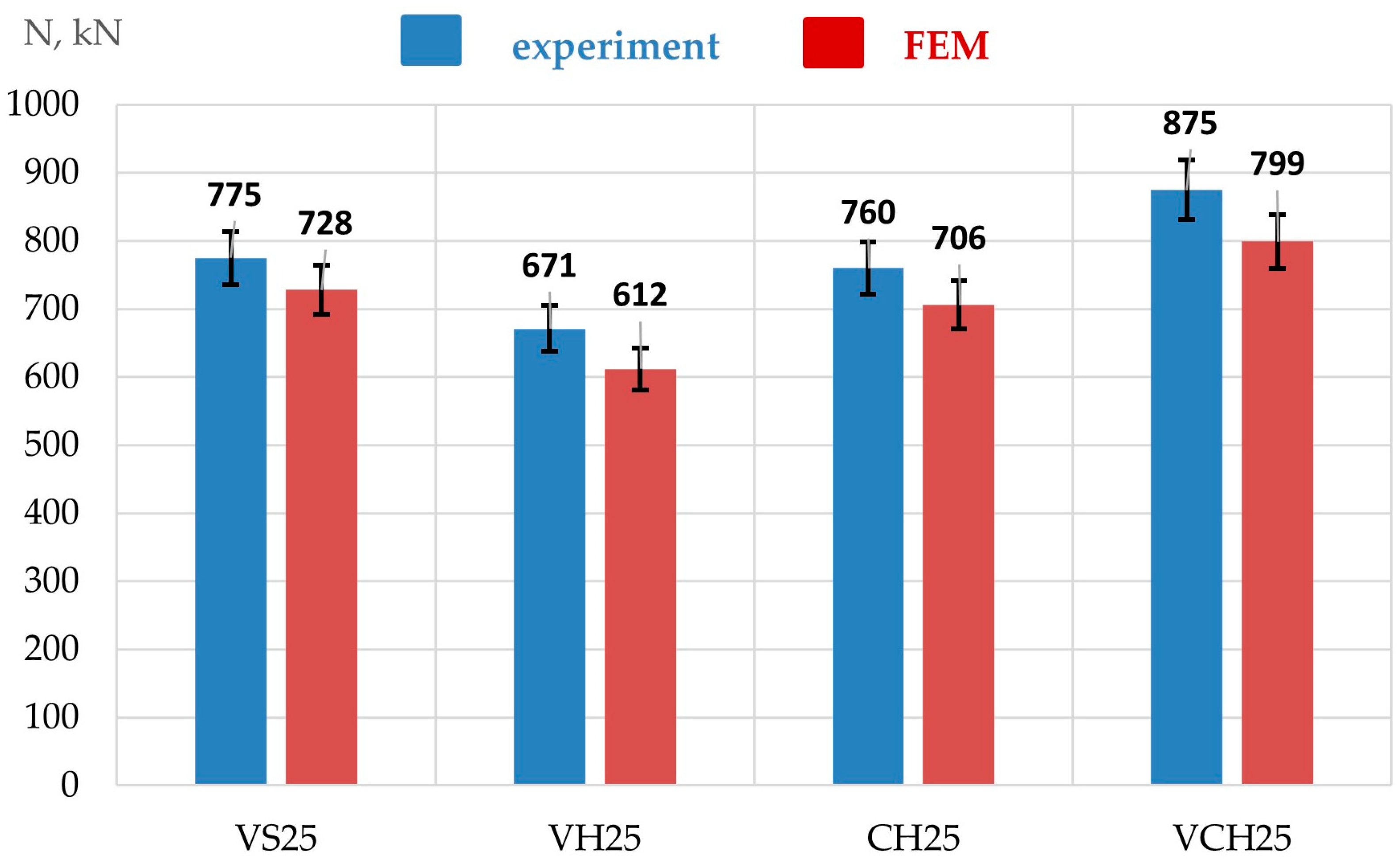
Figure 12 shows the graphical results of determining the actual and estimated bearing capacity of tube-steel concrete columns made of concrete of grade B25.
Based on the results of determining the actual bearing capacity of centrally compressed tube-steel concrete columns (Figure 12), the following was established. The solid tube-steel concrete column of type VS25 has a higher bearing capacity than the hollow tube-steel concrete column of type VH25, up to 13.4%. The hollow centrifuged tube-steel concrete column of type CH25 has a bearing capacity that is 13.3% higher than that of the VH25 column and 1.9% lower than that of the solid vibrated VS25. The hollow tube-steel concrete column manufactured using the VCH25 vibrocentrifugation technology has higher bearing capacity values than the tube-steel concrete column samples manufactured using vibration technology. Thus, in comparison with VS25, the bearing capacity of VCH25 was 12.9% higher, and in comparison with VH25, the bearing capacity was 30.4% higher. The heterogeneous structure of vibrocentrifuged concrete changes the nature of its stress–strain state. Unlike homogeneous concrete, vibrocentrifuged concrete begins to deteriorate from the inside, where the concrete zone is weakest. At the same time, the middle and outer layers, which are stronger than the inner ones, are in a constrained three-dimensional stress–strain state. The inner layer has the ability to deform inward, and the middle and outer layers are limited by a steel tube on one side and an inner layer on the other. It is these layers, together with the steel shell, that provide the greatest load-bearing capacity. Figure 13 shows the results of determining the actual and calculated bearing capacity of tube concrete columns made of B30 concrete.
From Figure 13, it is evident that the bearing capacity of a solid tube concrete column of type VS30, manufactured using vibration technology, is 12.6% higher than the bearing capacity of a vibrated hollow tube concrete column of type VH30. The centrifuged hollow tube concrete column of type CH30 has a bearing capacity higher than that of type VH30 by 12.0%. However, in comparison with a solid tube concrete column of type VS30, its bearing capacity is 2.1% lower. The hollow vibrocentrifuged tube concrete column of type VCH30 has the maximum bearing capacity. In comparison with VS30 and VH30 type tubular concrete columns, the bearing capacity of VCH30 was higher by 12.7% and 28.9%, respectively.
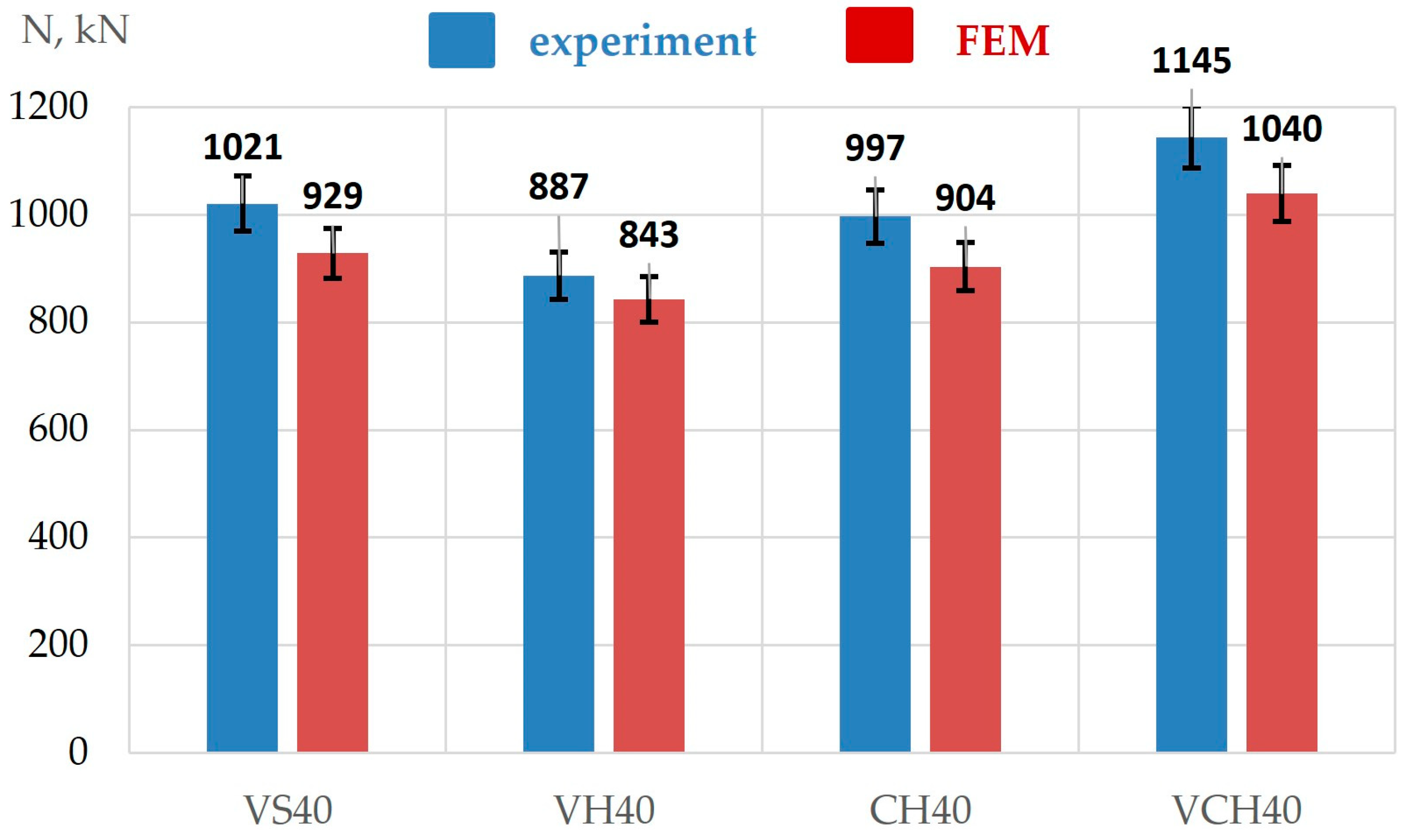
Figure 14 shows the results of determining the actual and calculated bearing capacity of tubular concrete columns made of B40 concrete.
As in the case of tube concrete columns in which concrete of grades B25 and B30 was used, the solid tube concrete column of type VS40 has a bearing capacity that is 13.1% higher than the hollow vibrated tube concrete column of type VH40. The hollow centrifuged tube concrete column of type CH40 has a bearing capacity value that is 12.4% higher than that of the tube concrete column of type VH40, and 2.4% lower than that of the solid vibrated VS40. The hollow vibrated centrifuged tube concrete column of type VCH40, in comparison with vibrated specimens of types VS40 and VH40, has bearing capacity values that are 12.1% and 29.1% higher, respectively.
The difference between the actual and calculated bearing capacity values is presented in Table 7.
According to the results of Table 7, the differences between the NFEM and Nexp calculation results were from 5.0% to 10.0% depending on the type of columns and the class of concrete they were made of. All calculated values of bearing capacity are less than the experimental values. No clear dependence on differences between the FEM results and the experimental results was revealed. The maximum difference of 10.0% was recorded for the vibrated solid concrete pipe column made of B30 concrete, and the minimum for the vibrated hollow concrete pipe column made of B40 concrete. There is a discrepancy between the experimental and calculated data, but in design calculation documents, such a discrepancy is acceptable and is controllable with the help of safety factors incorporated into the calculation methods.
As can be seen from the results of determining the bearing capacity of tube concrete columns (Figure 10, Figure 11 and Figure 12), hollow vibrocentrifuged tube concrete columns have the highest bearing capacity value in comparison with all other types of columns. The VC technology in the process of manufacturing a hollow tube concrete column allows for the formation of a concrete core of a unique variotropic structure. The variotropic structure of the concrete core is characterized by uneven concrete density throughout the entire cross-section of the product. For example, the outer layer of concrete in contact with the metal tube is the densest and contains most of the coarse aggregate, the middle layer is approximately comparable in density to the outer one, while the inner layer is inferior to both of them and is the least dense of all. Due to the high density of the outer and middle layers, the concrete composite has maximum strength, which is ultimately reflected in higher bearing capacity values of the columns. In comparison with vibrocentrifuged ones, centrifuged hollow tube concrete columns have a slightly different structure in the section of the outer and middle layers. The outer layer is denser than the middle one, and the crushed stone is not distributed between them as evenly as in the case of vibrocentrifuged concrete. Accordingly, due to this difference in the density of the layers, the strength of the centrifuged composite will be lower. In the case of vibrated columns, the structure of the concrete will be maximally non-uniform, and most of the crushed stone is concentrated in the lower part of the product, due to which the overall bearing capacity of the column will be the lowest in comparison with centrifuged and vibrocentrifuged columns.
Based on the results of experimental studies of pilot samples of tube concrete columns manufactured, the following dependencies were established:
-
the bearing capacity of solid and hollow tube concrete columns manufactured using V technology for concrete grades B25, B30 and B40 was always lower in comparison with tube concrete columns manufactured using VC technology;
-
hollow centrifuged tube concrete columns had a higher bearing capacity in comparison with hollow vibrated columns, which were higher by up to 13.3%. In comparison with solid vibrated columns, their bearing capacity was lower by up to 2.4%, respectively;
-
hollow vibrocentrifuged tube concrete columns in comparison with samples of vibrated solid tube concrete columns had a bearing capacity value higher than 12.9%, and, in comparison with samples of hollow vibrated columns, higher than 30.4%.
A new technology for producing hollow tube concrete columns was developed during this study. Experimental samples were subsequently manufactured and tested in compression. The results of testing experimental samples of tube concrete columns prove the efficiency of the proposed technology for producing tube concrete columns with their centrifugal compaction. The process of forming a concrete core in a tube concrete column during centrifugal compaction occurs as follows. When the metal tube rotates, the concrete mixture in it is distributed evenly and centrifugal pressure arises, under the influence of which particles of large aggregate converge and begin to move to the outer layer of the column. At the same time, centrifugal pressure acts on the liquid phase, and water with suspended fine fractions is squeezed out of the concrete mix and moves to the inner layer. The distribution of compressive stresses across the cross-sectional thickness of the finished product is non-uniform. They are higher at the outer wall of the column, and lower at the inner wall. Therefore, the liquid is squeezed out of the entire cross-sectional thickness unevenly; as a rule, most of it is squeezed out from the outer layer to the inner one. Due to this, the cohesion of the gel in the outer layers increases and better compaction of the concrete mix is achieved [69,74]. When horizontal-directed vibrations are added to centrifugation, the nature of the compaction of the concrete mix changes. Vibration promotes liquefaction of the concrete mix at the stage of its distribution along the metal tube, due to which the large aggregate is more evenly distributed in the middle and outer layers [75]. Part of the coarse aggregate grains, predominantly concentrated in the outer concrete layer adjacent to the metal tube, move to the middle layer as the mixture liquefies, and the difference between the outer and middle concrete layers of the tube concrete column decreases. Aligning the density of the structure of the middle and outer layers allows for the increase in the strength of the entire composite and the overall bearing capacity of the column. Centrifugal compaction of tube concrete elements allows the formation of a hollow concrete core with a variatropic structure. Tests of experimental samples of tube concrete columns prove that a concrete core with a variatropic structure works more effectively together with a metal shell. Centrifuged and vibrocentrifuged tube concrete columns have higher values of bearing capacity in comparison with samples of solid and hollow columns manufactured using vibration technology. The results of the study are in good agreement with the previous work [21], which proved that the strength of centrifuged concrete is 1.3–2.1 times higher relative to the same vibrated concrete, and the experimental value of the bearing capacity of hollow centrifuged tube concrete columns is 1.25 times higher than their theoretical bearing capacity.
It should be noted that the conducted research offers a new approach to the design solution of a tube-steel–concrete column due to the use of a hollow concrete core instead of a traditional solid one. Solid reinforced concrete structures are the classic and traditional option [76,77,78,79]. Using centrifugal compaction technology with directional vibration is a more effective approach in terms of economy, reduction in resource and labor intensity. There are known works on the creation of reinforced concrete elements by the centrifugal compaction method [56,71,80,81]. With this production method, the elements are hollow, having a ring cross-section. Thus, the weight of the structure is reduced, and due to the effect of centrifugal compaction, the resulting reinforced concrete products and structures achieve high quality. The production costs of vibrocentrifuged tube concrete columns will be lower than those of traditional solid columns due to the fact that the volume of concrete mixture used in production will be significantly smaller. Also, molding due to the physical effect of centrifugal compaction with vibration allows for the achievement of quality characteristics faster than vibrated columns. The production time of vibrocentrifuged columns is also reduced compared to vibrated ones, as it allows for more efficient use of formwork forms. According to preliminary general estimates of industrial partners, the overall efficiency of vibrocentrifuged columns compared to vibrated ones can reach 20%, including savings at the stages of transportation and installation. The spread of vibrocentrifugation technology to the reinforced concrete elements will achieve several advantages at once. First, the weight of the structure will be significantly reduced because of the production of a hollow concrete core. Second, the compression effect will be achieved not by additional technological methods, but by the physical effect of centrifugal compaction. The applied engineering advantages of such a solution are obvious. The key innovative aspect of using the vibrocentrifugation technology in the production of tube concrete columns is as follows. Without increasing the cost of the technology, by adding one element to the design of the process plant, it is possible to achieve a significant improvement in the quality of the concrete core in tube concrete columns. This approach will allow us to obtain a new type of tube concrete columns with a hollow concrete core, while ensuring high quality of the structures.
The efficiency of the new technology for the production of tube concrete columns by vibrocentrifugation has been confirmed by the results of experimental studies and has great potential because of the lack of knowledge. Currently, the authors’ team is conducting laboratory studies on the issues of dispersed reinforcement of the concrete core with various types of fiber with the selection of the optimal type of fiber and percentage of reinforcement.
It is worth noting that in real construction practice, the use of tube concrete products, including columns, is limited. The innovation proposed by this study will increase the popularity of tube concrete columns in real construction practice due to their lower weight, high stability, strength and ease of installation.

4. Conclusions

The properties of concrete produced using vibration, centrifugation and vibrocentrifugation technology were studied. A new method for producing tube concrete columns using the technology of centrifugal compaction of concrete mix—vibrocentrifugation—was developed. Experimental samples of tube concrete columns were manufactured, their bearing capacity was determined experimentally and the efficiency of work under load was estimated by comparing the actual and calculated values of bearing capacity. The following conclusions were made based on the obtained results.
(1)
Concrete of grades B25, B30 and B40, produced using the vibrocentrifugation technology, had the best strength properties. The compressive strength of centrifuged and vibrocentrifuged concrete of grades B25, B30 and B40 is on average 16.3% and 27.2% higher, respectively, than that of vibrated concrete. The axial compressive strength of centrifuged and vibrocentrifuged concrete is, on average, 15.7% and 26.4% higher, respectively, than that of vibrated concrete. The elastic modulus of centrifuged and vibrocentrifuged concrete is, on average, 15.1% and 26.4% higher, respectively, than that of vibrated concrete. Using centrifugal compaction technology ensures the formation of a pronounced heterogeneous structure in concrete samples of annular cross-section, where the outer layer is the densest and strongest because of the high content of coarse aggregate, the middle layer contains less coarse aggregate and a larger portion of cement-sand mortar, the inner layer is mainly represented by cement particles and water squeezed out of the outer layers, and is the least durable. This variatropic structure makes it possible to obtain composites with improved properties. When combining centrifugal compaction and vibration, the coarse aggregate is distributed most evenly between the middle and outer layers, due to which the effectiveness of the strength properties of concrete further increases.
(2)
A technology for manufacturing hollow tube concrete columns using the vibrocentrifugation method has been developed. Hollow vibrocentrifuged tube concrete columns have experimentally determined bearing capacity values of 875 kN for B25, which is 30.4% higher than the bearing capacity of a hollow vibrated tube concrete column, 1003 kN for B30 concrete, which is 28.9% higher, and 1145 kN for B40 concrete, which is 29.1% higher. The bearing capacity of centrifuged tube concrete columns is lower than that of solid vibrated columns by 1.9%, 2.1% and 2.4% for concrete grades B25, B30 and B40, respectively. The bearing capacity of vibrocentrifuged tube concrete columns is higher than that of solid vibrated tube concrete columns by 12.9%, 12.7% and 12.1% for concrete grades B25, B30 and B40, respectively.
(3)
All calculated values of the bearing capacity turned out to be less than the experimental values from 5.0% to 10.0%. There is a discrepancy between the experimental and calculated data, but in design calculation documents, such a discrepancy is acceptable and is controllable with the help of safety factors incorporated into the calculation methods.
(4)
The developed technology of vibrocentrifuging tube concrete products has several advantages. First, the weight of the structure is significantly reduced due to the production of a hollow concrete core. Second, the compression effect is achieved not by additional technological methods, but by the physical effect of centrifugal compaction.
(5)
The future direction of research is associated with the development of new types of vibrocentrifuged tube concrete columns with a hollow dispersion-reinforced concrete core and an expanded study of their deformation and strength properties.
(6)
The practical application of vibrocentrifuged tube concrete columns can be realized in the construction of civil and industrial buildings and structures, especially in areas with high seismic activity.

Author Contributions

Conceptualization, S.A.S., E.M.S., L.R.M. and N.S.; methodology, S.A.S., E.M.S. and D.E.; software, I.A.P.; validation, S.A.S., E.M.S., I.V. and A.C.; formal analysis, A.N.B., I.A.P. and A.L.M.; investigation, S.A.S., E.M.S., A.N.B., N.S., I.A.P., A.C. and D.E.; resources, S.A.S., E.M.S. and D.E.; data curation, S.A.S. and E.M.S.; writing—original draft preparation, S.A.S., E.M.S. and A.N.B.; writing—review and editing, S.A.S., E.M.S. and A.N.B.; visualization, I.V. and A.N.B.; supervision, A.N.B. and L.R.M.; project administration, A.N.B. and L.R.M.; funding acquisition, E.M.S. All authors have read and agreed to the published version of the manuscript.

Funding

The research was funded by the Russian Science Foundation, grant No. 23-79-10289, https://rscf.ru/en/project/23-79-10289/ (accessed on 16 March 2025).

Data Availability Statement

The original contributions presented in the study are included in the article, further inquiries can be directed to the corresponding author.

Acknowledgments

The authors would like to acknowledge the administration of Don State Technical University for their resources and financial support.

Conflicts of Interest

The authors declare no conflicts of interest.

References

  1. Al-Ezzi, M.J.; Ayamsir, A.; Supian, A.B.M.; Beddu, S.; Al-Dala’ien, R.N. Flexural Behavior and Failure Modes of Pultruded GFRP Tube Concrete-Filled Composite Beams: A Review of Experimental and Numerical Studies. Buildings 2024, 14, 3966. [Google Scholar] [CrossRef]
  2. Kvocak, V.; Kanishchev, R.; Platko, P.; Hodovanets, E.; Al Ali, M. Stability of Steel Columns with Concrete-Filled Thin-Walled Rectangular Profiles. Sustainability 2023, 15, 16217. [Google Scholar] [CrossRef]
  3. Gershberg, O.A. Technology of Concrete and Reinforced Concrete Products; Stroiizdat: Moscow, Russia, 1971; p. 360. [Google Scholar]
  4. Zhang, Z.; Yang, Z.; Li, H.; Yang, W. Performance Analysis of the Structures Using Glass-Fiber-Reinforced-Polymer-Produced Hollow Internal Molds. Buildings 2024, 14, 1319. [Google Scholar] [CrossRef]
  5. Wang, Z.; Zhou, J.; Peng, K. The Potential of Multi-Task Learning in CFDST Design: Load-Bearing Capacity Design with Three MTL Models. Materials 2024, 17, 1994. [Google Scholar] [CrossRef] [PubMed]
  6. Gaidzhurov, P.P.; Volodin, V.A. Strength Calculation of the Coupling of the Floor Slab and the Monolithic Reinforced Concrete Frame Column by the Finite Element Method. Adv. Eng. Res. 2022, 22, 306–314. [Google Scholar] [CrossRef]
  7. Akhverdov, I.N. Reinforced Concrete Pressure Centrifuged Tubes; Stroyizdat: Moscow, Russia, 1967; p. 164. [Google Scholar]
  8. Krishan, A.L.; Astafeva, M.A.; Rimshin, V.I.; Shubin, I.L.; Stupak, A.A. Compressed Reinforced Concrete Elements Bearing Capacity of Various Flexibility. Lect. Notes Civ. Eng. 2022, 182, 283–291. [Google Scholar] [CrossRef]
  9. Krishan, A.; Troshkina, E.; Rimshin, V. Experimental Research of the Strength of Compressed Concrete Filled Steel Tube Elements. Adv. Intell. Syst. Comput. 2020, 1116, 560–566. [Google Scholar] [CrossRef]
  10. More, F.M.D.S.; Subramanian, S.S. Experimental Investigation on the Axial Compressive Behaviour of Cold-Formed Steel-Concrete Composite Columns Infilled with Various Types of Fibre-Reinforced Concrete. Buildings 2023, 13, 151. [Google Scholar] [CrossRef]
  11. Zhang, X.; Niu, J.; Qiao, S.; Luo, C.; Fan, Y.; Kuang, X.; Huang, Y. Study on Eccentric Compression Mechanical Characteristics of Basalt Fiber-Reinforced Recycled Aggregate Concrete-Filled Circular Steel Tubular Column. Coatings 2023, 13, 1923. [Google Scholar] [CrossRef]
  12. Zhang, X.; Luo, C.; Wang, J.; Kuang, X.; Huang, Y. The Axial Compression Behavior of Basalt Fiber-Reinforced Recycled Aggregate Concrete-Filled Circular Steel-Tubular Column. Sustainability 2023, 15, 14351. [Google Scholar] [CrossRef]
  13. Xia, D.; Chang, W.; Li, B.; Gao, A.; Wu, F. Behaviour of steel-fibre-reinforced geopolymer concrete-filled square steel tubular stub column under axial compression. Structures 2024, 67, 107028. [Google Scholar] [CrossRef]
  14. Huang, Y.; Zhao, P.; Lu, Y.; Liu, Z. Hysteresis performance of steel fiber-reinforced high-strength concrete-filled steel tube columns. J. Constr. Steel Res. 2024, 219, 108755. [Google Scholar] [CrossRef]
  15. Mazhiev, K.N.; Mazhiev, K.K.; Panasenko, Y.V.; Mazhieva, A.K.; Mazhiev, A.K.; Mazhiev, A.K. Adhering to Regulatory Requirements in Calculation of Earthquake Resistance of the Structures of Life-Saving Buildings. Mod. Trends Constr. Urban Territ. Plan. 2024, 3, 17–29. [Google Scholar] [CrossRef]
  16. Bazhenov, Y.M.; Murtazaev, S.-A.; Bataev, D.-S.; Alaskhanov, A.H.; Murtazaeva, T.; Saydumov, M. High-strength concretes based on anthropogenic raw materials for earthquake resistant high-rise construction. Eng. Solid Mech. 2021, 9, 335–346. [Google Scholar] [CrossRef]
  17. Liu, B.; Zhang, L.; Feng, M.; Sun, H.; Chai, Y. Experimental Study of Rubber-Concrete-Filled CST Composite Column Under Axial Compression. Int. J. Steel Struct. 2022, 23, 247–262. [Google Scholar] [CrossRef]
  18. Wang, Y.-H.; Zeng, W.; Ayough, P.; Ren, W.; Wang, W.; Loganathan, L.; Yap, S.P. Axial compression performance of rubberized concrete-filled steel tubular stub columns after fire exposure: Experimental investigation and calculation models. Constr. Build. Mater. 2024, 438, 137129. [Google Scholar] [CrossRef]
  19. Su, R.; Li, X.; Zhong, T.; Zhou, T. Axial behavior of novel CFDST columns with outer welded corrugated steel tubes. Structures 2021, 34, 2708–2720. [Google Scholar] [CrossRef]
  20. Yang, L.; Wang, Y.; Elchalakani, M.; Fang, Y. Experimental behavior of concrete-filled corrugated steel tubular short columns under eccentric compression and non-uniform confinement. Eng. Struct. 2020, 220, 111009. [Google Scholar] [CrossRef]
  21. Šapalas, A.; Mudrov, A. Analysing the Confinement Effect in Hollow Core Steel-Concrete Composite Columns under Axial Compression. Materials 2021, 14, 6046. [Google Scholar] [CrossRef]
  22. Jing, C.; Zhao, L.; Wu, T.; Li, W. Experimental and Numerical Simulation of Reinforced Concrete-Filled Square GFRP Tubular Columns under Axial Compression. Materials 2024, 17, 2595. [Google Scholar] [CrossRef]
  23. Jiang, L.; Hong, Y.; Ji, J.; Liu, Y.; Zhang, Z.; Chu, X.; Ma, G. Bearing Behavior of Engineered Cementitious Composite and Ultra-High-Performance Concrete Filled-In Double Steel Tubular Composite Columns Subjected to Eccentrical Load. Buildings 2024, 14, 1487. [Google Scholar] [CrossRef]
  24. Liu, J.; Yu, W.; Fang, Y.; Pan, Z.; Cao, G. Finite Element Analysis on the Seismic Performance of Concrete-Filled Steel Tube Columns with a Multiple-Chamber Round-Ended Cross-Section. Buildings 2024, 14, 1154. [Google Scholar] [CrossRef]
  25. Wei, J.; Ying, H.; Yang, Y.; Zhang, W.; Bao, C. Experimental and numerical investigation of the seismic performance of concrete-filled steel tubular composite columns with UHPC plates. Structures 2023, 58, 10544. [Google Scholar] [CrossRef]
  26. Liao, J.; Asteris, P.G.; Cavaleri, L.; Mohammed, A.S.; Lemonis, M.E.; Tsoukalas, M.Z.; Skentou, A.D.; Maraveas, C.; Koopialipoor, M.; Armaghani, D.J. Novel Fuzzy-Based Optimization Approaches for the Prediction of Ultimate Axial Load of Circular Concrete-Filled Steel Tubes. Buildings 2021, 11, 629. [Google Scholar] [CrossRef]
  27. Chepurnenko, A.; Turina, V.; Akopyan, V. Artificial Neural Network Models for Determining the Load-Bearing Capacity of Eccentrically Compressed Short Concrete-Filled Steel Tubular Columns. CivilEng 2024, 5, 150–168. [Google Scholar] [CrossRef]
  28. Khan, K.; Biswas, R.; Gudainiyan, J.; Amin, M.N.; Qureshi, H.J.; Arab, A.M.A.; Iqbal, M. PCA-Based Hybrid Intelligence Models for Estimating the Ultimate Bearing Capacity of Axially Loaded Concrete-Filled Steel Tubes. Materials 2022, 15, 6477. [Google Scholar] [CrossRef]
  29. Le, T.T.; Chi Phan, H.; Duong, H.T.; Le, M.V. Optimal design of circular concrete-filled steel tubular columns based on a combination of artificial neural network, balancing composite motion algorithm and a large experimental database. Expert Syst. Appl. 2023, 223, 119940. [Google Scholar] [CrossRef]
  30. Faridmehr, I.; Nehdi, M.L.; Farokhi Nejad, A.; Sahraei, M.A.; Kamyab, H.R.; Kiyanets, A.V. An innovative multi-objective optimization approach for compact concrete-filled steel tubular (CFST) column design utilizing lightweight high-strength concrete. Int. J. Lightweight Mater. Manuf. 2024, 7, 405–425. [Google Scholar] [CrossRef]
  31. Hou, C.; Zhou, X.-G. Strength prediction of circular CFST columns through advanced machine learning methods. J. Build. Eng. 2022, 51, 104289. [Google Scholar] [CrossRef]
  32. Du, G.; Li, Z.; Song, G. A PVDF-Based Sensor for Internal Stress Monitoring of a Concrete-Filled Steel Tubular (CFST) Column Subject to Impact Loads. Sensors 2018, 18, 1682. [Google Scholar] [CrossRef]
  33. Zhang, T.; Wang, H.; Zheng, X.; Gao, S. Axial Compressive Behaviours of Coal Gangue Concrete-Filled Circular Steel Tubular Stub Columns after Chloride Salt Corrosion. Materials 2024, 17, 2782. [Google Scholar] [CrossRef] [PubMed]
  34. Wang, Y.; Hu, S. Experimental Investigation on the Response of Elliptical CFT Columns Subjected to Lateral Impact Loading. Buildings 2022, 12, 1847. [Google Scholar] [CrossRef]
  35. Tao, Z.; Hasan, M.M.; Han, D.; Qin, Q.; Abdul Ghafar, W. Study of the Axial Compressive Behaviour of Cross-Shaped CFST and ST Columns with Inner Changes. Buildings 2023, 13, 423. [Google Scholar] [CrossRef]
  36. Hasan, M.M.; Tao, Z.; Ghafar, W.A.; Huangfu, S.-E.; Zhang, Z. Investigating the axial compressive behavior of cruciform CFST columns: An experimental study. Structures 2024, 69, 107538. [Google Scholar] [CrossRef]
  37. Han, D.; Tao, Z.; Abdul Ghafar, W.; Hasan, M.M.; Xiao, W.; Wang, T.; Zhou, K.; Dai, H. Experimental Study on the Seismic Performance of L-Shaped CFST Columns in Different Combinations. Buildings 2023, 13, 2320. [Google Scholar] [CrossRef]
  38. Su, J.; Zhao, Q.; Cai, L.; Li, X.; Pu, H.; Dai, W.; Zhang, J.; Lu, D.; Liu, F. Feasibility of Recycled Aggregate Concrete in a Novel Anchoring Connection for Beam-to-Concrete-Filled Steel Tube Joints. Buildings 2024, 14, 1178. [Google Scholar] [CrossRef]
  39. Zheng, W.; Xu, B.; Xia, Z.; Wang, J.; Liu, J.; Yao, Y.; Wang, Y. A Concrete Core Void Imaging Approach and Parameter Analysis of Concrete-Filled Steel Tube Members Using Travel Time Tomography: Multi-Physics Simulations and Experimental Studies. Sensors 2024, 24, 2503. [Google Scholar] [CrossRef]
  40. Zhang, C.; Li, J.; Liu, Y.; Cheng, Q.; Sun, Z. Seismic Vulnerability Analysis of Concrete-Filled Steel Tube Structure under Main–Aftershock Earthquake Sequences. Buildings 2024, 14, 869. [Google Scholar] [CrossRef]
  41. Ovsyankin, V.I. Reinforced Concrete Tubes for Pressure Water Conduits; Stroyizdat: Moscow, Russia, 1971; p. 320. [Google Scholar]
  42. GOST 1577-2022; Rolled Sheets and Wide Strips of Structural Quality Steel. Specifications. Russian Institute of Standardization: Moscow, Russia, 2024. Available online: https://docs.cntd.ru/document/1300390693 (accessed on 10 February 2025).
  43. GOST R 70306-2022; Centrifugated Reinforced Concrete Posts of Annular Section for Industrial Buildings and Structures. Specifications. Russian Standardization Institute: Moscow, Russia, 2022. Available online: https://docs.cntd.ru/document/1200192844 (accessed on 14 March 2025).
  44. VSN 1-90; Fabrication Requirements for Centrifugal-Cast Support Pillars for Contact Lines, Communications Lines, and Lock-Out Systems. USSR Mintransstroy: Moscow, Russia, 1990. Available online: https://www.gostrf.com/normadata/1/4294851/4294851029.pdf (accessed on 3 February 2025).
  45. GOST 27006-2019; Concretes. Rules for Mix Proposing. Standartinform: Moscow, Russia, 2020. Available online: https://docs.cntd.ru/document/1200165762 (accessed on 3 February 2025).
  46. Stel’makh, S.A.; Kholodnyak, M.G.; Shcherban’, E.M.; Nazhuev, M.P.; Chernil’nik, A.A. Device for the Manufacture of Products from Centrifuged Concrete. Russian Federation Patent RU 192 492 U1, 23 May 2019. Available online: https://yandex.ru/patents/doc/RU192492U1_20190918 (accessed on 16 March 2025).
  47. Shcherban’, E.M.; Stel’makh, S.A.; Mailyan, L.R.; Beskopylny, A.N.; Smolyanichenko, A.S.; Chernil’nik, A.; Elshaeva, D.; Beskopylny, N. Influence of Polymer Fibers on the Structure and Properties of Modified Variatropic Vibrocentrifuged Concrete. Polymers 2024, 16, 642. [Google Scholar] [CrossRef]
  48. EN 12390-7:2019; Testing Hardened Concrete—Part 7: Density of Hardened Concrete. iTeh Standards: Etobicoke, ON, Canada, 2019. Available online: https://standards.iteh.ai/catalog/standards/cen/811a0cf3-55e3-495a-b06e-5c302d5f2806/en-12390-7-2019 (accessed on 3 February 2025).
  49. GOST 10180-2012; Concretes. Methods for Strength Determination Using Reference Specimens. Standartinform: Moscow, Russia, 2018. Available online: https://docs.cntd.ru/document/1200100908 (accessed on 3 February 2025).
  50. EN 12390-1:2021; Testing Hardened Concrete—Part 1: Shape, Dimensions and Other Requirements of Specimens and Moulds. iTeh Standards: Etobicoke, ON, Canada, 2021. Available online: https://standards.iteh.ai/catalog/standards/cen/d1c9ccee-2e5a-425e-a964-961da95d2f99/en-12390-1-2021 (accessed on 3 February 2025).
  51. EN 12390-2:2019; Testing Hardened Concrete—Part 2: Making and Curing Specimens for Strength Tests. iTeh Standards: Etobicoke, ON, Canada, 2019. Available online: https://standards.iteh.ai/catalog/standards/cen/ae7e6a86-1cbc-455e-8b2a-8964be9087f9/en-12390-2-2019 (accessed on 3 February 2025).
  52. EN 12390-3:2019; Testing Hardened Concrete—Part 3: Compressive Strength of Test Specimens. iTeh Standards: Etobicoke, ON, Canada, 2019. Available online: https://standards.iteh.ai/catalog/standards/cen/7eb738ef-44af-436c-ab8e-e6561571302c/en-12390-3-2019 (accessed on 3 February 2025).
  53. EN 12390-4:2019; Testing Hardened Concrete—Part 4: Compressive Strength—Specification for Testing Machines. iTeh Standards: Etobicoke, ON, Canada, 2019. Available online: https://standards.iteh.ai/catalog/standards/cen/10b1c613-819b-42d7-8f94-480cd37a666a/en-12390-4-2019 (accessed on 3 February 2025).
  54. GOST 24452-2023; Concretes. Methods for Determination of Prismatic Compressive Strength, Modulus of Elasticity and Poisson’s ratio. Standartinform: Moscow, Russia, 2024. Available online: https://docs.cntd.ru/document/1304463277 (accessed on 3 February 2025).
  55. Betz, P.; Curosu, V.; Loehnert, S.; Marx, S.; Curbach, M. Gradeification of Multiaxial Behaviour of Fine-Grained Concrete for the Calibration of a Microplane Plasticity Model. Buildings 2023, 13, 2704. [Google Scholar] [CrossRef]
  56. Nastri, E.; Todisco, P. Macromechanical Failure Criteria: Elasticity, Plasticity and Numerical Applications for the Non-Linear Masonry Modelling. Buildings 2022, 12, 1245. [Google Scholar] [CrossRef]
  57. Bilal, K.A.; Mahamid, M.; Hariri-Ardebili, M.A.; Tort, C.; Ford, T. Parameter Selection for Concrete Constitutive Models in Finite Element Analysis of Composite Columns. Buildings 2023, 13, 1759. [Google Scholar] [CrossRef]
  58. Luo, H.; Zhang, S.; Sun, M.; Gong, S.; Hu, C. Large-Deformation Modeling of Surface Instability and Ground Collapse during Tunnel Excavation by Material Point Method. Buildings 2024, 14, 2414. [Google Scholar] [CrossRef]
  59. Zhou, L.; Deng, Z.; Ren, J.; Zhu, Y. Structural Effects on Compressive Strength Enhancement of Cellular Concrete During the Split Hopkinson Pressure Bar Test. Materials 2025, 18, 552. [Google Scholar] [CrossRef]
  60. Peng, S.; Li, Z.; Cheng, H.; Xu, Y.; Zhang, T.; Cao, G. Mechanical Response Characteristics and Tangent Modulus Calculation Model of Expansive-Clay Unloading Stress Path. Buildings 2024, 14, 2497. [Google Scholar] [CrossRef]
  61. Telichko, V.; Slavcheva, G.; Levchenko, A. Finite elements procedure for modelling mechanichal behaviour of layered 3D printed concrete elements with experimental validation. J. Build. Rehabil. 2024, 9, 151. [Google Scholar] [CrossRef]
  62. Korolev, E.V.; Bazhenov, Y.M.; Smirnov, V.A. Building Materials of Variatropic Frame Structure; National Research Moscow State University of Civil Engineering: Moscow, Russia, 2011; p. 304. [Google Scholar]
  63. Kliukas, R.; Lukoševičienė, O.; Jaras, A.; Jonaitis, B. The Mechanical Properties of Centrifuged Concrete in Reinforced Concrete Structures. Appl. Sci. 2020, 10, 3570. [Google Scholar] [CrossRef]
  64. Kaufmann, J.; Hesselbarth, D. High performance composites in spun-cast elements. Cem. Concr. Compos. 2007, 29, 713–722. [Google Scholar] [CrossRef]
  65. Völgyi, I.; Farkas, G.; Nehme, S.G. Concrete strength tendency in the wall of cylindrical spun-cast concrete elements. Period. Polytech. Civ. Eng. 2010, 54, 23–30. [Google Scholar] [CrossRef]
  66. Kliukas, R.; Jaras, A.; Lukoševičienė, O. Reinforced Spun Concrete Poles—Case Study of Using Chemical Admixtures. Materials 2020, 13, 302. [Google Scholar] [CrossRef]
  67. Indriūnas, S.; Kliukas, R.; Juozapaitis, A. Behavioral Analysis of a Mast with a Combined Prestressed Stayed Columns System and Core of a Spun Concrete Circular Cross-Section. Buildings 2023, 13, 2175. [Google Scholar] [CrossRef]
  68. Kudzys, A.; Kliukas, R. Probability-based design of spun concrete beam-columns. J. Civ. Eng. Manag. 2010, 16, 451–461. [Google Scholar] [CrossRef]
  69. Feng, B.; Zhu, Y.-H.; Xie, F.; Chen, J.; Liu, C.-B. Experimental Investigation and Design of Hollow Section, Centrifugal Concrete-Filled GFRP Tube Columns. Buildings 2021, 11, 598. [Google Scholar] [CrossRef]
  70. Shcherban’, E.M.; Stel’makh, S.A.; Mailyan, L.R.; Beskopylny, A.N.; Smolyanichenko, A.S.; Chernil’nik, A.A.; Elshaeva, D.M.; Beskopylny, N.A. Structure and Properties of Variatropic Concrete Combined Modified with Nano- and Micro-silica. Constr. Mater. Prod. 2024, 7, 3. [Google Scholar] [CrossRef]
  71. Beskopylny, A.N.; Stel’makh, S.A.; Shcherban’, E.M.; Mailyan, L.R.; Meskhi, B.; Beskopylny, N.; El’shaeva, D. Influence of the Chemical Activation of Aggregates on the Properties of Lightweight Vibrocentrifuged Fiber-Reinforced Concrete. J. Compos. Sci. 2022, 6, 273. [Google Scholar] [CrossRef]
  72. Shcherban’, E.M.; Stel’makh, S.A.; Mailyan, L.R.; Beskopylny, A.N.; Mailyan, A.L.; Shcherban’, N.; Chernil’nik, A.; Elshaeva, D. Composition and Properties of Lightweight Concrete of Variatropic Structure Based on Combined Aggregate and Microsilica. Buildings 2025, 15, 346. [Google Scholar] [CrossRef]
  73. Mailyan, L.R.; Stel’makh, S.A.; Shcherban’, E.M.; Zherebtsov, Y.V.; Al-Tulaikhi, M.M. Researches of physicomechanical and design characteristics of vibrated, centrifuged and vibrocentrifuged concretes. Adv. Eng. Res. 2021, 21, 5–13. [Google Scholar] [CrossRef]
  74. Shcherban’, E.M.; Stel’makh, S.A.; Mailyan, L.R.; Beskopylny, A.N.; Smolyanichenko, A.S.; Chernil’nik, A.; Elshaeva, D.; Beskopylny, N. Analytical Review of the Current State of Technology, Structure Formation, and Properties of Variatropic Centrifugally Compacted Concrete. Materials 2024, 17, 1889. [Google Scholar] [CrossRef]
  75. Beskopylny, A.N.; Stel’makh, S.A.; Shcherban’, E.M.; Mailyan, L.R.; Meskhi, B.; Beskopylny, N.; El’shaeva, D.; Kotenko, M. The Investigation of Compacting Cement Systems for Studying the Fundamental Process of Cement Gel Formation. Gels 2022, 8, 530. [Google Scholar] [CrossRef]
  76. Wei, J.; Xie, Z.; Zhang, W.; Luo, X.; Yang, Y.; Chen, B. Experimental study on circular steel tube-confined reinforced UHPC columns under axial loading. Eng. Struct. 2021, 230, 111599. [Google Scholar] [CrossRef]
  77. Tokgoz, S. Tests on plain and steel fiber concrete-filled stainless steel tubular columns. J. Constr. Steel Res. 2015, 114, 129–135. [Google Scholar] [CrossRef]
  78. Zhao, B.; Xie, B.; Xu, Z.; Wang, F.; Gao, Y. Study on Fire Temperature Field in Small-Section Steel-Shell Concrete Immersed Tube Tunnel Structure Based on CFD-FEM Method. Materials 2025, 18, 187. [Google Scholar] [CrossRef] [PubMed]
  79. Kim, D.; Jeon, C.-H.; Park, K.-T. Cyclic Performance of Prefabricated Bridge Piers with Concrete-Filled Steel Tubes and Improved Bracing Connection Detail. Appl. Sci. 2024, 14, 11810. [Google Scholar] [CrossRef]
  80. Han, X.; Wei, D.; Wang, P.; Wang, M.; Du, Z.; Ling, Z. Microstructure characteristics and evolution of tube pile concrete under centrifugation and steam curing. Constr. Build. Mater. 2024, 450, 138554. [Google Scholar] [CrossRef]
  81. Stel’makh, S.A.; Shcherban’, E.M.; Beskopylny, A.N.; Mailyan, L.R.; Veremeenko, A.; Shilov, A.V.; Ananova, O.; Karalar, M.; Aksoylu, C.; Onuralp Özkılıç, Y. Modeling and Calculation of Improved Centrifuged Reinforced Concrete Columns with Variatropic Structure. Buildings 2023, 13, 2005. [Google Scholar] [CrossRef]
Figure 1. Granulometric composition: (a) CrS; (b) QS.
Buildings 15 00950 g001
Figure 2. Centrifugally compacted base concrete sample on a stone-cutting machine.
Buildings 15 00950 g002
Figure 3. Laboratory specimens after testing: (a) for compression (cube strength), (b) for axial compression (prism strength).
Buildings 15 00950 g003
Figure 4. Laboratory specimen of a ring-section tube concrete column: (a) front view, (b) top view of a solid specimen, (c) top view of a hollow specimen.
Buildings 15 00950 g004
Figure 5. Special laboratory installation for testing tube-steel concrete columns bearing capacity under axial load.
Buildings 15 00950 g005
Figure 6. Concrete density (ρ) of different compressive strength grades manufactured using different technologies (VC—vibrated, CC—centrifuged, VCC—vibrocentrifuged).
Buildings 15 00950 g006
Figure 7. Compressive strength of concrete (R) produced using different technologies (VC—vibrated concrete, CC—centrifuged concrete, VCC—vibrocentrifuged concrete).
Buildings 15 00950 g007
Figure 8. Axial compressive strength (Rb) of concrete of different compressive strength grades manufactured using different technologies (VC—vibrated, CC—centrifuged, VCC—vibro-centrifuged).
Buildings 15 00950 g008
Figure 9. Modulus of elasticity (Eb) of concrete of different compressive strength grades manufactured using different technologies (VC—vibrated, CC—centrifuged, VCC—vibrocentrifuged).
Buildings 15 00950 g009
Figure 10. Finite element model mesh: (a) side view; (b) top view.
Buildings 15 00950 g010
Figure 11. Sequential development of equivalent plastic strains (a,c,e) and equivalent von Mises stresses (b,d,f) in a variable-strength column (steel shell not shown).
Buildings 15 00950 g011
Figure 12. Results of determining the actual N exp and calculated N F E M bearing capacity of tube-steel–concrete columns with a B25 grade concrete core.
Buildings 15 00950 g012
Figure 13. Results of determining the actual N exp and calculated N F E M bearing capacity of tube-steel–concrete columns with a concrete core of grade B30.
Buildings 15 00950 g013
Figure 14. Results of determining the actual N exp and calculated N F E M bearing capacity of tube-steel–concrete columns with a concrete core of grade B40.
Buildings 15 00950 g014
Table 1. Physical and mechanical properties of the raw materials.
Raw MaterialIndicatorValue
PC Fineness of grinding (residue on the sieve No. 008) (%)3.9
Uniformity of volume change (expansion) (mm)0
Setting times (min)
- start
- end

115
220
Compressive strength at 2 (28) days (MPa)14.6 (50.1)
CrS Bulk density (kg/m3)1497
Density (kg/m3)2700
Resistance to fragmentation (wt %)10.6
The content of lamellar and acicular grains (wt %)6.6
QSBulk density (kg/m3)1400
Density (kg/m3)2600
Dust and clay particles (%)0.07
Clay in lumps (%)0
Organic and contaminant content (%)No
Table 2. Compositions of concrete mixtures.
Concrete GradeConcrete TypeConcrete Mixture Proportion Per 1 m3Slump (cm)Mixture Density (kg/m3)
PC (kg/m3)W (L/m3)CrS (kg/m3)QS (kg/m3)
B25VC32519510946903.52304
CC и VCC38019011396893.02386
B30VC35819210836733.02306
CC и VCC39219011286843.02399
B40VC43920010616403.52340
CC и VCC49220011096733.02474
VC—vibrated concrete; CC—centrifuged concrete; VCC—vibrocentrifuged concrete.
Table 3. Main characteristics of laboratory samples of tube concrete columns.
Sample MarkingConcrete GradeGeometrical Characteristics
Steel ShellConcrete Core
Outer Diameter (D), mmInner Diameter (d), mm Wall Thickness (t), mmOuter Diameter (D0), mmInner Diameter (d0), mm
VS25B2510296396
VH251029639632
CH251029639632
VCH251029639632
VS30B3010296396
VH301029639632
CH301029639632
VCH301029639632
VS40B4010296396
VH401029639632
CH401029639632
VCH401029639632
VS—vibrated solid tube concrete column; VH—vibrated hollow tube concrete column; CH—centrifuged hollow tube concrete column; VCH—vibrocentrifuged hollow tube concrete column.
Table 4. Difference in compressive strength values of concrete manufactured using different technologies.
∆R (%)B25B30B40
CC > VCVCC > VCVCC > CCCC > VCVCC > VCVCC > CCCC > VCVCC > VCVCC > CC
15.426.79.817.227.79.016.427.39.4
Table 5. Difference in the axial compressive strength values of concrete made using different technologies.
∆Rb (%)B25B30B40
CC > VCVCC > VCVCC > CCCC > VCVCC > VCVCC > CCCC > VCVCC > VCVCC > CC
15.125.18.715.526.39.316.327.89.9
Table 6. The difference in the values of the elastic modulus of concrete produced using different technologies.
∆Eb (%)B25B30B40
CC > VCVCC > VCVCC > CCCC > VCVCC > VCVCC > CCCC > VCVCC > VCVCC > CC
14.125.610.116.027.29.615.326.49.6
Table 7. The difference (∆N) in the values of actual (Nexp) and calculated (NFEM) bearing capacity.
N (%)B25B30B40
VSVHCHVCHVSVHCHVCHVSVHCHVCH
6.18.87.18.710.09.58.09.19.05.09.39.2
Disclaimer/Publisher’s Note: The statements, opinions and data contained in all publications are solely those of the individual author(s) and contributor(s) and not of MDPI and/or the editor(s). MDPI and/or the editor(s) disclaim responsibility for any injury to people or property resulting from any ideas, methods, instructions or products referred to in the content.