1. Introduction
Owing to construction material deterioration and increased design load, particular buildings may become operationally outdated or no longer meet current requirements, which raises several risks. Risks of shear damage during disasters can occur in certain structural components due to long-term deterioration and under-designed reinforced shear. It goes without saying that replacing every one of these structures would be impossible in terms of money and time. Frequently, the best workable method is to strengthen and repair buildings [
1]. One of the main areas of inquiry in structural engineering nowadays is the strengthening and reinforcing of concrete structures, with the goal of ensuring that older buildings can withstand the demands of modern use. Optimizing shear strengthening techniques in construction project management enhances efficiency, reduces costs, and ensures the durability of RC structures, ultimately maximizing the value for money while minimizing material waste and labor inefficiencies.
Strain Hardening Cementitious Composites (SHCC) are unique cementitious matrix components that exhibit excellent ductility, strength increase during cracking, and re-peated controlled-opening crack development [
2,
3]. Owing to its exceptional performance characteristics, SHCC has emerged as a potentially useful construction material for a broad range of engineering uses, including bridge decks [
4,
5,
6], turbines [
7], seismically-loaded constructions [
8,
9] and enhancing resistance to impact loads [
10,
11].
These days, repairing existing concrete structures is a viable use for SHCC. In this regard, multiple studies on the benefits of utilizing SHCC as a substrate for restoration have been conducted. The effectiveness of using sprayed SHCC for retaining wall rehabilitation in Gifu, Japan, was assessed by Rokugo et al. [
12]. They demonstrated that even 24 months after the repair, SHCC greatly lowers the crack opening on the wall surface. In order to restore the flexural integrity of concrete beams that had considerable steel corrosion, Chen et al. [
13] employed SHCC. They demonstrated how the corroded steel rebar’s load-carrying ability may be totally restored by SHCC patching. It has been demonstrated by Lim and Li [
14] that SHCC overlay methods create a unique crack capturing mechanism that can stop restoration pieces from spalling and delaminating. According to Kamada and Li’s [
15] research, the fracture behavior of the repair methods can be impacted by the surface cleaning of the beams. Martinola et al. [
16] evaluated the impact of using steel fiber reinforced concrete with tensile hardening characteristics for the strengthening and repair of RC beams. Kamal et al. [
17] evaluated the crack-opening effectiveness of a repair compound with strain-hardening characteristics. Flexural tests were conducted on repaired beams, where a specific location exhibited zero moment and tension. The authors demonstrated how the SHCC layer’s cracks gathered close to the substrate beam’s pre-existing cracks, which might lead to the repair layer failing locally. Hussein et al. [
18] discovered that employing SHCC strengthened with steel rebar can postpone the development of cracks in the strengthening layer.
According to studies by Patel et al. [
19], the ultimate torsional moment and rotations of RC beams were significantly increased when stainless steel wire reinforced with epoxy resin was applied to the concrete face. The shear efficiency of intact RC beams reinforced with textile-reinforced mortar (TRM) was compared to pre-damaged RC beams by Liying Guo et al. [
20]. The findings demonstrated a significant improvement in the shear strength of both the pre-damaged and intact RC beams reinforced by utilizing TRM. Peng et al.’s study [
21] examined the flexural behavior of reinforced concrete beams (RC beams) using both experimental and theoretical methods. The test findings showed that RC beams with decreasing capacity may be strengthened and repaired using cement grouting, which can also successfully restore or increase the RC beams’ load bearing capability. There is a dearth of studies currently available examining the refit of RC beams with composite components to prevent shear failure. A novel kind of strengthening innovation created during the current inquiry is a steel mesh fabric mortar strengthening system. The benefits of this strengthening technique include excellent concrete–polymer mortar bonding, good lengthening, ease of construction, high material strength, good overall durability, strong resistance to fire, and good chemical resistance. A lot of studies have been conducted on the behavior of RC beams [
22,
23,
24,
25,
26,
27,
28,
29,
30,
31,
32,
33]. Many studies have also been conducted on pre-cracked concrete elements [
27,
34,
35].
The present research suggests reinforcing RC beams that have shear defects by utilizing steel mesh fabric within high-performance mortar, such as strain-hardening cementitious composites, to make the sheared sections become integrated and work in tan-dem with the primary beam. This method of strengthening can be used on both damaged and non-damaged beams. Different numbers of layers of steel mesh fabric (single, double and triple) can be applied. In addition to a U-shaped structure, strengthening layers were applied to the beam’s sides. The shear strength of the strengthened beams was determined through analytical modeling by implementing a correction factor to take into consideration the debonding action between the SHCC layer and the beam sides.
3. Results and Analysis
3.1. Failure Modes
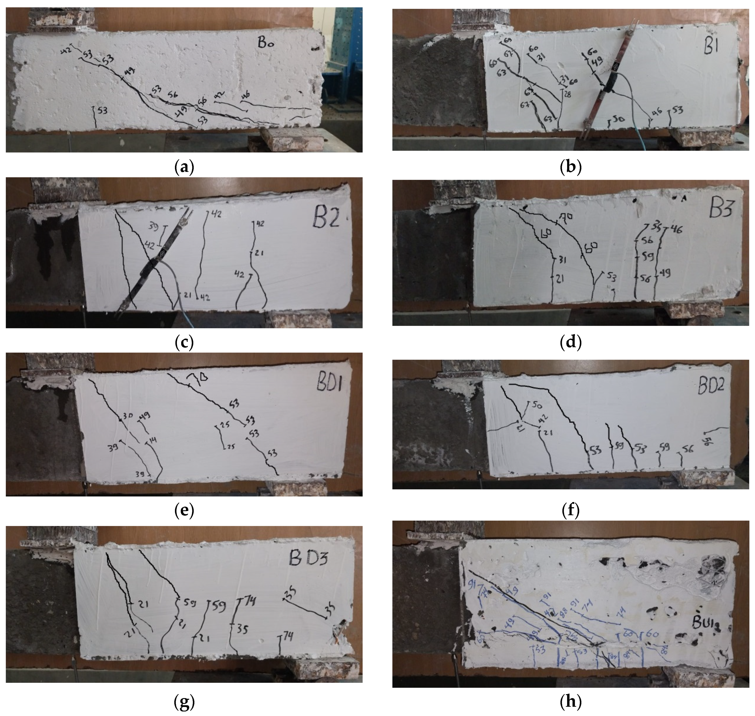
All tested beam breakdowns are displayed in
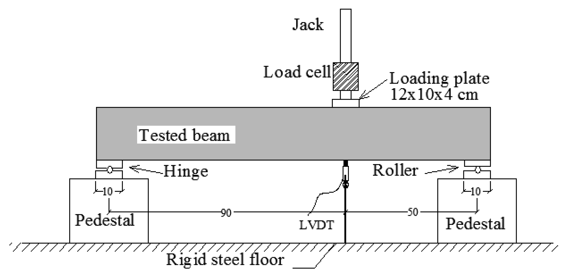
Figure 7. An illustration of the enhanced right shear span is presented. As intended, the strengthening was applied at the right shear span, where shear collapse caused all of the beams to fail. This happened as a result of the left shear span’s comparatively high shear stirrups and tension main bars. Since the shear span (a) and depth (d) of the beams that are being shown are 500 mm and 170 mm, respectively, a/d is 2.9. When a/d is more than 2.5, shear collapse is recognized as diagonal tension shear failure. Moreover, diagonal tension shear failure, which is caused by inadequate shear reinforcement, is the most dangerous type of shear failure. Moreover, collapse is caused by a diagonal shear fracture that begins at a 45-degree angle in the center of the beam’s height and expands swiftly. The choice to have this shear failure in the displayed beams was made in light of these considerations. It has long been understood that if a strengthening method applies to a lot of severe shear damage circumstances, it will be effective in the other cases as well, although the reverse need not be correct.
In control beam B0, as soon as the first shear crack appeared, the beam collapsed quickly, as this crack extended from the support to the loading point, the width of the crack opened quickly, and the load of the beam fell immediately after the first crack. In other words, due to the absence of internal shear reinforcement, once the first shear crack occurred, the failure happened in control unstrengthened beam B0. On the other hand, SHCC layers that were externally linked restricted shear cracking and prevented it from opening. SHCC layers may prevent the crack from propagating once it has begun, hence delaying shear failure and significantly increasing the final load. Because moments were present in the strengthening area, bending fractures developed in the strengthening layers; however, these cracks did not induce collapse and instead, the beams failed in shear. The morphology of the fractures was positively impacted by the strengthening techniques. In reinforced beams, the primary diagonal crack changed from one to many cracks. The strengthening layers increased the beam section at critical regions of the shear cut in the path of the crack and divided it, which improved the shear behavior. Moreover, internal reinforcement with a SHCC layer prevented rupture in the layers, hence the shear failure was delayed and the load capacity was increased.
As the load rose, closely spaced numerous damaged areas were found in the beams reinforced with SHCC coatings. A little amount of separation between the RC and SHCC was discovered close to the load point when the load approached its maximum capacity. At ultimate failure, extensive shear cracks were seen on the RC portion but no spalling or falling of debris were noticed as they were blocked by the SHCC layers. The system was able to retain integrity despite the extremely tiny cracks on the SHCC, which did not completely explode. Although the debonding happened gradually, the SHCC remained attached to the concrete foundation. Implementing these layers with a large thickness of up to 30 mm on both sides of the beam, which is equivalent to 50% of the beam width, significantly improved the behavior of the beams. Also, the use of fabric reinforcement within these layers prevented cuts from occurring after cracking occurred and allowed the layers to continue to perform their work for a long time.
All of these reasons allowed the four previously damaged beams (BD1, BD2, BD3 and BDU1) to regain their strength and work as efficiently as their counterparts (B1, B2 and B3) that had not been damaged before. It also turns out that the number of layers of internal reinforcement (SMFs) of SHCC does not greatly affect the cracking shape of the beams, either the damaged or undamaged ones. At maximum loads, partial separation of the strengthening layers appeared in some beams. This type did not occur in the beam BDU1 because the layers surrounded the sides and bottom of the beam together. The lower part of the layer helped increase the cohesion of the layers on both sides of the beam and prevented it from separating under high loading.
3.2. Load-Displacement Curves
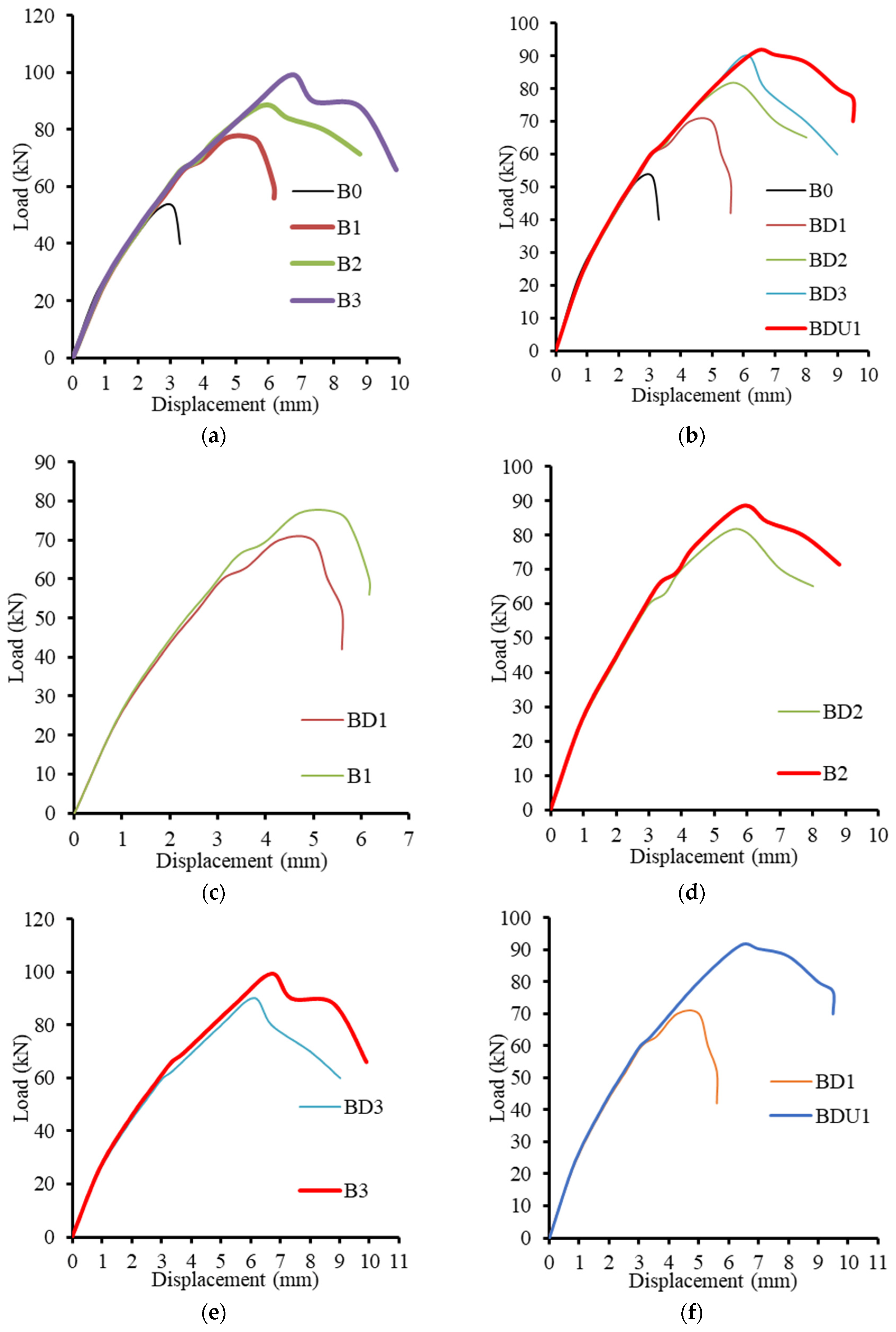
The applied load against the displacement beneath the loading point is shown in
Figure 8. Up to the cracking commencement, the first linear response of all tested beams was comparable. A somewhat different nonlinear response up to the peak load followed this. Because there were no internal shear stirrups, the control beam (B0) showed a sharp de-cline once it reached its shear capacity. However, the shear strength of the reinforced beams was improved by the SHCC layers. Moreover, as the number of SMFs increased, the tested beam’s shear capacity increased. Within the concrete matrix, the presence of SHCC layers aided in fracture distribution and management. SHCC layers can stop fractures from spreading quickly. The overall strength and integrity of the beam under shear stress were enhanced by the SHCC layers. Since the fibers connecting the structure can bear a considerable amount of tensile stress, the SHCC’s total strength was significantly higher. The rising mismatch in SHCC caused the construction material to react differentially to loading and to eventually separate, particularly at the loading point where the most deformation occurred. The specimen failed at its maximum load capacity due to debonding at certain spots, making it impossible for the SHCC to continue working with the substrate concrete to support further loads. Thus, SHCC’s true potential was not attained. Moreover, greater fiber rupture may result from the shear stress that is transported across a fracture as a result of crack shear sliding, which is mostly carried by the fiber bridging action. The next sections address the structural behavior in terms of ultimate displacement, ultimate shear capacity, and energy absorption capacity.
3.3. Ultimate Load
3.3.1. Effect of SMF Amount
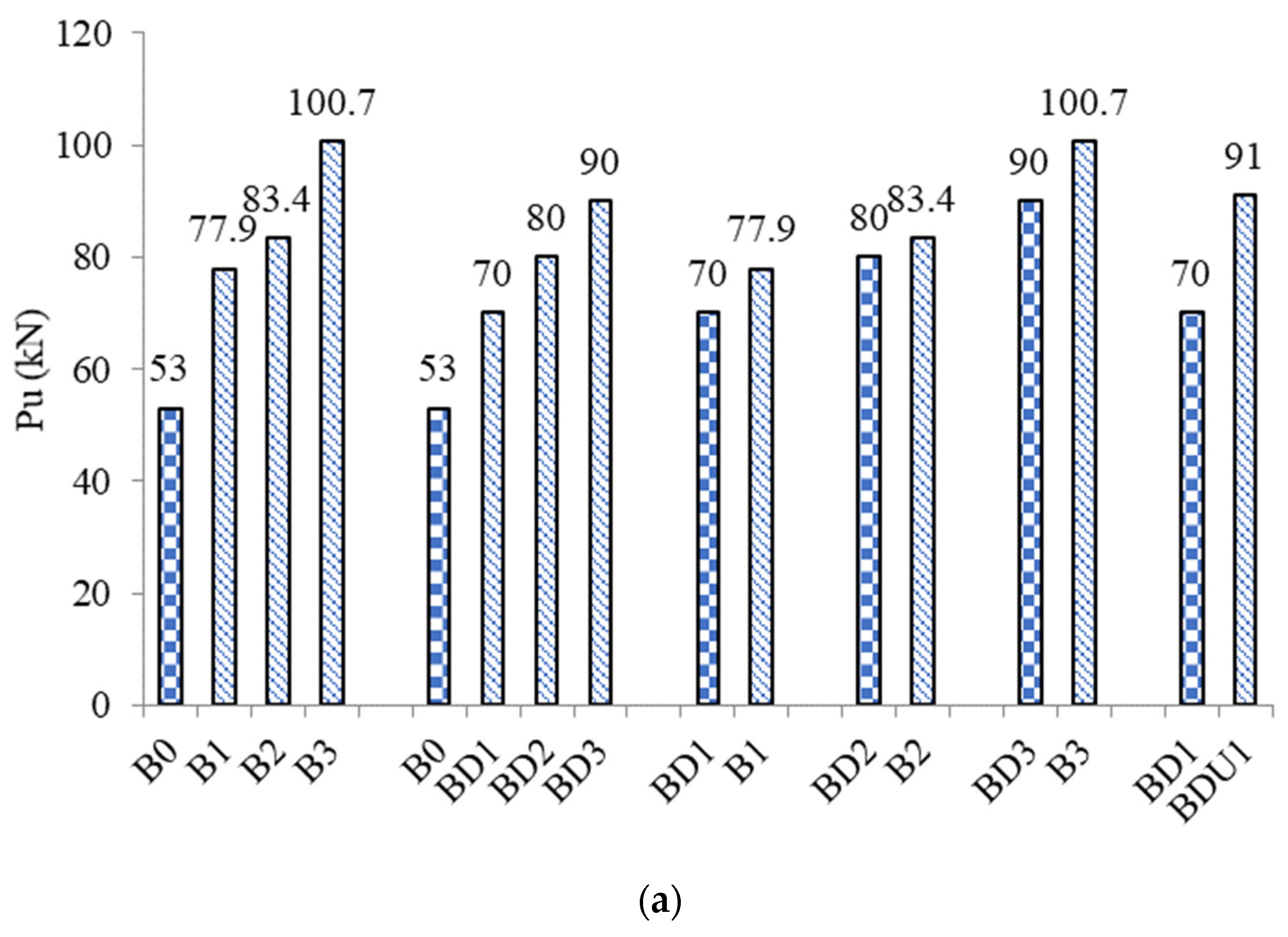
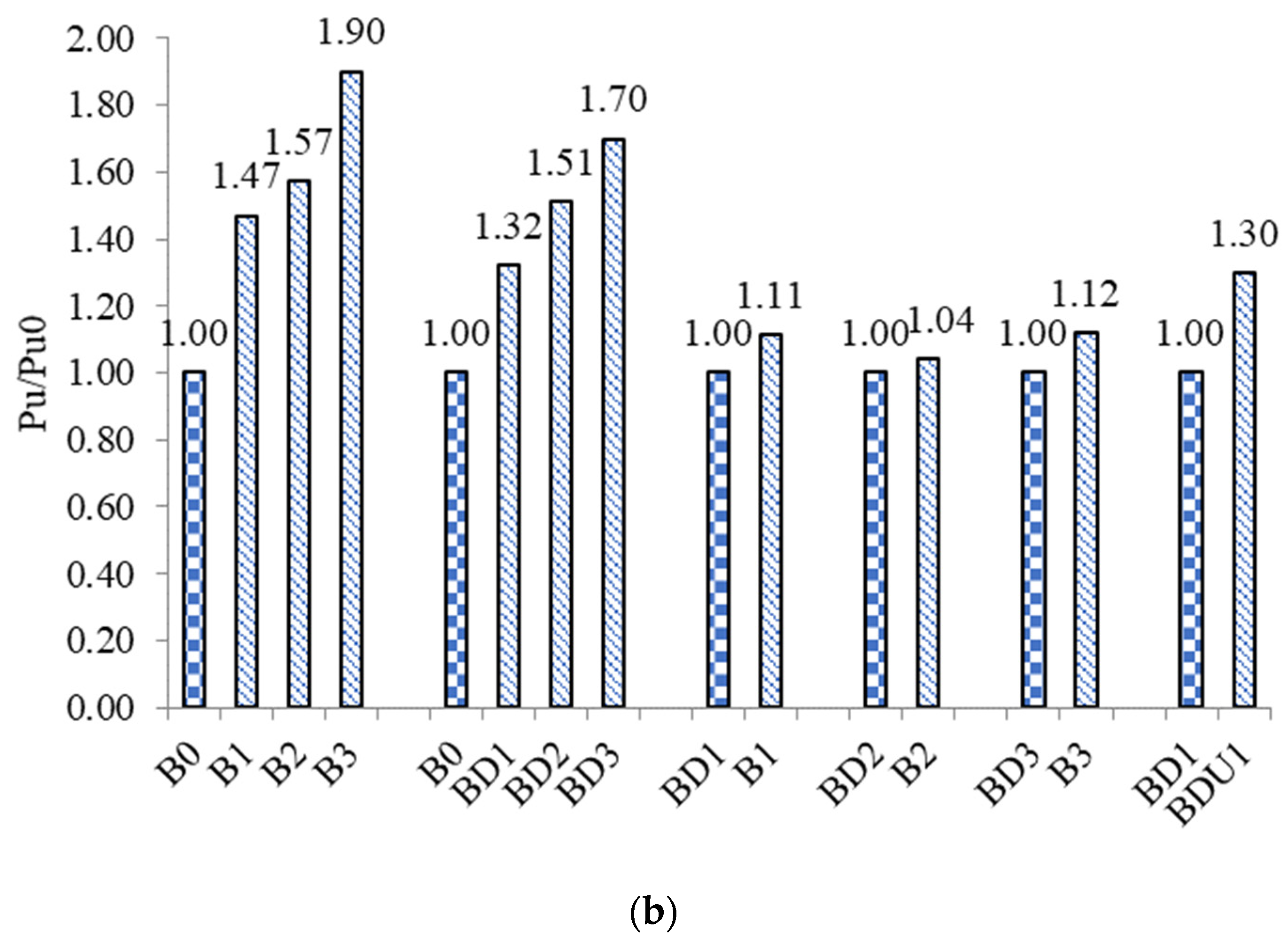
Groups A and B aimed to study the effect of steel mesh fabric (SMF) layers on the shear capacity of the undamaged and damaged beams, respectively. As shown in
Figure 9a, as the number of SMFs increased, the capacity of the beams improved more. The ultimate load (Pu) of strengthened beams B1, B2 and B3 was 77.9 kN, 83.4 kN and 100.7 kN, respectively, while the Pu of the unstrengthened beam B0 was 53 kN. As shown in
Figure 9b, the increase in the ratios of the Pu compared to control beam B0 reached 47, 57 and 90%, respectively, when one, two and three layers of SMF were applied. The reason for this is that the greater the number of layers of SMF, the greater the strength of the layer on the sides of the beam to withstand the tensile force generated as a result of the shear force. The greater the tensile strength of the layer, the more it can withstand, the more diagonal shear cracking is delayed, the crack is prevented from opening, and collapse is delayed, which leads to an increase in the maximum load of the strengthened beams B1, B2 and B3. The mesh reinforcement is also characterized by the small distance between its branches, which makes it difficult for the crack to pass through unless the filaments are cut. Also, the branches of the network extend in both directions and are connected together at intersections. These results are in line with those of earlier research [
37]. Tests using four-point loads were performed on RC slabs. Six RC slabs were strengthened with SHCC layers reinforced with steel rods, while one unstrengthened slab served as the control specimen. The thicknesses and reinforcement ratios of the SHCC layers varied. The findings showed that, in comparison to an unstrengthened slab, the suggested strengthening approaches considerably raised the ultimate failure load and the ductility index by up to 25% and 22%, respectively.
Group B is composed of the beams BD1, BD2 and BD3 that were strengthened after a damaging process. These beams were previously loaded until the first shear crack occurred at load 46 kN, which is close to the maximum load of the reference beam B0. This means that these beams were completely destroyed before the strengthening process was carried out. The results of group B proved that it is possible to restore the efficiency of previously damaged beams BD1, BD2 and BD3. When the beams BD1, BD2 and BD3 were strengthened, the maximum load improved significantly compared to the reference B0. As shown in
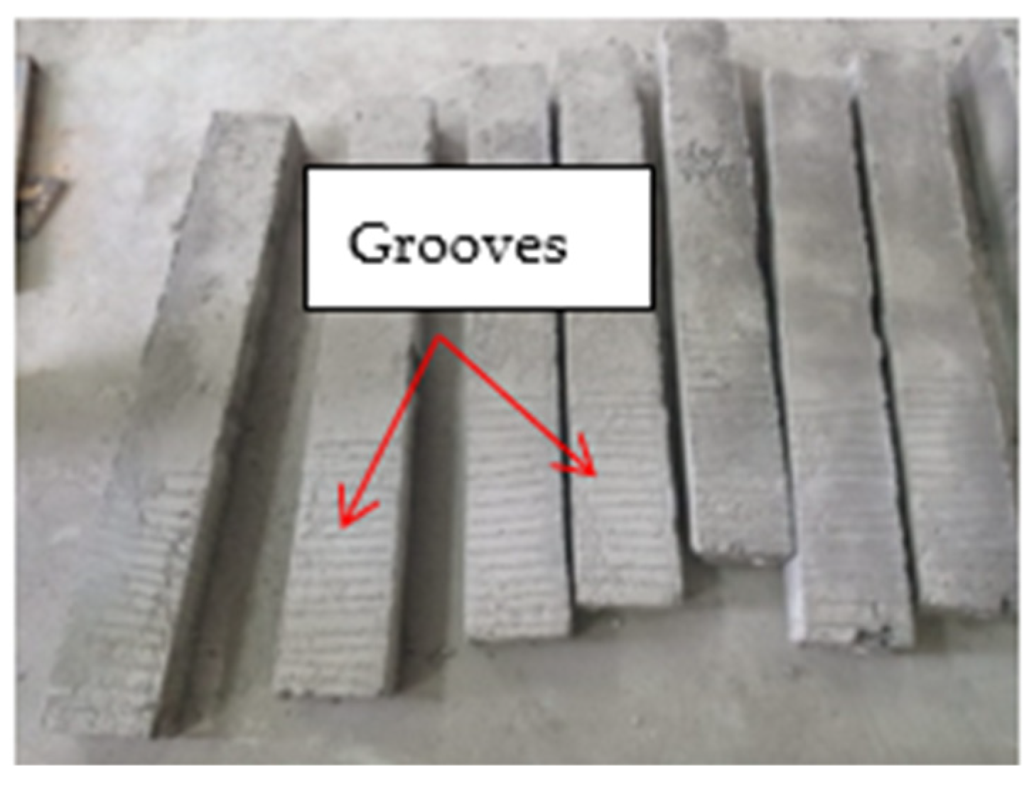
Figure 9b, the increase in the ratios of the Pu compared to control beam B0 reached 32, 51 and 70%, respectively, when one, two and three layers of SMF were applied to the beams BD1, BD2 and BD3. The reason is that when these beams were previously loaded, the diagonal shear explosion was opened. After removing the load, this crack was almost locked again. Due to the absence of stirrups in this area, the shear crack opened quickly and the lock was restored quickly because there was no lengthening of the internal reinforcement. When the sides of the beam were roughened and dense reinforcement was applied inside the SHCC, the beam worked efficiently. The layers of reinforcement prevented the old crack from opening, and the beam worked well.
3.3.2. Effect of Damaging
In groups C, D and E, the damaged beams BD1, BD2 and BD3 were compared with their counterparts without damage, B1, B2 and B3. The undamaged beams B1, B2 and B3 outperformed the damaged beams BD1, BD2 and BD3. The Pu of beam B1, which was supplied by a single layer of SMF within the SHCC, was 11% more than the Pu of beam BD1, which was similarly supplied with a single layer of SMF within the SHCC. Beams B2 and B3’s Pu performed approximately 10% better than that of the damaged beams BD2 and BD3. As a result, the damage to the beams was absorbed in the large negatives in the maximum load and compared to their counterparts properly. The reason is that the contribution of the original concrete to the damaged beams was reduced due to the crack that occurred in them before strengthening. Therefore, the strengthening layers are responsible for bearing the shear force.
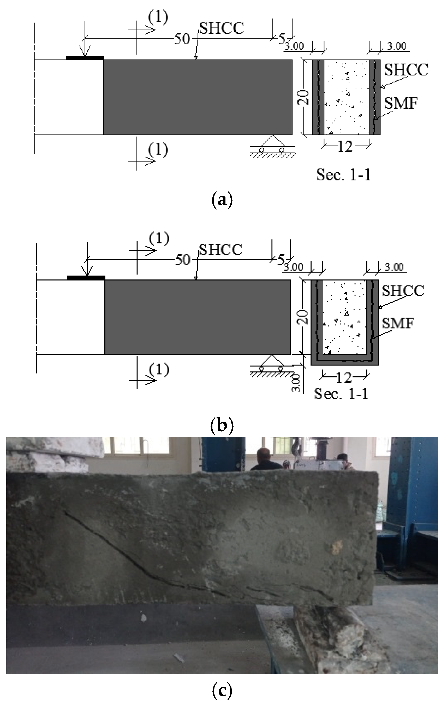
3.3.3. Effect of Wrapping
In group F, the effect of strengthening layers wrapped around the beam’s body is discussed. Two damaged beams BD1 and BDU1 that were reinforced with a single layer of SMF within the SHCC layer were compared. There was a single difference between these two beams when there was an existing additional bottom layer of SHCC at the soffit of the beam BDU1. The U-shaped form of SHCC was applied to the beam BDU1 while the beam BD1 was strengthened only at the two sides. It is known that there is no benefit in implementing a strengthening layer on the soffit or top surface of the beam to resist shear stresses because the direction of the shear stresses is vertical in the direction of the sides of the beam. Therefore, strengthening layers are implemented on the sides of the beam in the direction of the shear forces in order to resist the shear and improve the beam’s capacity as a result of the strengthening. In contrast to this, the current study demonstrated a significant improvement in the shear capacity of the beam BDU1 that contained strengthening at the sides and bottom. The Pu of the beam BDU1 was 30% higher than that of the beam BD1.
The reason is not because the bottom layer in the beam BDU1 bears part of the shear force, but rather because the bottom layer increases the cohesion between the layers of the sides and the original concrete of this beam. At high loading rates, the side layers begin to gradually separate from the beam, causing premature collapse before the supporting layers reach their capacity. The presence of the bottom layer connects the side layers and prevents them from separating, so collapse is delayed and the maximum load of the beams increases. The layers of the beam BDU1 were also reinforced with a continuous mesh on the sides and bottom (U-shaped), which led to a strong SHCC layer and difficulty separating from the original concrete of the beam BDU1. The findings in this research proved the viability and efficacy of employing SHCC reinforced with SMFs at varying quantities as a strengthening strategy for reinforced concrete precracked beams prone to shear failure. These straightforward yet efficient techniques could improve the caliber and safety of current concrete structures while saving a substantial amount of time and work.
3.4. Ultimate Displacement
3.4.1. Effect of SMF Amount
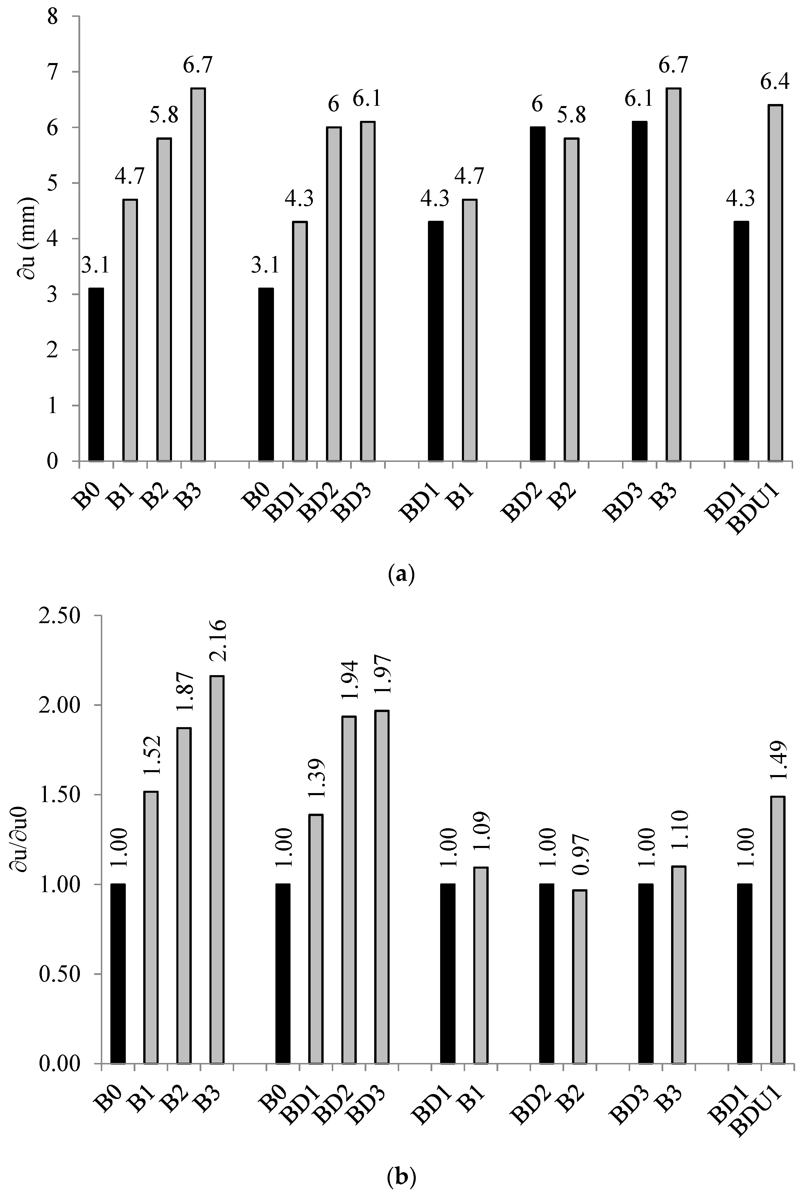
Just as the efficiency of beams is measured by the load capacity, deflection is a very important factor in determining the efficiency of beams in deforming. The greater the flexibility of the beams before collapse, the longer it takes until the beams exhibit ductile behavior. Codes impose limits on the deformation of the beams, so the deformation must be studied in addition to the strength of strengthened beams. As a result, the purpose of this section was to investigate the impact of the SMF quantity on the final displacement (∂u) of both damaged and undamaged beams. As seen in
Figure 10a, the ∂u of the beams improved more as the number of SMFs increased. The unweakened beam B0 had a ∂u of 3.1 mm, but the strengthened beams B1, B2, and B3 had ∂u values of 4.7 mm, 5.8 mm, and 6.7 mm, correspondingly. As can be seen in
Figure 10b, when one, two, and three layers of SMF were applied, the increase in the ratios of the ∂u relative to control beam B0 reached 52, 87, and 116%, respectively. It is seen that an increase in SMF quantity clearly enhanced the shear capacity and deformation of the strengthened beams B1, B2, and B3. This is because the strength of the layer on the sides of the beam to withstand the tensile force produced as a result of the shear force increases with the number of SMF layers. The more diagonal shear cracking that the layer can tolerate, the more it delays the crack from opening, and preventing the crack from opening increases beam deflection. All of these factors add up to an increase in the maximum deflection of the reinforced beams B1, B2, and B3. The deflection increased when the beam broke later in its lifespan.
The outcomes of group B demonstrated that beams BD1, BD2, and BD3, which had previously sustained damage, could engage in more deformation. When the beams BD1, BD2 and BD3 were strengthened, the ∂u rose dramatically compared to the reference B0. As seen in
Figure 10b, when single, double, and triple layers of SMF were applied to the beams BD1, BD2, and BD3, the increase in the ratios in the ∂u relative to control beam B0 reached 39, 94, and 97%, respectively. The beams achieved improved deformations when their sides were roughened and thick reinforcement was added inside the SHCC. The beam functioned successfully because of the layers of strengthening that kept the original crack from opening.
3.4.2. Effect of Damaging
The ∂u of the damaged beams (BD1, BD2, and BD3) in groups C, D, and E were com-pared with those of their counterparts that were not damaged (B1, B2, and B3). In comparison to the damaged beams BD1, BD2, and BD3, the ∂u of the intact beams B1, B2, and B3 was marginally higher. A single layer of SMF inside the SHCC provided the ∂u of beam B1, which was 9% more than the ∂u of beam BD1, which was also produced by a single layer of SMF within the SHCC. The ∂u of beams B2 and B3 was around 7% higher than that of the damaged beams BD2 and BD3. The reason is that the contribution of the original concrete to the damaged beams was reduced due to the crack that occurred in them before strengthening. Therefore, the strengthening layers are responsible for bearing the shear force.
3.4.3. Effect of Wrapping
The impact of reinforcement layers encircling the beam body on the ∂u was examined in group F. The ∂u of beam BDU1 was 49% greater than that of beam BD1. This is not because the bottom layer of beam BDU1 made the layers of the sides and the original concrete of this beam more cohesive. The maximum deflection of the beam as it rises and collapses is postponed due to the bottom layer’s ability to join and keep the side layers from splitting.
3.5. Energy Absorption Capacity
The energy required to conform a particular specimen to a particular strain is known as the energy absorption capacity. Furthermore, a material’s energy capacity is its ability to both store and absorb energy. The area under the load-displacement curve in the current investigation was used to define the concrete’s energy absorption capacity (E). Examining how strengthening affected the tested beams’ E value was crucial. One of the concrete beams’ ductility indicators is E. Greater energy signifies a greater capacity to build before breakdown.
3.5.1. Effect of SMF Amount
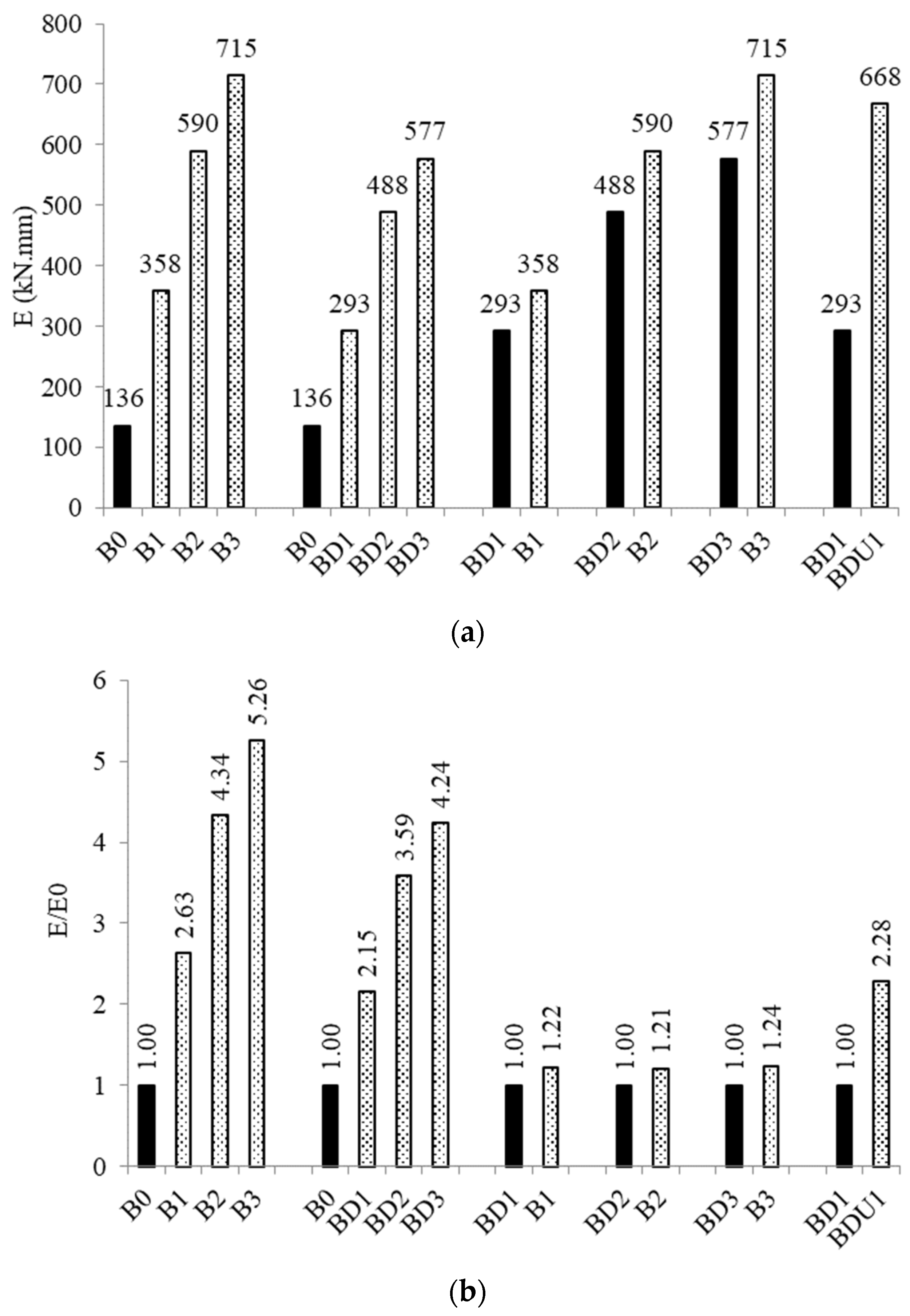
This section’s goal was to look into how the SMF amount affects the energy absorbed (E) in the beams that are damaged and those that are not. The E of the beams was obviously enhanced more as the quantity of SMFs increased, as seen in
Figure 11a. The reinforced beams B1, B2, and B3 had E values of 358 kN.mm, 590 kN.mm, and 715 kN.mm, respectively, whereas the control beam B0 had an E of 136 kN.mm. Applying one, two, or three layers of SMF resulted in an increase in the ratios in the E relative to control beam B0 of 163, 334, and 426%, respectively, as shown in
Figure 11b. It is evident that the E of the reinforced beams B1, B2, and B3 was significantly raised by an increase in the SMF amount. This is due to the fact that as the number of SMF layers increases, the high strength of the SHCC layer reinforced with SMFs on the beam’s sides to withstand the tensile force generated by the shear force increases, improving the area under the load-deflection curve.
Group B’s results showed that greater energy may be absorbed by damaged beams BD1, BD2, and BD3. In comparison to the reference B0, the E increased when the beams BD1, BD2, and BD3 were reinforced. Applying single, double, or triple layers of SMF to beams BD1, BD2, and BD3 resulted in enhanced ratios in the E relative to control beam B0 of 193, 388, and 477%, respectively, as can be seen in
Figure 11b. When substantial reinforcement was put within the SHCC and the sides of the beams were roughened, the E beams saw these significant gains. The layers of strengthening that prevented the original crack from opening allowed the beam to work properly.
3.5.2. Effect of Damaging
Groups C, D, and E compared the E of the damaged beams (BD1, BD2, and BD3) with those of their corresponding beams B1, B2, and B3. The E of beams B1, B2, and B3 was somewhat greater than that of the damaged beams BD1, BD2, and BD3. The E of beam B1, which was created by a single layer of SMF inside the SHCC, was 22% greater than the E of beam BD1, which was likewise produced by a single layer of SMF inside the SHCC. The difference between the E of the damaged beams BD2 and BD3 and the beams B2 and B3 was about 20%. The explanation is that the crack that developed in the damaged beams prior to strengthening decreased the original concrete’s contribution to the damaged beams. Consequently, the shear force must be supported by the strengthening layers.
3.5.3. Effect of Wrapping
In group F, the effect of the surrounding reinforcement layers on the E was investigated. The ∂u of the beam BDU1 was 128% higher than that of the beam BD1. This is not because the original concrete and side layers of beam BDU1 were more cohesive due to the bottom layer; it is because the bottom layer may unite and prevent the side layers from separating, and therefore the E of the beams rises and collapse is delayed.
4. Analytical Prediction of Load Capacity
In this section, the shear strength of the beams was predicted. Based on the testing setup showed in
Figure 6, the shear force acting on the right shear span of the beam equals 0.64 times the ultimate load (P
u,exp), as shown in following equation:
The ultimate shear (V
u) of the tested beams was estimated using the ACI [
38] formulas. Equation (2) was used to get the concrete’s nominal shear strength (V
c). The impact of the shear span to depth ratio (a/d) on the nominal shear strength (V
c) of RC beams was investigated by Kani [
39].
where
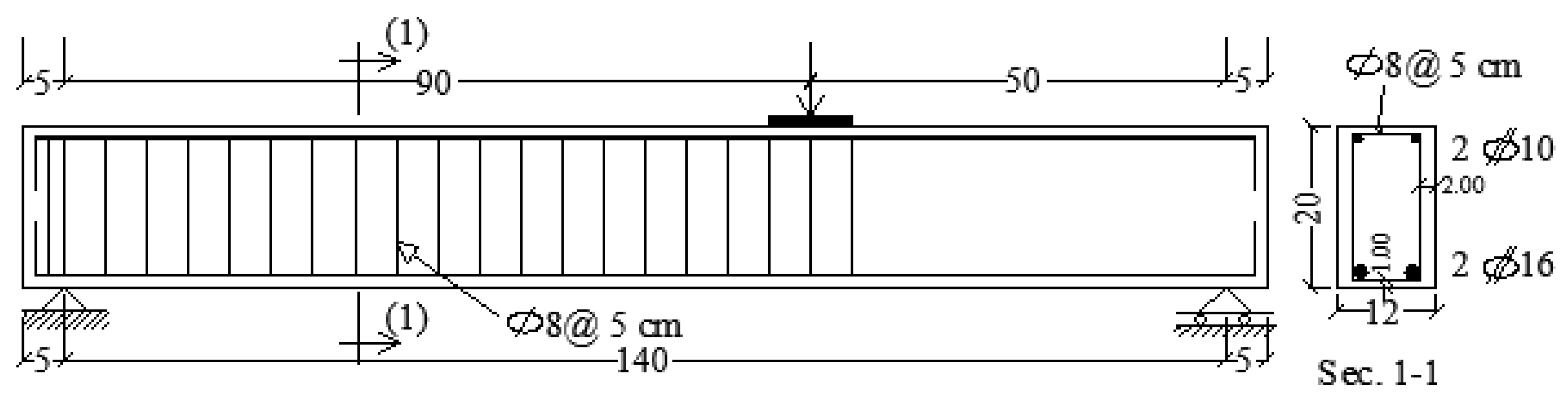
fc is the compression response of the concrete, b is breadth of the beam (120 mm), d is the effective depth of the beam (174 mm), and according to Kani [
39], it was obtained that β = 0.33 at a/d equals 500 mm/174 mm = 2.87.
For substrate concrete beams,
fc is 29.4 MPa, b is 120 mm, and d is 174 mm. After application of Equation (2), the predicted ultimate shear (V
c) of the control beam (B0) was 37.3 kN. The procedures of calculating the shear strength provided with the SHCC layers are divided into two steps. The first is the SHCC layer (V
SHCC) while the second is the steel mesh fabric (V
SMF). Firstly, the shear strength resisted by the SHCC layer can be estimated via the equation below [
40]:
where
is the compressive strength of the SHCC (56 MPa);
is the breadth of the SHCC layers on both sides of the beam (60 mm); and
is SHCC height (200 mm).
After application of Equation (3), the predicted ultimate shear (V
SHCC) of each strengthened beam was 16.16 kN. V
SMF provided by the SMF inside the SHCC layers was calculated using the following equation:
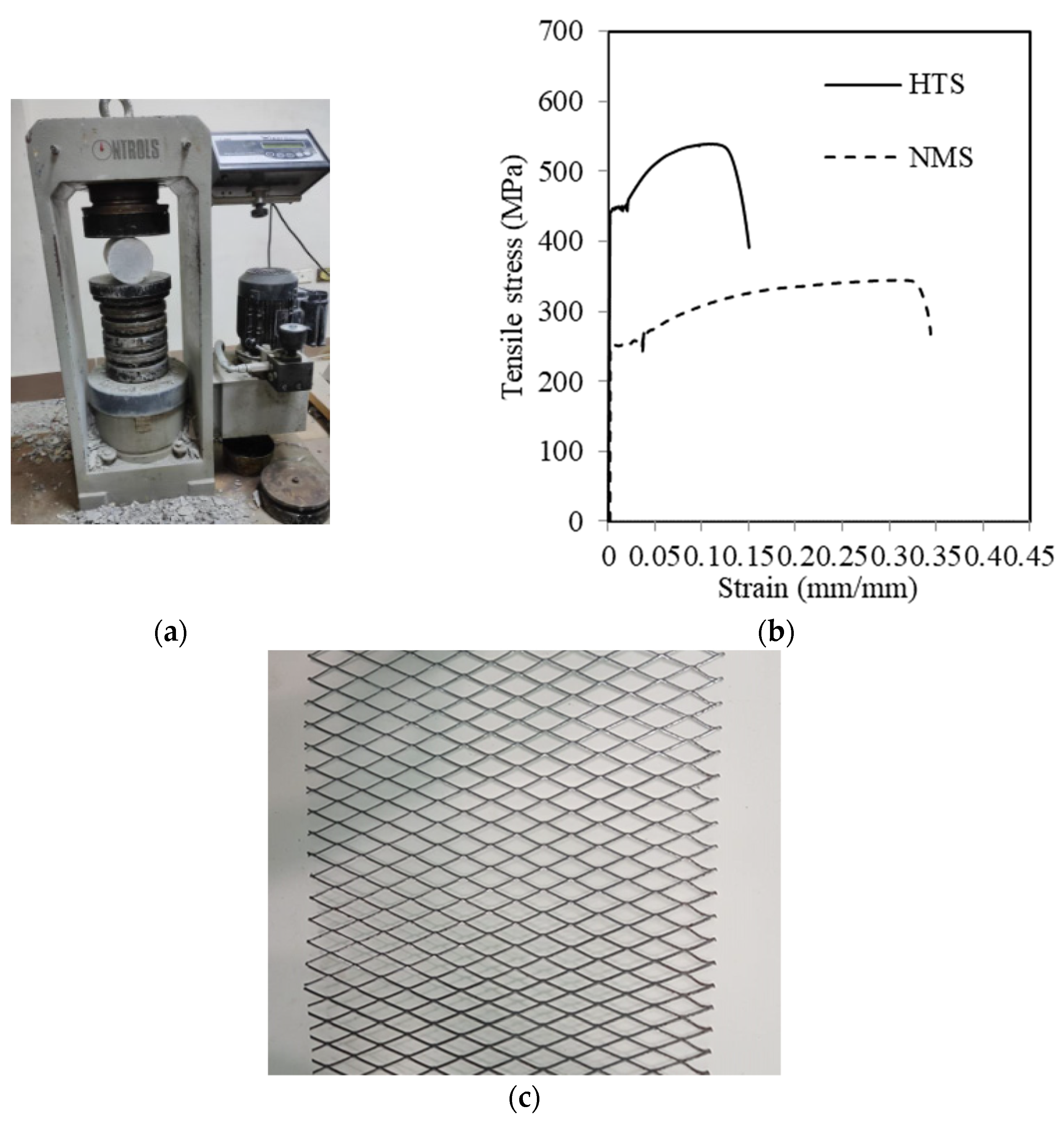
where
fy is the specified yield strength of SMF (285 MPa), d
v is the height of SMF (180 mm), and A
v is the area of SMF within spacing S (70 mm). A
v was calculated using the following equation:
where N is the number of SMF layers on both sides of the beam. A
s is the cross-sectional area of the SMF strand (3.2 × 2.1 mm = 6.7 mm
2).
In order to take into consideration the debonding action between the SHCC layer and the beam sides, the suggested correction factor (α = 0.5) is presented in this work. The following is how the correction factor is incorporated into the shear strength calculation:
The anticipated ultimate shear strength (V
up) of the tested beams was estimated using Equation (6), taking factor α into account. The implementation of this correction factor significantly improves the predictive accuracy of the analytical models, as listed in
Table 3, by matching the ratio range of the analytical findings with the experimental predictions (
) equals 0.93–1.12. The anticipated and actual shear strengths were more aligned as a result.
5. Conclusions
Sustainable and cost-effective optimization of shear strengthening techniques improves the efficiency of construction projects by reducing resource consumption, lowering expenses, and enhancing RC structures. Concrete components always need to be repaired due to the deterioration of construction materials and the increased design load. Exceptional ductility, strength increase during cracking, and recurring controlled-opening crack creation are characteristics of SHCC. By strengthening SHCC with steel metal mesh, this study aimed to enhance its properties. Moreover, the purpose of this work was to investigate the impact of adding SMF layers to strengthen SHCC on the shear capacity of both damaged and undamaged RC beams with shear defects. Eight reinforced concrete beams underwent preparation, strengthening, and testing under bending stresses. Before any strengthening could be applied, four of them cracked. The beams measured 120 mm in width, 200 mm in height, and 1500 mm in length. There were one, two, or three SMFs applied. The SMF had a density of 2.7 kg/m2. The whole shear span of the beams was reinforced on both sides. SHCC in the U-shape was also carried out. The SHCC had walls that were 30 mm thick. Discussions were held about strengthened beam failure, load-deflection response, ultimate load, ultimate displacement, and energy absorbed. The following were noted as the primary conclusions:
When one, two, or three layers of SMF were applied within the SHCC layer, the ultimate load of the strengthened beam increased by 47, 57, and 90%, respectively, in comparison to an unstrengthened beam. Increases in the ratios in the ultimate load reached 32, 51, and 70%, respectively, when one, two, and three layers of SMF were applied to the identical beams that had been damaged prior to strengthening.
The increase in the ratios in the ultimate deflection of strengthened beams compared to control beam B0 were 52, 87, and 116%, respectively, when one, two, and three layers of SMF were applied.
The ultimate load of the undamaged beam was about 11% more than that of a damaged beam, which was similarly supplied by single, double or triple layers of SMF within the SHCC.
The final deflection of the undamaged beams was somewhat higher than that of the damaged beams that were reinforced with varying numbers of SMFs within SHCC.
When comparing the shear capacity of the damaged beam with bottom and side strengthening (U-shaped) to the damaged beam with side strengthening only, there was a notable 30% improvement. Furthermore, the deflection of the U-shaped beam was 49% higher than that of the beam having only SHCC at the sides.
Applying one, two, or three layers of SMFs within SHCC resulted in increases in the ratios of the energy absorbed by the strengthened beams relative to the control beam of 163, 334, and 426%, respectively.
A correction factor (α = 0.5) was applied to the predicted shear strength to account for the debonding effect between the SHCC layer and the beam sides. This adjustment significantly enhanced the accuracy of the analytical models, aligning the mean ratio of the analytical predictions with the experimental results.


 ,
, 

