Article

Influence of Bracing Systems on Pile Design Parameters: A Structure–Soil–Pile Interaction Approach

Civil Engineering Department, Nigde Omer Halisdemir University, 51240 Niğde, Türkiye
*
Author to whom correspondence should be addressed.
Buildings 2025, 15(5), 764; https://doi.org/10.3390/buildings15050764
Submission received: 22 January 2025 / Revised: 18 February 2025 / Accepted: 24 February 2025 / Published: 26 February 2025
(This article belongs to the Section Building Structures)

Abstract

Structural damages occurred during any earthquake arise not only from structural design flaw but also from the variability of sub-base soil behavior and the foundation system. For this reason, structure–soil–pile interaction has an important place in evaluating the behavior of a structure under dynamic effects. Bored pile application, which is one of the deep foundation systems, is a widely used method in the world to transfer the loads coming from the structure to the ground safely in problematic grounds. For this reason, in pile foundation system designs, how bored pile foundation systems will affect the structural design under earthquake loads is considered an important issue. In particular, how diagonally braced steel structures with piled raft foundation systems will behave under earthquake effects has been evaluated as a subject that needs to be examined. For this reason, this situation was evaluated as the main purpose of this study. The effect of the bored pile systems designed in different orientations on the behavior of diagonally braced steel structures during an earthquake under kinematic and inertial effects was investigated in detail within the scope of this study. Numerical analyses, based on data from shake table experiments on a scaled superstructure, examine various pile design scenarios. Experimental base shear force measurements informed the development of numerical scenarios, which varied pile lengths and inter-pile distances while maintaining constant pile diameters. This study analyzed the kinematic and inertial effects on the piles, offering insights into their structural behavior under seismic conditions. The increase in pile length and the increase in the distance between the piles caused a significant increase in the bending moment and shear force, which have an important place in pile design.

1. Introduction

Soil behavior analysis evaluates the dynamic response of the ground to earthquakes with varying magnitudes, frequencies, and durations under diverse soil conditions. These analyses also assess the transformation of seismic forces as they propagate from the bedrock to the surface. Local soil conditions significantly influence earthquake-resistant building design and geotechnical earthquake engineering. The mutual influence of soil and structural responses during dynamic effects is commonly referred to as soil–structure interaction (SSI) in the literature [1]. The dynamic behavior of a structure built on rigid soil is less than that of a structure built on soft or loose soil. Therefore, the importance of soil–structure interaction (SSI) has been emphasized in the design of the structure under dynamic effects in soft clay and liquefiable sandy loose problematic soils [2,3,4]. In cases where the bearing capacity of shallow foundations is exceeded, the loads from the superstructure are transferred to the ground via pile foundations. Another important task of pile foundations is to prevent damage to the structure under dynamic effects. For this reason, it is very important to predict the behavior of piles under dynamic effects and to design them under these effects. The response of the structure to dynamic effects is not only dependent on free field conditions but also on the properties of both the superstructure and substructure systems. In problematic soils, pile foundation systems are constructed to safely transfer the loads from the structure to the ground. In light of these developments, the concept of soil–structure–pile interaction (SSPI) has become widely used. In past case studies, it has been observed that bridges and buildings constructed with piled raft foundations have collapsed due to earthquake forces [5,6,7]. Most of these collapses were found to be caused by soil liquefaction or resonance in the structure overstressing the piles [8,9,10].
Research indicates that soil–structure interaction (SSI) analyses can be conducted using two distinct approaches. The first approach is the direct method, in which both the superstructure and the soil are idealized and modeled as a single integrated system. The second approach, known as the substructure method, differs from the direct method by modeling the superstructure and the soil environment separately [1,11].
Numerous studies have utilized laboratory-scale shaking table experiments to investigate soil–structure interaction. These experiments have been conducted using clay and sandy soil as scaled models. Additionally, a single-degree-of-freedom steel structure model has been tested in shaking table experiments to evaluate its dynamic response [12].
It has been noted that no single equation can comprehensively account for SSI, and neither dimensional analysis nor similarity theory can be directly applied to replicate real-world conditions in scaled models. Therefore, shake table experiments aim to simulate primary forces while minimizing secondary effects by adhering to established scaling methods from the literature [6].
Many structural systems have been used in building design [13,14,15]. Rigidity is an important concept in multi-story buildings. Various methods are used to increase the stiffness in multi-story buildings. The seismic performance of centrally placed steel diagonal-braced systems and X-braced systems under repeated loads was investigated, and maximum ductility was obtained [16]. Soil–structure interaction (SSI) is an important factor in the seismic performance of structures, especially when considering steel diagonal bracing systems for structural strengthening. Shake table tests are essential to evaluate the behavior of these systems in the laboratory and under seismic conditions. Numerous studies have investigated the behavior and performance of different bracing systems, including diagonal, X, and combination bracing, in increasing the seismic resistance of structures [17,18,19]. Steel bracing plays a key role in stabilizing the structural system and reducing lateral load effects, thus improving the overall seismic performance of buildings [20]. Research has also shown that steel diagonal bracing systems can reduce displacement and natural periods, thus improving the structural response to seismic forces [17].
Shake table tests and numerical analyses have been very important in evaluating the seismic performance of various bracing systems, including self-centering energy-dissipating braces, concentric braced frames, and other innovative bracing configurations [21,22,23]. These tests provide valuable information on the behavior of structures under seismic conditions, helping researchers and engineers to optimize designs against dynamic effects. In later studies, the optimum distributions of steel diagonal bracing systems were determined using certain limiting effects [24].
Under dynamic effects, kinematic and inertial interactions occur between the soil, pile foundation, and structure. Inertial interaction analyzes the effect of the superstructure on pile foundations under dynamic effects. This interaction has shown that the forces from the superstructure are more effective in the pile–soil interaction, especially in dry sandy soil conditions [25]. Kinematic interaction analyzes the effects of soil on piles under dynamic effects. Kinematic interaction can cause significant stress on piles, especially in stratified soils with different characteristics [26,27]. Kinematic interaction analyses are significantly affected by the inhomogeneity and nonlinearity of the soil, which can significantly affect the soil effects and the bending forces on the piles [28]. Combining kinematic and inertial interaction analyses has an important role in understanding the behavior of pile rafts under dynamic effects. Studies have shown that bending moments in piles can occur at different depths depending on the combination of kinematic-inertial forces and constraints in the pile caps [3]. Shaking table tests and 3D numerical and experimental studies have validated models predicting kinematic–inertial interactions and effects on structures [25,29]. The behavior of pile raft foundations in stratified soils has been investigated via kinematic interaction analyses by considering soil stiffness, layer thickness, and pile orientations under seismic effects [29,30]. It was observed that pile bending moments were affected by kinematic and inertia analyses in layered structures such as soft clay layers on dense sand soil [31].
In order to examine the effect of the results obtained from uniaxial shaking table tests on the foundation design of multi-degree-of-freedom structures in terms of SSPI analysis, it was observed that shaking table tests were missing in the literature. Most of the studies in the literature have been carried out by concentrating on the mass at one point in a single-degree-of-freedom structures. This is a situation in which accurate results cannot be reflected since high modes cannot be detected in structure–ground interaction analyses [32]. The effect of diagonal steel members, which are frequently used in multi-story steel structure designs to minimize earthquake effects and increase the stiffness of the structure, on the foundation behavior of the structure using inertial and kinematic interaction analyses in terms of soil–structure–pile interaction analysis has not been investigated with the help of scaled shaking table experiments in previous studies. In particular, how diagonally braced steel structures with piled raft foundation systems will behave under earthquake effects has been evaluated as a subject that needs to be examined. For this reason, this situation was evaluated as the main purpose of this study. The effect of the bored pile systems designed in different orientations on the behavior of diagonal braced steel structures during an earthquake under kinematic and inertial effects was investigated in detail within the scope of this study. Numerical analyses, based on data from shake table experiments on a scaled superstructure, examine various pile design scenarios. In the shake table experiments for the superstructure, a 10-story, single-span structure scaled 1/15 was tested with and without braces, and the total base shear forces at the base were calculated from the story shear forces obtained at each story for inertia analyses during earthquakes. Experimental base shear force measurements informed the development of numerical scenarios, which varied pile lengths and inter-pile distances while maintaining constant pile diameters. This study analyzed kinematic and inertial effects on the piles, offering insights into their structural behavior under seismic conditions. With the help of the story shear forces obtained because of the shaking table tests, the base shear forces at the base are determined, and their effects on the pile design parameters are analyzed numerically with the help of the obtained data. Shaking table experiments on the dynamic effects of three different earthquake data from the bedrock to the surface were tested with and without braces applied to a 10-story, single-span steel structure formed with the help of a shaking table. The data obtained were analyzed using the finite element method for different pile lengths and inter-pile distances in stratified soil modeled in a numerical environment under different earthquakes by performing 36 separate numerical solutions. The effects of bracing systems on pile design in multi-degree-of-freedom structures, the effect of increasing inter-pile spacing, and changes in pile lengths on the bending moment and shear force on piles are investigated.

2. Materials and Methods

2.1. Experimental Setup

Performance-based seismic design represents a modern approach to earthquake-resistant design, prioritizing structural performance over mere strength. SSI has been identified as advantageous under seismic loads, as it prolongs the structure’s natural period and enhances damping. This study investigates SSI experimentally by analyzing the effects of structural elements on soil behavior. While replicating full-scale structures in laboratory settings is challenging, critical components can be simulated through small-scale physical models.
Scale models may satisfy their similarity to the prototype model to different extents, and researchers may give the model names such as real, adequate, or distorted [2]. Meymand (1998) et al. emphasized that no equation can be written to jointly satisfy the soil–structure interaction, nor can dimensional analysis or similarity theory be directly applied to this complex system to obtain the similarity of the scaled model to the real model. Therefore, to create a scaled model and use the scaling method in Table 1, which is accepted in the literature, it aims to successfully model the primary forces in the system and to create an adequate model by suppressing secondary effects [6]. In this study, the method proposed in the literature is used with a scaling factor of λ = 15.
In the experimental setup, as shown in Figure 1, a 10-storey (30 m), single-span (3 m), equal-story-height (3 m), moment-resisting steel structure was designed by scaling at the scaling ratio (λ = 15). The total mass of the structure is 14 kg. The columns of the scale model are 0.25 m wide and 0.03 m thick. The slabs are 0.25 m wide, 0.25 m long, and 0.01 m thick. The plate used for fixing the shaking table at the base is scaled to be 0.4 m wide, 0.4 m long, and 0.03 m thick.

2.2. Response Spectrum of the Model and Selection of Earthquake Records

To investigate SSI behavior under seismic effects, the response spectrum of the structure was experimentally determined under harmonic loading, varying frequencies from 0.1 s to 5 s in increments of 0.1 s while maintaining constant acceleration and damping ratios. Following this, the Peer Ground Motion database was utilized to identify three earthquake scenarios with distinct characteristics relevant to the bedrock’s expected behavior, using peak accelerations as a key criterion.
While determining the earthquake data, in addition to the response spectrum data of the structure, earthquake selection was made by considering the distance and proximity to the center, magnitude (R) values between 7 and 7.5, and peak ground acceleration (PGA) values. Each experimental model was subjected to two mid-distance earthquakes, Manjil Abbar (1990) and Hektor Mine (1998), and one close-distance earthquake, Düzce (1999). The information about the earthquake data is summarized in Table 2.
The ground environment where the structure will be constructed is a sandy soil consisting of 3 layers of silt, clay, and gravel, as shown in Table 3. The first layer is SM (silty sand) with saturated unit volume weight Ɣsat = 16 kN/m3 and shear wave velocity Vs = 150 m/s for 30 m; the second layer is SW (well-graded sand) with saturated unit volume weight Ɣsat = 18 kN/m3 and shear wave velocity Vs = 350 m/s for 30 m, and the third layer is GM-SM (sandy–gravelly silt) with saturated unit volume weight Ɣsat = 20 kN/m3 and shear wave velocity Vs = 630 m/s in the layer, as well as a soil profile with Ɣsat = 22 kN/m3 and shear wave velocity Vs = 760 m/s in the bedrock [6]. The shear wave velocity used for the analysis in this study was obtained through MASW analysis based on the cross-hole geophysics method.
The scaled values of the soil environment where the structure will be constructed at λ = 15 regarding Table 1, as shown in Table 3, is a sandy soil consisting of a silt–clay–gravel layer. The first layer is SM (silty sand) with saturated unit volume weight Ɣsat = 16 kN/m3 and shear wave velocity Vs = 38.73 m/s for 2 m; the second layer is SW (well-graded sand) with saturated unit volume weight Ɣsat = 18 kN/m3 and shear wave velocity Vs = 90.37 m/s for 2 m, and the third layer is GM-SM (sandy-gravelly silt) with saturated unit volume weight Ɣsat = 20 kN/m3 and shear wave velocity Vs = 162.66 m/s, as well as a soil profile with Ɣsat = 22 kN/m3 and shear wave velocity Vs = 196.21 m/s at bedrock.
In many studies, laboratory scale shaking table tests have been conducted to determine the soil–structure interaction (SSI). Shaking table experiments were performed using clay soils and sandy soils as scaled soils. In addition, a single-degree-of-freedom steel structure model was tested in the shake table experiments [12]. The shear wave velocity and layer thickness were scaled within the soil using a scaling ratio of 1/15 as recommended in the literature. The frequency and period values of both the case soil model and the scaled soil model were determined using the DeepSoil software V7.1. The soil profiles were modeled based on a nonlinear model with time domain analysis, utilizing the general quadratic/hyperbolic (GQ/H) model with unloading as the selected analysis method. In both cases, the stratified soil data presented in Table 3 were used, and the corresponding frequency and period values were obtained. The frequency and period of the real case soil profile were determined as 1.333 s and 0.75 Hz, respectively, while those of the scaled ground were calculated as 0.344 s and 2.904 Hz.
In this study, the bedrock is assumed to be at 90 m. With the help of the response spectrum of the structure in the bedrock, the earthquake data determined from the Peer Ground Motion database were moved to the ground surface with the help of the Deep Soil program for uniaxial shaking table experiments. The DeepSoil software V7.1, utilized in this study, was initially developed in 1998 based on the principles of one-dimensional soil behavior analysis. This software enables both equivalent linear and nonlinear analyses to be conducted in both the frequency and time domains. When transferring earthquake data from the bedrock to the surface, DeepSoil software V7.1 performs ground amplification calculations. During an earthquake, seismic waves generated by ground motions propagate through the soil layers and reach the surface via the bedrock, leading to an increase in wave amplitude. This amplification process depends on the characteristics of the soil layers and is analyzed using geotechnical databases, often supplemented with borehole data [33].
The earthquake data (a) before matching and (b) after matching were matched with the help of the Seismo Match program following the design spectrum, as shown in Figure 2. The SeismoMatch program was used to match the earthquake records to the design spectrum, as illustrated in Figure 2. The design spectra were determined based on borehole data, and the pre-selected earthquake records were adjusted accordingly using SeismoMatch. In this process, following the methodologies proposed in the literature, earthquake acceleration records were modified to fit the target response spectrum [34,35].
Simultaneously, in this study, earthquake data were selected by targeting a specific point and considering the influence of local ground conditions at that location. Accordingly, three earthquake records from nearby faults were chosen. In this selection process, prior studies [36,37] that highlight the effectiveness of SMA bearings in controlling the seismic response of structures, particularly under near-fault ground motions, were used as references.
In this study, seismic effects were realized by transporting selected real earthquake data from the bedrock to the surface. Like other parameters of the model, the real earthquakes to be applied to the structure should be subjected to scaling. The earthquake data used here are time-dependent and scaled using the scaling factors recommended in the literature [6]. Although the actual earthquake magnitudes are the same as the magnitudes of the scaled earthquake data, the earthquake durations should be reduced by a factor of 3.87, with λ1/2 compared to the actual earthquake durations. In other words, scaled earthquakes contain higher frequencies and lower durations. Scaled and unscaled acceleration records of the selected 3 earthquakes are shown in Figure 3a for Hektor Mine 1998, Figure 3b for Manjil Abbar 1990, and Figure 3c for Düzce 1999.

2.3. Shaking Table Experiments

The scaled structure was designed for the shake table experiments using the scaling data given in Table 1. A 3D model was created using 4 steel slats for the columns and steel plates representing the floor slabs. The thickness and width of the plates and slats were determined through a trial-and-error approach in a numerical environment to ensure compliance with the required natural frequency and mass values during the design process. The dimensions derived based on the scaling ratio (λ = 15) given in Table 1 were then tested in the experimental setup. The column dimensions were adjusted so that the frequency of the real structure was 1.053 Hz, while the frequency of the scaled structure was approximately 4.06 Hz. Subsequently, the slab’s thickness and the modulus of elasticity of the material were numerically determined to achieve the appropriate mass density in accordance with the scaling factor recommended in the literature [6,38]. The connections between the columns and floor slabs were welded together. The connection between the scale model and the shaking table was established using metal screws, as illustrated in Figure 4. Additionally, accelerometers were placed in the experimental setup to measure the peak accelerations at each floor, as shown in Figure 5.
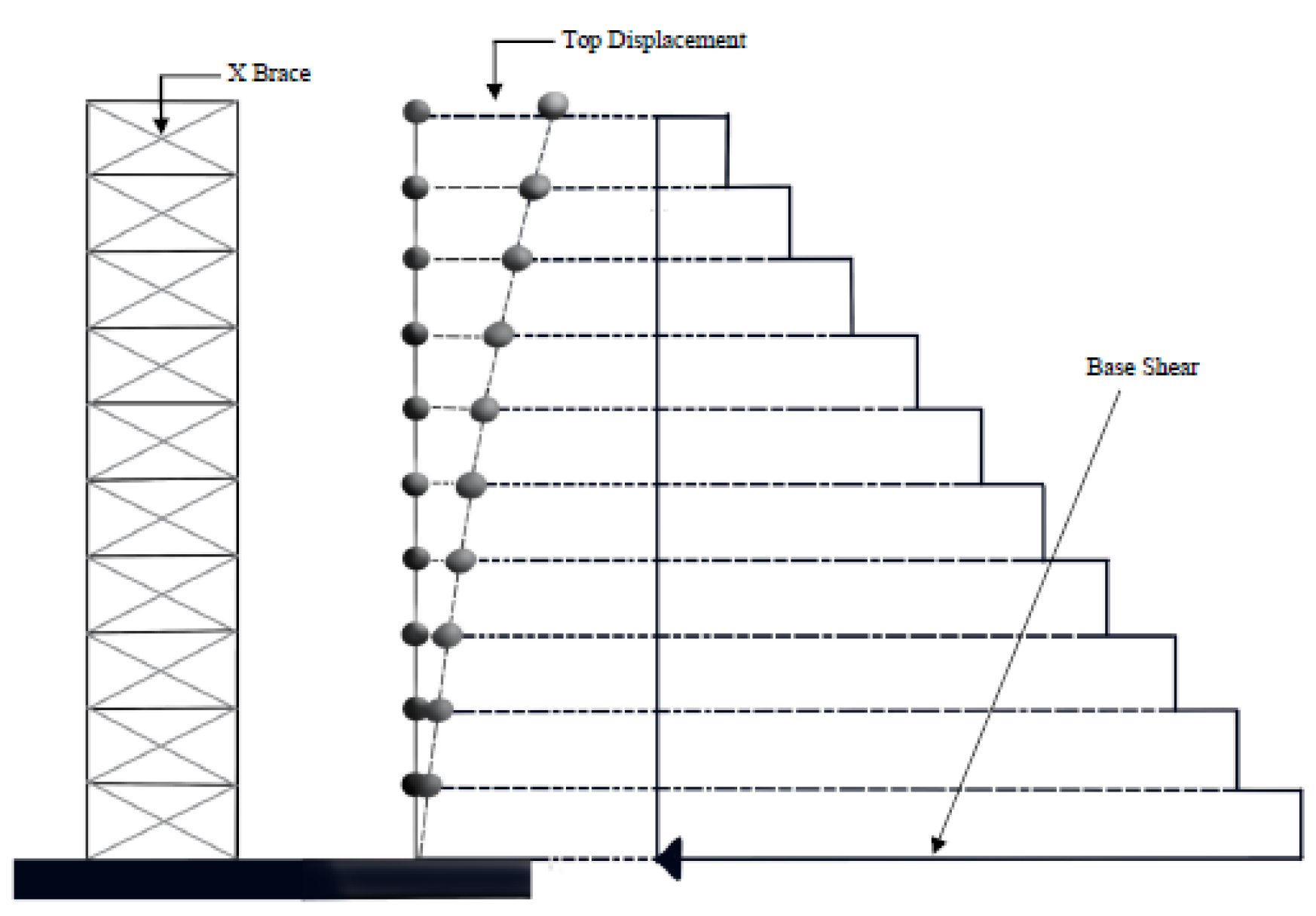
Kinematic and inertial effects are taken into account in structure–soil–pile interaction analyses. In this context, the stresses on the piles due to kinematic effects and the stresses on the structure due to inertial effects are determined and then combined. Consequently, the total bending and shear force effects on the pile elements are assessed for design purposes [25,29]. In this study, inertial and kinematic effects are analyzed separately to investigate the behavior of piles within the scope of SSI. As shown in Figure 4, the base shear forces required for inertia analyses were determined experimentally, independent of the kinematic analysis. Therefore, only the experimental setup of the structure and foundation is presented in Figure 4.
Initially, a harmonic loading test was applied to the model to determine its behavior in different modes and the natural frequency of the structure (1.053 Hz). The variation in peak acceleration and frequency of the scaled model under harmonic loading for the stories is shown in Figure 5.
As a result of the harmonic loading experiments, the behavior of the structure in different modes was determined numerically and experimentally in shaking table experiments. Figure 5 shows the peak accelerations of the floors in different modes experimentally. In order for a structure to behave safely and effectively under dynamic loads, dynamic parameters (frequency and modal analyses) were controlled [39]. After the dynamic adequacy of the scaled structure was ensured, the earthquake data of Hector Mine 1998 in Figure 3a, Manjil Abbar 1990 in Figure 3b, and Düzce 1999 in Figure 3c were applied to the uniaxial shaking table in a scaled manner, and the behavior of the structure and the base shear forces at the base were determined.

2.3.1. Shaking Table Experiments Using Steel Diagonal Support Members

In this study, bracings, which are X steel diagonal bracing systems, were used. Bracing is a structural support element used to strengthen the superstructure which increases the stiffness of the structure [1]. To evaluate the seismic performance of steel bracing systems in the experimental setup, X bracing systems were placed on each floor, as shown in Figure 5. A circular steel profile with a diameter of 2 mm and a modulus of elasticity of E = 200 GPa was used as the support members. In addition to the dynamically adequate scaled structure, X steel diagonal braces were placed on each floor, and the behavior of the structure and the base shear forces at the base were determined by applying the earthquake data of Hektor Mine 1998 in Figure 3a, Manjil Abbar 1990 in Figure 3b, and Düzce 1999 in Figure 3c to the uniaxial shaking table in a scaled manner.
The response of the steel building frame and structure used in the shaking table experiments is shown in Figure 6. It is also noticed that the natural frequency value of the braced structure (0.98 Hz) is shorter than the natural frequency value of the unbraced structure (1.053 Hz). This shows that the braced structure is more rigid than the unbraced structure [13].

2.3.2. Numerical Soil–Pile Interaction Analysis

The scaling procedures applied to the building model were also applied to the model piles. The slenderness ratio s/d, moment–curvature relationship, bending stiffness EI, relative soil–pile stiffness, yield strength, and natural frequency/period values that determine the pile response were considered to create a successful pile model [6].
As shown in detail in Table 4, the pile scaling ratio was determined as d = 0.053 m for the diameter of the model piles, l = 0.8 m and l = 2.4 m for the length of the piles, and s/d = 0.167 and s/d = 0.26 m to observe the effect of the distance between the piles. In previous studies, materials such as steel bars and RC were used to form piles [40,41,42]. In this study, aluminum pile material properties were used.
As shown in Table 5, the inter-pile spacing and pile lengths were changed, and the effect was analyzed numerically with the help of the data obtained experimentally from the superstructure using the Sap 2000 program V22. Kinematic interaction analyses were modeled as a plate element for the foundation and rod elements for the piles in SAP2000. In these analyses, the data obtained from p–y plateaus were applied to each pile as a link element in both directions, and push-over analyses were conducted. The shear forces and bending moments in each pile, obtained as a result of these push-over analyses, were then determined.
While modeling the pile raft in the Sap2000 program, nonlinear analyses were performed, and the effect of the superstructure on the piles was investigated using push-over analysis, taking into account the inertial and kinematic analysis approaches mentioned in the literature [25,29].
During the analysis, as depicted in Figure 7, the p–y values, which are used to evaluate the soil response in piles subjected to lateral forces, were applied to the springs. The shear forces and bending moments of the piles were then computed using the SAP2000 software. Here, p–y curves are employed to model the relative displacement relationship between the soil and the pile. For each pile–soil interaction, the cyclic loading conditions proposed by Reese were considered, and the PileLat program was utilized [43].

3. Test Results and Discussions

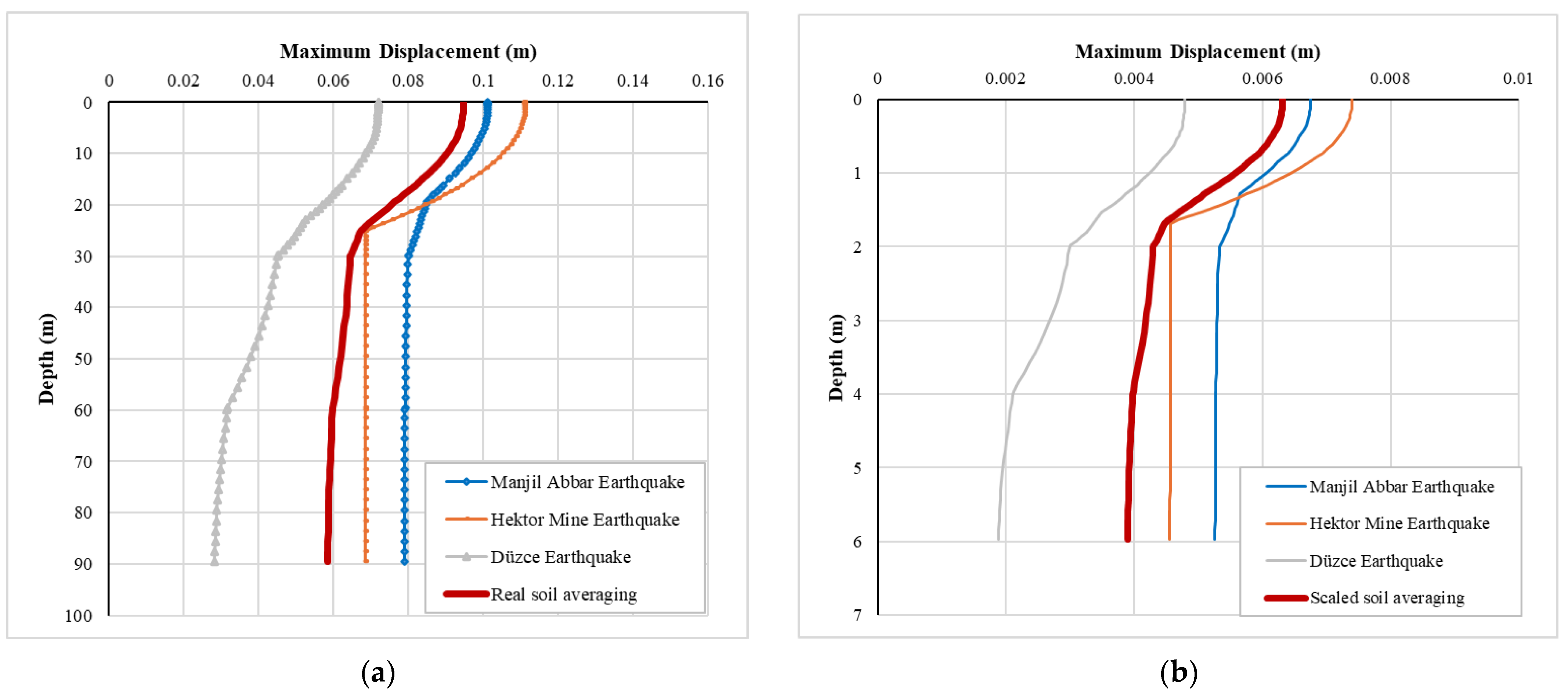
This study conducted shaking table experiments to evaluate base shear forces in SSI scenarios using X-braced steel systems. Three selected earthquake records were propagated from the bedrock to the surface, and maximum displacements along the soil depth were analyzed.
According to Figure 8, earthquakes are subjected to some changes depending on the characteristics of the ground as they move from the bedrock to the surface. For example, the Manjil Abbar Earthquake makes a displacement of 0.03 m when it moves from the bedrock to the surface. Similarly, the Hektor Mine Earthquake displaces approximately 0.04 m when moved from the bedrock to the surface, and the Düzce Earthquake displaces approximately 0.05 m when moved from the bedrock to the surface. This may occur because of the natural frequencies of the applied earthquakes. The superstructure may be subjected to extra displacements due to the ground conditions, causing it to approach closer to the resonance state. This is similar to the phenomenon that occurred in structures around the lakes of Mexico City during the 1985 Mexico City Earthquake. Here, the dominant period value of the earthquake recorded on the ground surface approached the natural period value of the structure, and it triggered the resonance state of the structure and caused more damage with the effect of the ground [44,45].
As it is seen here, the site conditions show that different earthquakes will be subjected to different displacements along the depth. This is an important factor for soil–structure interaction. If the superstructure is designed with earthquakes coming directly from the bedrock and the ground is ignored, it means that the extra displacements in the ground are ignored, which will cause extra stress between the structure and the soil, which may cause damage between the foundation and the structure.
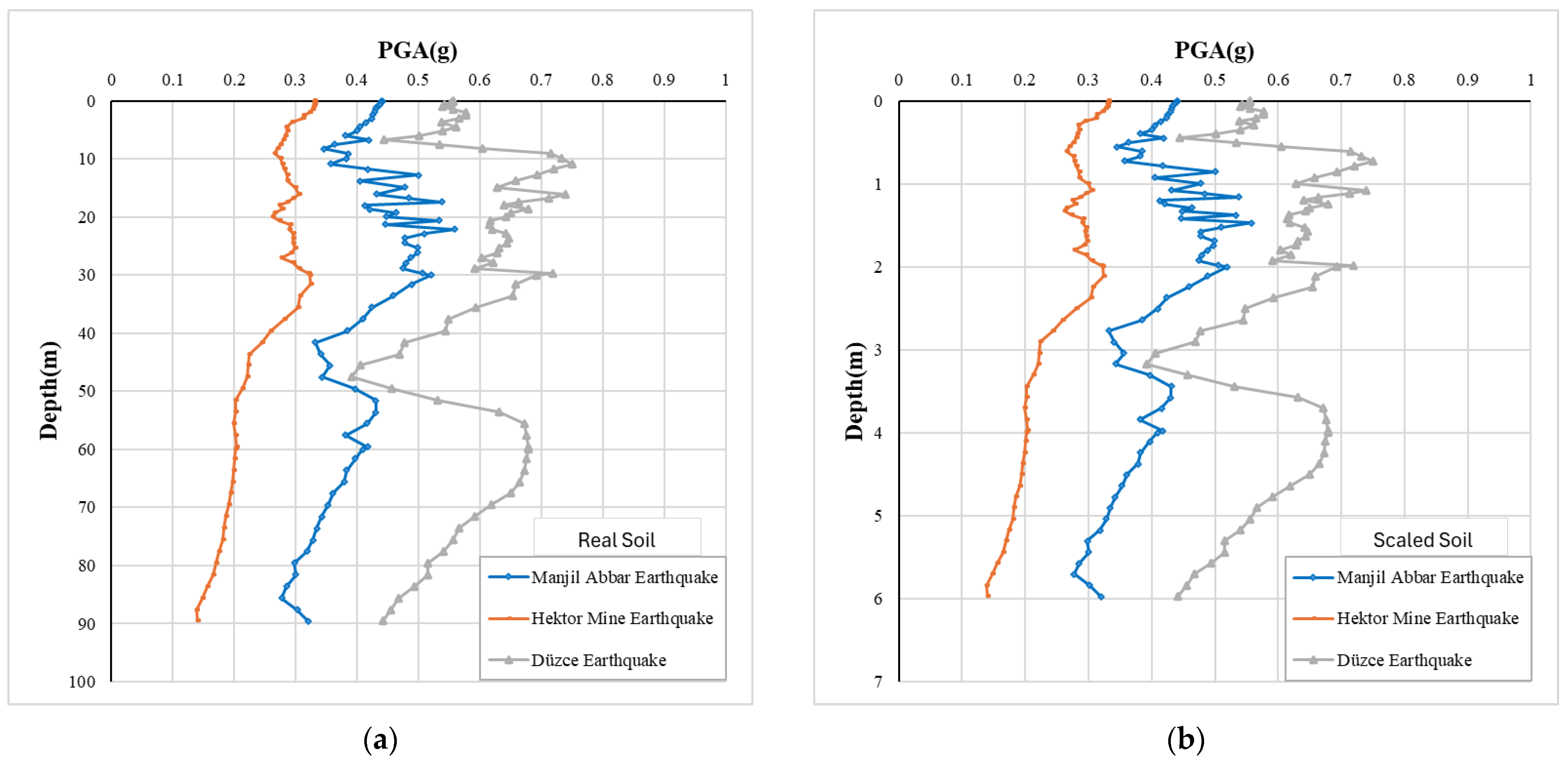
In Figure 9, three different earthquakes were carried from the bedrock to the surface, and the variation in peak accelerations with depth was analyzed.
In Figure 10, the variation in maximum strains with depth is analyzed for the three earthquakes. Considering the maximum strain rate in the first layer with a depth of 30 m, it is observed that there will be a risk of liquefaction in the ground. This situation is of great importance for the design of the structure and the foundation system to be selected.
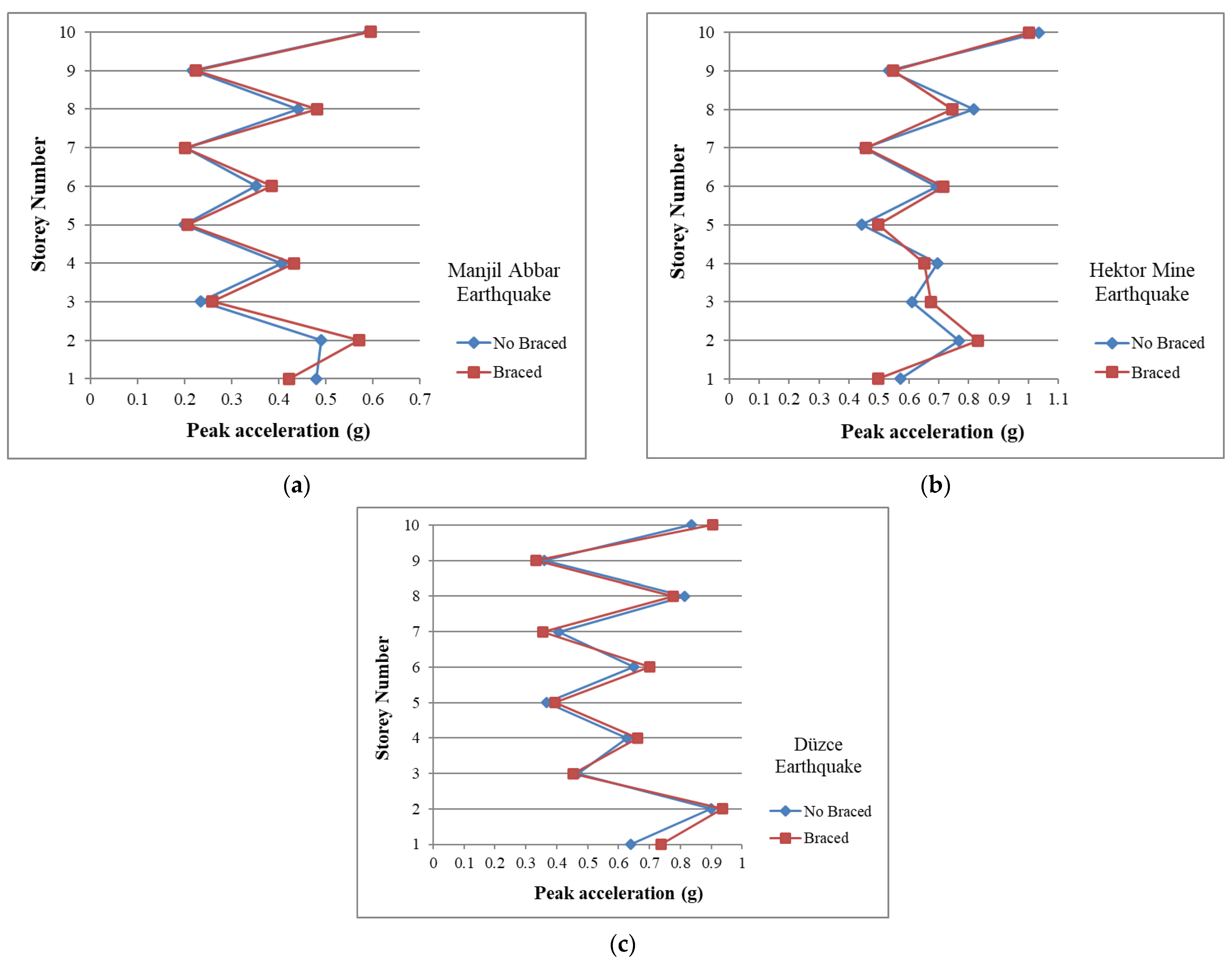
After the selected earthquake data were transported to the surface, it was applied to the scaled 10-story steel structure with and without bracing with the help of scaled shake table experiments. Based on Figure 11, the variation in the peak acceleration of each earthquake for the story is determined and analyzed with and without bracing.
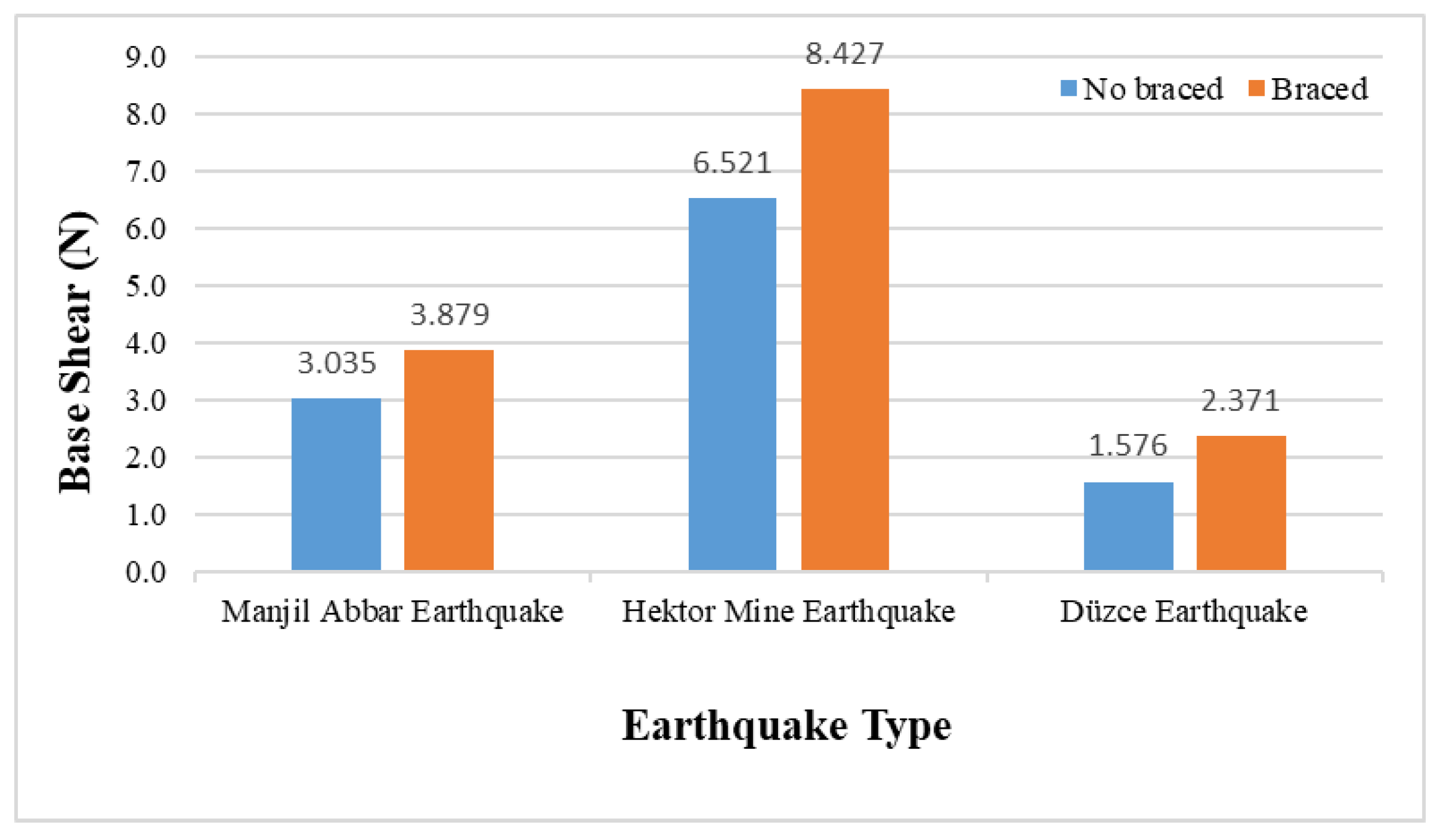
As seen in detail in Table 6, in the Manjil Abbar Earthquake, the braced system increased the base shear force by 27.82% compared to the unbraced system; in the Hektor Mine Earthquake, the braced system increased the base shear force by 29.23% compared to the unbraced system, and in the Düzce Earthquake, the braced system increased the base shear force by 50.46% compared to the unbraced system. As shown in Figure 12, it was determined that the braced system increased the base shear force compared to the unbraced system in all three earthquakes.
The soil conditions and design conditions of the structure will affect the performance of the structure. The shear force at the base of a structure is affected by the properties of the bracings used, the mass of the structure, and the soil conditions in which the structure will be built [13]. In addition, the change in the base shear force in the structure is a very important parameter in the kinematic interaction analysis and the design phase. As a result, although the use of X steel diagonal bracing systems seems sufficient in terms of structural design, in terms of earthquake-resistant building reinforcement, it can negatively affect foundation designs because it increases base shear forces in terms of structure–soil interaction. For this reason, when evaluating the use of X steel diagonal bracing systems in terms of building design resistant to possible earthquake scenarios, attention should be paid to designing these systems by taking the SSI into consideration, and reinforcement scenarios should not be evaluated only in terms of structural reinforcement.
In Table 7, the moment and shear forces of a 10-story, single-span steel structure at different pile lengths, different inter-pile distances, and under three different earthquake forces are analyzed using the data obtained numerically in the unbraced and braced cases. In the Manjil Abbar Earthquake, when the distance between the piles was s/d = 0.167 m and the pile length increased from 0.8 m to 2.4 m, a 29.29% increase in bending moment and a 40.67% increase in shear force were observed for the unbraced case. In the Hektor Mine Earthquake, a 72.08% increase in bending moment and a 76.16% increase in shear force were observed for the unbraced case, and in the Düzce Earthquake, a 65.91% increase in bending moment and a 78.18% increase in shear force were observed for the unbraced case. When these changes are evaluated for the braced case based on all earthquakes, remarkable changes are not observed when compared to the unbraced case. This situation may be caused by kinematic interaction effects. For this condition, kinematic interaction effects are more dominant than inertial interaction effects on the pile raft system. Therefore, the change in the braced system of the structure does not directly affect the pile raft system very much. On the other hand, at different earthquake effects, the design parameters of the piles showed variability. The main reason for this situation can be explained, and the characterizations and behaviors of the earthquakes used in this study are different from each other. The accelerations, velocities, frequencies, and duration of the earthquakes used in this study are different from each other. For this reason, the effects of the earthquakes vary in a wide range.
Similarly, when the distance between piles was increased by s/d, increases in bending moment and shear forces were observed under different earthquake forces. In the Manjil Abbar Earthquake, when the distance between piles was s/d = 0.260 m and the pile length was increased from 0.8 m to 2.4 m, a 31.17% increase in bending moment and a 40.38% increase in shear force were observed for the unbraced case. In the Hektor Mine Earthquake, a 71.76% increase in bending moment and a 75.73% increase in shear force were observed for the unbraced case, and in the Düzce Earthquake, a 65.42% increase in bending moment and a 77.87% increase in shear force were observed for the unbraced case. When these changes are evaluated for the braced case based on all earthquakes, remarkable changes are not observed when compared to the unbraced case. This situation may be caused by kinematic interaction effects. For this condition, kinematic interaction effects are more dominant than inertial interaction effects on the pile raft system. Therefore, the change in braced system of the structure does not directly affect the pile raft system very much. On the other hand, at different earthquake effects, the design parameters of the piles showed variability. The main reason for this situation can be explained, and the characterizations and behaviors of the earthquakes used in this study are different from each other. The accelerations, velocities, frequencies, and duration of the earthquakes used in this study are different from each other. For this reason, the effects of the earthquakes vary in a wide range. When s/d ratio effects are evaluated, the increase in the s/d ratio with respect to the length of the piles does not have considerable effects on the pile design parameters. This can be explained as the damping ratio effect of the soil profile on absorbing earthquake effects under kinematic interaction conditions. In other words, the soil profile may absorb more earthquake energy for this case condition.
In this study, a three-layered soil profile was defined. Therefore, when the length of the pile increases, the small part of the piles is embedded to the other soil profile, as it is commonly known that the kinematic interactions increase with the increase in the number of soil profiles in which piles are embedded [46]. A similar behavior was also observed in this study. When pile length increased, the design parameters of the piles also increased for all conditions defined in this study.

4. Conclusions

The conclusions that were concluded from this study are given as follows:
  • The soil conditions and design conditions of the structure will affect the performance of the structure. The shear force at the base of a structure is affected by the properties of the bracings used, the mass of the structure, and the soil conditions in which the structure will be built [13]. In addition, the change in the base shear force in the structure is a very important parameter in the kinematic interaction analysis and the design phase. As a result, although the use of X steel diagonal bracing systems seems sufficient in terms of structural design, in terms of earthquake-resistant building reinforcement, it can negatively affect foundation designs because it increases base shear forces in terms of structure–soil interaction;
  • Kinematic interaction effects are more dominant than inertial interaction effects on the pile raft system. Therefore, the change in the braced system of the structure does not directly affect the pile raft system very much. On the other hand, at different earthquake effects, the design parameters of the piles showed variability. The main reason for this situation can be explained, and the characterizations and behaviors of the earthquakes used in this study are different from each other. The accelerations, velocities, frequencies, and duration of the earthquakes used in this study are different from each other. For this reason, the effects of the earthquakes vary in a wide range;
  • Similarly, when the distance between piles was increased by s/d, increases in bending moment and shear forces were observed under different earthquake forces. When s/d ratio effects are evaluated, the increase in the s/d ratio with respect to the length of the piles does not have considerable effects on the pile design parameters. This can be explained as the damping ratio effect of the soil profile on absorbing earthquake effects under kinematic interaction conditions. In other words, the soil profile may absorb more earthquake energy for this case condition;
  • In this study, a three-layered soil profile was defined. Therefore, when the length of the pile increases, the small part of the piles is embedded to the other soil profile, as it is commonly known that the kinematic interactions increase with the increase in the number of soil profiles in which piles are embedded [46]. A similar behavior was also observed in this study. While pile length increased, the design parameters of the piles also increased for all conditions defined in this study.

Author Contributions

Conceptualization, S.T., F.C. and E.A.; Methodology, F.C. and E.A.; Software, S.T.; Validation, S.T. and E.A.; Investigation, S.T.; Resources, S.T.; Writing – original draft, S.T. and F.C.; Writing—review & editing, E.A.; Visualization, F.C.; Supervision, F.C. All authors have read and agreed to the published version of the manuscript.

Funding

This research received no external funding.

Data Availability Statement

The original contributions presented in the study are included in the article, further inquiries can be directed to the corresponding author.

Conflicts of Interest

The authors declare no conflict of interest.

References

  1. Siyahi, B.; Çetin, K.Ö.; Bilge, H.T. A critical view on soil-foundation-structure interaction from the perspective of geotechnical earthquake engineering. Turk. Eng. News 2013, 484, 41–50. [Google Scholar]
  2. EN 1998-5; Eurocode 8: Design of Structures for Earthquake Resistance–Part 5: Foundations, Retaining Structures and Geotechnical Aspects. European Union: Brussels, Belgium, 2003.
  3. FEMA 440; Improvement of Nonlinear Static Seismic Analysis Procedures. Federal Emergency Management Agency: Washington, DC, USA, 2005.
  4. Kawashima, K.; Unjoh, S. Specification for Highway Bridges: Seismic Design; Japanese Road Association: Tokyo, Japan, 1996. [Google Scholar]
  5. Ghosh, B.; Lubkowski, Z. Modelling dynamic soil structure interaction under seismic loads. In Design of Foundations in Seismic Areas: Principles and Applications; Bhattacharya, S., Ed.; NICEE, IIT Kanpur: Kanpur, Indiam, 2007; pp. 118–198. [Google Scholar]
  6. Meymand, P.J. Shaking Table Scale Model Tests of Nonlinear Soil-Pile Superstructure Interaction in Soft Clay. Ph.D. Dissertation, University of California, Berkeley, CA, USA, 1998. [Google Scholar]
  7. Mylonakis, G.; Gazetas, G. Seismic soil-structure interaction: Beneficial or detrimental? J. Earthq. Eng. 2000, 4, 277–301. [Google Scholar] [CrossRef]
  8. Kaynia, M.A.; Mahzoon, P.S. Forces in pile foundations under seismic loading. J. Eng. Mech. 1996, 122, 46–53. [Google Scholar] [CrossRef]
  9. Nogami, T.; Novak, M. Soil-pile interaction in vertical vibration. Earthq. Eng. Struct. Dyn. 1976, 4, 277–294. [Google Scholar] [CrossRef]
  10. Novak, M. Dynamic stiffness and damping of piles. Can. Geotech. J. 1974, 11, 574–598. [Google Scholar] [CrossRef]
  11. Wolf, J. Dynamic Soil-Structure Interaction; Prentice Hall, Inc.: Hoboken, NJ, USA, 1985. [Google Scholar]
  12. Moncarz, P.; Krawinkler, H. Theory and Application of Experimental Model Analysis in Earthquake Engineering; Rep. No. 50; John, A., Ed.; Stanford University: Stanford, CA, USA, 1981. [Google Scholar]
  13. Nassani, D.E.; Hussein, A.K.; Mohammed, A.H. Comparative response assessment of steel frames with different bracing systems under seismic effect. In Structures; Elsevier: Amsterdam, The Netherlands, 2017; Volume 11, pp. 229–242. [Google Scholar]
  14. Moghaddam, H.; Hajirasouliha, I. An investigation on the accuracy of pushover analysis for estimating the seismic deformation of braced steel frames. Constr. Steel Res. 2006, 62, 343–351. [Google Scholar] [CrossRef]
  15. Asgarian, B.; Moradi, S. Seismic response of steel braced frames with shape memory alloy braces. Constr. Steel Res. 2011, 67, 65–74. [Google Scholar] [CrossRef]
  16. Tremblay, R. Inelastic seismic response of steel bracing members. J. Constr. Steel Res. 2002, 58, 665–701. [Google Scholar] [CrossRef]
  17. Bharmal, P.P.; Kumbhar, P.D.; Gumaste, K.S. Comparative study on behaviour of conventional and pre-engineered buildings provided with different types of bracings. Asian J. Civ. Eng. 2024, 25, 451–459. [Google Scholar] [CrossRef]
  18. Bouderradji, M. Seismic performance assessment of deficient RC structures retrofitted with different steel bracing systems. J. Eng. Exact Sci. 2023, 9, 16884-01e. [Google Scholar] [CrossRef]
  19. Liu, X.; Zhou, X.; Zhang, A.; Tian, C.; Zhang, X.; Tan, Y. Design and compilation of specifications for a modular-prefabricated high-rise steel frame structure with diagonal braces. Part I: Integral structural designd. Struct. Des. Tall Spec. Build. 2017, 27, e1415. [Google Scholar] [CrossRef]
  20. Roshan, P.; Meena, R.K.; Singh, I. Analyzing the effectiveness of bracing patterns in high-rise buildings. In Hydraulic and Civil Engineering Technology VIII; IOS Press: Amsterdam, The Netherlands, 2023. [Google Scholar] [CrossRef]
  21. Qiu, C.; Zhu, S. Shake table test and numerical study of self-centering steel frame with SMA braces. Earthq. Eng. Struct. Dyn. 2016, 46, 117–137. [Google Scholar] [CrossRef]
  22. Erochko, J.; Christopoulos, C.; Tremblay, R.; Kim, H. Shake table testing and numerical simulation of a self-centering energy dissipative braced frame. Earthq. Eng. Struct. Dyn. 2013, 42, 1617–1635. [Google Scholar] [CrossRef]
  23. Goggins, J.; Jiang, Y.; Broderick, B.; Salawdeh, S.; O’Reilly, G.; Elghazouli, A.; Markovski, I. Shake table testing of self-centering concentrically braced frames. Ce/Papers 2021, 4, 1949–1956. [Google Scholar] [CrossRef]
  24. Aydin, E.; Boduroglu, M.H. Optimal placement of steel diagonal braces for upgrading the seismic capacity of existing structures and its comparison with optimal dampers. J. Constr. Steel Res. 2008, 64, 72–86. [Google Scholar] [CrossRef]
  25. Anoyatis, G.; Laora, R.; Mandolini, A.; Mylonakis, G. Kinematic response of single piles for different boundary conditions: Analytical solutions and normalization schemes. Soil Dyn. Earthq. Eng. 2013, 44, 183–195. [Google Scholar] [CrossRef]
  26. Maugeri, M.; Motta, E.; Raciti, E.; Ardita, D. Kinematic interaction of a single pile in heterogeneous soil. WIT Trans. Built Environ. 2009, 104, 95–104. [Google Scholar] [CrossRef]
  27. Garala, T.; Madabhushi, G. Influence of phase difference between kinematic and inertial loads on seismic behavior of pile foundations in layered soils. Can. Geotech. J. 2021, 58, 1005–1022. [Google Scholar] [CrossRef]
  28. Chidichimo, A.; Cairo, R.; Dente, G.; Taylor, C.; Mylonakis, G. 1-g Experimental investigation of bi-layer soil response and kinematic pile bending. Soil Dyn. Earthq. Eng. 2014, 67, 219–232. [Google Scholar] [CrossRef]
  29. Aldimashki, M.; Brownjohn, J.; Bhattacharya, S. Experimental and Analytical Study of Seismic Soil-Pile-Structure Interaction in Layered Soil Half-Space. J. Earthq. Eng. 2014, 18, 655–673. [Google Scholar] [CrossRef]
  30. Padrón, L.; Aznárez, J.; Maeso, O. Dynamic analysis of piled foundations in stratified soils by a BEM-FEM model. Soil Dyn. Earthq. Eng. 2008, 28, 333–346. [Google Scholar] [CrossRef]
  31. Li, Z.; Escoffier, S.; Kotronis, P. Centrifuge modeling of batter pile foundations under sinusoidal dynamic excitation. Bull. Earthq. Eng. 2016, 14, 673–697. [Google Scholar] [CrossRef]
  32. Hokmabadi, A.S.; Fatahi, B.; Samali, B. Physical modeling of seismic soil-pile-structure interaction for buildings on soft soils. Int. J. Geomech. 2015, 15, 04014046. [Google Scholar] [CrossRef]
  33. Hashash, Y.M.A.; Musgrove, M.I.; Harmon, J.A.; Groholski, D.R.; Phillips, C.A.; Park, D. DEEPSOIL 6.1, User Manual; Board of Trustees of University of Illinois at Urbana-Champaign: Urbana, IL, USA, 2016. [Google Scholar]
  34. Al Atik, L.; Abrahamson, N. An improved method for nonstationary spectral matching. Earthq. Spectra 2010, 26, 601–617. [Google Scholar] [CrossRef]
  35. SeismoMatch. Earthquake Software for Response Spectrum Matching; Seismosoft: Pavia, Italy, 2020. [Google Scholar]
  36. Ozbulut, O.; Hurlebaus, S.; DesRoches, R. Seismic response control using shape memory alloys: A review. J. Intell. Mater. Syst. Struct. 2011, 22, 1531–1549. [Google Scholar] [CrossRef]
  37. Araki, Y.; Shrestha, K.; Maekawa, N.; Koetaka, Y.; Omori, T.; Kainuma, R. Shaking table tests of steel frame with superelastic cu–al–mn sma tension braces. Earthq. Eng. Struct. Dyn. 2015, 45, 297–314. [Google Scholar] [CrossRef]
  38. Subramanya, K.G.; Govindaraju, L.; Babu, R.R. Shake Table Studies on the Dynamic Response of Pile Supported Framed Structure in Soft Soil. Civ. Eng. Archit. 2020, 8, 1313–1324. [Google Scholar]
  39. Chopra, A.K. Dynamics of Structures: Theory and Applications to Earthquake Engineering, 4th ed.; Prentice Hall: Englewood Cliffs, NJ, USA, 2012. [Google Scholar]
  40. Tao, X.; Kagawa, T.; Minowa, C.; Abe, A. Verification of dynamic soil-pile interaction. In Geotechnical Earthquake Engineering and Soil Dynamics, 3rd ed.; ASCE: New York, NY, USA, 1998; pp. 1199–1210. [Google Scholar]
  41. Bao, Y.; Ye, G.; Ye, B.; Zhang, F. Seismic evaluation of soil–foundation–superstructure system considering geometry and material nonlinearities of both soils and structures. Soils Found. 2012, 52, 257–278. [Google Scholar] [CrossRef]
  42. Chau, K.T.; Shen, C.Y.; Guo, X. Nonlinear seismic soil-pile structure interactions: Shaking table tests and FEM analyses. Soil. Dyn. Earthq. Eng. 2009, 29, 300–310. [Google Scholar] [CrossRef]
  43. Reese, L.C.; Cox, W.R.; Koop, F.D. Analysis of laterally loaded piles in sand. In Proceedings of the 6th Annual Offshore Technology Conference, Houston, TX, USA, 6–8 May 1974; Volume 2, pp. 473–485. [Google Scholar]
  44. Nghiem, H. Soil-Pile-Structure Interaction Effects on High Rises Under Seismic Shaking. Ph.D. Thesis, University of Colorado, Denver, CO, USA, 2009. [Google Scholar]
  45. Mendoza, M.; Romo, M. Behavior of building foundations in Mexico City during the 1985 Earthquake: Second stage. In Lessons Learned from the 1985 Mexico Earthquake; Earthquake Engineering Research Institute: El Cerrito, CA, USA, 1989; pp. 66–70. [Google Scholar]
  46. Yiğit, M.A.; Onur, M.İ.; Balaban, E. Investigation of soil pile interaction parameters in piled foundations. J. Fac. Eng. Archit. Gazi Univ. 2022, 37, 625–639. [Google Scholar]
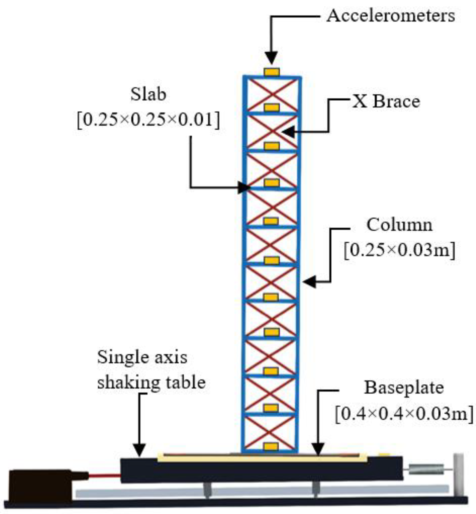
Figure 1. Single-axis shaking table.
Buildings 15 00764 g001
Figure 2. East–West response spectrum of 3 different earthquake records scaled to the design spectrum: (a) not matched and (b) matched.
Buildings 15 00764 g002
Figure 3. Adopted shaking events in this study: (a) no scaled and scaled Manjil Abbar Earthquakes; (b) no scaled and scaled Hektor Mine Earthquakes; (c) no scaled and scaled Düzce Earthquakes.
Buildings 15 00764 g003
Figure 4. Model structure for shaking table experiments.
Buildings 15 00764 g004
Figure 5. Peak acceleration–frequency graph of floors under harmonic load.
Buildings 15 00764 g005
Figure 6. Steel building frame and structure response.
Buildings 15 00764 g006
Figure 7. Calculated p–y curves for the scaled soil model: (a) variation in p–y values of SM soil with depth; (b) variation in p–y values of SW soil with depth.
Buildings 15 00764 g007
Figure 8. Maximum displacements along the depth for the different earthquake data. (a) Maximum displacements of real soil. (b) Maximum displacements of scaled soil.
Buildings 15 00764 g008
Figure 9. Variation in peak ground acceleration with depth for 3 different earthquakes. (a) Variation in peak acceleration for real soil (b) Variation in peak acceleration for scaled soil.
Buildings 15 00764 g009
Figure 10. Variation in the ideal soil profile with depth according to different earthquake data: (a) real soil and (b) scaled Soil.
Buildings 15 00764 g010
Figure 11. Peak accelerations with and without braces according to the story: (a) Manjil Abbar Earthquake; (b) Hektor Mine Earthquake; (c) Düzce Earthquake.
Buildings 15 00764 g011
Figure 12. Effect of base shear for no braced and braced frames under different earthquakes.
Buildings 15 00764 g012
Table 1. Scaling relationships in terms of the geometric scaling factor (λ) [6].
ParameterScaling Relationship
Mass density1
Forceλ3
Stiffnessλ2
Modulusλ
Acceleration1
Shear-wave velocityλ1/2
Timeλ1/2
Frequencyλ−1/2
Lengthλ
Stressλ
Strain1
EIλ5
Table 2. Earthquake-based motions used.
EarthquakeYearPeak Ground Acceleration PGA (g)Magnitude (R)Duration
(s)
Hypo Central Distance (km)
Manjil Abbar19900.2157.3745.312.55
Hektor Mine19980.2967.1353.511.66
Düzce19990.1907.1430.004.21
Table 3. Characteristics of the soil profile.
Soil PropertiesSymbolUnit1.
Layer (SM)
2.
Layer (SW)
3.
Layer (GM-SM)
RockPeriod Frequency
T (s)f (Hz)
Real SoilLayer thicknesshm303030-1.3330.75
Mass densityρkg/m31600180020002200
Shear wave
velocity
Vsm/s150350630760
CohesionckPa605512-
Modulus of
Elasticity
EkN/m2500025,0005 × 106-
Poisson Ratiov-0.420.380.25-
Shear strength angleφ°28°23°-
Model (to scale) SoilLayer thicknesshm222-0.3442.904
Mass densityρkg/m31600180020002200
Shear wave
velocity
Vsm/s38.7390.37162.66196.21
CohesionckPa605512-
Modulus of
Elasticity
EkN/m2500025,0005 × 106-
Poisson Ratiov-0.420.380.25-
Shear strength angleφ°28°23°-
Table 4. Pile characteristics of the real pile and model (to scale) pile.
Pile PropertiesSymbolUnitReal PileModel (to Scale) Pile
DiameterDm0.80.053
LengthLm120.8
362.4
Moment of inertiaIm40.023.87 × 10−7
Flexural rigidityEkN/m232 × 1062170.5
Table 5. Distance between real piles and model (to scale) piles.
Distance Between Piles and Pile Length
Real PileScaled Pile
S/D = 2.5 mS/D = 4 m S/D = 0.167 mS/D = 0.26 m
Buildings 15 00764 i001Buildings 15 00764 i002Buildings 15 00764 i003Buildings 15 00764 i004Buildings 15 00764 i005Buildings 15 00764 i006
Table 6. Change in the base shear force with no braced and braced for different earthquakes.
Manjil Abbar
Earthquake
Base Shear (kN)
Hektor Mine
Earthquake
Base Shear (kN)
Düzce
Earthquake
Base Shear (kN)
No braced3.0356.5211.576
Braced3.8798.4272.371
Table 7. No braced and braced pile shear force (M), bending moment (V), and displacement (D) values calculated for the system under dynamic loads.
No BracedBraced
Pile Spacing
(m)
EarthquakesPile Length (m)M
(Nm)
V
(N)
D
(mm)
M
(Nm)
V
(N)
D
(mm)
s/d = 0.167Manjil Abbar0.811.7183.156.69811.8083.476.698
2.416.56140.146.73516.65140.466.736
29.29%40.67%0.55%29.13%40.57%0.56%
Hektor Mine0.815.31110.487.33615.51111.207.337
2.454.83463.467.47355.03464.177.475
72.08%76.16%1.83%71.82%76.04%1.85%
Düzce0.88.8870.604.7648.9770.904.764
2.426.05323.594.83226.13323.894.833
65.91%78.18%1.41%65.67%78.11%1.43%
s/d = 0.26Manjil Abbar0.811.8884.156.69611.9784.476.696
2.417.26141.146.72217.35141.466.723
31.17%40.38%0.39%31.01%40.29%0.40%
Hektor Mine0.815.51112.477.33315.71113.207.334
2.454.93463.457.45655.13464.177.457
71.76%75.73%1.65%71.50%75.61%1.65%
Düzce0.89.0171.604.7629.0971.904.762
2.426.05323.594.82026.14323.894.823
65.42%77.87%1.20%65.23%77.80%1.26%
Disclaimer/Publisher’s Note: The statements, opinions and data contained in all publications are solely those of the individual author(s) and contributor(s) and not of MDPI and/or the editor(s). MDPI and/or the editor(s) disclaim responsibility for any injury to people or property resulting from any ideas, methods, instructions or products referred to in the content.