Abstract
The article presents the results of an experimental study on driven reinforced concrete piles with hybrid shaft, which incorporates several wedge-shaped elements with inclined side faces. A technology for the installing of these piles, involving the addition of loose materials to enhance soil compaction, is herein proposed. Field experiments were conducted to determine the energy intensity of driving and the uplift load resistance of these piles. It was found that the energy intensity of a driving hybrid pile with loose materials addition is 1.4–3.5 times greater compared to conventional driven piles. However, the uplift bearing capacity was 1.5–4.4 times higher than that of piles with a traditional shape. The efficiency of the experimental piles is attributed to an increase in the volume of wedge-shaped elements on the pile shaft and the incorporation of loose materials, such as gravel and sand. The uplift capacity of hybrid shaft piles improves with the increasing volume of the aforementioned parameters. The obtained correlation dependencies enable a reliable calculation of the energy intensity and uplift resistance of hybrid shaft piles installed with the addition of loose materials. These findings hold significant practical importance for foundation design using piles with non-traditional shaft shapes in variant design assessments.
1. Introduction
It is known that the pile foundations of various structures (e.g., hydraulic structures, wind power plants, and berthing structures) operate under uplift load conditions [1,2,3,4]. The resistance of piles to uplift loads must also be considered when constructing foundations in swelling soils or soils subject to frost heaving [5,6]. Additionally, mandatory consideration of uplift loads is required in the design of mast structures, such as power transmission lines, television towers, floodlight masts, cellular repeaters, lighthouses, and flagpoles [7]. The significant height and small bearing area of these structures, combined with the large wind loads acting upon them, necessitate ensuring their resistance to uplift loads and stability against overturning.
To ensure the resistance of pile foundations to uplift loads, various approaches are employed. One such approach involves using piles with non-standard shaft shapes, including extensions, thickenings, grooves, telescopic forms, or roughened surfaces [8,9,10,11,12,13]. These shaft modifications improve the clamping of the pile by the surrounding soil, thereby increasing uplift resistance. The use of such piles has been shown to increase bearing capacity by 1.1–3.88 times compared to conventional prismatic piles [14]. It should be noted that pile resistance depends not only on the design features but also on the type and condition of the soil as well as on the shape and size of the shaft elements.
The efficiency of using piles with non-conventional shaft shapes has been confirmed by various studies. For instance, the positive effect of pile widening on the increase in uplift resistance was demonstrated in ref. [15]. The study examined reinforced concrete piles with bell-shaped widenings:
- -
- Piles with one widening (heel): shaft diameter D = 1.0 m, widening diameter—d = 1.6 m, and shaft length L = 21.0 m;
- -
- Piles with two widenings: D = 1.0 m, d = 1.4 m, and L = 8.0 m.
The piles were embedded in sandy soil. The greatest displacement of piles during pulling out, equal to 31 cm, was achieved under an uplift load of 14,715 kN. The tests showed high resistance to pulling out for piles with two widenings. According to the authors, this was due to the increased friction forces along the larger contact surface compared to piles with a single widening.
Similar results were obtained when testing piles with varying cross-sectional dimensions. These tests, also conducted in sandy soil [16], involved piles with diameters of 0.35 m, 0.4 m, and 0.5 m and an embedment depth of 10 m. The ultimate resistance of the piles to the uplift load reached 387 kN, 440 kN, and 478 kN, respectively, when the piles were displaced by 25 mm. The mobilization of friction forces along the pile surface (21–45 kPa) began at a displacement of approximately 5 mm. The results demonstrated that the greater the contact area between the pile’s lateral surface and the surrounding soil, the higher its resistance to uplift loads.
The bell-shaped form at the lower end of piles significantly increases their bearing capacity in sandstones [17]. In experiments, 6.0 m and 7.0 m long piles with shaft diameters of d = 0.8 m and widening diameters of du =1.2 m were tested. The share of the widening in the total bearing capacity reached 55% and 35%, respectively. It was observed that as the load share supported by the widening increased, the contribution of frictional resistance along the shaft without the widening decreased. Additionally, increasing pile length improved uplift resistance due to better soil clamping; however, the relative effect of the widening diminished with increasing length.
The effect of pile widening on uplift resistance in clay soils was assessed in ref. [18]. Comparative tests were conducted on a pile with a bell-shaped widening at its lower end and a conventional pile without widening. The widened pile exhibited significantly higher bearing capacity during pulling out. Furthermore, the results indicated that the inclination angle of the widening face significantly influenced its effectiveness. The maximum increase in bearing capacity, by 100% and 180%, was achieved with inclination angles of 35° and 40°, respectively, relative to the pile axis.
Laboratory and field tests further confirmed the effectiveness of broadened piles in resisting uplift forces [19]. Experiments with driven pile models featuring flat pyramidal broadenings demonstrated resistance 1.25–3.25 times higher than conventional prismatic or pyramidal piles in laboratory conditions. Field tests yielded similar results, with uplift resistance exceeding that of conventional piles by 1.17–2.42 times. It was also found that uplift resistance increased with the number of broadenings on the pile shaft. The highest uplift capacity was observed for piles with three or four pyramidal broadenings.
The effect of pile shaft surface roughness on the growth of bearing capacity was revealed by the results of laboratory pull-out tests of short piles in homogeneous sand [20]. Piles with a diameter of 12.7 mm, having both smooth and rough surface, were pulled out from dry and soaked sand of loose and compacted composition. From the experimental results, it follows that the pile resistance to uplift load increases with an increase in the following factors:
- -
- The ratio of the pile length to shaft diameter;
- -
- The roughness of the pile shaft surface;
- -
- The size of sand particles and the degree of their compaction.
It was found that the friction forces on the lateral surface of piles during pull-out appear to a lesser extent than during their pressing in. Moreover, this difference depends on the condition of the piles’ lateral surface. For smooth-surfaced piles, the mobilization of friction forces reaches 10–50%, while for piles with rough surface, it was up to 80%. The maximum uplift bearing capacity of a pile in loose sand occurred when it was moved about 40 mm (5% of the pile diameter), while in dense sand, this occurred at around 80 mm (10% of the pile diameter). It was also found that the pressure acting on the pile decreases in dense sand but not in loose sand.
The mutual influence of the geometric parameters of concrete pile models in compacted sandy soil, and their uplift resistance is considered in ref. [21]. The diameters of the pile models were 20 mm, 30 mm, and 40 mm, and the shaft lengths were 0.2 m, 0.3 m, and 0.4 m (for each model, the piles had different diameters). It was found that the resistance of the pile models was higher with larger dimensions. Based on the experimental data, a correlation was obtained between the geometric parameters of the pile models and their resistance to pull-out.
The study [22] presents the results of testing a full-scale pile (D = 0.8 m and L = 22.0 m) under pull-out loads. After testing, the pile was checked for cracks and the localization of concrete deformations. It was found that with an increase in pile installation depth, resistance to uplift loads also increased. For example, deepening the pile from 11–18 m to 18–21.5 m caused an increase in the pull-out load from 5060 kN to 6240 kN. Compared with the control pile (with conventional reinforcement), the experimental pile (with composite reinforcement) demonstrated 88.2% higher resistance to concrete cracking and 48.3% lower localization of crack formation.
Experiments on pulling out reinforced concrete piles with shells reinforced by fiberglass and basalt fibers, carried out under field conditions [23], showed that their uplift resistance increased by 15.56% (68.64 kN) and 35.56% (80.52 kN), respectively, compared to a control pile without the use of fibers. According to the authors, the reason for this is the increase in the angle of interphase friction between the shaft and the surrounding soil. The authors also saw the potential for further increasing the resistance of piles to uplift load through the creation of protrusions (bulges) at different heights along their shaft.
The effect of the profiled surface of the pile on increasing its bearing capacity was described in ref. [24]. A model of a tubular pile with round through-holes, perpendicular in plan along the shaft, was tested in highly moistened clay soil. This permeable pile was designed to simultaneously perform bearing and drainage functions, i.e., to remove excess pore water from the surrounding soil. Mathematical modeling established an increase in the bearing capacity of the pile due to the phenomenon of accelerated rheological consolidation of the soil. Using semi-analytical methods, the displacement of the pile and the soil was assessed at elastic, transitional, and plastic stages of deformation. A comparative assessment of the results of numerical modeling with previously conducted laboratory experiments was performed. Based on these, the effect of soil viscosity on the pile displacement was established, and the influence of the profiled surface of the pile on its resistance to loads was determined.
Using the discrete elements method, the performance of GRPS piles as part of embankments was analyzed, revealing an increase in their bearing capacity in soft soils [25]. Modeling the operation of GRPS piles (in combination with geosynthetic reinforcement) as the foundation of an embankment demonstrated a reduction in soil slippage and an increase in its bearing capacity. The modeling also showed that the piles effectively distribute the applied load across the embankment, resulting in reduced differential settlement of the soil. According to the authors, a further decrease in embankment soil settlement—by up to 50%—can be achieved by increasing the height of the geosynthetic reinforcement used as the pile grillage.
The use of piles in the foundation of an embankment made of sand and gravel soils ensured the redistribution of embankment loads through shearing and reducing effects on the soil [26]. The mechanisms and factors behind this phenomenon were explained by the authors through the concepts of arching or bending of the soil, transferring stresses from the embankment to the soil through the pile. In this case, the redistribution of pressure from the soil to the pile was higher when the width and length of the pile were greater. These findings correlate well with the influence of pile shape features (such as the presence of widenings) and the increase in resistance to lateral friction, which collectively enhance the bearing capacity of the pile.
An analysis of the results from the existing studies shows that the design parameters and features of piles (type of reinforcement, embedment depth, cross-sectional dimensions, length, presence of widenings, and their number) positively affect the resistance of piles to uplift loads. At the same time, the role of widening elements in increasing the bearing capacity of pile shafts is particularly significant.
Considering the high efficiency of non-standard shaped piles under uplift loads, the authors of the present study developed new piles with a hybrid shaft design. A distinctive feature of these piles is the presence of several widening elements of the shaft, shaped as truncated flat prisms. Despite the addition of these widening elements, the overall volume of the pile remains unchanged relative to a prismatic pile with a cross-section of 30 × 30 cm. This is achieved by reducing the cross-sectional dimensions of the pile shaft. Previously conducted studies [13,27,28] demonstrated the significant bearing capacity of these piles due to their better interaction with the soil mass. Due to the presence of additional shaft elements with inclined edges, the bearing capacity hybrid shaft piles under uplift loads was found to be 1.17–2.42 times higher than that of traditional-shape piles. These studies also highlighted the potential for further improvement in their resistance through enhanced driving technology.
The proposed improvement in driving technology involves introducing an additional volume of rigid or loose material into the space between the pile and the surrounding soil during the installation of these new piles. According to our assumptions, the addition of loose material will further increase the resistance of hybrid shaft piles to uplift loads. It is expected that the introduced loose material will penetrate and fill the space between the pile and the surrounding soil due to impact pulses. As the pile penetrates deeper, a larger volume of loose material will be introduced into the soil along with the pile, thereby creating a compacted soil core around the pile. Compacted soil, as is well known, compresses the pile shaft more effectively, providing stronger clamping. Achieving this effect ultimately ensures increased uplift resistance, which is the subject of the present research.
This assumption is supported by several factors explaining the operating principle of hybrid shaft piles using the proposed driving technology. During installation, the wedge-shaped elements of the pile with inclined edges not only experience frictional forces from the soil but also the rebound forces, the combined effect of which reduces pile displacement. When the slots between the lower and upper wedge-shaped elements of the shaft are additionally filled with bulk material, the frictional and rebound forces are further amplified. Moreover, this phenomenon occurs at the boundary conditions of two systems: the pile, i.e., surrounding soil and pile, and the backfill (bulk material), i.e., the surrounding soil. At the boundary of each system, frictional forces along the lateral surface and soil rebound forces from the thrust effect of the wedge-shaped elements arise, collectively increasing resistance.
The mentioned driving technology demonstrated its positive effects during comparative tests of pile models under axial static load in laboratory conditions. The addition of loose materials during the driving of pile models was found to increase their bearing capacity by 1.15–1.68 times [28].
The technology of increasing the bearing capacity of foundations using loose rigid materials (crushed stone, gravel, dry cement-sand mixture, concrete mortar, etc.) has been widely applied in stamping pits, constructing strip foundations, and similar applications. Inert material introduced during foundation compaction creates a compacted soil core. Foundations constructed on such bases exhibit significantly higher resistance and bearing capacity—by 2.0–2.4 times [29]. The application of this technology also reduces the consumption of reinforced concrete, resulting in a cost reduction for foundation works in construction.
Considering the positive effects of the mentioned studies, the authors of this work conducted research to study the resistance of piles with a hybrid shaft to uplift loads, with the addition of loose materials during pile driving. Sand and gravel, which are most commonly used in construction and characterized by sufficient flowability, were adopted as loose materials. Given the lack of experimental data on the uplift bearing capacity of piles with a hybrid shaft in general as well as the specific features of resistance changes due to the addition of loose materials, comparative tests were carried out under field conditions.
The results of this research contribute to the accumulation of experimental data on the uplift resistance features of piles with a hybrid shaft. These data will enable the development of a technology for driving piles with a hybrid shaft and the addition of loose materials to ensure their resistance to uplift load effects.
Thereby, the distinctive features of this study compared to previous research are the following aspects, which determine its novelty and the value of the obtained results:
- -
- The object of the study is driven reinforced concrete piles with a hybrid shaft, featuring several widened elements with inclined side faces. The design novelty of these piles, including their geometric shapes, sizes, and the number of widenings, along with the lack of experimental data on their behavior during driving and resistance to loads, necessitates experimental research to establish the main parameters of their operation;
- -
- The technology of driving hybrid shaft piles using loose materials, such as sand and gravel, with metered introduction during driving, ensures increased resistance of piles to applied loads;
- -
- Establishing the optimal parameters for driving hybrid shaft piles, including driving energy intensity, uplift resistance, and bearing capacity, will facilitate the preparation of recommendations for the practical use of hybrid shaft piles in construction practice.
2. Materials and Methods
A pile with a hybrid shaft comprises structural elements with different shapes, combined into a single whole:
- -
- A tip, which has a flat prismatic shape;
- -
- Wedge-shaped elements on both sides of the shaft, which have flat prismatic shapes;
- -
- A pile head, which has the shape of a classic prism (Figure 1).
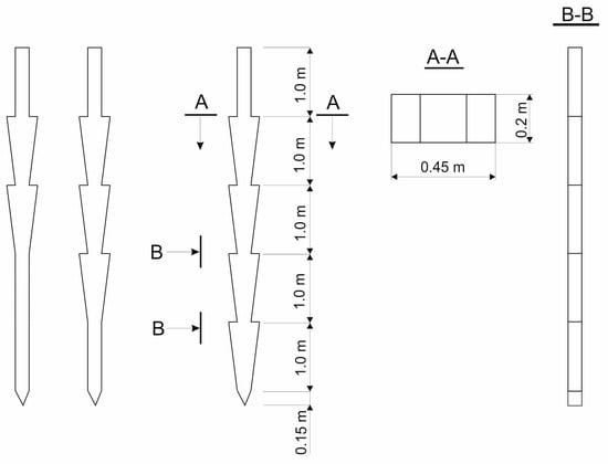 Figure 1. Hybrid shaft pile diagram.
Moreover, wedge-shaped elements can be placed along the pile shaft in 1–4 tiers. This feature allows the selective use of piles in different soil conditions depending on their strength characteristics. So, hybrid piles with a smaller number of wedge-shaped elements are recommended for use in compacted, relatively strong soils. And piles with a large number of wedge-shaped elements should be installed in less compacted, loose, and weak soils.
The dimensions of the piles with a hybrid shaft are as follows: total length—5.0 m, length of the prismatic head and wedge-shaped elements—1.0 m, and length of the tip—0.15 m. The cross-sectional dimensions of the pile head are 0.2 × 0.2 m, and the cross-sectional dimensions of the wedge-shaped elements at their top side are 0.45 × 0.2 m.
For field experiments, large-scale models of hybrid shaft piles manufactured at a 1:3 scale were used. Three variants of hybrid shaft piles with two-, three-, and four-tier arrangement of wedge-shaped elements along the shaft were made for comparative evaluation. Information on the dimensions and volumes of the piles is given in Table 1.

Table 1.
Dimensions and volumes of hybrid shaft piles used in the experiments.
The primary load acting on the pile is absorbed and transferred to the soil through the wedge-shaped elements with inclined faces, while the contribution of the pile tip to load-bearing is significantly reduced. This reduction allows for a smaller diameter of the pile shaft, i.e., reduced cross-sectional dimensions of the prismatic portion of the pile. The dimensions of the wedge-shaped elements (45 × 20 cm) were selected to ensure equivalence with the cross-sectional area of a traditional prismatic pile measuring 30 × 30 cm. Thus, the geometric dimensions of piles with hybrid shafts were designed considering their fundamental interaction with the soil, enabling material savings in both concrete and steel during their use.
The carefully designed geometric dimensions of the piles allow for the placement of wedge-shaped elements along the pile shaft in 1–4 tiers. As evidenced by previous studies, the presence of widenings on the pile and an increase in their number significantly enhance the pile’s bearing capacity. This characteristic makes it possible to tailor piles for various soil conditions based on the deformation and strength properties of the foundation.
For instance, hybrid piles with fewer wedge-shaped elements are recommended for use in compacted and relatively strong soils. Conversely, piles with a greater number of wedge-shaped elements are better suited for less compacted, loose, and weak soils due to their superior bearing capacity.
Large-scale models of hybrid shaft piles (hereinafter—piles) were made of reinforced concrete with longitudinal and transverse reinforcement (Figure 2). The longitudinal reinforcement along the pile contour was made in two rows of steel reinforcement bars with a periodic profile and a diameter of 6 mm. For transverse reinforcement, smooth-bore steel wire with a diameter of 2 mm was used, which was spirally wound onto the longitudinal bars. Mutual tying of the longitudinal and transverse reinforcement was carried out with flexible knitting wire (Figure 2a).
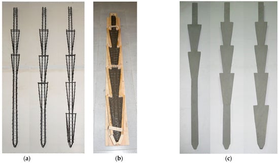
Figure 2.
Reinforcement cages, pile making, and finished reinforced concrete hybrid shaft piles: (a) reinforcement cages; (b) concrete pile forming; (c) ready concrete hybrid shaft piles.
To make the hybrid shaft piles, the formwork was fashioned from wooden boards of appropriate shapes. The pile reinforcement cage was placed in the formwork, and then concrete mortar was poured on top of the cage (Figure 2b). During the process of pouring the concrete mortar and compacting the formwork by vibration, a protective layer of concrete was layered on the outside of the reinforcement cage. After completion of the concrete works, the piles in the formwork were left in storage to harden. After hardening, the piles were removed from the formwork and stored under normal conditions until the concrete had fully matured and gained the required strength within the standard period (Figure 2c).
During the concrete works, concrete samples were taken to form standard concrete cubes with dimensions of 10 × 10 × 10 cm. After gaining strength during the standard period, the concrete cubes were tested by compression to determine their strength (Figure 3). The tests were carried out on a P-125 hydraulic press (Armavir, Moscow, Russia) in accordance with the requirements of the standard [30]. The test results are shown in Table 2.
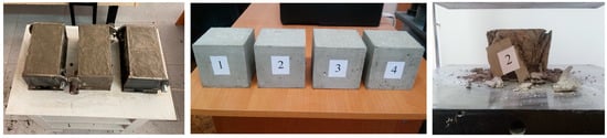
Figure 3.
Control samples of concrete cubes and fragments of their compression tests.
Table 2.
Compression tests results of control samples of pile concrete.
In accordance with the requirements of the standard [30], the compressive strength of concrete R in MPa was determined by the following formula:
where α is the scale factor for converting the concrete strength to the values for samples of the basic size and shape, taken to be equal to 0.95 in accordance with the requirements of the standard [30]; F is the breaking load, N; A is the cross-section area of the sample, mm2; Kw is the correction factor considering the humidity of the samples at the testing time, taken to be equal to 1.0 in accordance with the requirements of the standard [30].
Based on the test results, given in Table 2, it was established that the strength of the control samples of pile concrete (20 MPa) complied with the required standards of concrete strength class B15.
The field tests were carried out on the experimental site of the South Kazakhstan Branch of JSC Kazakh Research Institute of Construction and Architecture. The experimental site was a pit with dimensions of 6.0 × 3.0 m and depth of 3.0 m. The pit was filled layer by layer with light sandy loam and leveled. After completion of the soil preparation works in accordance with the requirements of the standard [31] and the penetration method, the characteristics of the soil base were determined, which are given in Table 3.
Table 3.
Testing site soil parameters.
The gravel and sand of uniform composition, as the natural and most frequently used materials in construction, were used as loose materials (Figure 4). The maximum size of large gravel particles was 25 mm. At the same time, the proportion of the mass of large aggregate to the mass of fine sand in the gravel composition was 35/65.
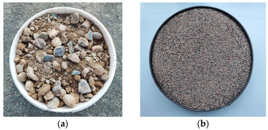
Figure 4.
Loose materials added when driving piles with hybrid shaft: (a) gravel with a maximum particle size of D = 25 mm; (b) sand of medium size.
A mechanized installation for driving piles and conducting static tests was utilized during field tests of piles with hybrid shafts. Detailed information regarding the structural elements and operating procedure of the experimental installation is provided in ref. [32]. The piles were driven using the impact method. To protect the pile head from damage during impacts, a metal cap was employed. A 2 cm thick wooden shock absorber was placed in the recess of the cap to absorb the impact energy.
During the driving process, energy parameters such as the impactor mass (40 kg), drop height (0.5 m), and the potential energy of each impact (196.2 N) were recorded. Additionally, the total number of impacts required to fully drive the piles into the soil was calculated. The piles driven to depths ranging from 138.2 to 138.6 cm.
To achieve the research objectives, loose materials were added during pile driving (Figure 5). A funnel was used to facilitate this process, ensuring that the material did not scatter and was concentrated around the pile shaft. Under the influence of shock pulses, the loose material gradually penetrated into the space between the pile and the surrounding soil. The useful volume of loose material introduced into the soil was calculated to evaluate its contribution to the process.
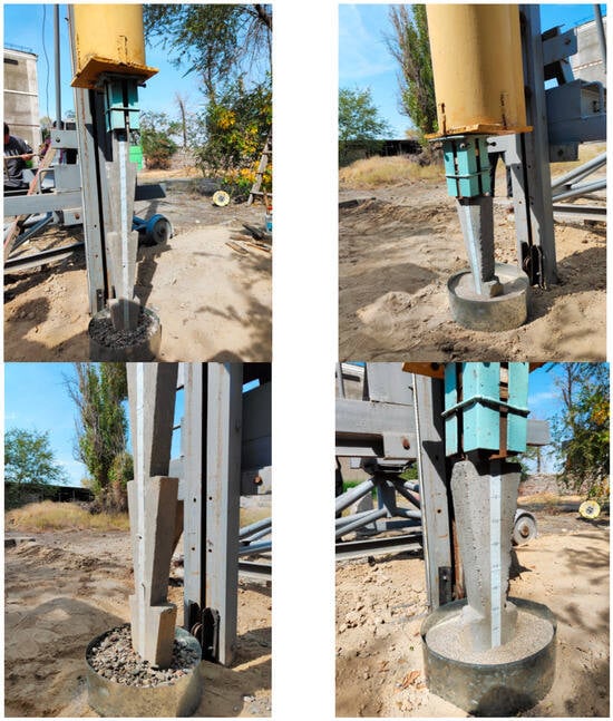
Figure 5.
Impact driving of hybrid shaft piles with gravelly and sandy additives.
Static tests of the piles were conducted in accordance with the requirements of the standard [33]. Loads were applied to piles in stages, with each stage proceeding only after achieving conditional stabilization of deformation. Lifting forces were transferred to the piles using roller-rope systems, which were tensioned by load blocks. Vertical displacements (pile uplift) were measured using an IChTs-12 indicator (Stroipribor, Chelyabinsk, Russia) with an accuracy of up to 0.001 mm (Figure 6). The pulling-out process continued until the “breakdown” phase was reached—defined as the point at which the pile’s ultimate resistance was fully realized.
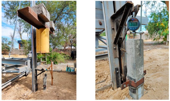
Figure 6.
Static testing to uplift loads of hybrid shaft piles driven with adding of loose materials.
The characteristic value of pile uplift resistance was established by Formula (2) in accordance with the requirements of the set of rules [34]:
where Rt;k is characteristic value of the pile uplift resistance; (Rt;m)min is the lowest measured pile uplift resistance depending on the number of tests; ξ2 is a correction factor for assessing of the pile testing results, taken as 1.40 (for n = 1); n is the number of pile tests.
3. Research Results and Discussion
Pile driving and comparative evaluation of the results were performed separately for each type of pile. The experimental piles were driven with the addition of sand and gravel. To perform a comparative evaluation of the driving data of the experimental piles, a control pile was driven without any addition. The experimental data on driving hybrid shaft piles are given in Table 4, Table 5 and Table 6. The dependences of the pile driving depth on the number of blows are shown in Figure 7, Figure 8 and Figure 9.
Table 4.
Experimental data on driving the first type of hybrid shaft piles.
Table 5.
Experimental data on driving the second type of hybrid shaft piles.
Table 6.
Experimental data on driving the third type of hybrid shaft piles.
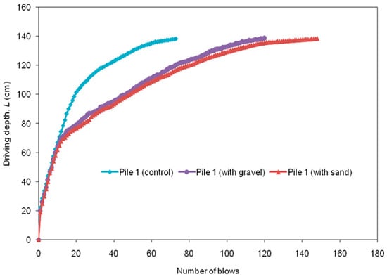
Figure 7.
Dependence of the immersion depth of the first type of hybrid shaft piles on the number of blows.
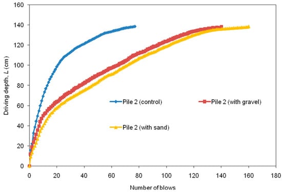
Figure 8.
Driving depth vs. number of blows of the second type of hybrid shaft piles.
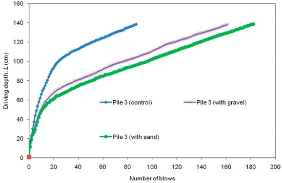
Figure 9.
Driving diagrams of the third type of hybrid shaft piles.
As can be seen from the experimental results, the process of driving hybrid shaft piles allows identifying the following main features:
- -
- In the same soil conditions, the energy intensity of driving testing piles (piles driven with the addition of loose materials) depending on the type (1–3) of piles is 1.64–2.03, 1.82–2.08, and 1.85–2.09 times higher, respectively, than the energy intensity of driving control piles;
- -
- The specific energy intensity of experimental driving piles of 1–3 types (per unit volume of the driven part of the pile) is 1.639–2.024, 1.820–2.077, and 1.854–2.092 times higher, respectively, compared to the specific energy intensity of driving control piles;
- -
- The largest useful volume of loose additives (used during driving) is typical for sand at 118.2 cm3, 254.9 cm3, and 391.1 cm3 against the minimum volume of gravel at 107.8 cm3, 245.3 cm3, and 380.0 cm3, depending on pile types 1–3, respectively;
- -
- The volumes of sand introduced during driving of 1–3 piles types are 9.65%, 3.91%, and 2.92% higher than the volumes of gravel, respectively;
- -
- The energy consumption for driving 1–3 pile types per unit of sand volume is 1.46 times, 1.27 times, and 1.25 times higher, respectively, than per unit of gravel;
- -
- Increasing the volume of the wedge-shaped elements of the pile shaft by 2–3 times causes increasing volumes of loose materials introduced during driving: gravel by 115.65% and sand by 230.88%;
- -
- An increase in the volume of wedge-shaped elements of the pile shaft by 2–3 times causes an increase in the energy costs of pile driving by 16.67–34.17% when adding gravel and by 8.11–22.97% when adding sand;
- -
- With an increase in the volume of wedge-shaped elements of the pile shaft by 2–3 times, the specific energy consumption of pile driving increases by 16.86–34.57% when adding gravel and by 8.04–22.98% when adding sand.
The analysis of the obtained results of experiments on driving hybrid shaft piles shows that the use of loose materials increases the energy capacity of piles driving. Compared to the control pile (driven without the use of loose additives), driving the testing piles (with the addition of sand and gravel) is a more energy-intensive process (energy intensity is 1.64–2.09 times higher). Moreover, the maximum rise of energy intensity of driving is observed when using sand rather than gravel. This is explained by the small size of sand particles and their homogeneous composition, which fills the space between the pile and the surrounding soil better and in greater volume, clamping the shaft more strongly. As a result, it increases the pile shaft clamping force, reducing the pile refusal during driving, which increases the energy intensity of hammering.
Increasing the energy capacity of the pile driving process is a consequence of raising the volume of the pile shaft. This is caused by the increasing number of wedge-shaped elements of the pile shaft when raising their number as much as their volume and the volume of free space (slots) between them, which is filled with loose material. Therefore, with the growth of slot volume between the wedge-shaped elements of the pile shaft, the volume of loose additives, filled during the driving of the hybrid shaft pile, is also raised.
To calculate the useful volume of added loose material, a formula considering the volumes of the wedge-shaped elements of the shaft and the volumes of the formed slits (free space) between them can be proposed. For this, we determined the dependence of the ratio vp/vu (where vp is the useful volume of loose material introduced into the slits between the widenings during driving (cm3); vu is the volume of slits (free space) between the wedge-shaped elements of the shaft (cm3)) on the volume of the wedge-shaped elements of the pile shaft Vs, which is mathematically described by a polynomial function (Figure 10). The formula of the function can be transformed into the following formula for determining the useful volume of loose material vp:
where φ, β, and λ parameters are taken from Table 7; Vs is the volume of wedge-shaped elements of the pile shaft (cm3).
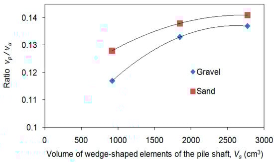
Figure 10.
vp/vu ratio vs. volume of wedge-shaped elements of the pile shaft Vs.
Table 7.
Parameters φ, β, and λ in Formula (3).
A comparative analysis of experimental data on driving piles with hybrid shaft shows that as the volume of their wedge-shaped elements increases, the specific energy capacity of their driving EΔ also increases (Table 4, Table 5 and Table 6). This dependence allows us to propose Formula (4), used to determine the amount of energy spent on driving a unit volume of a pile. The proposed formula is described by the function shown in Figure 11.
where j, p, and m are parameters taken from Table 8.
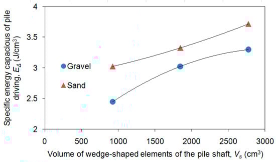
Figure 11.
Dependence of the growth of the specific energy intensity of driving on the volume of wedge-shaped elements of the pile shaft.
Table 8.
Parameters j, p, and m in Formula (4).
There is a relationship between the pile volume increasing and an increase in the pile driving energy capacity for a unit volume of additive ev (Table 4, Table 5 and Table 6). This dependence is described by Formula (5) and shown in Figure 12. It allows calculating the amount of energy required for driving piles per specific volume of material introduced as backfill.
where g, z, and b parameters are taken from Table 9.
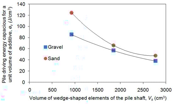
Figure 12.
Dependence of the energy capacity of a unit volume of additive ev on the volume of wedge-shaped elements of the pile shaft.
Table 9.
Parameters g, z, and b in Formula (5).
The results of static tests of hybrid shaft piles on uplift loads are presented in Table 10, Table 11 and Table 12. The dependences of the pile displacement on the applied load are graphically shown in Figure 13, Figure 14 and Figure 15.
Table 10.
Experimental data on the uplift capacity of the first type of hybrid shaft piles.
Table 11.
Experimental data on the uplift capacity of the second type of hybrid shaft piles.
Table 12.
Experimental data on the uplift capacity of the third type of hybrid shaft piles.
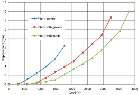
Figure 13.
Dependence of the displacement of the first type of hybrid piles on the applied uplift load.
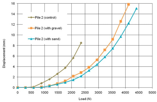
Figure 14.
Dependence of the displacement of the second type of hybrid shaft piles on the applied uplift load.
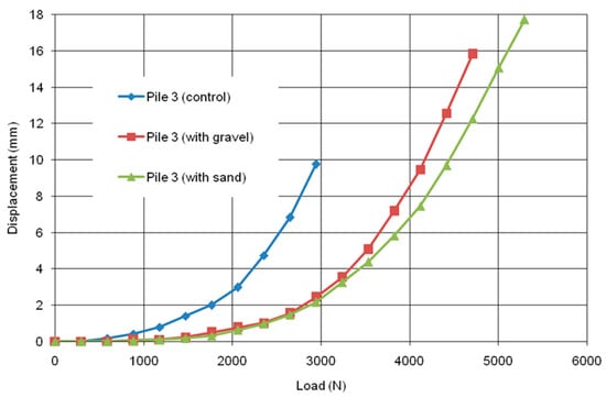
Figure 15.
Dependence of the displacement of the third type of hybrid shaft piles on the applied uplift load.
Experimental data on the uplift capacity of hybrid shaft piles reveal the following features of their behavior:
- -
- The bearing capacity of piles driven with the addition of loose materials during uplift loads is significantly higher than the bearing capacity of piles driven without them. So, the bearing capacity of pile 1, pile 2, and pile 3 driven with the addition of gravel is 1.83 times, 1.75 times, and 1.60 times higher than the bearing capacity of the control pile. And upon pulling out the same piles driven with sand, their bearing capacity relative to the control piles is 2.17 times, 1.88 times, and 1.80 times higher, respectively;
- -
- Increasing the volume of the wedge-shaped elements of the pile shaft causes an increase in their uplift resistance. So, an increase in the volume of wedge-shaped elements of the pile shaft by 2–3 times contributes to an increase in their uplift resistance by 1.27–1.45 times in the case of using gravel and by 1.15–1.38 times when adding sand;
- -
- The uplift resistance of a unit volume of loose material is higher for piles driven with sand rather than gravel. For pile 1, pile 2, and pile 3, this excess is 1.28 times, 1.12 times, and 1.29 times, respectively.
The analysis of the obtained experimental data of the results of static tests of hybrid shaft piles shows that the introduction of loose materials significantly increases their bearing capacity, which reaches 1.60–2.17 times. The achieved resistance increases for hybrid shaft piles is a consequence of the soil compaction around the pile and the increase in the volume of the compacted zone involved in the pile work due to the introduction of additional material. This effect increases with the increase in volume of the wedge-shaped elements of the pile shaft. So, it is known that the volumes of the slots (empty space) between the wedge-shaped elements of hybrid shaft piles are for pile 1924 cm3, for pile 21,848 cm3, and for pile 32,772 cm3 (Table 1). Considering that these volumes for each pile equal to 100%, their filling with loose material after driving is as follows: when using sand, 12.79%, 13.79%, and 14.11%, respectively, for pile 1, pile 2, and pile 3; when using gravel, 11.67%, 13.27%, and 13.71%, respectively, for pile 1, pile 2, and pile 3. Therefore, filling the space around and under the inclined edges of the piles with loose material by even an average of 11–14% ensures an increase in their uplift resistance by 60–117%. This is an attractive enough effect to recommend this pile driving technology for consideration in practical application.
As for the increased effect of using sand relative to gravel, as can be seen from the analysis of the results, this is facilitated by the larger useful volume of introduced sand. Due to the friability, uniform pourability, and incompressibility, smaller sand particles better fill the space between the pile and the soil, forming a compacted zone under the inclined edges of the wedge-shaped elements of the pile. The thrust effect of the widened parts of the pile due to the repulsive forces increases the shear force when lifting the pile upward, as a result of which the resistance of the soil increases, affecting the increase in its bearing capacity.
A comparative analysis of the experimental data of the static tests of hybrid shafts piles by uplift loads shows that their bearing capacity increases as the volume of the wedge-shaped elements of the pile shaft also increases. In other words, the resistance of a hybrid pile depends on the volume of the wedge-shaped elements of the shaft (widenings) and the type as well as the volume of introduced loose material, which can be determined by calculation. This pattern can be described by Formula (6), (Figure 16), which allows determination of the bearing capacity of a pile by calculation based on the volume of its widened elements.
where k, q, and x parameters are taken from Table 13.
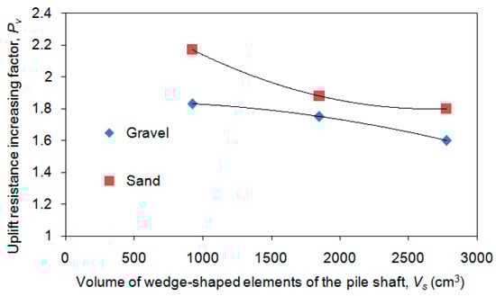
Figure 16.
Dependence of the uplift resistance Pv on the volume of wedge-shaped elements of the pile shaft.
Table 13.
Parameters k, q, and x from Formula (6).
The uplift resistance of a unit volume of loose material fv changes with an increase in the volume of wedge-shaped elements of the pile shaft. The correlation dependence establishing this feature is described by Formula (7) (Figure 17). The presented formula allows us to determine the specific force of the introduced material that is spent on its shift when pulling out the pile, depending on its volume.
where ε, π, and ω parameters are taken from Table 14.
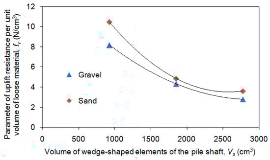
Figure 17.
Dependence of the uplift resistance of a unit volume of loose material fv on the volume of wedge-shaped elements of the pile shaft.
Table 14.
Parameters ε, π, and ω from Formula (7).
Based on the analysis of the obtained experimental data from the study of the energy intensity of driving the hybrid shaft piles and their comparison with the results of our previously performed experimental studies described in refs. [13,27], it is possible to propose a formula for calculating the comparative energy intensity of the studied piles relative to conventional pyramidal or prismatic piles in the following form:
where QA is the hybrid shaft pile driving energy by the proposed technology (with loose material); Ωω is the comparative coefficient for driving a control hybrid shaft pile without any adding (considering energy intensity) [13,27]; Hσ is the conventional shape (pyramidal or prismatic) pile driving energy; Dτ is the coefficient considering the type of piles and adding (loose) material (Table 15).
Table 15.
Coefficient considering the type of piles and adding (loose) material Dτ.
Formula (8) is intended for calculating the comparative energy intensity of driving piles with a hybrid shaft relative to the energy intensity of driving conventional pyramidal or prismatic piles. Based on this formula, using data from conventional piles, it is possible to calculate the amount of energy required for driving piles with a hybrid shaft with the introduction of loose material.
From the data in Table 15, it follows that the energy capacity of driving hybrid shaft piles with the considered technology (using loose material) can be 1.4–3.5 times higher than the energy consumption for driving conventional piles.
In a similar way, as a result of comparing the experimental data of the present and our previously conducted studies [13,27], it is possible to obtain the following Formula (9). It allows calculation of the bearing capacity of piles with a hybrid shaft when they are pulled out of the soil, based on already known experimental data on the pull-out capacity of pyramidal and prismatic piles.
where Bd is the uplift resistance of a hybrid shaft pile driven using loose material; Up is the comparative uplift resistance of a control hybrid shaft pile [27]; Rs is the uplift resistance of a conventional shape (pyramidal or prismatic) pile; Gα is the coefficient considering the type of piles and additives (Table 16).
Table 16.
Coefficient considering the type of piles and additives Gα.
As can be seen from the data in Table 16, the uplift resistance of hybrid shaft piles, driven using the proposed technology (using loose material), can significantly (1.5–4.4 times) exceed the uplift resistance of conventional piles driven in the common way.
4. Conclusions
The experimental studies on the driving energy capacity and uplift resistance of hybrid shaft piles revealed the following key features of the pile’s behavior:
- Energy Consumption of Driving:
The impact driving technology for hybrid shaft piles with the addition of loose materials requires 1.64–2.09 times more energy compared to driving without such materials. The energy consumption depends on the type and volume of the introduced material. The useful volume of sand in the soil during driving is 2.92–9.65% greater than that of gravel. Consequently, driving piles with gravel is comparatively less energy-intensive, while driving with sand requires more energy. Additionally, increasing the volume of the wedge-shaped elements of the pile shaft by 2–3 times results in an 8.04–34.57% increase in energy consumption, as larger wedge-shaped elements necessitate the introduction of a greater volume of loose material.
- 2.
- Uplift Resistance:
The uplift resistance of hybrid shaft piles driven with loose materials is 1.60–2.17 times higher than that of piles driven without them. Increasing the volume of the wedge-shaped elements and loose materials further enhances the load-bearing capacity of the pile during pulling out by up to 1.15–1.45 times.
- 3.
- Effect of Loose Materials:
The type of loose material added during driving significantly impacts the resistance of piles to pulling loads. Piles driven with sand exhibit relatively higher resistance, whereas those driven with gravel show the lowest resistance. The bearing capacity of piles during pulling with a sand additive is 1.07–1.18 times higher than that of piles driven with gravel.
- 4.
- Influence of Wedge-Shaped Elements:
Increasing the volume of wedge-shaped elements in the pile shaft positively influences the bearing capacity of hybrid shaft piles. A two- or three-fold increase in the volume of these elements enhances the bearing capacity during pulling out by 15.4–27.3% and 38.5–45.5%, respectively. The addition of loose materials during driving, which clamps the shaft more effectively, further increases the resistance of hybrid shaft piles by 60–117%.
- 5.
- Energy Efficiency vs. Resistance:
The driving technology for hybrid shaft piles is 1.4–3.5 times more energy-intensive than the driving of pyramidal and prismatic piles without loose materials. However, in terms of resistance to pulling loads, hybrid shaft piles are 1.5–4.4 times more effective than traditional piles driven without material additives.
- 6.
- Correlation Dependencies:
The correlation dependencies derived from the research results are highly reliable and can be used to calculate the relative energy intensity of driving and the bearing capacity of hybrid shaft piles for pulling loads during impact driving with gravel and sand additives.
5. Practical Significance and Research Prospects
The results of the conducted research hold significant importance for the engineering practice of constructing pile foundations for buildings and structures, particularly for those with substantial height and a small supporting area. These structures require enhanced resistance to pulling out and stability against overturning, making the application of the tested pile driving technology both justified and cost-effective.
Based on the experimental data obtained, it becomes feasible to determine, already at the design stage, the optimal hammer impact energy for efficiently driving hybrid shaft piles. Additionally, a methodology and program for testing the studied piles and their associated foundations can be developed for on-site implementation using the proposed technology.
The calculation formulas derived from this research provide a reliable means of assessing the energy intensity of driving piles with loose material compared to conventional piles (pyramidal or prismatic). They also enable the evaluation of the bearing capacity of hybrid shaft piles under pulling loads during the variant design stage of foundation development.
The generalized experimental data from this study will further support the creation of guidelines for the application of pile construction methods incorporating the proposed technology of driving with additional soil compaction. These advancements will accelerate the adoption of hybrid shaft piles into construction practices and contribute to cost reductions in reinforced concrete due to the increased bearing capacity of these innovative piles and their installation methods.
At the same time, the conducted studies and the obtained results do not exhaust the potential of hybrid shaft piles and their remarkable performance characteristics. While the current research focuses on the bearing capacity of these piles under static loads, studying their behavior under dynamic loads presents an even greater area of interest. Considering the design features of hybrid shaft piles, such as wedge-shaped inclined edges and the possibility of increasing their number along the shaft as well as the proposed driving technology with the introduction of loose materials, dynamic loads are likely to enhance the compaction of added backfill and surrounding soil. This, in turn, may result in the formation of a compacted core beneath the wedge-shaped elements and around the pile shaft, thereby increasing soil resistance due to improved clamping of the shaft.
Equally important is the investigation of the performance of groups of hybrid shaft piles connected by a common grillage. Such configurations are likely to amplify the positive effects of these piles, as the combined increase in bearing capacity would result from the cumulative effect of additional wedge-shaped elements and the increased useful volume of introduced loose materials.
Additionally, understanding the resistance parameters of hybrid shaft piles to horizontal loads, both in natural soils and embankments, is of practical interest. Further studies could yield significantly improved results by exploring hybrid piles with wedge-shaped elements arranged on all four sides of the shaft, representing an evolution of the current pile design.
These and other aspects of the behavior of hybrid shaft piles warrant detailed investigation and experimental validation, which form the basis for our prospective research endeavors.
Author Contributions
Conceptualization, I.B. and Y.A.; methodology, I.B. and Y.A.; formal analysis, I.B., Y.A., and N.S.; writing—review and editing, I.B. and Y.A.; supervision I.B.; writing—original draft, Y.A. and N.S.; visualization, Y.A. and N.S.; funding acquisition, investigation, and validation, Y.A.; resources N.S. All authors have read and agreed to the published version of the manuscript.
Funding
This research has been funded by the Science Committee of the Ministry of Science and High Education of the Republic of Kazakhstan (Grant No. AP15473198). Any opinions, findings, conclusions, or recommendations expressed in this material are those of the researchers and do not necessarily reflect the views of the Ministry of Science and High Education of the Republic of Kazakhstan.
Data Availability Statement
Data will be made available on request.
Acknowledgments
The authors are grateful to the Science Committee of the Ministry of Science and High Education of the Republic of Kazakhstan.
Conflicts of Interest
The authors declare no conflicts of interest.
References
- Nagai, H.; Tsuchiya, T.; Shimada, M. Influence of installation method on performance of screwed pile and evaluation of pulling resistance. Soils Found. 2018, 58, 355–369. [Google Scholar] [CrossRef]
- Umezaki, T.; Kawamura, T.; Okamoto, K.; Hattori, A.; Kobayashi, Y. Swelling properties and coefficient of permeability of friction-reducing polymer for pull-out of temporary sheet piles. Soils Found. 2018, 58, 797–807. [Google Scholar] [CrossRef]
- Jiang, X.; Li, K. Researchon Pull-out Mechanical Characteristics of Pile Foundation in Submerged Floating Tunnel. Procedia Eng. 2016, 166, 389–396. [Google Scholar] [CrossRef]
- Chang, D.W.; Lin, C.; Wang, T.Y.; Lin, Y.K.; Lu, F.C.; Kuo, C.J. Three-dimensional Finite Element Analyses of Barrette Piles under Compression and Uplift Loads with Field Data Assessments. Geotech. Eng. J. SEAGS AGSSEA 2019, 50, 00465828. [Google Scholar]
- Burke, T.S.d.S.; Jacobsz, S.; Elshafie, M.Z.E.B.; Osman, A.S. Measurement of pile uplift forces due to soil heave in expansive clays. Can. Geotech. J. 2022, 59, 2119–2134. [Google Scholar] [CrossRef]
- Tomlinson, M.; Woodward, J. Pile Design and Construction Practice, 5th ed.; Taylor&Francis: Abingdon, UK, 2008. [Google Scholar] [CrossRef]
- Kuwahara, S.; Inazumi, S. Settlement of surrounding grounds due to existence of pile pulling-outholes. Int. J. Geomate 2019, 16, 81–85. [Google Scholar] [CrossRef]
- Bekbasarov, I.; Nikitenko, M.; Shanshabayev, N.; Atenov, Y.; Moldamuratov, Z. Tapered-prismatic pile: Driving energy consumption and bearing capacity. News Natl. Acad. Sci. Repub. Kazakhstan Ser. Geol. Tech. Sci. 2021, 6, 53–63. [Google Scholar] [CrossRef]
- Bekbasarov, I.; Atenov, Y. Equations Used to Calculate Vertical Bearing Capacity of Driven Piles with Shaft Broadenings. Period. Civ. Eng. 2020, 64, 1235–1243. [Google Scholar] [CrossRef]
- Bekbasarov, I.; Shanshabayev, N. Driving Features of Tapered-Prismatic Piles and Their Resistance to Static Loads. Acta Montan. Slovaca 2022, 4, 55–65. [Google Scholar]
- Bekbasaov, I.; Shanshabayev, N. Impact Dipping Pyramidal-Prismatic Piles and their Resistance to Pressure and HorizontalLoad. Period. Polytech. Civ. Eng. 2021, 65, 909–917. [Google Scholar] [CrossRef]
- Isabai, B.; Nurzhan, S.; Yerlan, A. Strength Properties of Various Types of Fiber-Reinforced Concrete for Production of Driven Piles. Buildings 2023, 13, 1733. [Google Scholar] [CrossRef]
- Bekbasarov, I.; Shanshabayev, N.; Atenov, Y. Impact-Driven Penetration of Multi-Strength Fiber Concrete Pyramid-Prismatic Piles. Buildings 2024, 14, 3595. [Google Scholar] [CrossRef]
- Kupchikova, N.V. Numerical researches of the work of the pile with end spherical broadening as part of the pile group. Constr. Reconstr. 2019, 6, 3–9. [Google Scholar] [CrossRef]
- Hirai, Y.; Wakai, S.; Aoki, M. In-situ pull-out tests of cast-in-place concrete piles with belled enlargements. Jpn. Geotech. Soc. Spec. Publ. 2016, 2, 1478–1481. [Google Scholar] [CrossRef]
- Carvalho, D.; Albuquerque, P. Uplift behavior of bored piles in tropical unsaturated sandysoil. In Proceedings of the 18th International Conference on Soil Mechanics and Geotechnical Engineering, Paris, France, 2–5 September 2013; pp. 2707–2710. [Google Scholar]
- Yang, B.; Ma, J.; Chen, W.; Yang, Y. Uplift Behavior of Belled Short Piles in Weathered Sandstone. Math. Probl. Eng. 2018, 2018, 8614172. [Google Scholar] [CrossRef]
- Bian, M.; Qin, S.; Peng, J.; Li, J.; Zhang, X. Exploration of the slope effect on the uplift capacity of single straight and belled piles supporting transmission towers. Front. Mater. 2023, 10, 1171601. [Google Scholar] [CrossRef]
- Bekbasarov, I.I.; Atenov, Y.I. Resistance of broadened pile models for horizontal and pulling loads. Bull. L.N. Gumilyov Eurasian Natl. Univ. Tech. Sci. Technol. Ser. 2020, 2, 27–38. [Google Scholar] [CrossRef]
- Rao, K.S.S.; Venkatesh, K. Uplift behaviour of short piles in uniform sand. Soils Found. 1985, 25, 1–7. [Google Scholar]
- Pradiptiya, A.; Yuwono, Y.; Sudardja, H.; Istiatun, I. Mobilization of mini pile uplift resistance in sand. J. Poli-Teknol. 2016, 14, 1–6. [Google Scholar] [CrossRef]
- Mao, Z.; Guo, H.; Wu, Y.; Wang, E.; Li, X. Development of a New Uplift Pile with Prestressed Semi-Bonded Composite Anchor. Buildings 2022, 12, 1478. [Google Scholar] [CrossRef]
- Meeran Mydeen, M.Y.; Madasamy, M.; Seeni, B.S. Uplift Behaviour of External Fibre-Reinforced Polymer Wrapping on RC Piles in Dry and Submerged Sandy Soil. Buildings 2023, 13, 778. [Google Scholar] [CrossRef]
- Hua, L.; Tian, Y.; Gui, Y.; Liu, W.; Wu, W. Semi-Analytical StudyofPile–Soil Interaction on a Permeable Pipe Pile Subjected to Rheological Consolidation of Clayey Soils. Int. J. Numer. Anal. Methods Geomech. 2024. early view. [Google Scholar] [CrossRef]
- Wang, K.; Cao, J.; Ye, J.; Qiu, Z.; Wang, X. Discrete element analysis of geosynthetic-reinforced pile-supported embankments. Constr. Build. Mater. 2024, 449, 138448. [Google Scholar] [CrossRef]
- Wang, K.; Ye, J.; Wang, X.; Qiu, Z. The Soil-Arching Effectin Pile-Supported Embankments: A Review. Buildings 2024, 14, 126. [Google Scholar] [CrossRef]
- Atenov, Y.I. Investigation of the Piles with Flat Shaft Widenings for the Installation of Foundations of Linear Hydraulic Structures. Ph.D. Thesis, Dulaty University, Taraz, Kazakhstan, 2023; 154 p. [Google Scholar]
- Isabai, B.; Yerlan, A.; Nurzhan, S. The Influence of Backfill on the Driving Energy Intensity and Axial Load Resistance of Pileswith Shaft Widenings: Modeling Research. Buildings 2023, 13, 3097. [Google Scholar] [CrossRef]
- Svintsov, A.P.; Rahimullah, A.; Rukosueva, A.A. Construction of foundations in soils with an aquifer. Zhilishchnoe Stroit. 2019, 9, 31–36. [Google Scholar] [CrossRef]
- GOST 10180-2012; Concretes. Methods for Strength Determination Using Reference Specimens. Interstate Standard Inform: Moscow, Russia, 2018; 36p.
- GOST 5180-2015; Soils. Methods for Laboratory Determination of Physical Characteristics. Interstate Standard: Moscow, Russia, 2019; 20p.
- Bekbasarov, I.I.; Baitemirov, M.N.; Atenov, Y.I.; Shanshabaev, N.A. On experimental equipment for driving and testing large-scale pile models in the field. Mech. Technol. Sci. J. 2019, 4, 134–141. [Google Scholar]
- GOST 5686-2020; Soils. Methods for Field Testing of Piles. Interstate Standard: Moscow, Russia, 2020; 65p.
- SP RK EN 1997-1:2004/2011; Geotechnical Design. Part 1. General Rules. Astana, Kazakhstan, 2016; 156p.


Disclaimer/Publisher’s Note: The statements, opinions and data contained in all publications are solely those of the individual author(s) and contributor(s) and not of MDPI and/or the editor(s). MDPI and/or the editor(s) disclaim responsibility for any injury to people or property resulting from any ideas, methods, instructions or products referred to in the content. |
© 2025 by the authors. Licensee MDPI, Basel, Switzerland. This article is an open access article distributed under the terms and conditions of the Creative Commons Attribution (CC BY) license (https://creativecommons.org/licenses/by/4.0/).