Using Nonlinear Simulation to Analyze the Bearing Performance and Engineering Application of Partial Strengthening and Replacement Composite Shear Walls Without Support Roof
Abstract
1. Introduction
2. Analysis of Horizontal Hysteresis Performance of Partial Reinforced Replacement Composite Shear Walls Without Support Roof
2.1. Analysis Method and Case Study Verification
2.2. Analysis Model
2.3. Analysis of Destruction Process and Mechanism
2.4. Load-Bearing Performance Analysis
- (1)
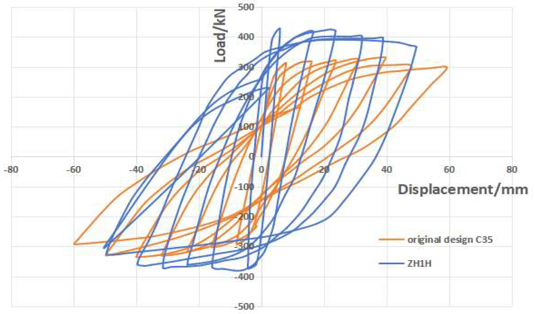
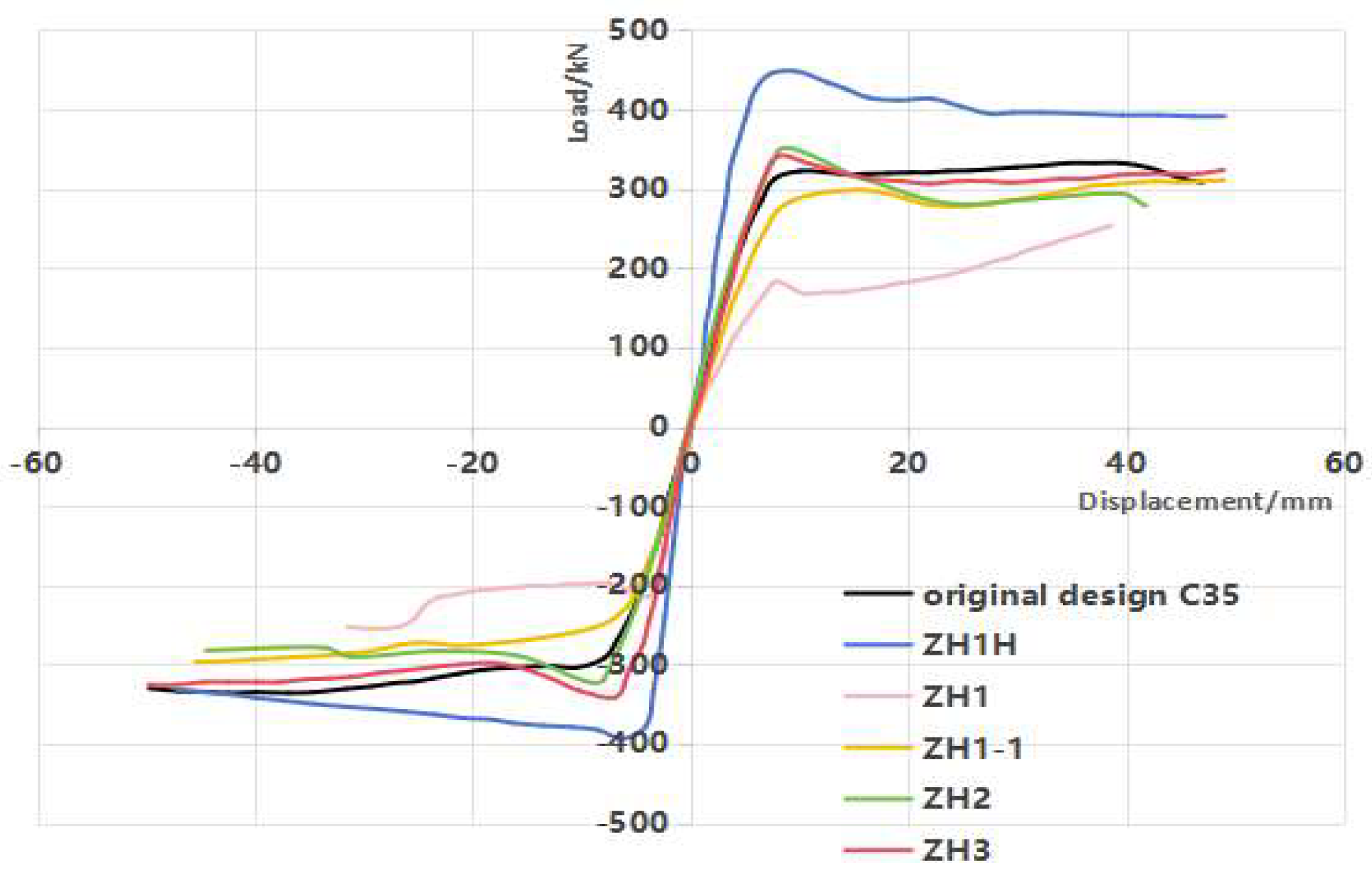
- The skeleton curve of the strengthened replacement composite shear wall model often exhibits a characteristic of initial peak degradation followed by subsequent enhancement. Analysis suggests that this results from the delayed vertical stress effect in the end replacement areas, which gradually becomes active as the non-replacement areas experience stiffness degradation due to the initial vertical stress. From the above figure, it can also be seen that the higher the initial vertical stress level of the model, the greater the amplitude of the skeleton curve’s decrease after passing the peak value and then increasing again. The original design of the shear wall model did not have stress hysteresis, while the end section of the section steel/concrete-reinforced composite shear wall had a relatively high stiffness in the section steel/concrete area, so the characteristic of the skeleton curve of the first two decreasing and then increasing was not obvious.
- (2)
- Comparing the skeleton curves of ZH1, ZH2, ZH3 and the original design C35 shear wall, note that the higher the initial vertical stress level, the lower the ultimate bearing capacity (the highest value of the skeleton curve) of the locally reinforced replacement composite shear wall. This indicates that when the initial vertical stress level is too high, the reinforced composite shear wall will be affected by premature stiffness degradation and the damage to the concrete in the non-replacement area, which will affect the overall reinforcement effect (ZH1).
- (3)
- Comparing the skeleton curves of ZH1 and ZH1H, it can be seen that the use of unsupported local section steel–concrete reinforcement and replacement method not only increases the initial stiffness of the wall, but also maintains high ductility and a relatively full hysteresis loop after reaching the peak bearing capacity. The minimum peak horizontal bearing capacity of composite shear walls is not less than 422 kN, which is greater than the peak horizontal load of defective concrete at 242 kN, and also greater than the original design’s concrete strength of C35 at 327 kN. It can be seen therefore that the reinforcement of RC shear walls via unsupported-roof steel-reinforced concrete local strengthening and replacement can significantly improve the bearing performance of composite shear walls and the collaborative working performance between replacement and non-replacement areas by increasing the bearing capacity on both sides of the end to achieve the ability of composite shear walls to continue bearing even after the concrete damage and softening in the non-replacement area.
- (4)
- Comparing the skeleton curves of ZH1 and ZH1-1, after using batch replacement reinforcement, the vertical stress of the concrete in the middle non-replacement area of ZH1-1 is reduced, which delays the compressive failure of the middle non-replacement concrete. The concrete that was replaced earlier mitigated the stress, reducing the vertical stress on the walls in the non-replacement area and providing stress support for the stress redistribution during the second batch of replacement concrete. At this point, the horizontal ultimate bearing capacity of the specimen is 309 kN, which is 37.6% higher than that of ZH1. In summary, the partial strengthening replacement method without support roof in batches reduces the vertical stress of the middle concrete by increasing the number of replacement and ensuring that the replacement wall participates in the stress, avoiding premature damage and degradation of the concrete in the middle non-replacement area due to excessive vertical stress, and effectively improving the horizontal bearing capacity of the composite shear wall.
3. Vertical Bearing Performance Analysis of Partial Reinforced Replacement Composite Shear Walls Without Support Roof
3.1. Analysis Method and Case Study Verification
3.2. Analysis Model
3.3. Analysis of Destruction Process and Mechanism
3.4. Influence of Initial Vertical Stress Level
4. Nonlinear Simulation Analysis of Reinforced RC Shear Wall Engineering Case Using Unsupported-Roof Local Strengthening and Replacement Method
4.1. Project Overview
4.2. Reinforcement Construction and Simulation Loading Steps
4.3. Overall Model Establishment
4.4. Simulation Analysis Results
- (1)
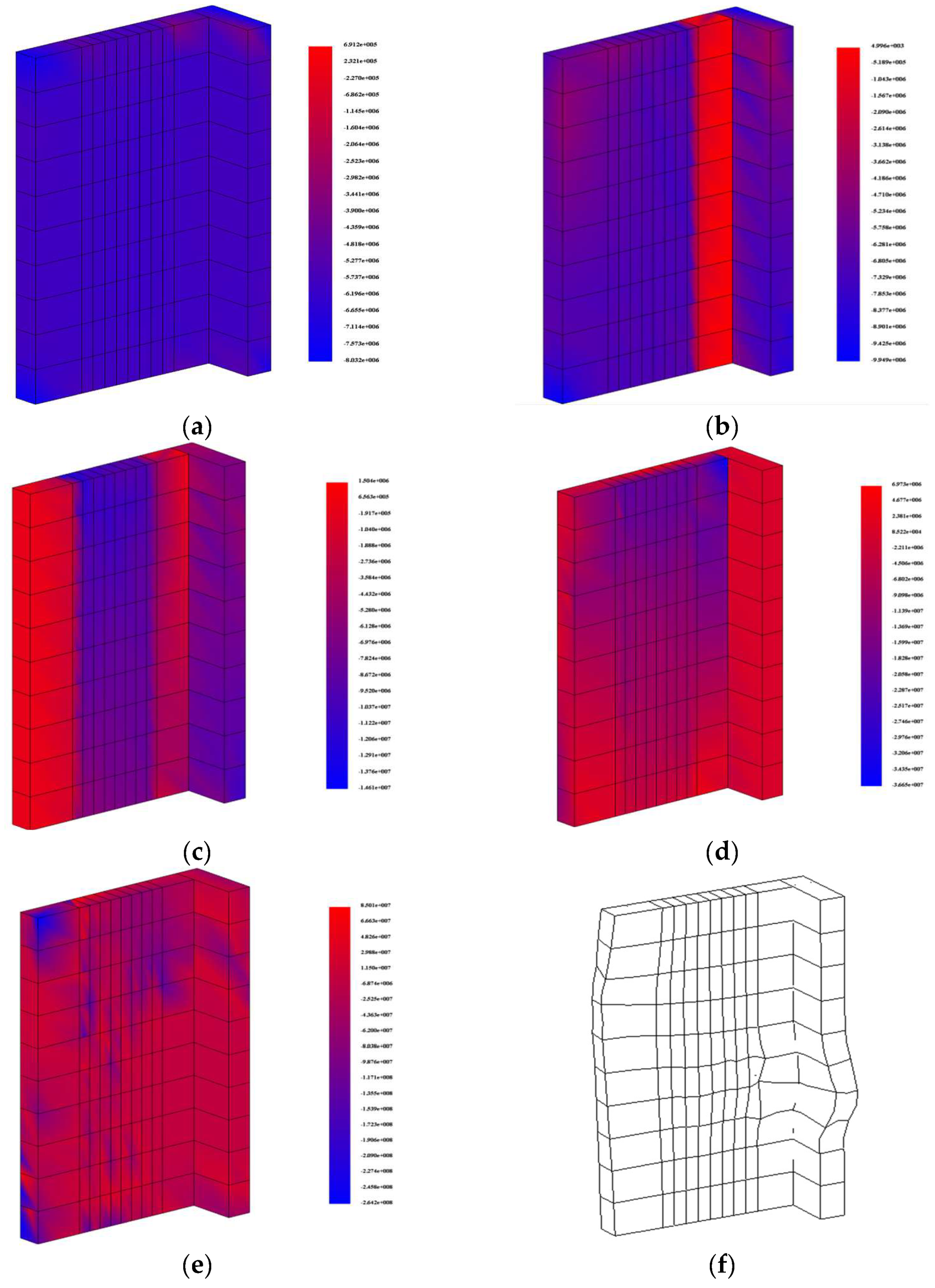
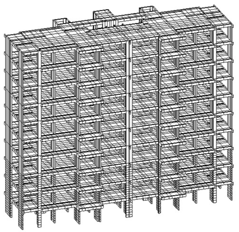
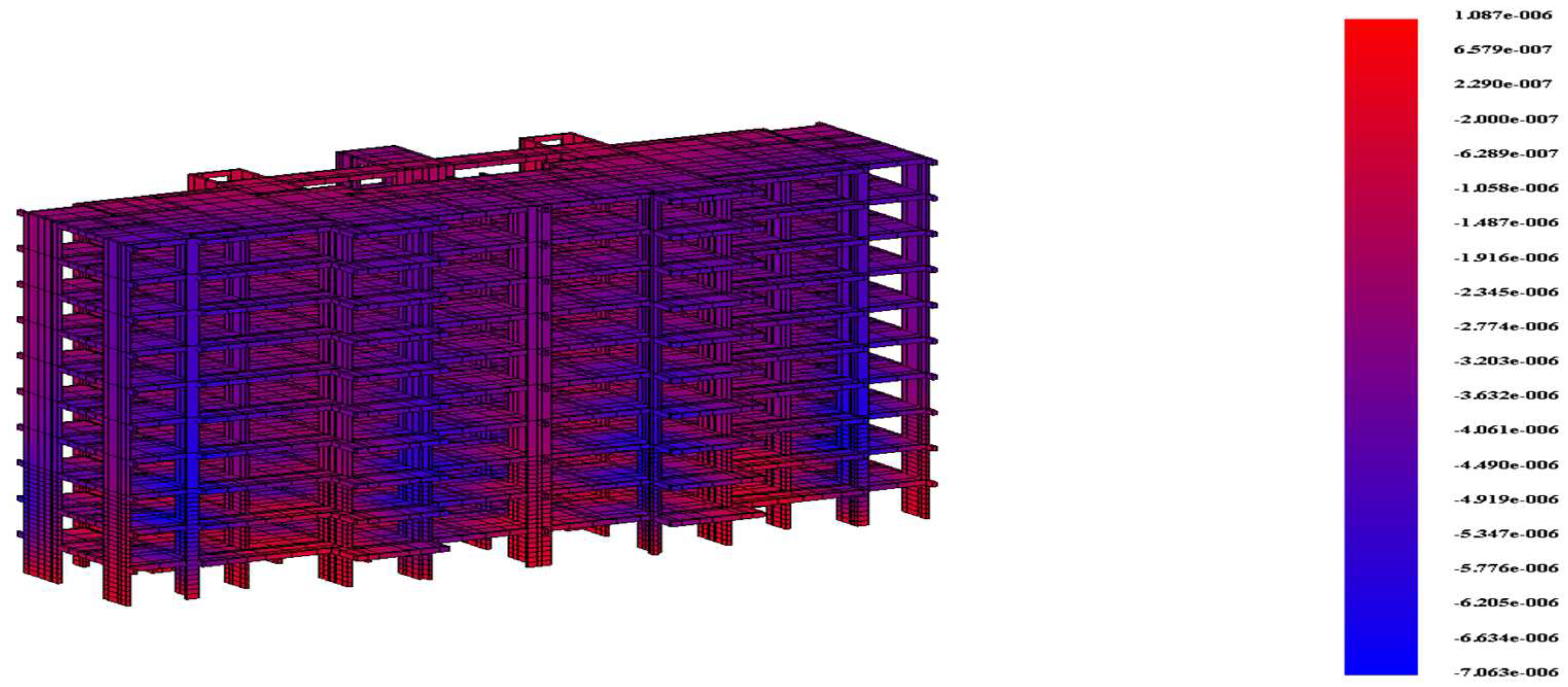
- The initial state of the structure is a shear wall structure that has been built up to the 10th floor; the finite element software calculation results for this state are shown in Figure 19. At this point, except for the stress deviation caused by structural irregularity away from the stairwell shear walls, the stress distribution in each area of the shear walls is homogeneous.
- (2)
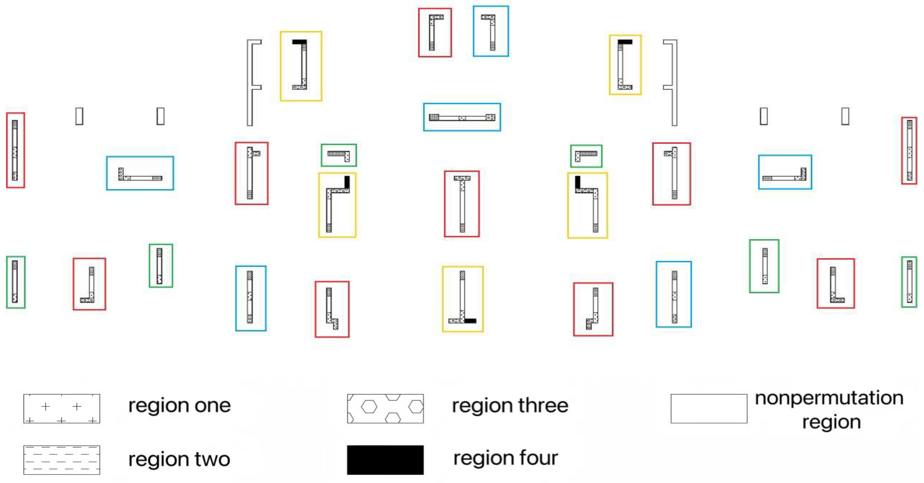
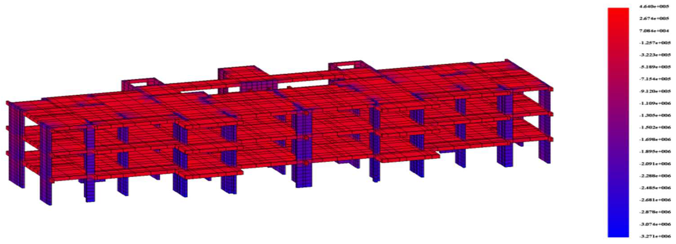
- When the replacement area 2 of the composite shear wall with the red box of 1–3F is filled with high-strength concrete without shrinkage and reaches the design strength, the finite element software calculation results are shown in Figure 20. At this stage, the composite shear wall has already been replaced in area 1, and the vertical displacement of replacement area 2 is reduced compared to replacement area 1, indicating that area 1 has entered work at this stage.
- (3)
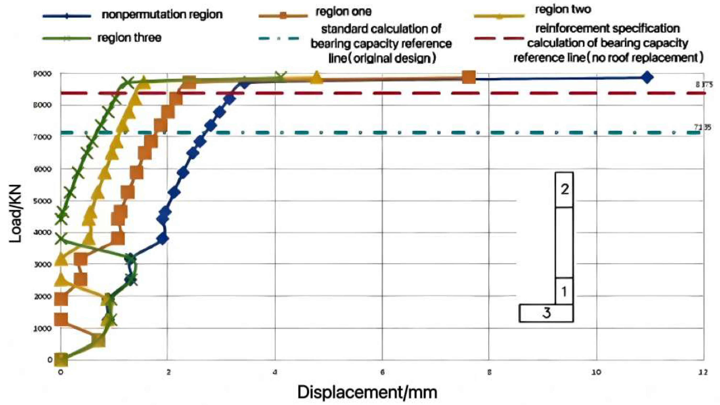
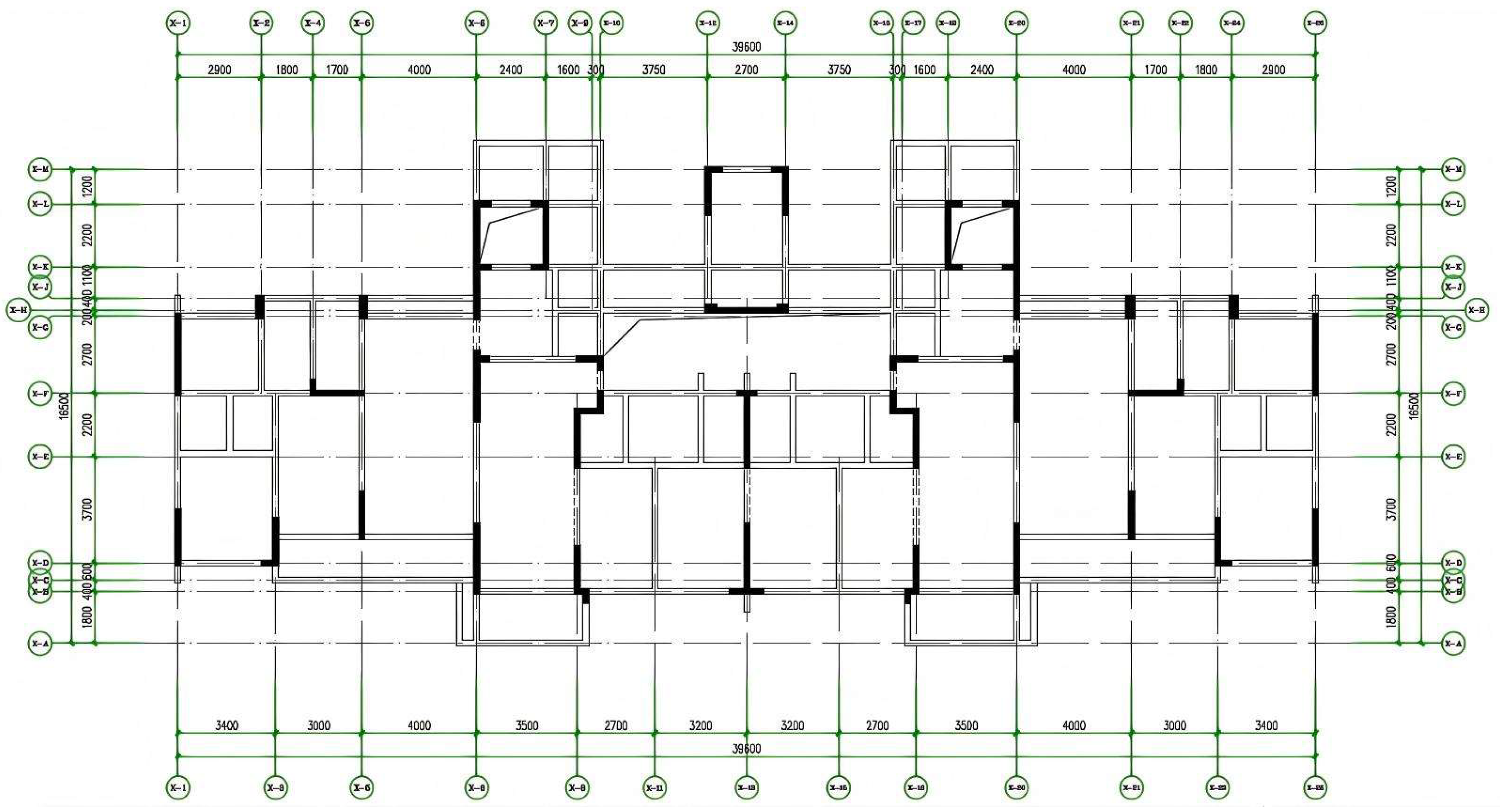
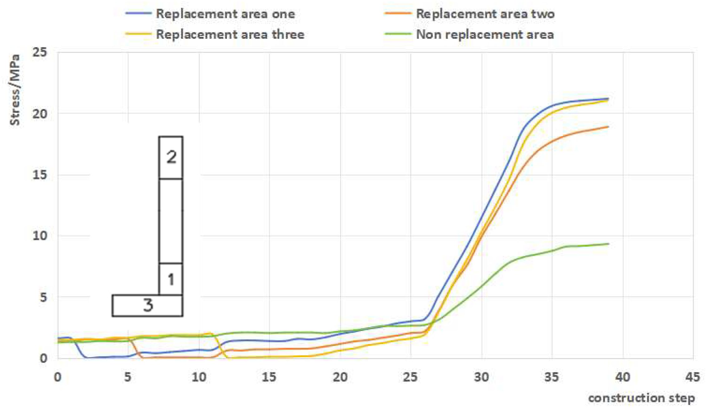
- Due to space limitations, we select an L-shaped wall in the structure (located on the lower left wall in Figure 14) to analyze the stress changes in each section of the wall limbs during the entire construction loading process. Figure 21 shows the vertical stress variation in the wall in different replacement areas throughout the entire process; during the replacement stage, the vertical stress in the non-replacement area remains at a high level. In replacement areas one and two, the vertical stress in area three is slightly higher than that in the non-replacement area, which is mainly due to the uneven deformation of the overall structure. The overall change pattern during the replacement phase is that the area that has been replaced first experiences high stress, while the area replaced later experiences low stress and is added to the overall work. During the construction phase of floors 11–18, the vertical stress in each area steadily increases; under the action of the ultimate load, the non-replacement area is unable to bear higher stress due to the influence of material strength. As the load gradually increases, the stress level in the non-replacement area is the lowest, and the replaced area mainly participates in the stress, playing the role of non-shrinkage high-strength concrete; until the structural loading is completed, the vertical stress in region one is 21 MPa, being 18.9 MPa in region two, and 21 MPa in region three, while the vertical stress in the non-replacement region is only 9.3 MPa.
- (4)
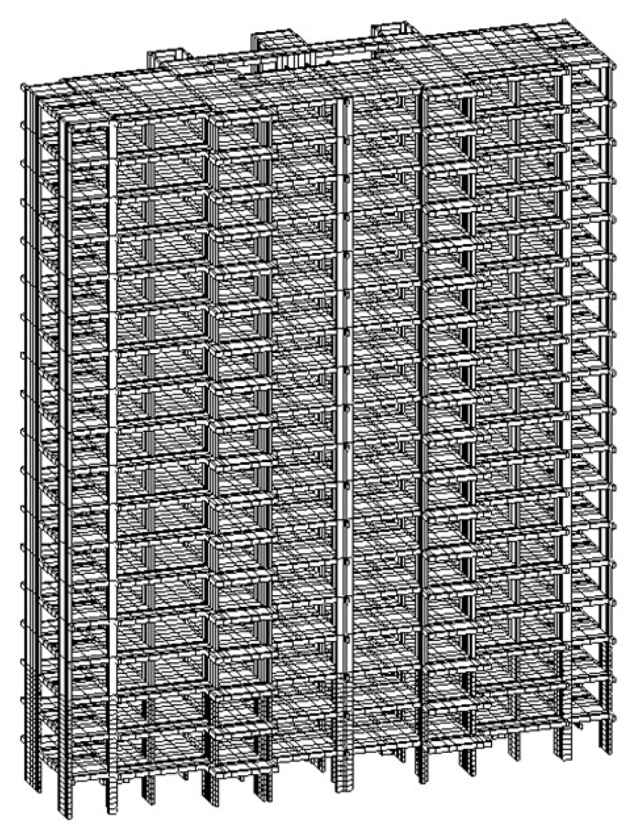
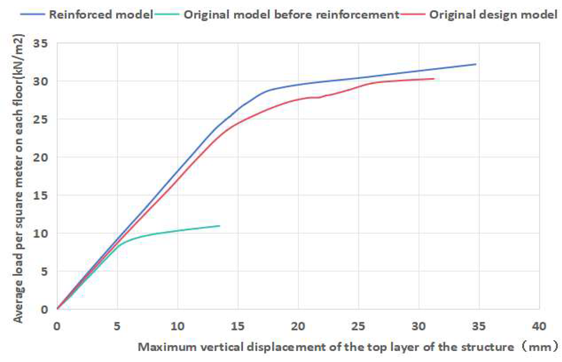
- The vertical ultimate load was applied to the nodes of each floor surface of the original problem structure on the 18th floor (the strength of the shear walls on the 1st–3rd floors did not meet the design requirements). Under the action of the ultimate load, the curve depicting the maximum vertical displacement of the top layer of the structure before and after reinforcement with the change in the load per square meter of the floor surface is shown in Figure 22. It can be seen that the ultimate load of the structure before reinforcement was 10.87 kN/m2, and the maximum vertical displacement of the structure at the time of failure was 13.48 mm; the ultimate load of the original design model was 30.24 kN/m2, and the maximum vertical displacement of the structure at the time of failure was 31.25 mm; meanwhile, the ultimate load of the structure after reinforcement reached 32.15 kN/m2, and the maximum vertical displacement at the time of failure reached 34.73 mm. Compared with the original design and the structure before reinforcement, the bearing capacity and deformation resistance of the reinforced structure have been improved.
- (5)
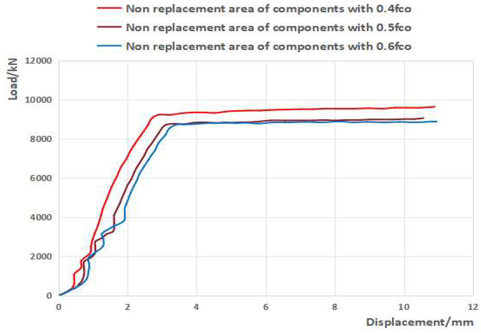
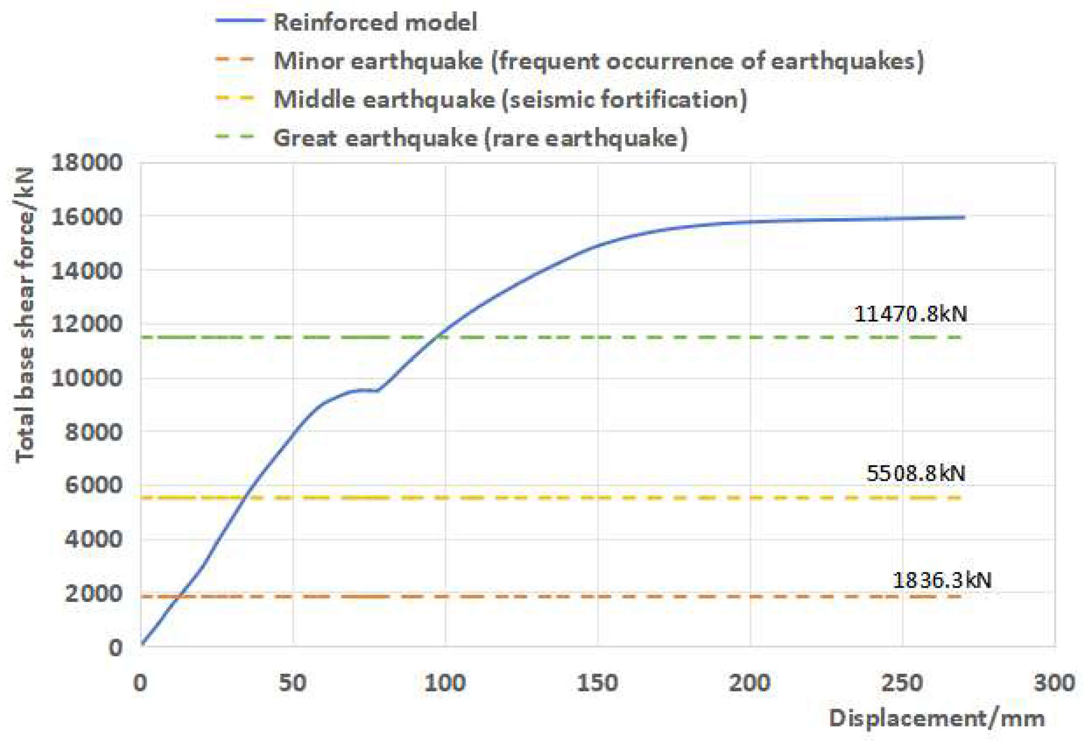
- Figure 23 shows the load–displacement curve of the reinforced overall structure obtained by applying horizontal loads (vertical loads applied at once, horizontal loads applied step by step) according to the “prescribed horizontal force” (seismic code). As shown in the figure, in the early stage of loading, the load–displacement curve roughly changes linearly, and the structure is in the stage of elastic deformation; when the total horizontal load of the structure is applied to 8800 kN, the structure enters the stage of elastic–plastic deformation, and the displacement accelerates with the increase in load. The horizontal ultimate bearing capacity of the reinforced structure can reach 15,906.36 kN, which is about 8.7 times larger compared with the elastic “small earthquake” result of 1836.3 kN (calculated using the PKPM software (Version2020) package), 2.9 times larger compared with the elastic “medium earthquake” result of 5508.8 kN, and 1.4 times larger compared with the elastic–plastic “large earthquake” result of 11,470.8 kN. This indicates that the reinforced overall structure meets the seismic bearing capacity requirements.
5. Conclusions
- (1)
- Compared with only one batch of replacement reinforcement, the reinforcement of RC shear walls using the method of partial strengthening and replacement without support roof can improve the bearing performance of composite shear walls by delaying the damage and softening the defective concrete in non-replacement areas. The degree of improvement is affected by the initial vertical stress level, whereby it decreases with the increase in the initial vertical stress level.
- (2)
- The reinforcement of RC shear walls with unsupported roof via the section steel–concrete local strengthening and replacement method can significantly improve the bearing performance of the composite shear wall and the collaborative working performance between the replacement area and the non-replacement area by increasing the material strength and stiffness of important load-bearing parts (such as the end of the shear wall and the junction of the longitudinal and transverse walls) to enable the composite shear wall to continue bearing after concrete damage and softening in the non-replacement area.
- (3)
- The VFEAP finite element program was used to simulate and analyze the entire process of replacement reinforcement construction, continuation construction, and daily use (loading) of the actual project by using the unsupported-roof local strengthening replacement method. It was found that the overall structural stress condition of the reinforced structure was good, and the coordination between the wall replacement area and the non-replacement area was good. The vertical and horizontal bearing capacities of the reinforced structure could meet the original design requirements and had a considerable safety reserve (after reinforcement, the vertical bearing capacity of the overall structure increased by about 6.3% compared to the original design, and the horizontal ultimate bearing capacity was about 1.4 times larger compared to the original design’s elastic–plastic “large earthquake” effect).
Author Contributions
Funding
Data Availability Statement
Conflicts of Interest
References
- Wang, J.; Ma, G.; Hwang, H.-J. Numerical Analysis for Cyclic Performance Evaluation of Novel Precast Partial UHPC Shear Walls. J. Build. Eng. 2025, 108, 112896. [Google Scholar] [CrossRef]
- Ding, Y.; Zeng, B.; Zhou, Z.; Wei, Y. Seismic Behavior of Shear Walls Partially Strengthened with UHPC in Boundary Element. Eng. Struct. 2023, 293, 116660. [Google Scholar] [CrossRef]
- Ding, Y.; Zhou, Z.; Wei, Y.; Zhou, S. Experimental Study and Efficient Shear-Flexure Interaction Model of Reinforced Concrete Shear Walls with UHPC Boundary Columns. Case Stud. Constr. Mater. 2024, 20, e03059. [Google Scholar] [CrossRef]
- Hu, R.; Fang, Z.; Benmokrane, B. Nonlinear Finite-Element Analysis for Predicting the Cyclic Behavior of UHPC Shear Walls Reinforced with FRP and Steel Bars. Structures 2023, 53, 265–278. [Google Scholar] [CrossRef]
- Xu, B.; Wang, R.; Zhou, K.; Zhou, X.; Xu, T.; Bian, Q. Research on the Physical Characteristics of a Novel Modified Foamed Cement Slurry with Non-Foamed PVA Material. Constr. Build. Mater. 2025, 459, 139710. [Google Scholar] [CrossRef]
- Jia, Y.; Wei, X.; Wu, G.; Yao, Z.; Deng, J.; Li, A.; Yuan, Z. Simulation analysis of unsupported local strengthening replacement method for RC shear wall. J. Nanchang Univ. 2023, 47, 69–77. [Google Scholar] [CrossRef]
- Lei, T.; Liu, Y.; Li, K.; Jiang, D.; Dong, J. Stress redistribution of Shear Wall Structure with Replacement Reinforcement. J. Archit. Civ. Eng. 2020, 37, 132–141. [Google Scholar] [CrossRef]
- Liu, Y.; Deng, J.; Jia, Y.; Wu, G.; Ke, N.; Wei, X. A Study on the Bearing Performance of an RC Axial Compression Shear Wall Strengthened by a Replacement Method Using Local Reinforcement with an Unsupported Roof. Buildings 2024, 14, 2926. [Google Scholar] [CrossRef]
- Wang, X.; Li, J.; Hu, S.; Li, S.; Xu, Y. Experimental study on seismic performance of partial displacement concrete of shear wall. Build. Struct. 2023, 53, 55–62. [Google Scholar] [CrossRef]
- GB50010-2010; Code for Design of Concrete Structures. Ministry of Housing and Urban-Rural Development of the People’s Republic of China, China Architecture & Building Press: Beijing, China, 2015.
- Fang, Z.; Zhou, H.; Lai, S.; Xie, Q. ABAQUS bond-slip element of reinforced concrete under cyclic loads. Eng. J. Wuhan Univ. 2014, 47, 527–531. [Google Scholar]
- Zhang, X.; Han, P.; Li, Y.; Wang, J.; Ling, G. Seismic behavior of prefabricated alveolar type RC shear walls with cast-in-place embedded columns. J. Build. Struct. 2014, 35, 88–94. [Google Scholar] [CrossRef]
- Park, R. Evaluation of Ductility of Structures and Structural Assemblages from Laboratory Testing. Bull. N. Z. Soc. Earthq. Eng. 1989, 22, 155–166. [Google Scholar] [CrossRef]
- Zhang, Z. The Compressive Bearing Capacity of Normal Section of RC Short Column Reinforced by Section-Increased Method Considering Secondary Loading. Master’s Thesis, Fuzhou University, Fuzhou, China, 2016. [Google Scholar]
- Wang, M.; Shao, M. Basic Principles and Numerical Methods of Finite Element Method; Tsinghua University Press: Beijing, China, 1995. [Google Scholar]
- Chen, H.; Sapri, A.F. The Constitutive Equations of Concrete and Soil; China Architecture&Building Press: Beijing, China, 2004. [Google Scholar]
- Bergan, P.; Holand, I.; Soreide, T. Use of Current Stiffness Parameter in Solution of Nonlinear Problems. In Energy Methods in Finite Element Analysis; Wiley-Interscience: Chichester, UK, 1979; pp. 265–282. [Google Scholar]
- Dong, J.; Lei, T.; Liu, Y. Stress analysis and construction optimization design of unsupported replacement reinforcement of concrete shear wall. Build. Struct. 2023, 53, 122–129. [Google Scholar] [CrossRef]
- GB50367-2013; Code for Design of Strengthening Concrete Structure. Ministry of Housing and Urban-Rural Development of the People’s Republic of China, China Architecture & Building Press: Beijing, China, 2013.
- Bagheri, M.; Jamkhaneh, M.E.; Samali, B. Effect of Seismic Soil–Pile–Structure Interaction on Mid- and High-Rise Steel Buildings Resting on a Group of Pile Foundations. Int. J. Geomech. 2018, 18, 04018103. [Google Scholar] [CrossRef]
- Bagheri, M.; Ranjbar Malidarreh, N.; Ghaseminejad, V.; Asgari, A. Seismic Resilience Assessment of RC Superstructures on Long–Short Combined Piled Raft Foundations: 3D SSI Modeling with Pounding Effects. Structures 2025, 81, 110176. [Google Scholar] [CrossRef]




| Test-Piece | Yield Load Fr/kN | Peak Load Fp/kN | ||||
|---|---|---|---|---|---|---|
| Forward Direction | Reverse | Average | Forward Direction | Reverse | Average | |
| CW1 [12] | 283.42 | 299.55 | 291.49 | 423.05 | 444.04 | 433.55 |
| This article simulates numerical values | 315.74 | 332.51 | 324.12 | 415.09 | 422.53 | 418.81 |
| Error/% | 11.40 | 11.00 | 11.14 | 1.88 | 4.84 | 3.40 |
| Component Name | Initial Vertical Stress Level (Calculated Axial Compression Ratio of Defective Concrete) | Original Defect Concrete Strength Grade | Strength Grade of Replacement Concrete | Replace the Size on Both Sides of the Cross-Section (mm) | Sectional Dimensions of Replacement Steel (mm) | Replacement Batch |
|---|---|---|---|---|---|---|
| ZH1H | 0.45 | C30 | C50 | 300 × wall thickness | 100 × 100 × 8 × 6 (Q235) | Batch replacement |
| ZH1 | 0.45 | C30 | C50 | 300 × wall thickness | - | Batch replacement |
| ZH1-1 | 0.45 | C30 | C50 | 300 × wall thickness | - | Second batch replacement |
| ZH2 | 0.3 | C20 | C65 | 300 × wall thickness | - | Batch replacement |
| ZH3 | 0.15 | C20 | C50 | 200 × wall thickness | - | Batch replacement |
| The Original Concrete Strength Grade of the Component | C35 | ||
|---|---|---|---|
| Initial vertical stress of the component (kN, fco-original concrete axial compressive strength design value) | 0.4fco | 0.5fco | 0.6fco |
| Strength grade of replacement concrete | C60 | ||
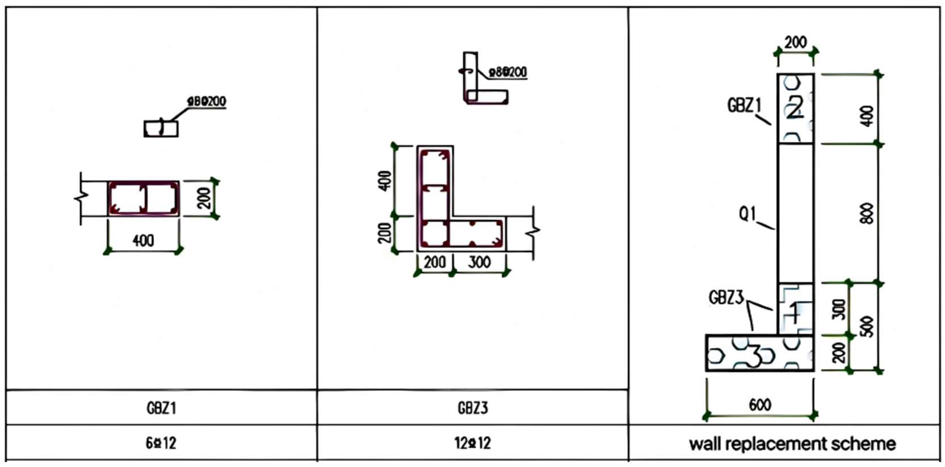
| Wall thickness (mm) and reinforcement | The wall thickness is 200 mm and the reinforcement is 8 @ 200 (double-layer bidirectional) | ||
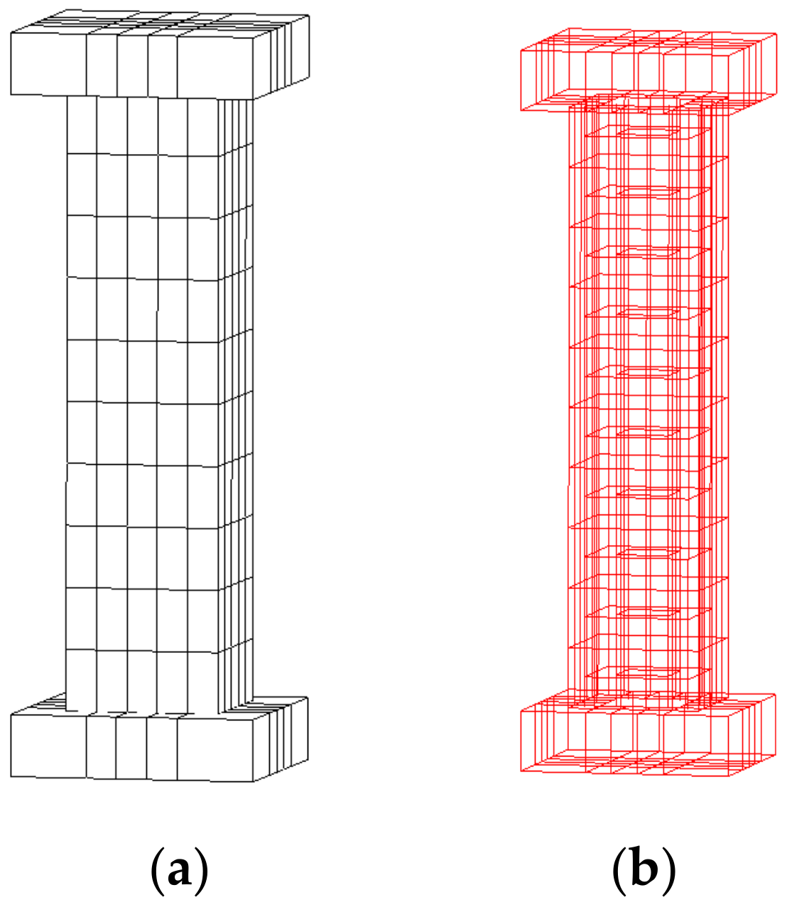
| Grid cell size (mm) | 600 × 200 × 295, 200 × 300 × 295, 200 × 100 × 295, 200 × 400 × 295 | ||
Disclaimer/Publisher’s Note: The statements, opinions and data contained in all publications are solely those of the individual author(s) and contributor(s) and not of MDPI and/or the editor(s). MDPI and/or the editor(s) disclaim responsibility for any injury to people or property resulting from any ideas, methods, instructions or products referred to in the content. |
© 2025 by the authors. Licensee MDPI, Basel, Switzerland. This article is an open access article distributed under the terms and conditions of the Creative Commons Attribution (CC BY) license (https://creativecommons.org/licenses/by/4.0/).
Share and Cite
Ke, N.; Liu, Y.; Yao, Z.; Deng, J.; Wei, X.; Wu, G.; Jia, Y. Using Nonlinear Simulation to Analyze the Bearing Performance and Engineering Application of Partial Strengthening and Replacement Composite Shear Walls Without Support Roof. Buildings 2025, 15, 4262. https://doi.org/10.3390/buildings15234262
Ke N, Liu Y, Yao Z, Deng J, Wei X, Wu G, Jia Y. Using Nonlinear Simulation to Analyze the Bearing Performance and Engineering Application of Partial Strengthening and Replacement Composite Shear Walls Without Support Roof. Buildings. 2025; 15(23):4262. https://doi.org/10.3390/buildings15234262
Chicago/Turabian StyleKe, Naiwen, Yuwei Liu, Zexin Yao, Jie Deng, Xianglan Wei, Guangyu Wu, and Yigang Jia. 2025. "Using Nonlinear Simulation to Analyze the Bearing Performance and Engineering Application of Partial Strengthening and Replacement Composite Shear Walls Without Support Roof" Buildings 15, no. 23: 4262. https://doi.org/10.3390/buildings15234262
APA StyleKe, N., Liu, Y., Yao, Z., Deng, J., Wei, X., Wu, G., & Jia, Y. (2025). Using Nonlinear Simulation to Analyze the Bearing Performance and Engineering Application of Partial Strengthening and Replacement Composite Shear Walls Without Support Roof. Buildings, 15(23), 4262. https://doi.org/10.3390/buildings15234262


