Article

The Deterioration of Concrete Based on the Experiments Under the Combined Effects of Freeze-Thaw Cycles, Carbonation Erosion and Sulfate Corrosion

1
School of Civil Engineering, Shenyang Jianzhu University, Shenyang 110168, China
2
College of Electrical Engineering, North China University of Science and Technology, Tangshan 063210, China
3
School of Management, Shenyang Jianzhu University, Shenyang 110168, China
*
Author to whom correspondence should be addressed.
Buildings 2025, 15(22), 4179; https://doi.org/10.3390/buildings15224179
Submission received: 31 August 2025 / Revised: 27 September 2025 / Accepted: 5 October 2025 / Published: 19 November 2025

Abstract

With the progress of human civilization and technology, the focus on civil engineering materials has shifted toward modern concrete materials. These materials are characterized by the incorporation of various admixtures and fibers. Therefore, it is essential to study their durability under diverse environmental conditions. Firstly, an experimental method is designed to investigate the combined effects of freeze–thaw cycles, carbonation erosion, and sulfate corrosion on concrete durability. Then, models for concrete deterioration are constructed based on the water–binder ratio, fly ash content, polypropylene fiber content, sulfate solution concentration, and compressive strength of concrete, which can reveal the interplays of freeze–thaw cycles, carbonation, and sulfate conditions. Meanwhile, an index-oriented adaptive differential evolution (IOADE) algorithm is proposed to obtain the optimal parameters for the deterioration models. Finally, data experiments demonstrate the reasonableness and efficacy of the proposed models.

1. Introduction

In the past, scholars have mainly focused on traditional concrete materials. However, the field of civil engineering materials has shifted towards modern concrete materials, which are characterized by the inclusion of admixtures and fibers. This progression aligns with the growing need for new concrete structures to have increased durability [1,2]. Taha et al. [3] studied the combined effects of basalt fibers and ground on the mechanical and durability properties. Additionally, the mechanical properties of concrete were evaluated through compressive strength and flexural properties. Harelimana et al. [4] investigated the effects of bonds between concrete and bamboo on the strength of concrete, which can achieve bonding that significantly affects the concrete strength. Currently, researchers in this field examine the mechanical and physical characteristics of concrete, typically considering single or dual factors. Therefore, there are some shortcomings in the study of concrete durability, particularly in understanding the combined effects of multiple factors on its longevity [5,6,7]. Yang et al. [8] studied the coupling effect on concrete durability, which the phase composition and microstructure attacked is revealed by the microstructure analysis techniques. Roja et al. [9] explored the role of mineral admixtures in enhancing the concrete strength and promised to develop environmentally friendly concrete.
Freeze–thaw cycles serve as a key evaluation index for concrete durability [10,11,12]. To study the modern concrete materials in freeze–thaw experiments, it is crucial to establish the damage equations, which can offer valuable insights into the durability index and structural reliability. Huang et al. [13] explored the impact of early freeze–thaw cycle damage on the self-healing capabilities of hydraulic concrete. Then, the mechanical model is established. Besides freeze–thaw cycles, carbonation erosion is also a crucial aspect when it comes to the durability of concrete [14,15,16,17]. For the vast geographic diversity of China, including coastal areas and the western Salt Lake region, the widespread presence of sulfates in soil and groundwater presents unique challenges to concrete durability. Therefore, the concrete structure is also subjected to sulfate corrosion, which leads to a more complex deterioration mechanism.
The durability of concrete is influenced by a complex interplay of various environmental factors. The durability of concrete has been the subject of extensive research [18,19,20,21]. In cold and particularly coastal regions, freeze–thaw cycles frequently combine synergistically with other environmental variables. Meanwhile, studies have been conducted on how freeze–thaw cycles and chloride affect the durability [22,23,24]. Jiang et al. [25] focused on the properties with an additional 20% fly ash. Wang et al. [26] explored the durability incorporating fly ash and silica fume under simultaneous freeze–thaw and sulfate corrosion. Considering the combined effects of freeze–thaw cycles and sulfate corrosion, Yang et al. [27] investigated the resistance of coarse recycled concrete aggregates, which contain low and high volumes of fly ash. Abd Elmoaty M et al. [28] examined the influence of using sulfate-contaminated aggregate on corrosion resistance. Despite these studies having achieved satisfactory results, research focused on the modern concrete under the combined action of the freeze–thaw cycle, carbonization erosion, and sulfate corrosion remains scarce.
The durabilities of modern concrete subjected to the combined effects of freeze–thaw cycles, carbonation erosion, and sulfate corrosion are investigated, which include the examination of external appearance damage, compressive strength, variations in weight, and the RDME. Based on the established theory of freeze–thaw damage, novel damage evolution models that encapsulate the influence of sulfate, carbonation, and freeze–thaw cycles are proposed. To enhance the practical application of the proposed models, the IOADE algorithm is incorporated to obtain the unknown parameters. Compared with the traditional fitting methods, the proposed approach has superior convergence capabilities. This study can offer valuable insights and reliable references for predicting the durability of modern concrete.

2. Materials and Experiments

In this part, the detailed information of raw materials for the P.O 42.5 cement and Class II fly ash is displayed firstly. Then, the mixing ratio of concrete specimens is introduced. And the fully mixed method for the raw materials is given. For the test methods, the experimental instruments, devices, test arrangement, and test requirements are detailed.

2.1. Raw Materials

The P.O 42.5 cement and Class II fly ash are used and the specifications are shown in Table 1. Meanwhile, the compositions are outlined in Table 2. For the aggregates, the natural fine aggregate consists of sand with particle sizes below 5 mm, and the natural coarse aggregate consists of crushed stone with particle sizes ranging from 5 to 31.5 mm. The local tap water is employed for the concrete mixtures. To simulate the process of sulfate corrosion, the anhydrous sodium sulfate with a purity of 99% is used in preparing the sulfate solutions. Meanwhile, a polycarboxylic acid-based superplasticizer and polypropylene fibers are added.

2.2. Concrete Mix Ratio

The mixing ratio of concrete specimens is shown in Table 3. The M45-30-10 label indicates the water-to-binder ratio and the fly ash content in the cementitious material, and the polypropylene fiber by volume of the concrete specimen is 0.45, 30%, and 1%, respectively. The test solutions are prepared from 3%, 5%, and 10% Na2SO4 solution. To make the raw materials fully mixed, an appropriate amount of admixture is added in the process of specimen making. Simultaneously, the sand ratio is set at 35% and the concrete unit weight is fixed at 2480 kg / m 3 . The specimens are naturally cured for 24 h prior to molding. Following the ASTM C666 standard, the specimens are placed in a curing chamber for 28 days before being set aside for further analysis.

2.3. Test Methods

2.3.1. Experimental Instruments and Devices

The instruments and devices used include the YES-2000B series digital display pressure tester, CCB-70A series concrete accelerated carbonation machine, KDR-V9 series rapid freeze–thaw test machine, NELD-DTV series dynamic elastic modulus tester, and LM-30 series electronic scale, as shown in Figure 1.

2.3.2. Test Arrangement

In an indoor environment, a single rapid freeze–thaw cycle is roughly equivalent to experiencing 12 cycles occurring naturally. Specifically in Northeast China, the typical annual occurrence of freeze–thaw cycles is approximately 120 [29]. Additionally, our studies have confirmed that the depth of carbonation achieved through 30 days of accelerated carbonization in the lab closely approximates the carbonation depth observed naturally over a period of 50 years [30]. Based on these findings, the test procedures are shown in Table 4.

2.3.3. Test Requirements

  • The compressive strength is evaluated to assess their performance. To minimize the impact of external factors on these measurements, each type of concrete is tested with three samples, and the average strength is determined from these results.
  • The carbonization test is performed under specific conditions, namely, a CO 2 concentration of 20%, a temperature maintained at 20 ± 2 °C, and a relative humidity of 70 ± 5% [31].
  • A freeze–thaw cycle occurs through freezing at −16 ± 2 °C and melting at 3 ± 2 °C. Every freeze–thaw cycle is finished within a time range of 2 to 4 h. The thawing period is at least 1/4 of the length of a freeze–thaw cycle.
Before presenting the results and discussion, the reasonable assumptions for the establishment of the concrete deterioration models should be given here. Firstly, the initial damage value is 0 before the actual freezing and thawing cycle test. Meanwhile, the damage value increases monotonically with the number of freezing and thawing cycles. Then, the coupling effects of parameters such as temperature fluctuation range and porosity are not considered.

3. Results and Discussion

The test results provide comprehensive investigations of the appearance damage, compressive strength, weight reduction, and RDME in various environmental conditions. The influences on the durability of concrete specimens are analyzed. Meanwhile, the durability degradation laws in the SF and SFC conditions are investigated.

3.1. Apparent Morphology

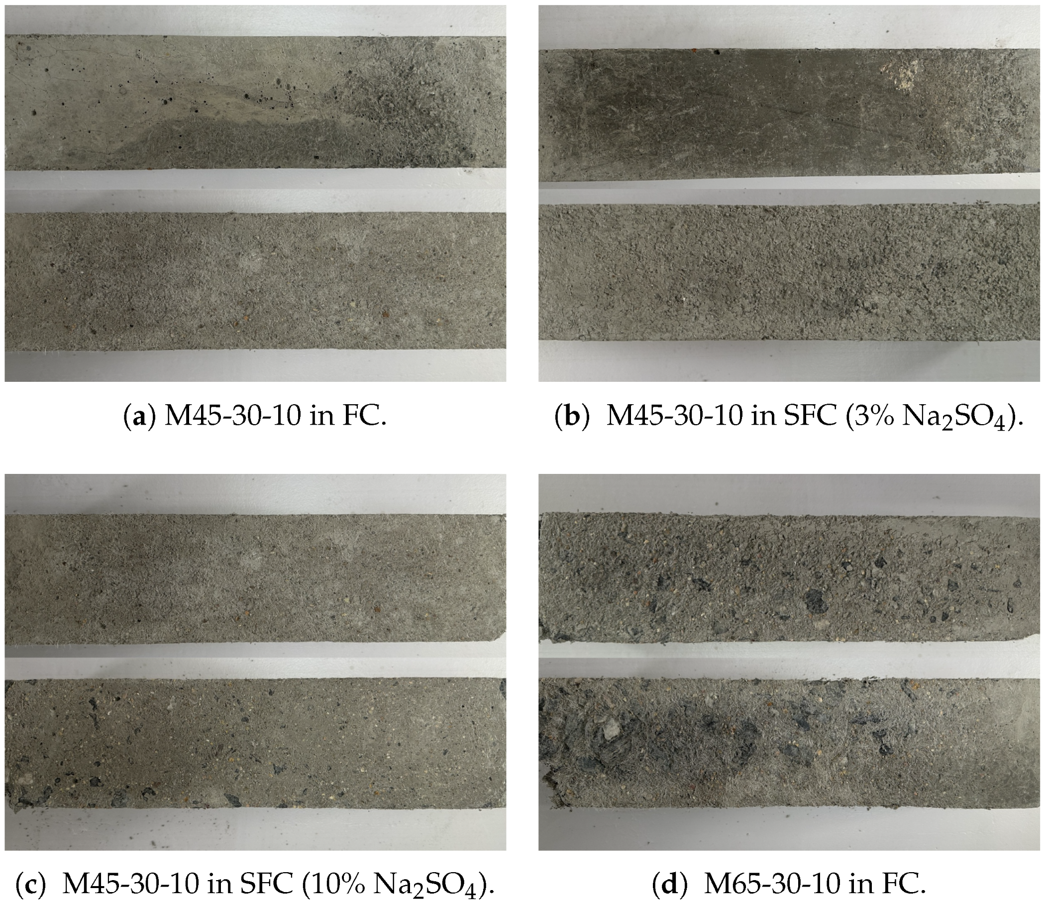
The test results indicate that the specimens with different mix ratios and Na2SO4 solution concentrations show significant differences in surface damage, as shown in Figure 2. The concrete specimens of N45-30-10 exhibit no significant damage after three great cycles under FC conditions. However, the aggregate is not exposed, as shown in Figure 2a. In 3% Na2SO4 solution, it has a relatively smooth surface with some color changes and minor defects after three great cycles under the SFC condition. Since there are physical damages from freeze–thaw cycles, the surface becomes rougher with more pits and flaws after five great cycles. Furthermore, the reaction of sulfate ions with the cement matrix components forms gypsum and expansive compounds, as shown in Figure 2b. After three great cycles in 10% Na2SO4 solution under the SFC condition, the surface exhibits a mottled appearance with many small pits and voids. After five great cycles, it exhibits a significant surface deterioration with larger aggregate particles being prominently exposed. Meanwhile, it shows dark spots and areas of color change on the surface, which is caused by the extensive microcracking and surface degradation due to sulfate corrosion, as shown in Figure 2c. The sand on the surface of concrete specimen N65-30-10 emerges and peels quickly under FC conditions. After five great cycles, the entire surface aggregate is exposed and damaged, as shown in Figure 2d.

3.2. Compressive Strength

During the curing phase, concrete specimens undergo a process of hardening and strength enhancement due to the long-term hydration of cement. The failure of concrete specimens typically involves the expansion and deepening of cracks within the concrete. The cracks initiate at the boundary and subsequently develop into small-scale cracks within the mortar itself [32]. Meanwhile, the microcracks widen and multiply with the increase in stress levels. Ultimately, the formation of through-joints causes the failure of concrete specimens.
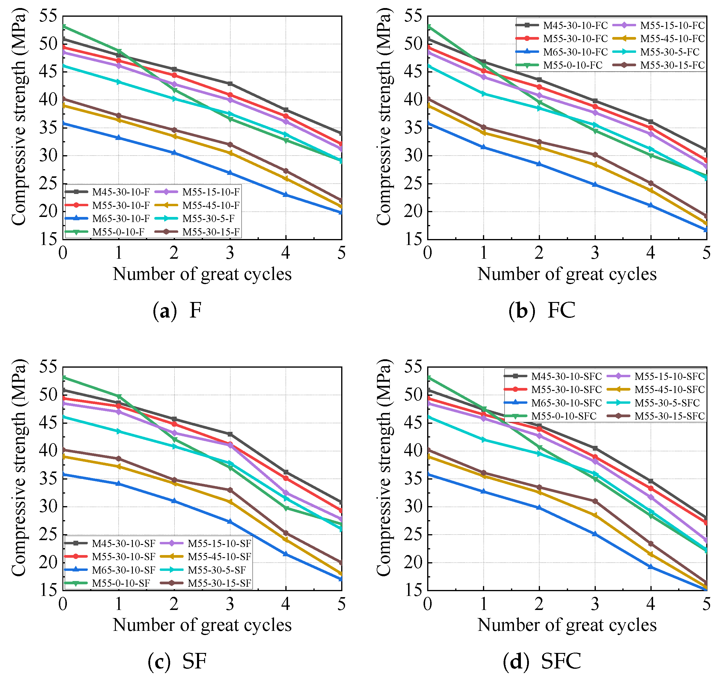
Under FC, SF, and SFC conditions, the compressive strength reduction follows a two-phase pattern. It contains a slow decline stage and an accelerated loss stage, which is closely tied to the evolution of damage mechanisms. In the initial freeze–thaw cycles, sulfate corrosion primarily acts on the concrete surface. Simultaneously, carbonation increases the structural density by forming calcium carbonate, which partially offsets the damage from the sulfate attack. In the SFC condition, the compressive strength decreases gradually during the first three cycles since the combined effects of surface sulfate corrosion and carbonation lead to a relatively balanced interaction between damage and density enhancement, as shown in Figure 3d. With more cycles, sulfate ions penetrate deeper into the concrete interior under the combined actions of freeze–thaw, carbonation, and sulfate corrosion, especially in the SFC condition. It reacts with hydration products to form expansive substances, such as ettringite and gypsum. These substances generate internal stress, initiating and propagating microcracks. As freeze–thaw damage accumulates and the volume of erosion products increases, the microcracks coalesce into macrocracks, which leads to a rapid drop in compressive strength. In Figure 3d, it accelerates degradation and becomes prominent after three cycles.
Figure 3a shows a more uniform decline in strength compared to FC, SF, and SFC. In Figure 3b, the introduction of carbonation and other factors leads to a steeper decline in the later stages than Figure 3c,d involve more complex chemo-mechanical interactions. Notably, the presence of sulfate in SF and SFC can decelerate strength loss compared to FC before three cycles. Since the sulfate corrosion initially affects the surface, the resulting products may temporarily inhibit some freeze–thaw damage. However, the combined corrosion in SFC causes the most severe degradation after 3–5 cycles, as the synergistic effect of multiple factors accelerates crack formation and propagation.
As observed in the SFC condition, specimens with a higher water-to-binder ratio exhibit lower compressive strength after five cycles compared to those with a lower ratio. A higher water-to-binder ratio results in more initial porosity, providing easier pathways for corrosive ions and facilitating freeze–thaw damage. The inclusion of suitable amounts of fly ash and fiber can mitigate the damage under combined actions. Fly ash refines the pore structure and reacts with calcium hydroxide to form additional C-S-H gel, which can enhance the matrix density. Fibers can fill in cracks, prevent the expansion of cracks, and enhance the toughness and resistance to repeated damage of concrete. After three cycles, the compressive strength reduction extent becomes the greatest among the conditions. It highlights that the combined freeze–thaw and carbonation leads to faster damage accumulation in the initial cycles, which is different from the early-stage sulfate deceleration effect in the SF and SFC conditions. After five cycles, the compressive strength in the SFC condition shows the most significant loss, which reveals the long-term synergistic damage of freeze–thaw, carbonation, and sulfate corrosion. Meanwhile, the accelerated crack growth in the late stage dominates the strength degradation.
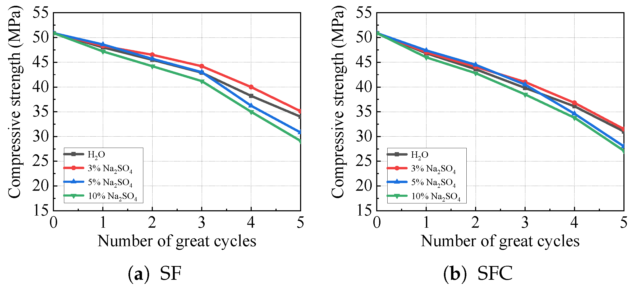
In the SF condition, the compressive strength of the M45-30-10 specimens decreases by 33.2%, 31.02%, 39.49%, and 42.83% in the H2O, 3%, 5%, and 10% Na2SO4 solutions after five great cycles, as shown in Figure 4. Meanwhile, the decreases are 39.1%, 38.11%, 44.99%, and 46.76% in the SFC condition, respectively. The most significant loss of concrete specimens in compressive strength is observed in the condition of 10% Na2SO4 solution and the least loss in the condition of 3% Na2SO4 solution. Initially, the strength degradation in H2O solution is almost comparable to that in the 3% and 5% Na2SO4 solutions. However, the compressive strength in the 5% Na2SO4 solution deteriorates significantly after three great cycles, which means the damage rate in the 5% Na2SO4 solution is faster than that of the H2O solution. Thus, it leads to a greater loss in compressive strength compared to that in H2O solution.

3.3. Weight Change

Weight changes in the concrete specimens can be observed during the process of damage. To assess the frost resistance, it is essential to measure and analyze the weight variations throughout the great cycles.
Δ W = W 0 W n W 0 × 100
where Δ W represents the rate of weight reduction in the concrete sample following each great cycle, W 0 denotes the initial weight, and W n signifies the weight after the completion of the nth great cycle.
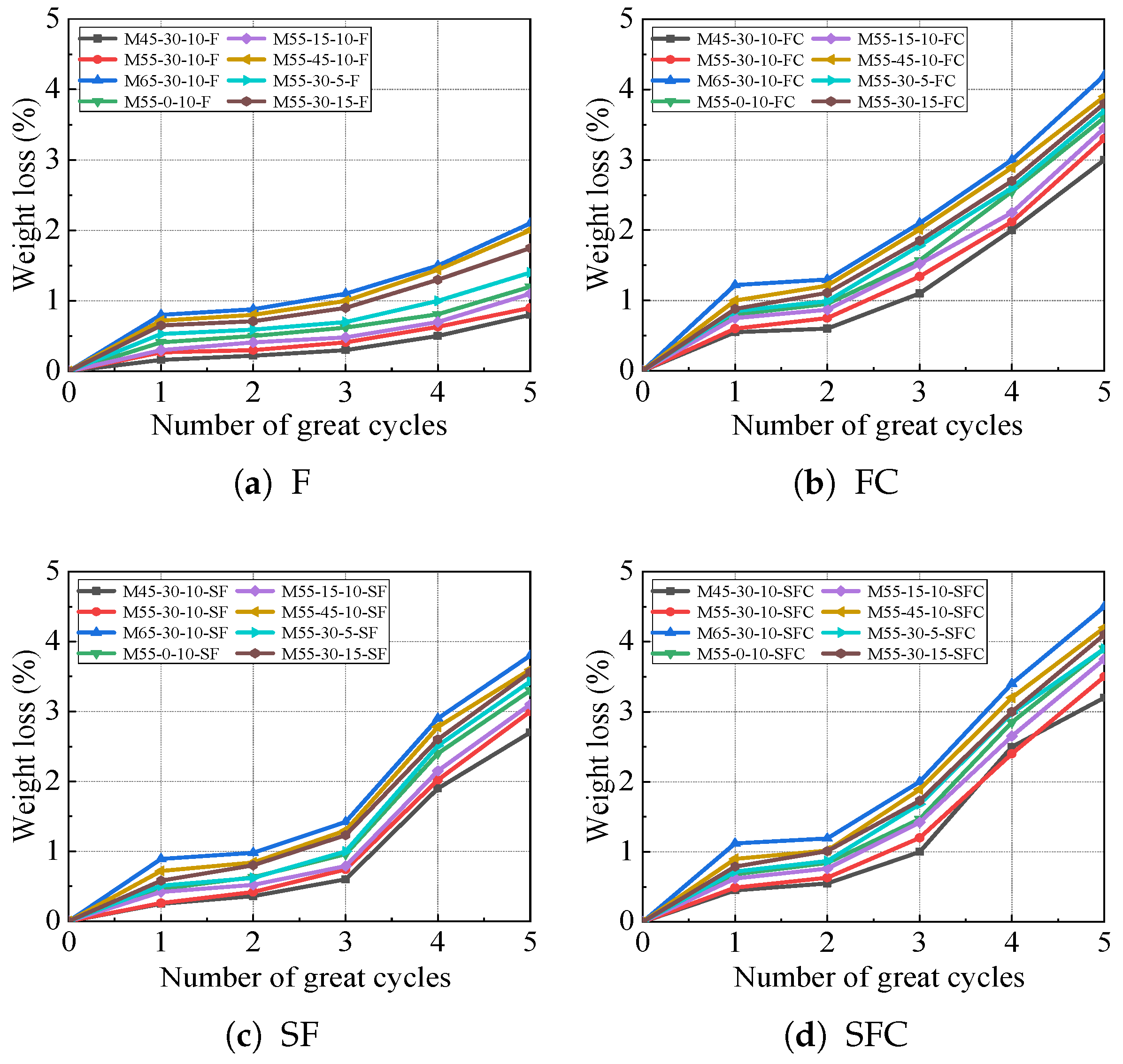
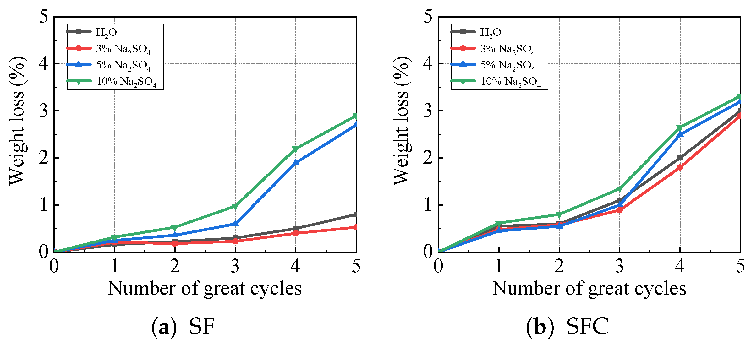
Figure 5 shows the weight loss of concrete specimens across the F, FC, SF, and SFC conditions. Figure 5 reveals that weight loss increases with the number of great cycles, which means freeze–thaw keeps damaging the concrete structure over time. Compared with FC, SF, and SFC conditions, weight loss of the F condition is relatively slower than in conditions with sulfate, as shown in Figure 5a. Since the main damage is just freeze–thaw cycling, the water in pores freezes without sulfate, which expands and causes cracking without the extra crystallization pressure from sulfate salts. In contrast, weight loss is faster for FC, SF, and SFC conditions, as shown in Figure 5b–d. Firstly, sulfate crystallization fills small pores, temporarily reducing weight loss. As cycles increase, sulfate solution seeps deeper. The repeated crystallization in pores creates pressure and expedites cracking and spalling, which leads to accelerated weight loss later.
Among sulfate-containing conditions of FC, SF, and SFC, some differences exist. In the FC condition, weight loss is the most significant in the early stages after three great cycles, as shown in Figure 5b. It shows that the combination of freeze–thaw and continuous sulfate exposure causes rapid initial damage. For the SFC condition, weight loss becomes the highest after five great cycles, as shown in Figure 5d. It indicates that the specific SFC condition leads to cumulative damage, which can surpass the FC condition over longer cycles.
Moreover, Figure 5 shows the three-stage weight loss pattern, that is, initial rapid loss, stable loss, and accelerated loss. In the initial rapid loss stage, early damage slightly reduces strength. In the stable loss stage, pore refinement from sulfate crystallization temporarily stabilizes strength. In the accelerated loss stage, severe cracking from cyclic crystallization and freeze–thaw causes a sharp drop in strength. Mechanistically, the ice expansion in pores is slow for the F condition and weight loss is gradual. For FC, SF, and SFC conditions, damage is accelerated by sulfate crystallization pressure. Early pore filling delays damage, but long-term cycling brings intense internal stress, which can lead to faster spalling and weight loss. Meanwhile, the most damaging condition is shifted by the cycle count.
Figure 6 illustrates the weight reduction in the M45-30-10 concrete specimens under the different sulfate concentrations. In the SF condition, the weight reduction rates of concrete specimens in H2O solution and 3%, 5%, and 10% Na2SO4 solutions are 0.8% and 0.53%, 2.7%, and 2.9% after five great cycles, respectively. In the SFC condition, the rates are 3%, 2.9%, 3.2%, and 3.32%, respectively. The highest and the least weight reduction in concrete specimens occurs in the 10% and 3% Na2SO4 solution. In the SF condition, concrete specimens show minimal weight reduction in H2O and 3% Na2SO4 solutions. However, the weight reduction escalates with an increased number of great cycles in 5% and 10% Na2SO4 solutions, especially after the third great cycle. Therefore, it can be achieved that the higher concentrations of sulfate solutions have a considerable impact, particularly in freeze–thaw and carbonation environments.

3.4. Relative Dynamic Modulus of Elasticity (RDME)

The RDME is widely used to evaluate concrete performance. The interior compactness is reflected by this indicator, which is highly responsive to any changes caused by continuous deterioration [33]. The RDME is calculated by the following formula.
v = L t
E d = ( 1 + μ ) ( 1 2 μ ) 1 μ ρ v 2
E n = v n 2 / v 0 2
where E d refers to the dynamic elastic modulus, E n signifies the RDME following n great cycles, v represents the wave speed, L is the length of specimen, t shows the propagation time, μ is Poisson’s ratio, ρ is the density of the medium, v n is the wave speed after experiencing freezing and thawing n times, and v 0 is the initial wave speed.
It can be learned from Figure 7 that the results of the RDME are consistent with the observed trends in weight reduction, which can provide a complementary measure of the internal damage sustained by the concrete specimens. Under the F, FC, SF, and SFC conditions, the RDME exhibits a characteristic two-phase deterioration pattern, which is an initial phase of slow decline followed by a subsequent phase of rapid decline.
In the early stages of exposure, the degradation mechanisms primarily affect the surface and near-surface paste. In the SF and SFC conditions, the initial precipitation of sulfate salts can temporarily densify the pore structure, slightly mitigating the rate of RDME loss. Concurrently, carbonation in the FC and SFC conditions contributes to the formation of additional, but potentially less robust, C-S-H gels and calcite, leading to a gradual, yet steady, decrease in the RDME. This phase represents the material’s resistance to initial chemical and physical attack before significant microcracking occurs.
However, with repeated great cycles, the damage mechanism transitions. The continuous crystallization pressure from sulfates, combined with the expansive stresses of freeze–thaw cycles, initiates and propagates microcracks within the concrete matrix. This internal cracking severely compromises the structural integrity of the material, which is directly reflected in the RDME. As the microcracks connect and multiply, the concrete’s ability to transmit elastic waves is reduced drastically, leading to the observed sharp drop in the RDME. The most severe deterioration is unequivocally observed in the SFC condition, which combines all three degradation processes. It should be noted that the RDME of the M65-30-10 specimens in the 5% Na2SO4 solution is reduced to only 0.5 after five SFC great cycles, indicating that the concrete has lost half of its original dynamic stiffness. It underscores the profoundly synergistic and destructive nature of combined sulfate attack, carbonation, and freeze–thaw cycling.
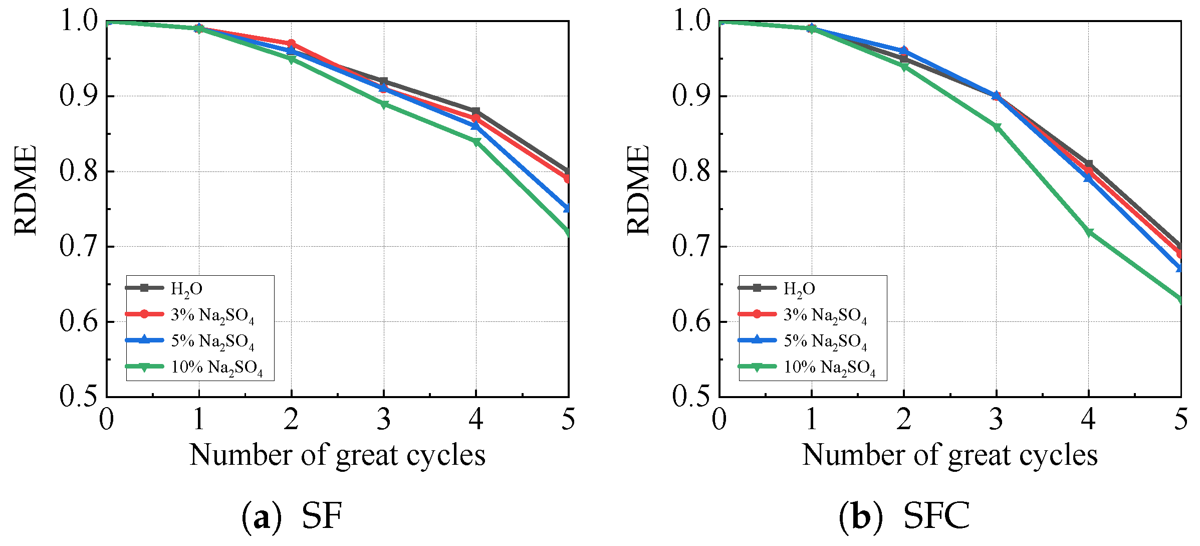
Figure 8 illustrates the RDME of the M45-30-10 concrete specimens in Na2SO4 solutions of varying concentrations under SF and SFC conditions. Obviously, the RDME of concrete specimens decreases as the number of great cycles rises. It means that the concrete’s elastic properties gradually degrade along with sulfate attack. Compared with the SF and SFC conditions, the reduction in the RDME is less pronounced in the SF condition. The decline in the RDME is relatively gradual even in the most aggressive sulfate environment of 10% Na2SO4 solution. It implies that sulfate attack alone causes slower degradation of the dynamic modulus of elasticity without the coupling of carbonation. In contrast, the reduction in the RDME is more significant in the SFC condition, which highlights that the coupling of sulfate attack and carbonation intensifies the damage to concrete. Carbonation can alter the concrete’s pore structure and chemical composition, such as converting calcium hydroxide to calcium carbonate. Therefore, the concrete specimens are more susceptible to sulfate-induced damage, which accelerates the loss of elastic properties.
In SF and SFC conditions, the RDME reduction in 3% and 5% Na2SO4 solutions and H2O is relatively consistent. The rate of sulfate infiltration and crystallization is balanced enough for the degradation mechanism to progress at a similar pace. However, the decline in the RDME is most pronounced in the 10% Na2SO4 solution in SF and SFC conditions. Higher sulfate concentration means more sulfate ions infiltrate the concrete, leading to greater crystallization pressure in pores, which damages the concrete structure. And more intense chemical reactions further degrade the concrete’s elasticity. In the SFC condition, the combination of intense sulfate attack and carbonation makes the degradation even faster, resulting in the steepest drop in the RDME. After five great cycles in the SFC condition, the RDME values for different solutions are 0.7 for H2O, 0.69 for 3% Na2SO4, 0.67 for 5% Na2SO4, and 0.63 for 10% Na2SO4. The quantification shows that the RDME decreases more significantly in the SFC condition as the sulfate concentration increases.
Mechanistically, the damage of concrete is driven by freeze–thaw cycling and sulfate crystallization pressure in the SF condition. The concrete’s resistance to elastic deformation declines as cycles and sulfate attack progress. However, the degradation rate is lower without carbonation. In the SFC condition, carbonation modifies the concrete matrix, which can reduce alkalinity and change the pore structure. It makes the concrete more vulnerable to sulfate attack—sulfate ions penetrate more easily, and sulfate-related reactions occur more readily, thereby leading to a faster loss of the dynamic modulus of elasticity. In summary, it shows that both the coupling of sulfate attack with carbonation and increasing sulfate concentration accelerate the degradation of concrete’s dynamic modulus of elasticity under cyclic actions.

4. Establishment of the Damage Model and Application of the IOADE Algorithm

4.1. Establishment of the Damage Model

When exposed to freeze–thaw, carbonation, and sulfate corrosion conditions, concrete specimens are more prone to developing erosion-induced cracks, which can affect the freeze resistance. To conduct an in-depth study of its principles, the durability of concrete is investigated from four aspects, the appearance loss, compressive strength, mass loss, and relative dynamic elastic modulus. The appearance loss of concrete is shown in Figure 2. The compressive strength of concrete is presented in Figure 3 and Figure 4. The mass loss of concrete is illustrated in Figure 5 and Figure 6, and the relative dynamic elastic modulus is depicted in Figure 7 and Figure 8. The results show that the durability of concrete specimens is highly responsive to the water-to-binder ratio, fly ash content, polypropylene fiber content, and Na2SO4 solution concentration when impacted by the combined effects of freeze–thaw cycles, carbonation erosion, and sulfate corrosion.
In this paper, the variation in weight reduction and the RDME of specimens are analyzed. Based on the analysis of the damage law for different mix proportions and sulfate concentrations, the damage models are established for the concrete specimens. Under the SF and SFC conditions, the reduction in the weight and RDME of concrete samples is influenced by several factors, as outlined in Equations (5) and (6).
W n = α w / b α f a α f b α n α C s + k i
E n = β w / b β f a β f b β C s E 0 e γ n f c u + k j
where W n denotes the concrete’s weight reduction during the nth significant cycle. The variables α w / b , α f a , α f b , α n , and α C s are fitting parameters linked to the water-to-binder ratio, the content of fly ash, the proportion of polypropylene fibers, the count of significant cycles, and the sulfate concentration related to weight reduction. The parameter k i functions as a correction factor. E n signifies the RDME at the nth significant cycle, while E 0 , set to 1, represents the initial RDME. Correspondingly, β w / b , β f a , β f b , and β C s account for the fitting parameters associated with the same variables concerning the RDME. The variable n indicates the number of significant cycles, γ refers to the attenuation parameter, and f c u denotes the compressive strength under standard conditions for 28 days.
Under the SF and SFC conditions for weight reduction,
α w / b = a i ( w / b ) 2 + b i ( w / b ) + c i
α f a = d i l n ( f a ) + e i
α f b = f i f b + g i
α n = h i n
α C s = l i C s + m i
Meanwhile, in the conditions of SF and SFC for the RDME,
γ = h j
where w / b , f a , f b , and C s are the water-to-binder ratio, fly ash content, polypropylene fiber content, and sulfate concentration of concrete specimens, respectively.

4.2. Application of the IOADE Algorithm and Model Verification

The weight reduction and RDME subject to SF and SFC conditions are formulated as Equations (5) and (6). However, the parameter determination in Equations (5) and (6) remains a challenge. Traditionally, fitting methods are applied to ascertain these parameters [34,35]. To assess the influence of various factors, an evolution algorithm is adopted. Differential evolution (DE) is a well regarded method for global optimization that is valued for its simplicity and robustness. It has been widely applied in numerous optimization scenarios. The DE algorithm includes the key steps outlined below.
(1) Mutation. Two unique individuals are selected, and the difference between them is computed. Then, the difference is merged with the individual undergoing mutation.
x ˜ i ( g + 1 ) = x r 1 ( g ) + F · ( x r 2 ( g ) x r 3 ( g ) )
where F ranges from 0 to 1, and x ˜ i ( g + 1 ) represents the mutant intermediate in the ( g + 1 ) -th generation. x i ( g ) is the i-th individual in the g-th generation, where i takes values from 1 to P, and P is the size of the population. x r 1 ( g ) , x r 2 ( g ) , and x r 3 ( g ) are individuals picked from the g-th generation. The indices r 1 , r 2 , and r 3 are within the set { 1 , 2 , , P } , and they are all distinct from each other and also different from i.
(2) Crossover. To ensure x ˜ i ( g + 1 ) is passed to the next generation, a crossover operation is performed between the gth generation population x i ( g ) and its mutation intermediates x ˜ i ( g + 1 ) . This process entails cross-individual operation.
x ˜ j , i ( g + 1 ) , r a n d ( 0 , 1 ) C R o r j = j r a n d x j , i ( g ) , o t h e r w i s e
where x ˜ j , i ( g + 1 ) represents the individual x i ( g ) with the jth gene modified. C R is the probability of crossover, and j r a n d is an integer picked at random from the range of 1 to D, where D represents the overall number of genes.
(3) Selection. In this stage, the greedy algorithm selects the optimal individuals. This approach ensures that the individuals progressively approximate the target objective more closely.
x ( g + 1 ) = x ˜ ( g + 1 ) , f ( x ˜ ( g + 1 ) ) f ( x ( g ) ) x ( g ) , o t h e r w i s e
where f ( · ) represents the objective function and x ( g + 1 ) denotes the chosen individual in the ( g + 1 ) -th generation.
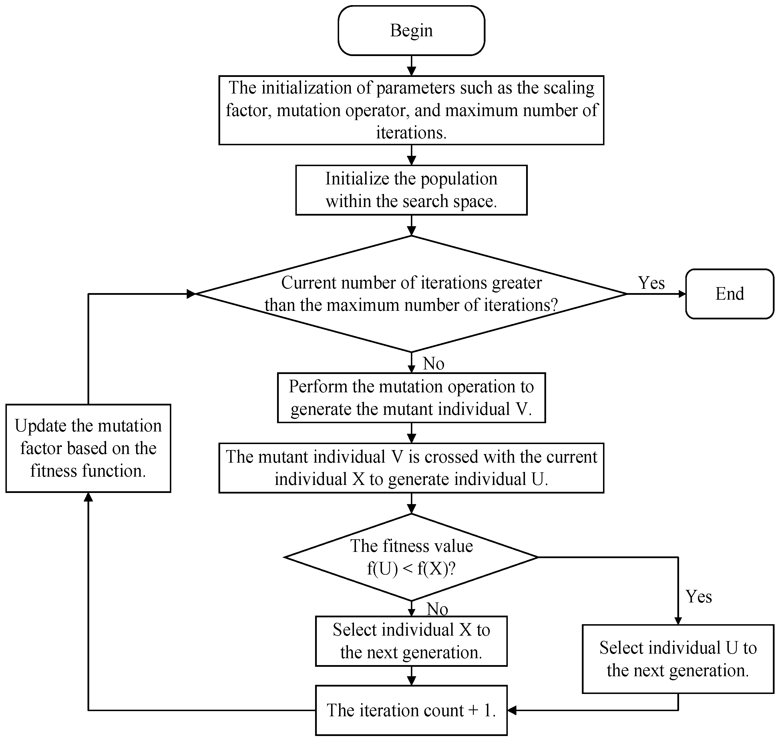
Equation (13) suggests that the scaling factor F in the DE algorithm is typically set based on empirical judgment, which often leads to suboptimal computation times [36]. To overcome this disadvantage, an IOADE algorithm is proposed in this paper, as shown in Figure 9. This approach allows for the dynamic updating of the scaling factor F. The updating mechanism is outlined as follows.
F = F 0 × 2 λ
λ = e 1 G m G m + 1 G × e l o g ( Δ J )
where F 0 [ 0 , 0.5 ] is a constant, λ is the mutation operator, G m is the maximum generation, G is the current generation, and Δ J is the objective function difference between two generations.
From Equations (16) and () one can learn that the suggested indicator-based adaptive scaling factor F has the capacity to be adjusted on-the-fly in accordance with the iteration count and the divergence between two consecutive generations. This adjustment is capable of boosting the convergence performance during the optimization procedure. The objective function is formulated as follows.
J ( Ψ * , w / b , f a , f b , n , C s , W n ) = min | | W n ^ ( Ψ * ) W n | | 2 s . t . Ψ m i n * Ψ * Ψ m a x *
where Ψ * = [ a i , b i , c i , d i , e i , f i , g i , h i , k i , l i , m i ] is a parameter vector in Equation (5). The index i corresponds to the conditions of SF and SFC, taking on the values i = 1 and i = 2 , respectively.
Regarding the unknown parameters in Equation (6), Equation (18) can be formulated as follows.
J ( Φ * , w / b , f a , f b , n , C s , f c u , E n ) = min | | E n ^ ( Φ * ) E n | | 2 s . t . Φ m i n * Φ * Φ m a x *
where Φ * = [ a j , b j , c j , d j , e j , f j , g j , h j , k j , l j , m j ] is a parameter vector in Equation (6). The variable j stands for the conditions of SF and SFC, with j taking the values of 1 and 2, respectively.
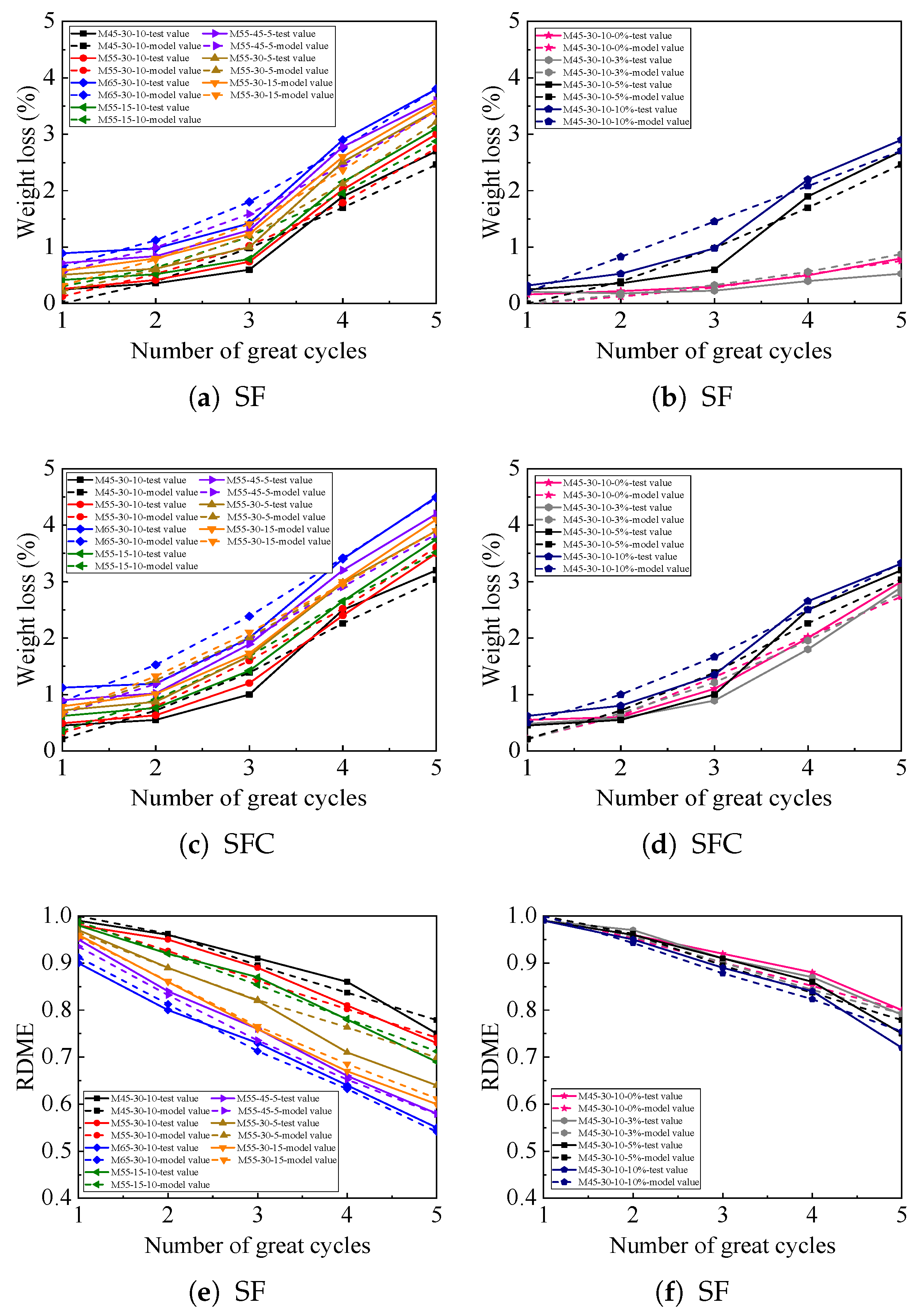
The IOADE algorithm is applied to the objective functions of Equations (18) and (19) so that the parameters in Equations (5) and (6) can be achieved, and the results detailed are shown in Table 5. Figure 10 offers a detailed comparison between the damage model predictions and true values for the different conditions and the accuracy of models is quantitatively assessed by the R 2 , MAE, and RMSE. Compared with the algorithms of DE and adaptive differential evolution (ADE) [37], the proposed IOADE algorithm has a high degree of correlation between the proposed models and the true values, as shown in Table 6 and Table 7. The accuracy and reliability of the proposed models confirm the potential applicability of the IOADE algorithm to a wide range of other complex systems and scenarios. The proposed IOADE algorithm extends the specific case of SF and SFC conditions, opening up new avenues for research and application in prediction and optimization fields.

5. Conclusions

This paper explores the cumulative impact of freeze–thaw cycles, carbonation erosion, and sulfate corrosion on the durability of concrete. In terms of concrete degradation under these conditions, several key findings emerge, which can be summarized as follows.
  • An experimental method has been designed in this paper, which can study the combined effects of freeze–thaw cycles, carbonation erosion, and sulfate corrosion on concrete durability.
  • Models for concrete deterioration have been constructed based on the water–binder ratio, fly ash content, polypropylene fiber content, sulfate solution concentration, and compressive strength of concrete, and the interplays of freeze–thaw cycles, carbonation, and sulfate conditions have been obtained.
  • To improve the accuracy of the damage evolution models, the IOADE algorithm has been proposed. Meanwhile, the excellent convergence of the proposed IOADE algorithm has been compared with the algorithms of DE and ADE by the R 2 , MAE, and RMSE.

Author Contributions

Conceptualization, X.C.; Methodology, Q.Y. and J.L.; Software, Q.Y. and Z.W.; Validation, Q.Y.; Formal analysis, Z.W.; Investigation, J.L.; Data curation, J.L.; Writing—original draft, Q.Y.; Writing—review & editing, Q.Y. and Z.W.; Supervision, X.C.; Funding acquisition, Z.W. All authors have read and agreed to the published version of the manuscript.

Funding

This research was funded by the Open Fund of the National Key Laboratory of Intelligent Optimization Manufacturing in Mining and Metallurgy Process grant number BGRIMM-KZSKL-2024-11.

Data Availability Statement

The data presented in this study are available on request from the corresponding author.

Acknowledgments

The authors appreciate the financial assistance from the Open Fund of the National Key Laboratory of Intelligent Optimization Manufacturing in Mining and Metallurgy Process (BGRIMM-KZSKL-2024-11).

Conflicts of Interest

The authors declare no conflicts of interest.

References

  1. Wang, R.J.; Hu, Z.Y.; Li, Y.; Wang, K.; Zhang, H. Review on the deterioration and approaches to enhance the durability of concrete in the freeze-thaw environment. Constr. Build. Mater. 2022, 321, 126371. [Google Scholar] [CrossRef]
  2. Zhang, R.L.; Zhang, X.P.; Xue, Y.J.; Wang, X.P.; Xiao, P.Z.; Song, Y. Research on the durability degradation mechanism of early-age concrete and life prediction model under freeze-thaw-salt erosion coupling effect. Structures 2025, 71, 107986. [Google Scholar] [CrossRef]
  3. Taha, A.; Alnahhal, W. Synergistic effects of recycled concrete powder, GGBFS, and basalt fibers on mechanical and durability performance of recycled aggregate concrete. Structures 2025, 71, 108058. [Google Scholar] [CrossRef]
  4. Harelimana, V.; Zhu, J.A.; Yuan, J.P.; Uwitonze, C. Investigating the bamboo as alternative partial replacement of steel bars in concrete reinforcement members. Struct. Des. Tall Spec. Build. 2022, 31, e1921. [Google Scholar] [CrossRef]
  5. Ehsan, H.; Behnam, M. Corrosion performance and strain behavior of reinforced concrete: Effect of natural pozzolan as partial substitute for microsilica in concrete mixtures. Structures 2025, 79, 109397. [Google Scholar] [CrossRef]
  6. Xiao, Q.H.; Cao, Z.Y.; Guan, X.; Li, Q.; Liu, X.L. Damage to recycled concrete with different aggregate substitution rates from the coupled action of freeze-thaw cycles and sulfate attack. Constr. Build. Mater. 2019, 221, 74–83. [Google Scholar] [CrossRef]
  7. Xiao, Q.H.; Li, Q.; Cao, Z.Y.; Tian, W.Y. The deterioration law of recycled concrete under the combined effects of freeze-thaw and sulfate attack. Constr. Build. Mater. 2019, 200, 344–355. [Google Scholar] [CrossRef]
  8. Yang, Q.T.; Liu, M.; Li, J.X.; Chen, X. Study on the degradation models based on the experiments considering the coupling effect of freeze-thaw and carbonation. Structures 2024, 64, 106659. [Google Scholar] [CrossRef]
  9. Roja, S.Y.; Yamini Roja, S.; Murali, K.; Shanthi, V.M. Enhancing Concrete Performance with Waste Foundry Sand Using Ternary Blended Mixes of Ordinary Portland Cement, Silica Fume, and Ground Granulated Blast Furnace Slag. Struct. Des. Tall Spec. Build. 2024, 33, e2180. [Google Scholar]
  10. Feng, Q.; Jin, J.; Zhang, S.; Liu, W.W.; Yang, X.X.; Li, W.T. Study on a damage model and uniaxial compression simulation method of frozen-thawed rock. Rock Mech. Rock Eng. 2022, 55, 187–211. [Google Scholar]
  11. Zhang, J.H.; Li, J.; Yun, H.; Long, J.Z.; Zhu, Q.X.; Guan, Z.G. Durability of new-to-old concrete interface under coupling action of freeze-thaw cycle and chloride salt erosion. Structures 2024, 70, 107867. [Google Scholar] [CrossRef]
  12. Chen, S.; Wang, Y.J.; Liu, Y.; Zhao, M.D. Mechanical properties, pore structure and freeze-thaw resistance of recycled aggregate concrete based on ash of mushroom and corn straw. Structures 2024, 68, 107167. [Google Scholar] [CrossRef]
  13. Huang, Y.Y.; Zhuang, W.; Li, Z.P.; Yu, Z.Y.; Shao, C.Y. The effect of early-age freeze-thaw cycle damage on hydraulic concrete self-healing. Mech. Time-Depend. Mater. 2023, 27, 529–542. [Google Scholar] [CrossRef]
  14. Liu, P.; Yu, Z.W.; Chen, Y. Carbonation depth model and carbonated acceleration rate of concrete under different environment. Cem. Concr. Compos. 2020, 114, 103736. [Google Scholar] [CrossRef]
  15. Xu, R.T.; Liang, Y.; Ning, F.; Chen, Z.P. The effect of NaHCO3 accelerated carbonation method on the early mechanical properties of recycled aggregate concrete. Structures 2024, 70, 107647. [Google Scholar] [CrossRef]
  16. Feng, M.J.; Li, M.; Qu, H.H.; Tian, D.J.; Lu, M.J.; Gui, T.T.; Li, G. Degradation mechanism and evaluation of the carbonation resistance of concrete after high-temperature exposure. Structures 2023, 58, 105621. [Google Scholar] [CrossRef]
  17. Bekdas, G.; Yucel, M.; Nigdeli, S.M. Generation of eco-friendly design for post-tensioned axially symmetric reinforced concrete cylindrical walls by minimizing of CO2 emission. Struct. Des. Tall Spec. Build. 2022, 31, e1948. [Google Scholar] [CrossRef]
  18. Qiao, Y.; Sun, W.; Jiang, J. Damage process of concrete subjected to coupling fatigue load and free/thaw cycles. Constr. Build. Mater. 2015, 93, 806–811. [Google Scholar] [CrossRef]
  19. Suzuki, T.; Ogata, H.; Takada, R.; Aoki, M.; Ohtsu, M. Use of acoustic emission and X-ray computed tomography for damage evaluation of freezethawed concrete. Constr. Build. Mater. 2010, 24, 2347–2352. [Google Scholar] [CrossRef]
  20. Tangtermsirikul, S.; Khunthongkeaw, J.; Leelawat, T. A study on carbonation depth prediction for fly ash concrete. Constr. Build. Mater. 2006, 20, 744–753. [Google Scholar] [CrossRef]
  21. Wang, Y.; An, M.Z.; Yu, Z.R.; Han, S.; Ji, W.Y. Durability of reactive powder concrete under chloride-salt freeze-thaw cycling. Mater. Struct. 2017, 50, 18. [Google Scholar]
  22. Kessler, S.; Thiel, C.; Grosse, C.U.; Gehlen, C. Effect of freeze-thaw damage on chloride ingress into concrete. Mater. Struct. 2017, 50, 121. [Google Scholar]
  23. Mu, R.; Miao, C.; Luo, X.; Sun, W. Interaction between loading, freeze-thaw cycles, and chloride salt attack of concrete with and without steel fiber reinforcement. Cem. Concr. Res. 2002, 32, 1061–1066. [Google Scholar] [CrossRef]
  24. Liang, M.T.; Wang, K.L.; Liang, C.H. Service life prediction of reinforced concrete structure. Cem. Concr. Res. 1999, 29, 1411–1418. [Google Scholar] [CrossRef]
  25. Jiang, L.; Niu, D.T.; Yuan, L.D.; Fei, Q.N. Durability of concrete under sulfate attack exposed to freeze-thaw cycles. Cold Reg. Sci. Technol. 2015, 112, 112–117. [Google Scholar]
  26. Wang, D.Z.; Zhou, X.M.; Meng, Y.F.; Chen, Z. Durability of concrete containing fly ash and silica fume against combined freezing-thawing and sulfate attack. Constr. Build. Mater. 2017, 147, 398–406. [Google Scholar] [CrossRef]
  27. Li, Y.; Wang, R.J.; Li, S.Y.; Zhao, Y.; Qin, Y. Resistance of recycled aggregate concrete containing low- and high-volume fly ash against the combined action of freeze-thaw cycles and sulfate attack. Constr. Build. Mater. 2018, 166, 23–34. [Google Scholar]
  28. Elmoaty, M.A.; Elmoaty, A. Four-years carbonation and chloride induced steel corrosion of sulfate-contaminated aggregates concrete. Constr. Build. Mater. 2018, 163, 539–556. [Google Scholar]
  29. Oliveira, M.B.; Vazquez, E. The influence of restained moisture in Aggregates from recycling on tbe properties of new hardened concrete. Waste Manag. 1996, 16, 113–117. [Google Scholar]
  30. Sun, B.; Mao, S.Y.; Wang, J.X.; Di, X.T.; Ren, R.H. Experimental study on correlation between natural carbonation and accelerated carbonation of long-term observation concrete specimens. Build Struct. 2019, 49, 111–114. [Google Scholar]
  31. GB/T50082-2024; Standard for Test Methods of Long-Term Performance and Durability of Ordinary Concrete. China Architecture & Building Press: Beijing, China, 2024.
  32. Wang, J.B.; Niu, D.T.; He, H. Frost durability and stress-strain relationship of lining shotcrete in cold environment. Constr. Build. Mater. 2019, 198, 58–69. [Google Scholar] [CrossRef]
  33. Wang, J.B.; Niu, D.T. Influence of freeze-thaw cycles and sulfate corrosion resistance on shotcrete with and without steel fiber. Constr. Build. Mater. 2016, 122, 628–636. [Google Scholar] [CrossRef]
  34. Ortega, J.J.; Ruiz, G.; Yu, R.N.C.; Afanador-Garca, N.; Tarifa, M.; Poveda, E.; Zhang, X.; Evangelista, F., Jr. Number of tests and corresponding error in concrete fatigue. Int. J. Fatigue 2018, 116, 210–219. [Google Scholar] [CrossRef]
  35. Nguyen, M.H.; Nguyen, T.A.; Ly, H.B. Ensemble XGBoost schemes for improved compressive strength prediction of UHPC. Structures 2023, 57, 105062. [Google Scholar] [CrossRef]
  36. Zhou, S.; Xing, L.; Zheng, X.; Du, N.; Wang, L.; Zhang, Q.F. A self-adaptive differential evolution algorithm for scheduling a single batch-processing machine with arbitrary job sizes and release times. IEEE Trans. Cybern. 2021, 51, 1430–1442. [Google Scholar] [CrossRef]
  37. Wang, Z.Q.; He, D.K.; Nie, H.T. Operational optimization of copper flotation process based on the weighted Gaussian process regression and index-oriented adaptive differential evolution algorithm. Chin. J. Chem. Eng. 2024, 66, 167–179. [Google Scholar] [CrossRef]
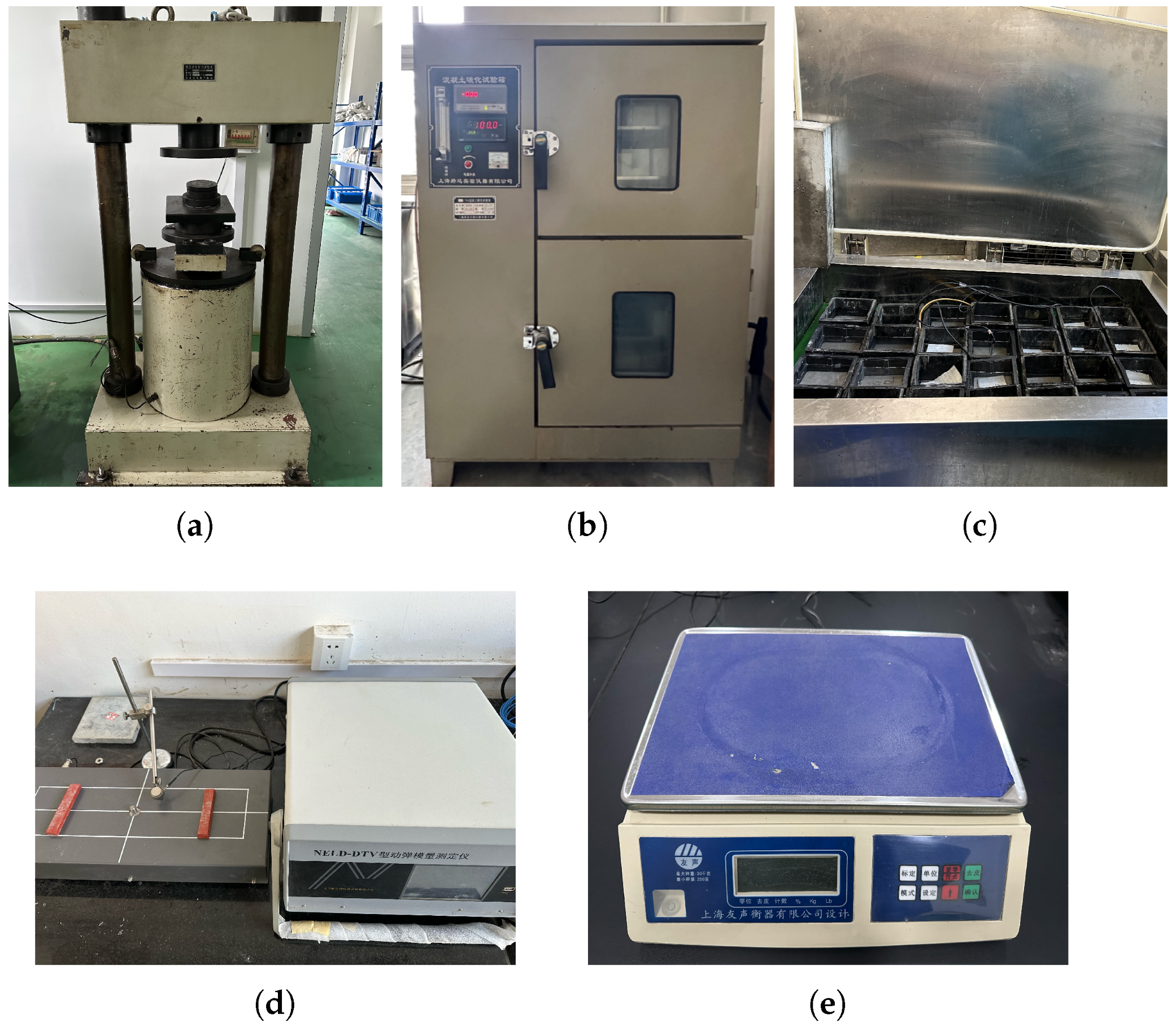
Figure 1. Experimental devices. (a) Digital display pressure tester, (b) concrete carbonation test chamber, (c) freeze–thaw test chamber, (d) dynamic elastic modulus tester, and (e) electronic scale.
Buildings 15 04179 g001
Figure 2. Appearance topography in different test conditions.
Buildings 15 04179 g002
Figure 3. Compressive strength in different test conditions.
Buildings 15 04179 g003
Figure 4. The M45-30-10 compressive strength in Na2SO4 solution of different concentrations.
Buildings 15 04179 g004
Figure 5. Weight loss in different test conditions.
Buildings 15 04179 g005
Figure 6. The M45-30-10 weight loss in Na2SO4 solution of different concentrations.
Buildings 15 04179 g006
Figure 7. RDME in different test conditions.
Buildings 15 04179 g007
Figure 8. The M45-30-10 RDME in Na2SO4 solution of different concentrations.
Buildings 15 04179 g008
Figure 9. Flowchart of the IOADE algorithm
Buildings 15 04179 g009
Figure 10. Results of the RDME in different conditions.
Buildings 15 04179 g010aBuildings 15 04179 g010b
Table 1. Cement quality indicators.
Cement VarietySetting TimeCompression Strength (MPa)Flexural Strength (MPa)Loss of Ignition (%)Specific Surface Area (m2/g)
Initial SettingFinal Setting3 d28 d3 d28 d
P.O42.590 min5.5 h21.542.14.07.12.5400
Table 2. Cement and fly ash chemical composition.
Chemical Composition (%) CaO SiO 2 Al 2 O 3 Fe 2 O 3 SO 3 MgO K 2 O Na 2 O
Cement61.3519.785.693.032.961.550.750.13
Fly ash6.3652.2021.877.980.432.341.592.67
Table 3. Composition of concrete specimens.
LabelWater to
Binder Ratio
Cement
(kg/m3)
Fly Ash
(kg/m3)
Sand
(kg/m3)
Stone
(kg/m3)
Water
(kg/m3)
Water-Reducing
Agent (kg/m3)
Fiber
(kg/m3)
Na2SO4
Solution (%)
M45-30-100.45420180563104727039.10, 3, 5, 10
M55-30-100.5534414760211172702.459.10, -, 5, -
M65-30-100.6529112562811172702.089.10, -, 5, -
M55-0-100.55491060211172702.459.10, -, 5, -
M55-15-100.554177460211172702.459.10, -, 5, -
M55-45-100.5527022160211172702.459.10, -, 5, -
M55-30-50.5534414760211172702.454.50, -, 5, -
M55-30-150.5534414760211172702.4513.650, -, 5, -
Table 4. Experimental scheme.
Test CodeTest ConditionsNotationsTest Procedures
1freeze–thawF(1) Water immersion for 4 days
(2) Freeze–thaw cycles 50 times
(3) Take steps 1–2 as a great cycle and repeat it
2freeze–thaw and carbonationFC(1) Water immersion for 4 days
(2) Freeze–thaw cycles 50 times
(3) Oven-dried at 60 °C for 2 days
(4) Accelerated carbonation for 3 days
(5) Take steps 1–4 as a great cycle and repeat it
3sulfate and freeze–thawSF(1) Na2SO4 solution immersion for 4 days
(2) Freeze–thaw cycles 50 times
(3) Take steps 1–2 as a great cycle and repeat it
4sulfate and freeze–thaw
and carbonation
SFC(1) Na2SO4 solution immersion for 4 days
(2) Freeze–thaw cycles 50 times
(3) Oven-dried at 60 °C for 2 days
(4) Accelerated carbonation for 3 days
(5) Take steps 1–4 as a great cycle and repeat it
Note: 1. Test code 1 and 2 are comparative tests. 2. All the tests are conducted for 5 great cycles.
Table 5. Results of the model parameters.
abcdefghlmk
W n SF6.1685−9.77892.5295−0.3734−4.43937.7054−3.0650−0.19723.48160.2098−0.4236
SFC3.68013.16881.67510.23333.86344.7329−4.0047−0.00415.94903.5623−0.8284
E n SF−6.47141.62792.82070.1644−0.5890−1.22220.56050.6774−0.8560−0.00310.4967
SFC−2.14057.9662−5.24060.4985−0.94210.3707−0.19661.7825−1.7366−0.00630.3848
Table 6. Results of the evaluation indexes for the SF condition.
GmIndexes W n E n
DEADEIOADEDEADEIOADE
500 R 2 0.72430.79360.81950.88940.93240.9531
MAE0.39890.32610.29850.03050.02460.0273
RMSE0.32280.29830.27480.04020.03490.0316
2000 R 2 0.88540.93680.95300.90170.95840.9755
MAE0.30170.26340.24810.02970.02310.0196
RMSE0.28930.26950.25440.03420.02880.0219
5000 R 2 0.90580.95620.97140.95340.97950.9864
MAE0.24750.23880.22640.02080.01790.0165
RMSE0.25030.24690.23710.02650.02040.0187
Table 7. Results of the evaluation indexes for the SFC condition.
GmIndexes W n E n
DEADEIOADEDEADEIOADE
500 R 2 0.89940.91360.95150.90170.92560.9503
MAE0.38490.32540.29260.05760.38430.0307
RMSE0.34610.30270.28940.04770.03950.0299
2000 R 2 0.92430.95070.96150.93150.94360.9717
MAE0.31240.29180.27690.04230.03180.0251
RMSE0.30040.28970.27220.03250.03090.0272
5000 R 2 0.95060.97950.98140.96140.97760.9869
MAE0.29370.24610.23680.03610.02930.0226
RMSE0.29830.26290.25170.02930.02580.0214
Disclaimer/Publisher’s Note: The statements, opinions and data contained in all publications are solely those of the individual author(s) and contributor(s) and not of MDPI and/or the editor(s). MDPI and/or the editor(s) disclaim responsibility for any injury to people or property resulting from any ideas, methods, instructions or products referred to in the content.