Article

The Deformation Characteristics and Patterns of Adjacent Existing Metro Structures Caused by Foundation Pit Excavation Under Different Support Forms

1
Gansu Construction Investment (Holdings) Group Co., Ltd., Lanzhou 730050, China
2
School of Civil and Hydraulic Engineering, Lanzhou University of Technology, Lanzhou 730050, China
3
School of Civil Engineering, Shandong University, Jinan 250061, China
4
Gansu Academy of Building Research (Group) Co., Ltd., Lanzhou 730070, China
*
Authors to whom correspondence should be addressed.
Buildings 2025, 15(22), 4178; https://doi.org/10.3390/buildings15224178
Submission received: 1 November 2025 / Revised: 15 November 2025 / Accepted: 17 November 2025 / Published: 19 November 2025
(This article belongs to the Section Architectural Design, Urban Science, and Real Estate)

Abstract

With the continuous development of cities, underground space has become increasingly crowded, making the efficient and safe utilization of underground space an urgent issue to address. At present, research on foundation pit construction adjacent to existing subway structures mainly focuses on the impact of pit excavation on tunnels. While these studies have established a basic understanding of how pit excavation affects tunnels, research on adjacent subway stations and tunnels is nearly nonexistent—especially regarding the impact of the coupling effect between stations and tunnels during the excavation process. Additionally, most studies are conducted in soft soil areas, with no research yet on the impact in loess areas. To study the impact of foundation pit construction on subway tunnels and stations and reveal their coupling mechanism, model tests and numerical simulations were conducted based on actual engineering conditions. The model box had dimensions of 1.5 m in length, 1 m in width, and 1.2 m in height, while numerical simulations adopted the same dimensions as the actual project. Two different support structures—pile-anchor support and double-row pile support—were used for separate research and comparative analysis. The results show that with the increase in excavation depth, the foundation pit unloading effect becomes increasingly obvious. The pressure borne by both support structures increases, and the disturbance to the subway structure also becomes more significant. The maximum disturbance of tunnel earth pressure under the double-row pile support is 7.92 kPa, which is 224% higher than that under the pile-anchor support. The impacts on the subway tunnel and station under the double-row pile support are significantly greater than those under the pile-anchor support. Additionally, affected by the station, the locations of maximum tunnel deformation are not at the positions corresponding to the center of the foundation pit, but offset 10 m away from the station. Both the station and the tunnel exhibit a certain degree of uplift deformation, and the tunnel has significant convergence deformation in the horizontal direction. The maximum disturbance of the bending moment under the double-row pile support is 101.87 N·m, which is 19.8% higher than that under the pile-anchor support. This study reveals the coupling mechanism of the impact of adjacent foundation pit excavation on subway structures (including subway stations and tunnels) and presents the corresponding causes and phenomena, and it is of great significance for the development of related projects in loess areas and the protection of subway structures.

1. Introduction

With the rapid advancement of urbanization, the scale of underground space development continues to expand, and deep excavation projects are becoming increasingly common in urban core areas. However, many excavation projects are located near existing metro structures due to site constraints—these metro lines, as the “lifelines” of urban transportation, have high daily passenger flows and strict operational precision requirements. They are highly sensitive to surrounding soil deformation and structural disturbances. During excavation, the original soil stress balance is disrupted, leading to displacement, settlement, and stress redistribution in the surrounding strata. If the deformation exceeds the safety limits of the metro structures, it may cause track irregularities, structural cracks, or even operational interruptions, directly threatening public safety. The study of excavation near existing metro structures is of great importance. Excessive deformation can cause separation, misalignment, and track warping, affecting the operation of the metro trains. In severe cases, excessive deformation between tunnel segments may lead to water and sand leakage, causing major deformations and damage to the tunnel, compromising metro operation safety [1,2]. The safety and stability of metro structures are the foundation for the normal operation of urban transportation. As typical “close-proximity construction” scenarios, excavation works directly influence the disturbance control of adjacent metro structures, which is crucial for ensuring the safety of millions of passengers and the efficient use of underground space resources. In recent years, multiple incidents of metro structural deformation caused by excavation projects have highlighted the high-risk nature of such projects, necessitating systematic research to clarify the disturbance patterns. Numerous scholars, both domestic and international, have conducted relevant studies on the impact of excavation on existing metro structures. Methods include numerical simulation analyses combined with engineering practices [3,4,5,6,7,8,9,10], theoretical analyses [11,12,13], and model tests [14,15,16,17].
Most scholars’ research focuses on soft soil areas. Kim et al. [18] found in two-dimensional model tests that, when excavating near newly constructed tunnels in soft soil conditions, vertical arching effects above the tunnel crown caused a significant increase in soil pressure on the side of the existing tunnel near the new tunnel. Xu Sifang et al. [19] conducted deformation monitoring of adjacent operational tunnels during excavation, analyzing the tunnel deformation from the beginning to the end of the excavation process. They found that the maximum deformation occurred between the construction of the enclosure structure and the excavation phase. Zhang Xu et al. [20] suggested that during excavation, it is essential to monitor both the tunnels and support structures to ensure the safety of excavation. Guan Lingxiao et al. [21] applied the Loganathan formula to calculate vertical and horizontal displacements at the tunnel axis position caused by excavation, incorporating the angle between the tunnel and pipeline in the deformation analytical formula. Lo [22] studied a foundation pit project located above an existing tunnel in the clay area of Toronto, using finite element numerical analysis to predict the additional displacement of the tunnel, pointing out that numerical simulation methods can effectively predict and assess additional displacement of metro tunnels to a certain extent. Yu Jiaxin et al. [23] obtained deformation data through on-site monitoring of soft soil foundation pits and analyzed it, concluding that tunnel deformation is predominated by settlement. They noted that the current influence zoning is relatively conservative, and suggested expanding it to four times the excavation depth outside the foundation pit to ensure subway operation safety. Zhang Zhiguo et al. [24] established a mechanical model for the deformation of adjacent existing small-curvature-radius tunnels induced by soft soil foundation pit excavation based on fractional-order Merchant viscoelasticity. By means of the finite difference method and forward/inverse Laplace transforms, they derived the time-domain solutions for the radial and vertical deformations of the existing small-curvature-radius tunnels.
Currently, most scholars focus their analysis solely on tunnels, and their studies are based on symmetric conditions, failing to consider the impact of the presence of stations on tunnels. Klar et al. [25] derived the settlement curve distribution of pipelines under concentrated load using the Winkler foundation beam model. They then derived the maximum bending moment expression for an infinitely long beam under additional load and compared it with numerical results, finding good agreement between the two. Attewell et al. [26] studied the effects of tunnel excavation on adjacent underground pipelines and surrounding buildings. Their analysis indicated that, under identical loading conditions, the displacement and bending moment values from the Winkler foundation beam model and the elastic homogeneous half-space foundation beam model were the same. T. E. Vorster [27] et al. proposed a method for estimating the maximum bending moment of continuous pipelines affected by tunnel-induced ground movements, and evaluated the effectiveness of this method as an upper bound approximation using centrifuge testing. Huang Zhenke [28], aiming to explore the feasibility and effectiveness of construction protection measures for foundation pits adjacent to underlying tunnels and reveal the law of tunnel deformation caused by the excavation of overlying foundation pits, proposed that effective control of deformation and stability could be achieved by adopting full-process measures for adjacent construction in terms of “time” and “space”. Jia Rui et al. [29] studied the impact of foundation pit excavation on adjacent tunnels under different degrees of prior tunnel construction disturbance by employing the S-CLAY1S constitutive model for structured soft clay. Through numerical simulations, they analyzed the stress state and structural changes in the surrounding soil under different degrees of tunnel construction disturbance. The results showed that the greater the degree of tunnel construction disturbance, the greater the stress ratio of the soil around the tunnel, as well as the degree and scope of structural damage. Chen Renpeng et al. [30], focusing on the law of lateral force behavior and deformation of shield tunnel structures adjacent to foundation pit excavation, proposed a theoretical calculation method for the lateral force of shield tunnels that considers the influence of retaining structure deformation. They verified the reliability of the theoretical calculation method for radial additional loads on tunnels through the 3D finite element calculation results of a practical project and the results of centrifugal model tests on foundation pit excavation adjacent to tunnels in dry sand strata. Huang Minghua et al. [31] introduced a discontinuous foundation beam model considering the influence of inter-ring joint rotation and dislocation displacement to analyze the deformation of underlying shield tunnels induced by foundation pit excavation, and obtained the relationship between joint stiffness, tunnel displacement, and dislocation amount. Feng Guohui et al. [32] simplified the tunnel into a Timoshenko beam that can consider both longitudinal stiffness and shear deformation, adopted the three-parameter Kerr foundation model for the foundation, and obtained the analytical solution for the longitudinal deformation of the tunnel using the finite difference method while considering the boundary conditions at both ends of the tunnel. Wei Gang et al. [33] studied the horizontal displacement law of existing tunnels outside isolation piles under the influence of foundation pit excavation, established a three-dimensional mechanical calculation model of foundation pit, isolation piles, and existing tunnels, considered the stratum loss caused by foundation pit excavation, derived the calculation formula for additional stress induced by foundation pit unloading, and established the flexural deformation influence zone of isolation piles based on the Kerr foundation model. Zhang Zhiwei et al. [34] analyzed the deformation characteristics of shield tunnels during the overcrossing construction of new tunnels using a discontinuous foundation beam model, considering the influence of inter-ring joints. Xu Sifa et al. [35] calculated the earth pressure on the pit wall due to foundation pit excavation and unloading according to the non-limit earth pressure calculation method, obtained the additional load on the adjacent tunnel during the foundation pit excavation stage using the Mindlin solution formula, regarded the tunnel structure as an Euler beam on a Winkler foundation beam, established the differential equation of the elastic foundation beam, and proposed an analytical method for the horizontal displacement deformation of the tunnel. Ying Hongwei et al. [36] presented the vertical additional load at the adjacent tunnel caused by foundation pit excavation based on the Mindlin solution; introduced a modified subgrade reaction coefficient that can consider the effect of arbitrary tunnel burial depth, simplified the existing tunnel into an Euler-Bernoulli beam placed on a Pasternak foundation, and further proposed a simplified calculation method for the response of adjacent existing tunnels under foundation pit excavation. Zhou Zelin et al. [37] regarded the tunnel as an elastic underground continuous beam to analyze the force and deformation of the tunnel itself, derived the finite element coupling equilibrium equation for the interaction between the tunnel and the surrounding soil, introduced an elastic half-space layered model to analyze the influence of foundation pit unloading on the deformation performance of soil and tunnels, and established a coupling analysis method for the influence of foundation pit excavation on adjacent tunnels in layered foundations. Guan Lingxiao et al. [38] proposed an analytical calculation method for the deformation of adjacent pipelines caused by single-well dewatering based on the large well method theory, and derived the calculation formula for effective stress induced by dewatering. Liang Rongzhu et al. [39] constructed the finite difference equation of the longitudinal beam-spring model on an elastic foundation to solve the problem of discontinuous deformation of inter-ring joints and pipe rings, derived the longitudinal deformation formula of existing shield tunnels under external loads, and established the longitudinal deformation solution of existing shield tunnels caused by the overcrossing and undercrossing of new tunnels.
Existing research has not yet fully clarified the coupling mechanism of “foundation pit excavation-stratum response-subway structure deformation” in complex environments. In engineering practice, designs often rely on experience, which tends to result in over-support or insufficient support—problems that both increase costs and create potential safety hazards. Based on an actual project, this study employs scaled model tests and numerical simulations to investigate the deformation law of existing subway structures adjacent to excavated foundation pits. It reveals the deformation patterns and coupling mechanism of subway stations and tunnels, analyzes the subway deformation law under different support types, further uncovers the mechanical responses of both support structures and subway structures, and examines the influencing factors and their causes. Additionally, the study explores the impact of foundation pit excavation on adjacent subway stations and tunnels under different support types in loess areas, providing a certain reference value for related projects in such areas.

2. Engineering Situation

This project is located in Gansu, where the surrounding environment is complex: the metro station is 16.2 m to the east, residential neighborhoods to the north and west, and a commercial street is to the south. The relationship between the foundation pit and the existing metro station is shown in Figure 1. The foundation pit is fan-shaped, with an excavation area of approximately 50,188 m2 and an excavation depth of 16 m. According to the geological survey report, the strata within the excavation range consist of mixed fill and three layers of gravel, with the gravel layers increasing in density from top to bottom. Considering the actual conditions of the project and common types of support structures, due to the proximity to subway stations and tunnels, and combined with the foundation pit excavation depth, the foundation pit excavation is classified as Grade I. Therefore, a robust support structure is required. The pile-anchor support structure, as a universally recognized structure with excellent support performance, is selected as one of the types for this test. The double-row pile support structure is also selected as one of the types because its smaller construction spacing can meet the specification requirements for subway protection. The objective is to compare and analyze the impact of different support structures on the adjacent metro station tunnel during deep foundation pit excavation.

3. Test Design

3.1. Similar Design

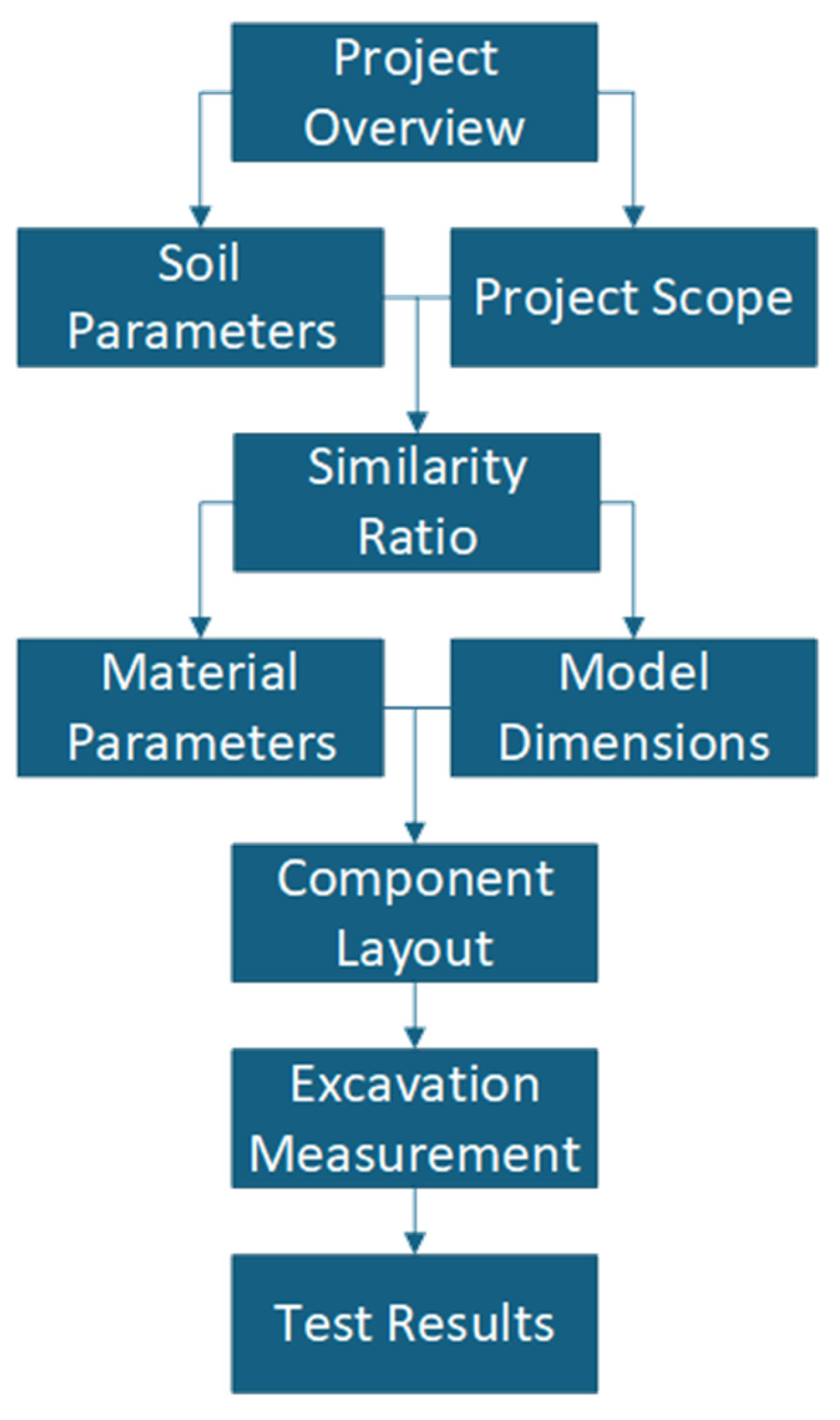
Model tests can effectively reflect the characteristics of engineering construction and the laws of structural changes. These tests are mainly divided into two categories: regular gravity model tests (including full-scale model tests and scaled model tests) and centrifuge model tests. Among them, centrifuge model tests require the use of a centrifuge to simulate the gravitational effect by compensating for the gravitational similarity through centrifugal acceleration, thus achieving the required N × g (N times the gravitational acceleration). However, centrifuge tests face high maintenance costs, large energy consumption, and technical limitations, making it difficult to achieve ideal results with larger models. Full-scale model tests, although providing high data measurement accuracy and strong realism, can directly reflect the physical laws of the prototype without the need for similarity conversion. However, they involve significant land and material costs, with test periods lasting months or even years. Destructive tests also carry substantial safety risks and lack repeatability. A scaled model test involves scaling down the prototype into a smaller model for experimentation in accordance with similarity criteria. Although it has the limitation of stress field loss, its advantages of low cost and short cycle are obviously superior to those of centrifuge model tests and full-scale model tests, but the selection and preparation of similar materials are crucial for accurately reflecting the true physical laws. Therefore, using scaled model tests as a research method is relatively easier to implement. Based on this, considering the practical dimensional feasibility of the anchor cable, similar material, the manufacturing dimensions of the model box, and the rationality of similarity to practical engineering, the geometric similarity coefficient is preliminarily set as Cl = 50. That is to say, the ratio of the model to the actual project in length is 1/50, and all subsequent similarity relationships refer to the ratio of the model to the actual project. The similarity coefficients for the model’s gravitational acceleration and density are set as Cg = Cρ = 1. The similarity relationship for the model is determined using similarity theory and dimensional analysis, as shown in Table 1. The overall experimental design steps are shown in Figure 2.
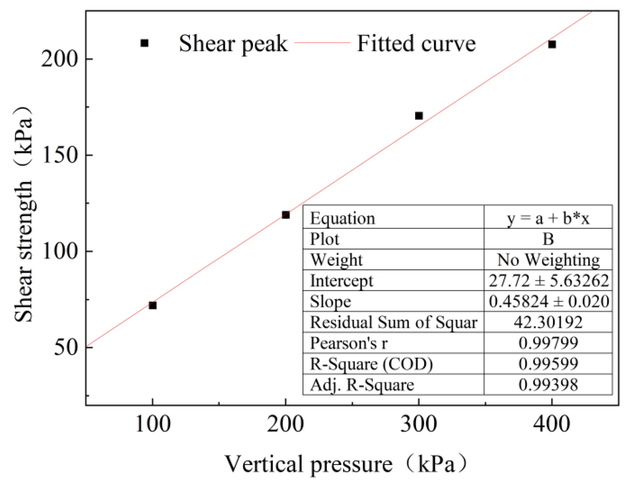
Due to the natural aridity of Gansu and its relatively thick loess layers, most of the local soil mass is in an unsaturated state. Considering the actual design of the test, the loess from Gansu was thus selected as the prototype material, with the natural dry density of 1.66 g/cm3 was used as the test soil density, and the natural moisture content of 14% adopted as the fixed moisture content. In the experiment, the loess with a moisture content of 14% was placed layer by layer into the model box, ensuring its dry density matched the natural dry density. After compaction, samples were taken from the formed model using a ring knife, and the physical and mechanical parameters of the loess were measured through direct shear tests. The fitted curve is shown in Figure 3. The cohesion (c) was found to be 27.73 kPa, and the internal friction angle (φ) was 24.62°. To reduce the cohesion to 1/50 [40] of its original value, the experiment used sand that was washed and sieved through a 2 mm sieve, mixed with the loess. By adjusting the sand-to-loess ratio, the material properties were modified. The final mixture, consisting of 15% loess and 85% sand, was determined to be the optimal formulation for the experiment. The arid and rainfall-deficient Northwest China features loess basically in an arid state. The test materials are based on natural loess in Northwest China, meeting the similarity ratio of physico-mechanical properties and applying to arid loess areas in Northwest China.

3.2. Selection of Similar Materials

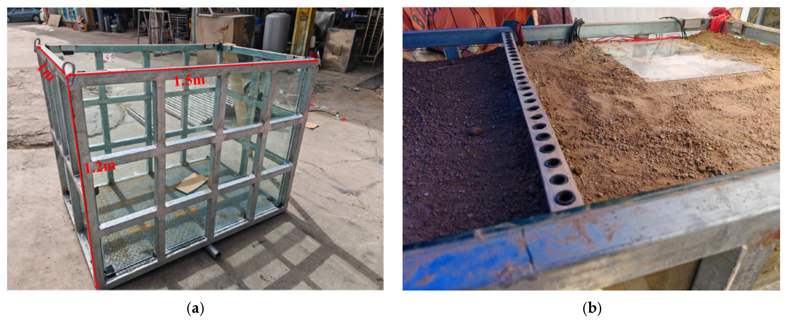
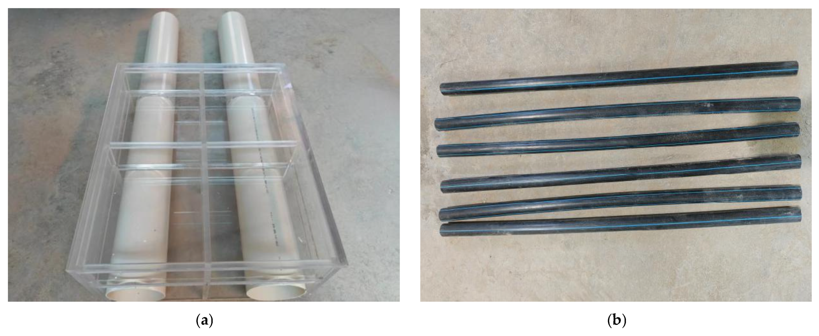
In this experiment, a model box with dimensions of 1.5 m (length) × 1 m (width) × 1.2 m (height) was used. One short side of the model box was blocked with a half piece of 10 mm thick tempered glass, while the other side walls are made from whole pieces of 10 mm thick tempered glass, as shown in Figure 4. The side wall was set as a friction-reduced boundary, the top as a free boundary, and the bottom as a fixed boundary to ensure consistency with the working conditions in actual engineering. The prototype of the tunnel is a tubular structure with a thickness of 0.5 m and an outer diameter of 6.7 m. The prototype of the pile is a cylindrical structure with a diameter of 1 m and a length of 26 m, with a total of 33 piles. The anchor cables are 3S15.2 steel strands, each with a length of 13 m. Based on the bending stiffness equivalence principle and Equations (1) and (2), PVC pipes with an outer diameter of 125 mm and wall thickness of 2.6 mm are selected as the tunnel simulation material, and PE pipes with an outer diameter of 20 mm and wall thickness of 2.3 mm are chosen as the pile simulation material, as shown in Figure 5a. Similarly, 1 cm thick acrylic plates are selected as the simulation material for the station’s roof and side walls. According to the geometric similarity ratio, the pile length is 52 cm, the tunnel width is the same as the model box’s width (1 m), and the overall dimensions of the station are 50 cm × 42 cm × 24 cm, as shown in Figure 5b. Based on the compression stiffness equivalence principle and Equation (3), iron wire with a diameter of 0.5 mm is used as the simulation material for the anchor cables, with a length of 26 cm. The specific material parameters are shown in Table 2.
d m = d p 1 μ m 2 1 μ p 2 ρ m ρ p E p n 5 E m 1 3
D m = D p n = 6300 50 = 126 m m
E A p = π = E A m

3.3. Model Structure Design

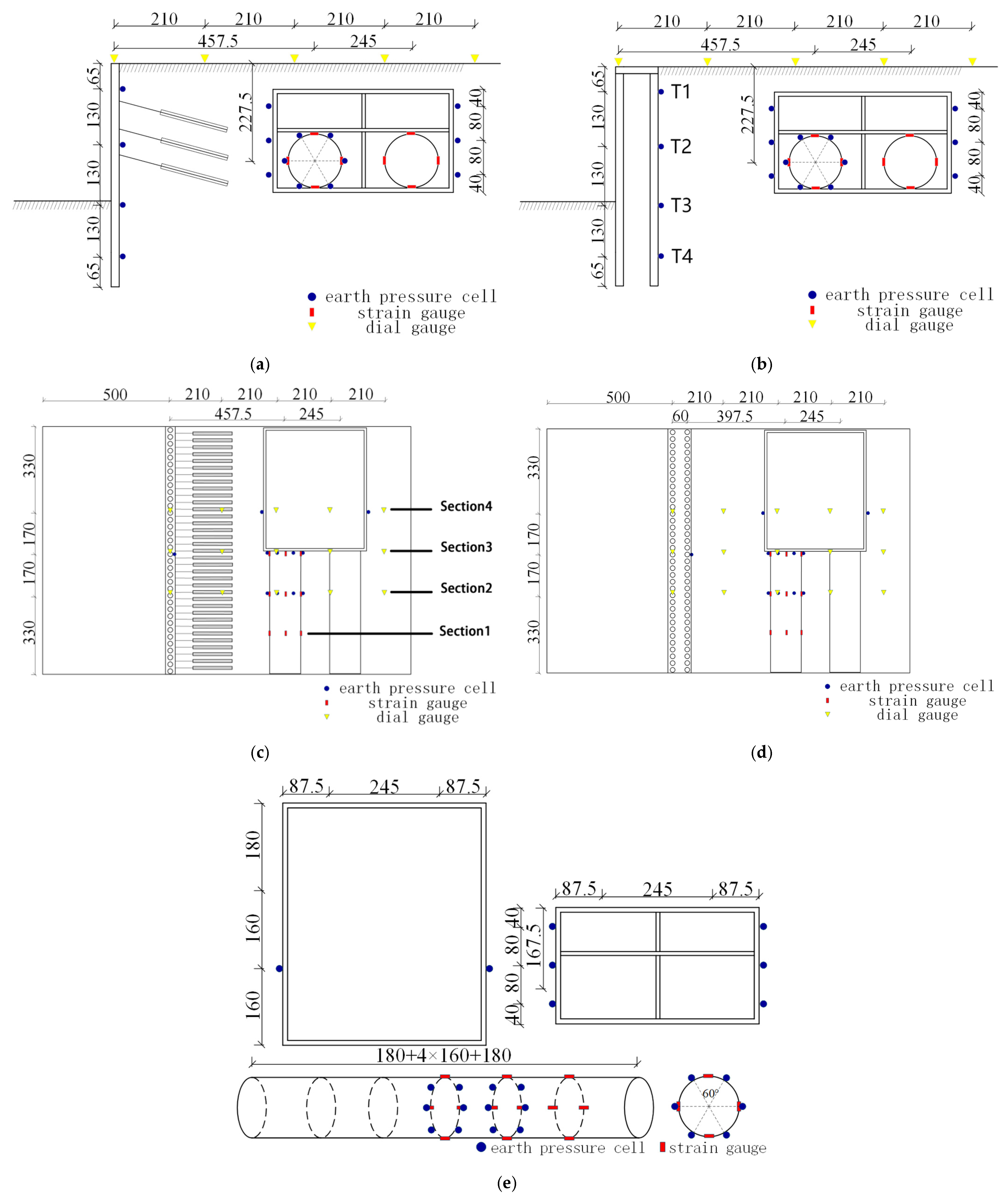
This experiment compared two types of support structures for analysis. The measurement system primarily included earth pressure cells, strain gauges, dial indicators, and the DH3816N (Manufactured by Donghua Testing Co., Ltd., Taizhou City, China) static strain testing instrument. In the study, the earth pressure cells used are YTDZ-type (Manufactured by Yituo Sensing Technology Co., Ltd., Changsha, China) resistive strain full-bridge earth pressure cells with a measurement range of 0.2 MPa, and the strain gauges are of model BMB 120-3AA (Manufactured by Chengdu Electrical Measurement & Sensing Technology Co., Ltd., Chengdu, China). The earth pressure cells were calibrated using the calibration coefficients provided by the manufacturer, while the strain gauges were connected to the testing instrument to perform temperature compensation. The layout positions of the earth pressure cells, strain gauges, and dial indicators are shown in Figure 6. The strain gauges were attached longitudinally along each structure, with the section farthest from the station was designated as Section 1. Moving towards the station, the sections were sequentially named Section 2, Section 3, and Section 4. The detailed location is shown in Figure 6c.

3.4. Test Conditions and Steps

3.4.1. Filling Soil and Placing Components

Before the start of the test, lubricating oil was first applied to the side walls of the model box to reduce the impact caused by the boundary effect. The density was controlled using the volume method, with the quantified soil uniformly poured into the model box and compacted to the required height. The first 60 cm is filled in layers of 10 cm, with each layer compacted before the next layer is added. When the filling reaches 68 cm, the pile body is embedded. The cap beam was first nested onto the pile to fix its position, followed by the filling of 4 cm, 10 cm, and 10 cm soil layers in sequence. Next, the simulated station structure and tunnel were placed, and the third layer of waist beams and anchors (not yet locked) are positioned as shown in Figure 6a. Two more layers of 6 cm soil are then added, while simultaneously placing the second and first layers of waist beams and anchors in the same manner. Finally, the soil is filled to the top of the model box. During the filling process, no excessive compaction is allowed for each layer to avoid affecting the sensor readings. After compaction, the density is verified using the ring knife method. Samples are taken from four directions for four direct shear tests to determine the shear strength parameters of the soil. Additionally, three soil samples are collected to measure physical properties, ensuring that the density and void ratio of each soil layer meet the required specifications based on the material property tests.

3.4.2. Excavation Process

The total excavation depth was 32 cm, carried out in 6 stages. The excavation depths for each stage was 5 cm, 5 cm, 6 cm, 6 cm, 5 cm, and 5 cm, respectively. Excavation was carried out using an iron scoop, and it must be performed slowly to avoid disturbing the metro structure, which could affect the accuracy of the test results. The specific procedure is as follows: Excavation to a depth of 5 cm is completed, followed by a 5 min rest period before the first data collection; excavation to a depth of 10 cm is completed, followed by a 5 min rest period before the second data collection; excavation to a depth of 16 cm is completed, followed by a 5 min rest period before the third data collection. Afterward, a dynamometer is used to apply a fixed tension, and the first layer of anchors were tensioned and locked by tightening the nuts to tension and lock the first layer of anchors. For the subsequent excavations (Stages 4 and 5), the second and third layers of anchors were tensioned and locked, respectively, after each excavation. The remaining steps follow the same procedure as described above. The detailed process is shown in Table 3. To avoid data changes and unclear trends caused by the initial stress field, the test measurement system was preprocessed to set the initial stress to 0.

3.4.3. Test Working Condition Setting

The experiment primarily analyzed the impact of foundation pit excavation on the adjacent existing metro tunnels and stations under different support structures. Therefore, two sets of working conditions were established, as shown in Table 4. Apart from the support structures, the rest of the experimental setup was identical.

4. Result Analysis

4.1. Earth Pressure Around the Tunnel

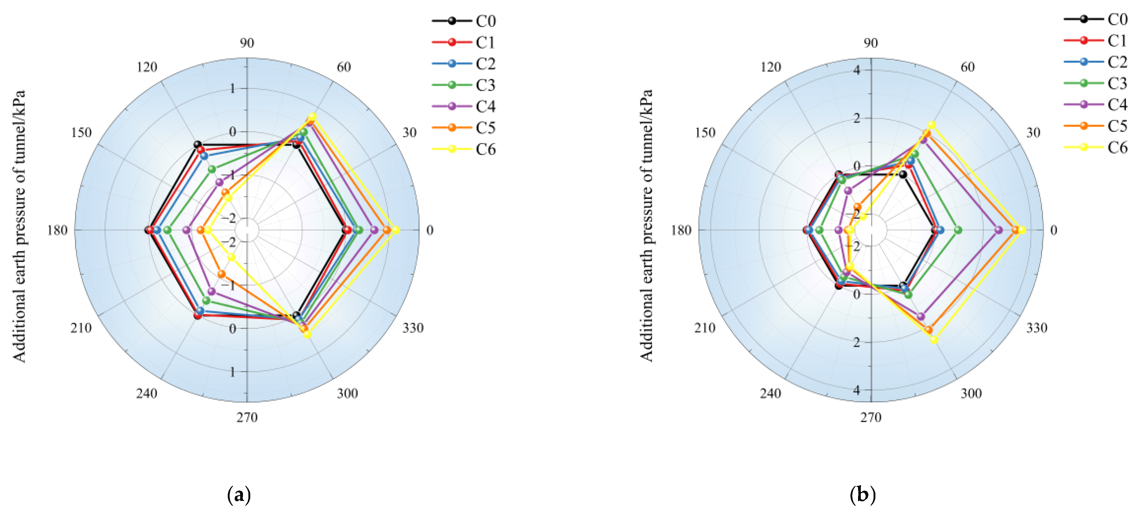
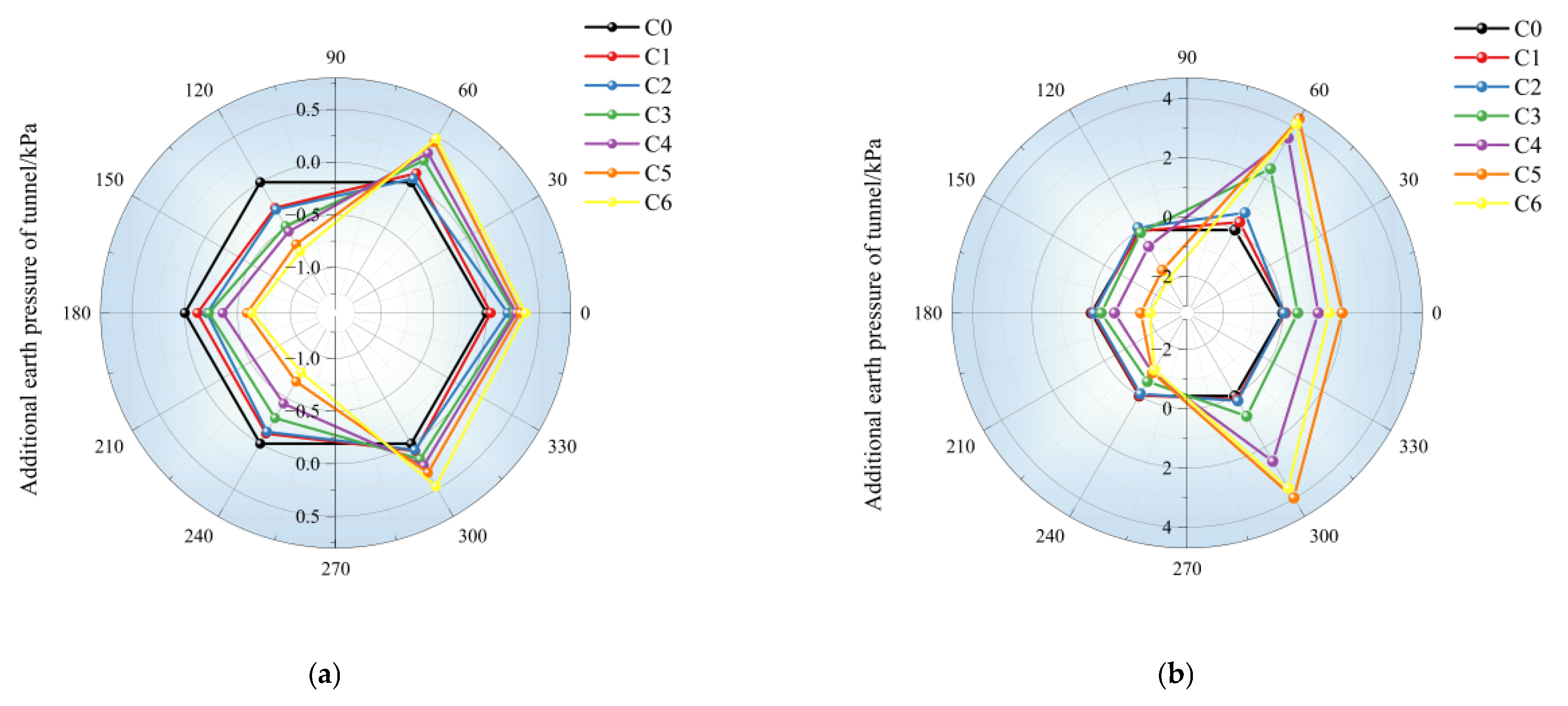
Figure 7 and Figure 8 illustrated the impact of foundation pit excavation on the soil pressure of adjacent existing metro tunnels under different support structures. Figure 7a,b showed the soil pressure variation for Section 3 under pile-anchor support and double-row pile support, respectively, while Figure 8a,b corresponded to Section 2. In these figures, the left side (180° position) was the excavation side, with six working conditions in total (C0 represents the initial state). To analyze the impact of excavation on soil pressure, the soil pressure of the initial state (C0) was set to zero to present the changes more clearly. The excavation stages were named C1 through C6; see Table 3 for details. From the data, it could be seen that, for both Section 2 and Section 3, the soil pressure variation under double-row pile support was significantly greater than that under pile-anchor support. In both sections, under both support structures, the soil pressure on the left side decreased while that on the right side increased, indicating that the soil pressure on the excavation side decreased significantly, while that on the corresponding opposite side increased. Specifically, compared to pile-anchor support, double-row pile support resulted in an increase of 1.19 kPa at the right arch waist and a decrease of 1.34 kPa at the left arch waist in Section 2, and an increase of 2.46 kPa at the right arch waist and a decrease of 0.44 kPa at the left arch waist in Section 3. This was because foundation pit excavation unloading reduced the earth pressure on the excavation side, which led to stress redistribution in the surrounding soil. According to the Mohr-Coulomb criterion, the shear strength of soil had a linear correlation with normal stress; thus, a decrease in normal stress would lower the soil’s shear strength. Consequently, uneven earth pressure would cause the tunnel to displace and deform toward the excavation side until the earth pressure reached equilibrium. Additionally, under both support structures, the soil pressure at the tunnel (60°) and (300°) increased, with a more significant increase under double-row pile support. In Section 2, the pressure at these positions increased by 3.65 kPa and 3.12 kPa, respectively, while in Section 3, the pressure increased by 1.64 kPa and 1.1 kPa. The maximum rate of increase could reach up to 700%, with the increases being more pronounced in the vertical direction. This led to a “horizontal egg-shaped” deformation of the tunnel, with more severe deformation occurring under double-row pile support.

4.2. Earth Pressure on the Side Wall of the Station and Pile-Soil Pressure

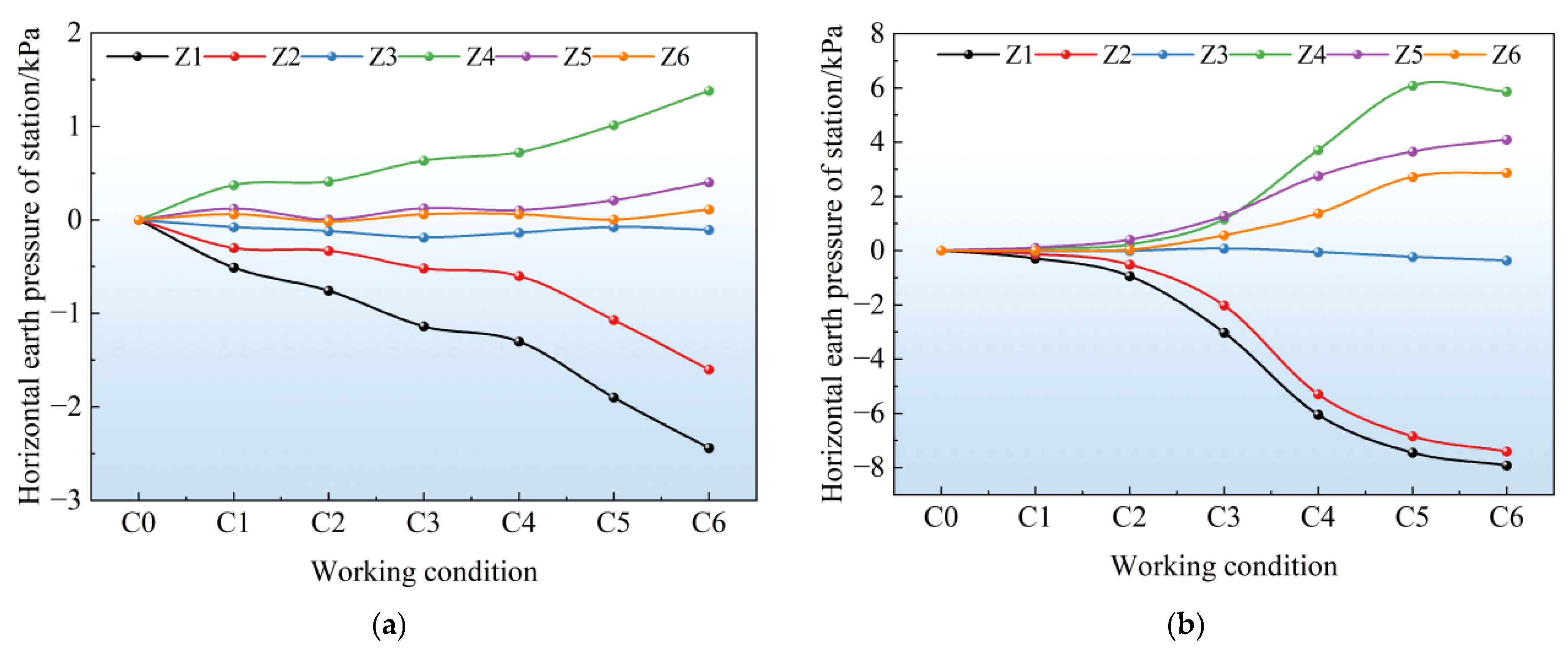
Figure 9 presented a comparative analysis, which indicated that the soil pressure variation on the station under the pile-anchor support structure was more gradual, and the amplitude was significantly smaller than that under the double-row pile support structure. During double-row pile support, the soil pressure variation on the station was mainly concentrated between excavation working conditions 3 and 5, which corresponded to the buried depth of the station. This suggested that excavation to the depth of the underground structure caused the most disturbance. Among them, Z1 to Z3 represented the soil pressure gauges on the left side of the station, arranged from top to bottom, and Z4 to Z6 were the corresponding gauges on the right side. From the figure, it was evident that under both support structures, the soil pressure on the left side of the station decreased, while it increased on the right side. The variation amplitude was larger for Z1, Z2, Z5, and Z6, indicating that excavation unloading of the foundation pit had a more significant impact on the station, causing the station to tilt toward the excavation side of the pit. Specifically, under the pile-anchor support structure, the maximum decrease in soil pressure was 2.44 kPa and the maximum increase was 1.38 kPa. In the case of the double-row pile support structure, these values were 7.92 kPa and 5.86 kPa. Compared with pile-anchor support, the maximum decrease in soil pressure under double-row pile support was 224% greater; obviously, pile-anchor support caused less disturbance to the station.
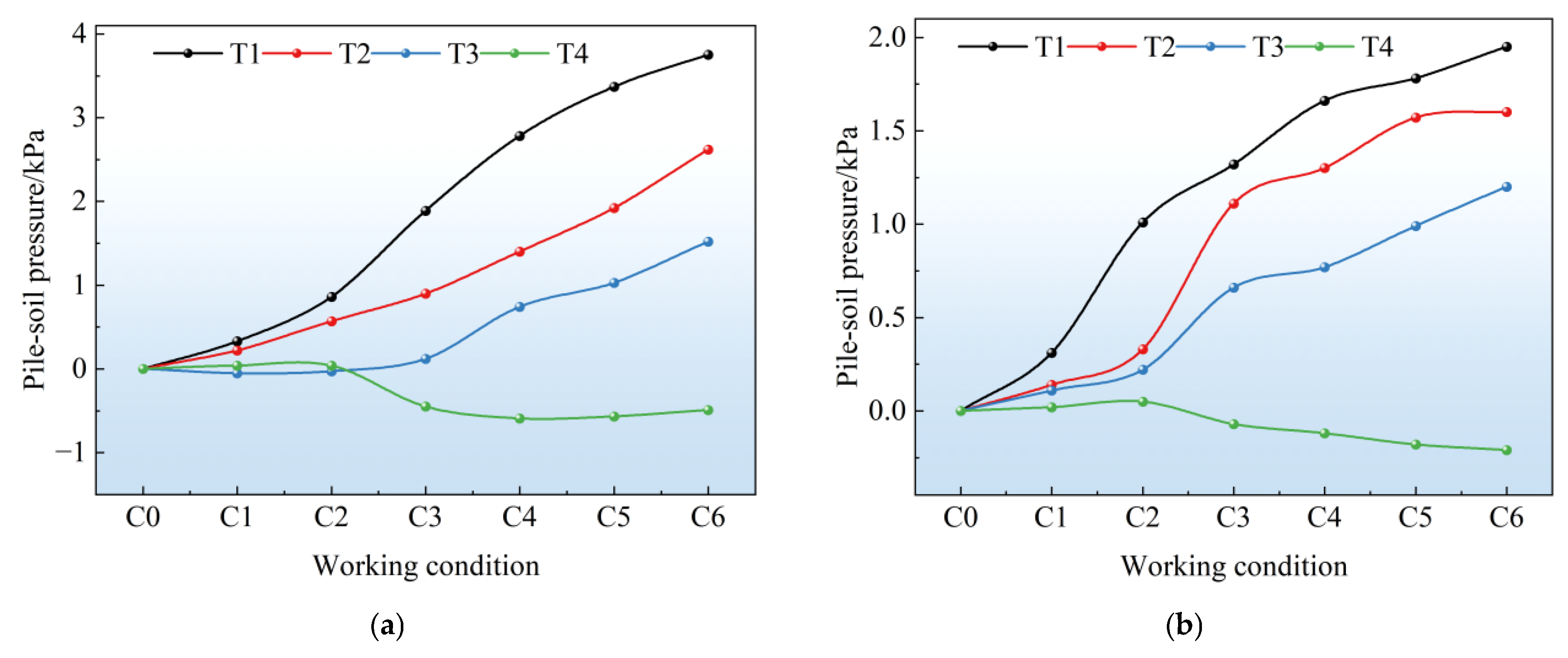
Analysis of Figure 10 showed that the pile-anchor support structure bore greater earth pressure than the double-row pile support structure, with the maximum increment of earth pressure on the pile body reaching 3.75 kPa for the former and 1.95 kPa for the latter. The layout positions of T1~T4 are shown in Figure 6b. During construction, controlling soil deformation was the core of protecting existing underground structures, as the damage to adjacent existing metro structures mainly stemmed from soil displacement. Moreover, when the support structure bore greater earth pressure within a reasonable range, it could effectively reduce soil relaxation caused by soil displacement, mitigate stratum loss and the transmission of settlement, and thus better protect adjacent existing metro structures. Due to the presence of anchor cables, the pile-anchor support could better anchor the soil mass. According to the Mohr-Coulomb criterion, the earth pressure borne by the pile-anchor support structure exerted a reaction force on the soil. As a result, the normal stress of the soil under the pile-anchor support structure should have been greater than that under the double-row pile support structure. Therefore, the soil deformation under the pile-anchor support structure should have been smaller. In conclusion, the pile-anchor support structure had a better effect on controlling the deformation of surrounding soil than the double-row pile support structure, which was consistent with the previously mentioned conclusion that it caused less disturbance to adjacent existing metro structures.

4.3. Longitudinal Bending Moment of the Tunnel

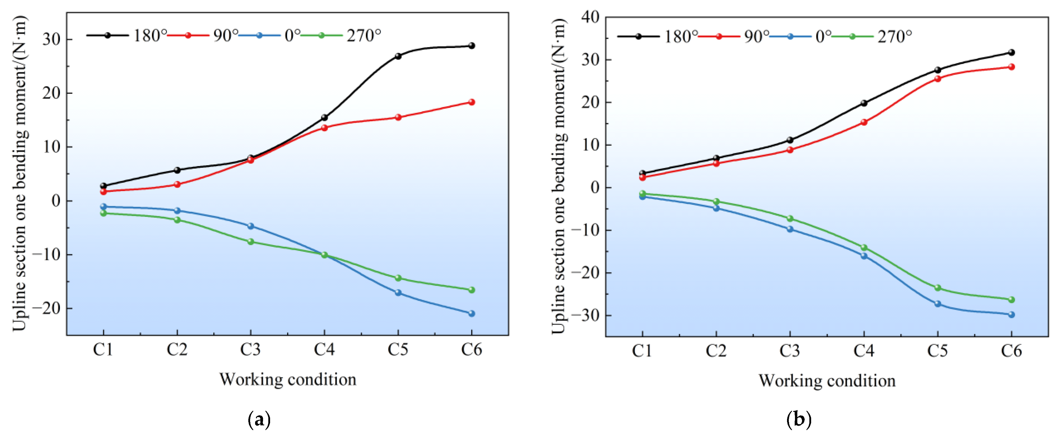
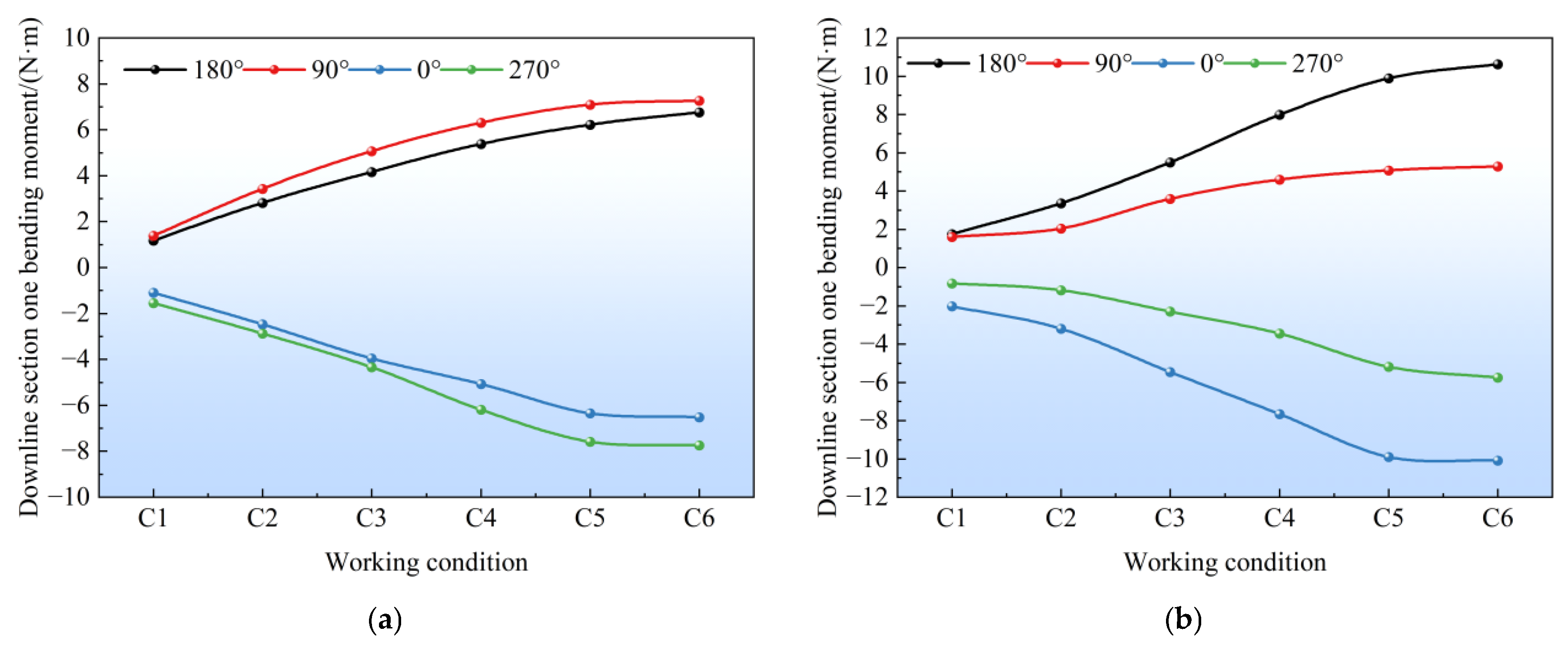
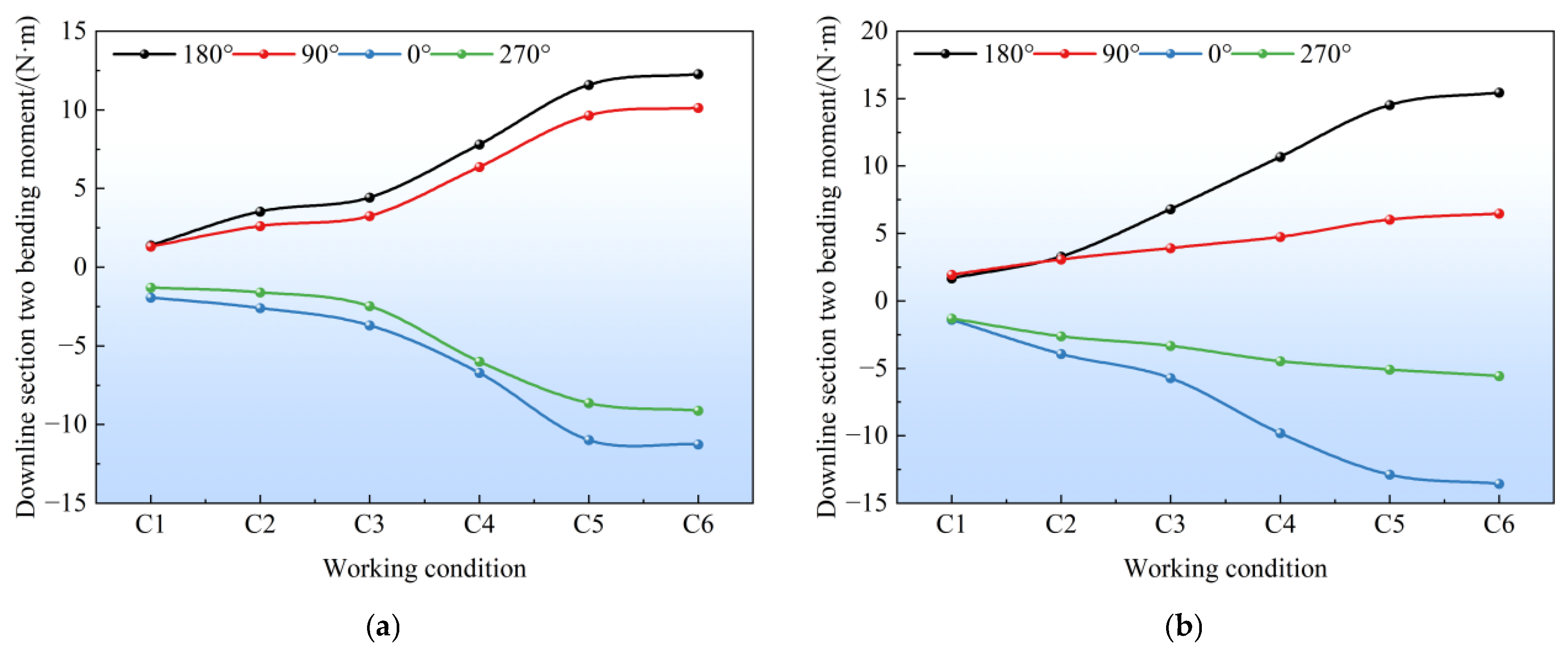
In this experiment, the strain gauges were adhered along the longitudinal direction, and the measured strains and moments represented the longitudinal deformation of the metro tunnel and station. Figure 11 and Figure 12 show the moment measurements of the tunnel on both the left and right sides (with the left side being the up-line and the right side being the down-line) at a specific cross-section as the excavation depth increases. The data indicated that under the pile-anchor support structure, the maximum positive moments on the left and right sides of the tunnel were 28.86 N·m and 7.26 N·m, respectively, while the maximum negative moments were −20.94 N·m and −7.75 N·m. Under the double-row pile support structure, the maximum positive moments on the left and right sides were 31.72 N·m and 10.61 N·m, respectively, and the maximum negative moments were −19.46 N·m and −10.09 N·m. Both positive and negative moments were higher under the double-row pile support structure than under the pile-anchor support structure. This suggested that the pile-anchor support structure was more effective in controlling the longitudinal deformation of the tunnel, and that the deformation on the left side of the tunnel was greater than on the right side. Additionally, the moment was positive at 180° and 90°, and negative at 0° and 270°, indicating that the part of the tunnel further from the excavation center tended to experience upward bulging and horizontal deformation toward the excavation side during the excavation process. On the right side of the tunnel, the upward bulging under the pile-anchor support structure was greater than the displacement to the left, further confirming that this support structure was more effective in controlling the horizontal deformation of the existing metro structures.
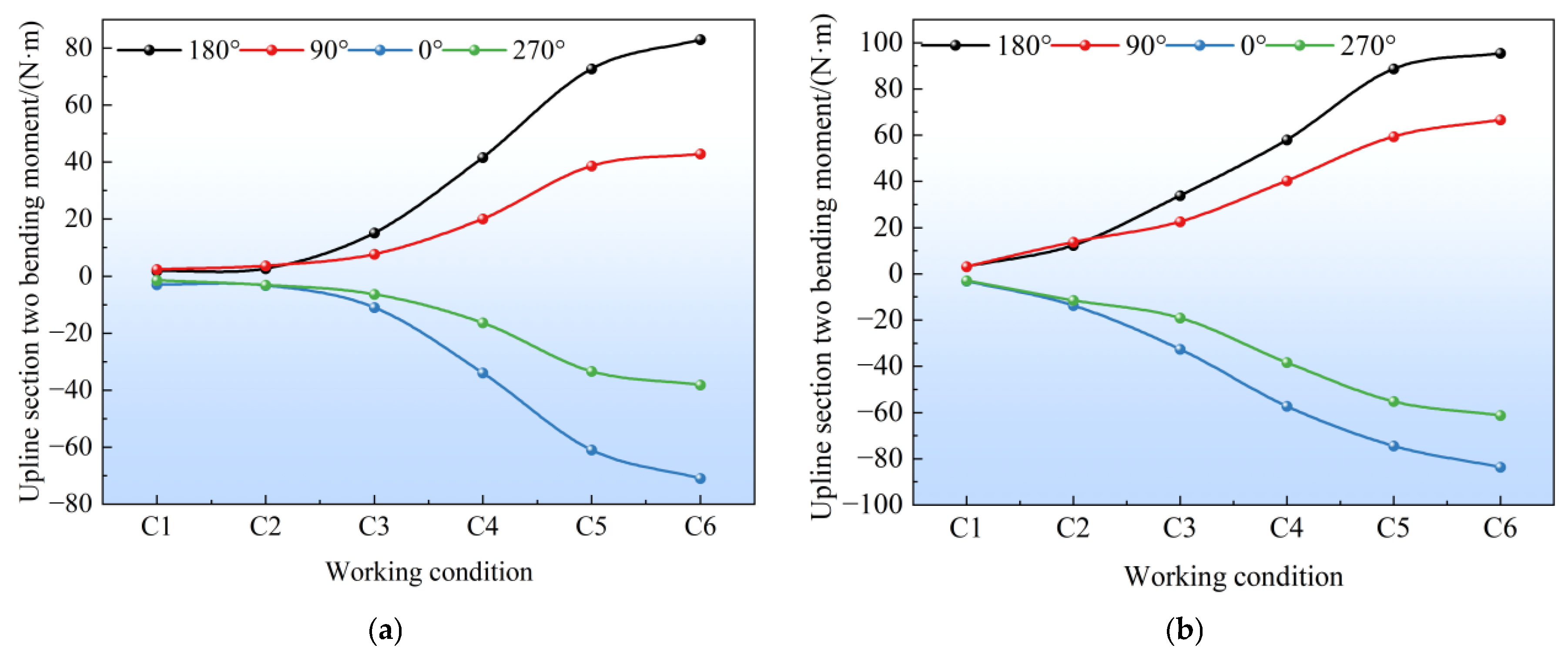
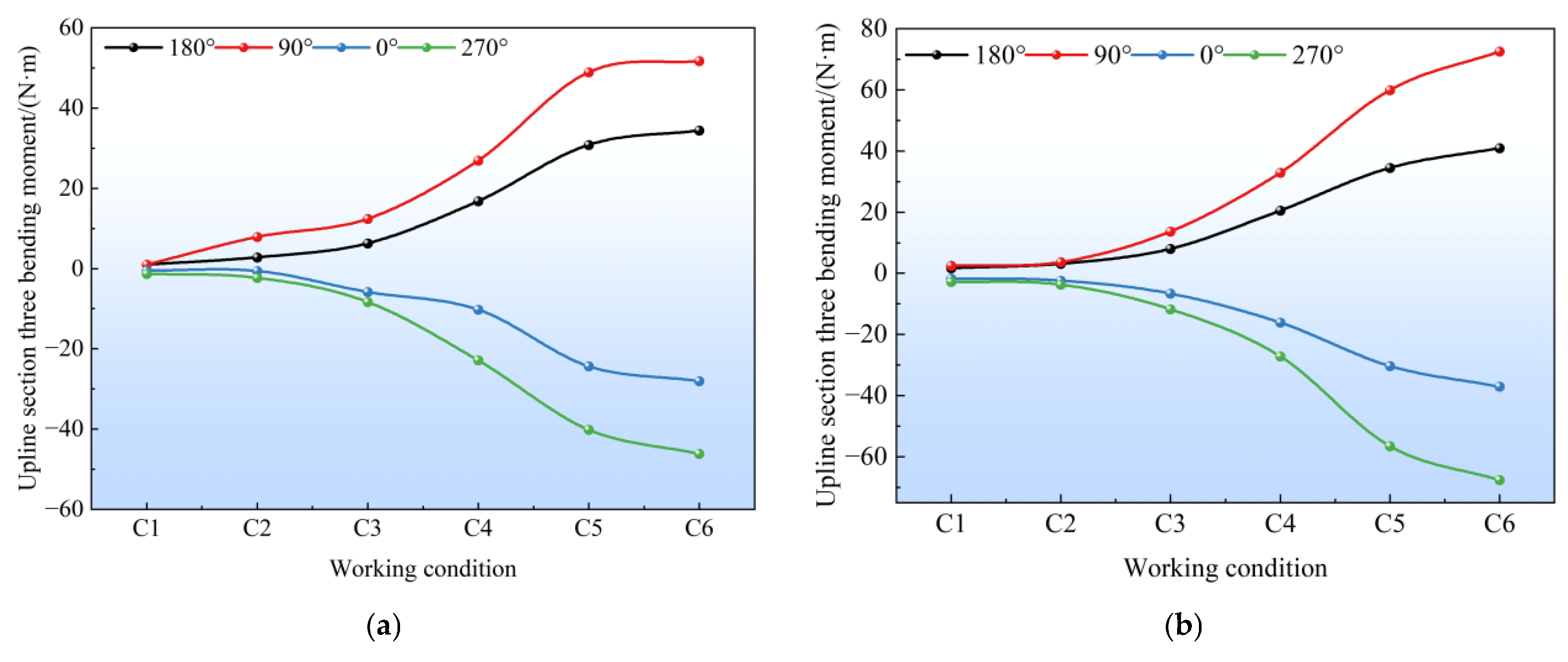
Analysis of Figure 13 and Figure 14 showed that the bending moment growth trend was consistent with that at Section 1, where the bending moments at the 180° and 0° positions (which represent horizontal deformation) increased most significantly. This indicated that horizontal deformation dominated at Section 2 of the tunnel. Similarly to Section 1, the bending moments were positive at 180° and 90°, and negative at 0° and 270°, suggesting that the tunnel still exhibited horizontal deformation toward the excavation side of the foundation pit, with upward bulging. Comparing the two types of support structures, at Section 2, the pile-anchor support structure still provided better deformation control and protection for the tunnel than the double-row pile support structure. According to the data in Figure 10 and Figure 11, for the left-side tunnel under the pile-anchor support structure, the maximum positive bending moment at Section 2 increased by 54.16 N·m compared to that at Section 1, while the maximum negative bending moment decreased by 50.05 N·m. Under the double-row pile support structure, the maximum positive bending moment at Section 2 increased by 63.68 N·m, and the maximum negative bending moment decreased by 53.83 N·m. It was evident that the bending moment increase at Section 2 was significant, which can be attributed to the more pronounced unloading effect that is closer to the excavation center. This effect also had a greater impact on the adjacent existing metro structure.
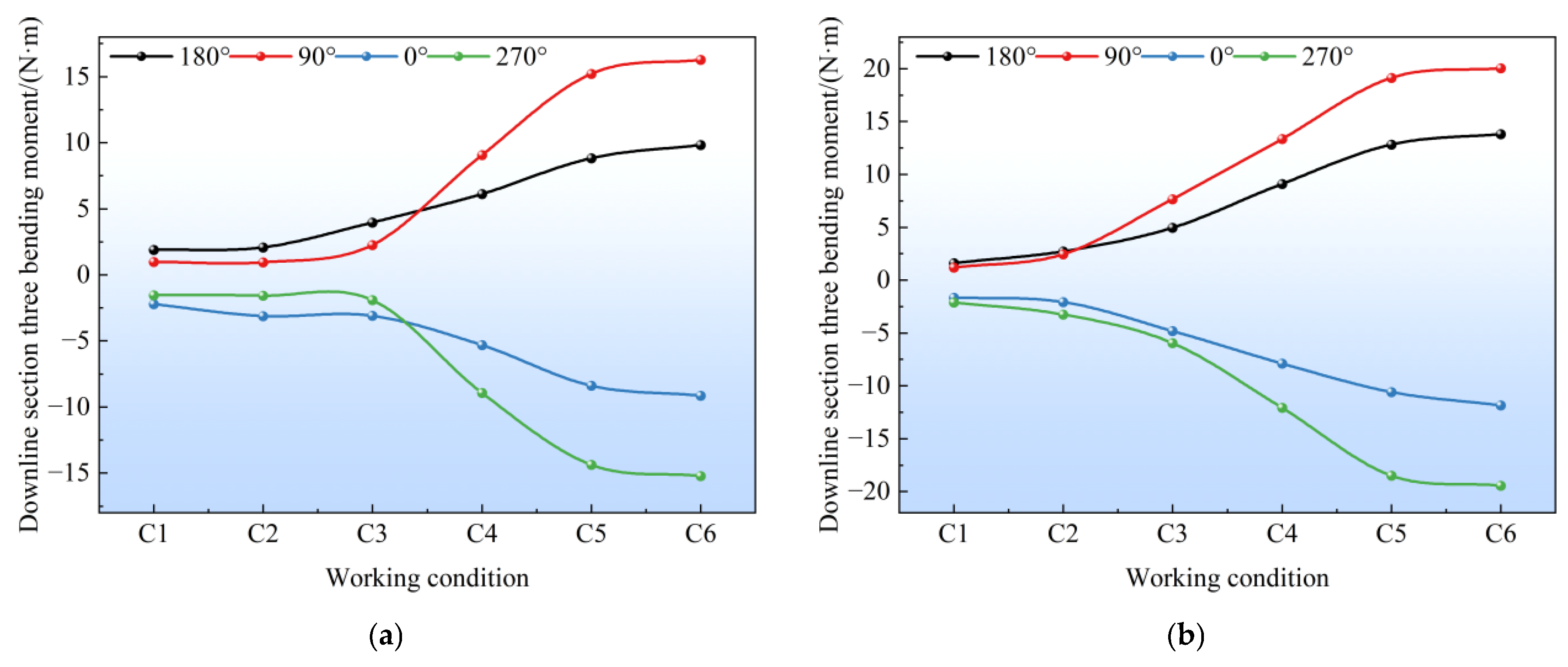
As shown in Figure 15 and Figure 16, the overall trend of the bending moment at Section 3 was similar to that of Sections 1 and 2. The maximum positive and negative bending moments of the tunnel under the double-row pile support structure were greater than those under the pile-anchor support structure. Although Section 3 was located at the center of the excavation area and should theoretically have been most affected by the excavation, the bending moment at the tunnel’s 90° crown was larger than that at the 180° arch waist, and both the maximum positive and negative bending moments were smaller than those at Section 2. This was because Section 3 was the interface section between the station and the tunnel. The stiffness of the station was much greater than that of the tunnel, so the tunnel was significantly influenced by the station at this section. The small deformation of the station restrained the deformation of the tunnel, thus its deformation was smaller than that of Section 2. The deformation at the crown was larger than that at the arch waist because the station’s uplift deformation was greater than its horizontal deformation, which in turn drove the tunnel’s uplift deformation, suppressing its horizontal deformation. From the observations at the three measurement sections, it could be concluded that the tunnel as a whole exhibited horizontal and uplift deformation towards the excavation side of the foundation pit. The uplift deformation increased gradually from the edge to the center of the excavation, while the horizontal deformation first increased and then decreased from the edge to the center of the excavation, with the maximum occurring near the center of the excavation rather than at the actual center. The strain of the station was relatively small, the strain distribution was mainly concentrated at the end of the tunnel close to the station, and the maximum value appeared at Section 2.

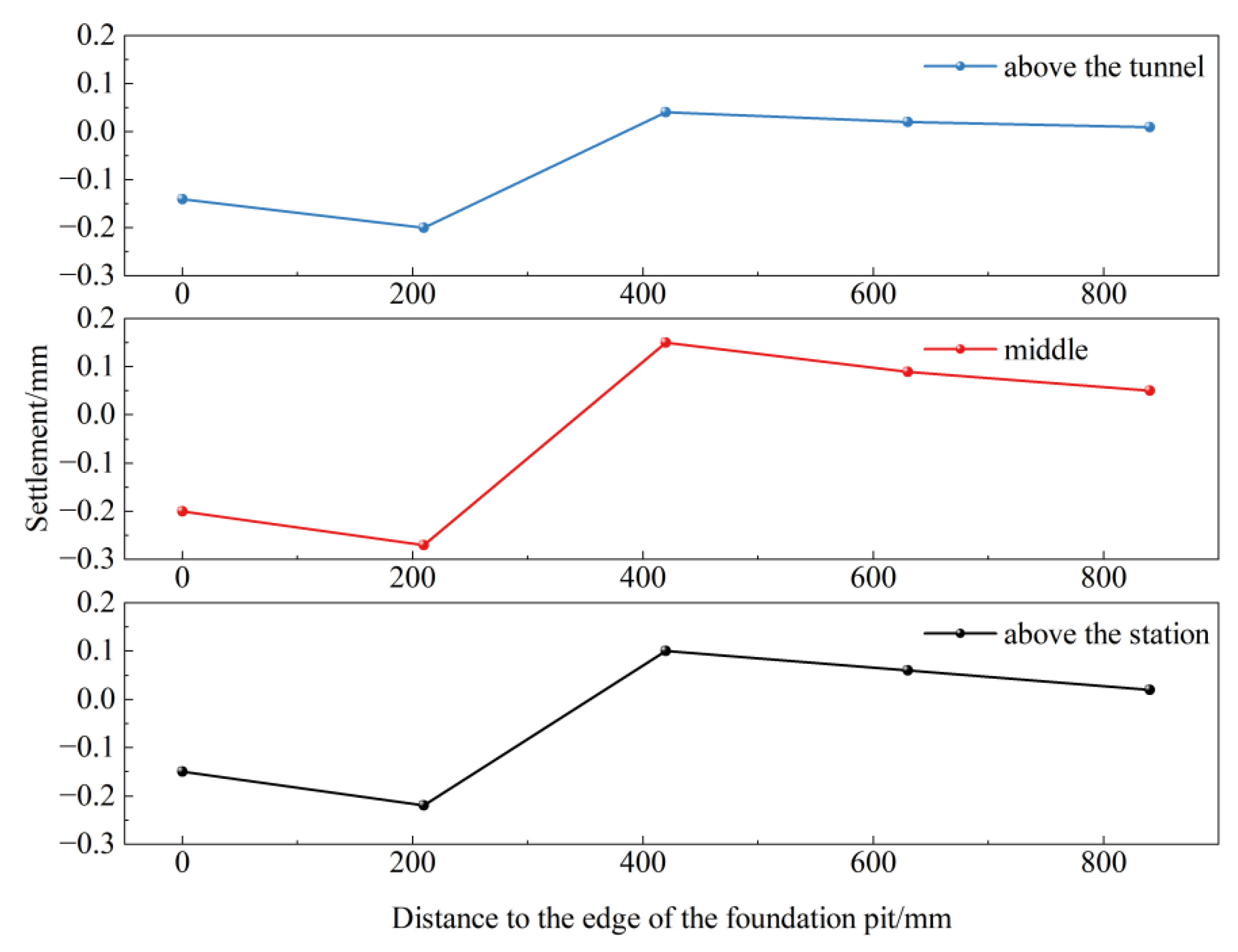
4.4. Ground Surface Settlement Above

Excavation of the foundation pit could induce surface subsidence in the surrounding area, with specific data shown in Figure 17. The upper part of the figure corresponded to the specific positions of three columns of settlement gauges. Among them, above the tunnel is Cross-section 2; above the cross-section at the junction of the tunnel and the station(middle) is Cross-section 3; and above the station is Cross-section 4. The horizontal axis represented the distance from the edge of the foundation pit, and the vertical axis represented the settlement amount. From top to bottom, the three locations were above the tunnel, above the intersection section of the tunnel and the station, and above the station. It could be observed that there was slight uplift of the soil above the tunnel and the station, which was caused by the uplift of the lower station and tunnel (caused by stress redistribution), which subsequently led to the uplift of the overlying soil. On the other hand, the soil between the metro structures and the support structure showed slight settlement. It was inferred that during the excavation of the foundation pit, the deformation of the support structure caused stress redistribution in the surrounding soil, which in turn led to soil relaxation. Additionally, the lateral movement of the soil ultimately resulted in subsidence.

4.5. Comprehensive Comparison

Table 5 presents a compilation of key numerical values to facilitate comparative analysis. It is clearly evident that the pile-anchor support system significantly outperforms the double-row pile support system.

5. Comparative Verification of Numerical Simulation

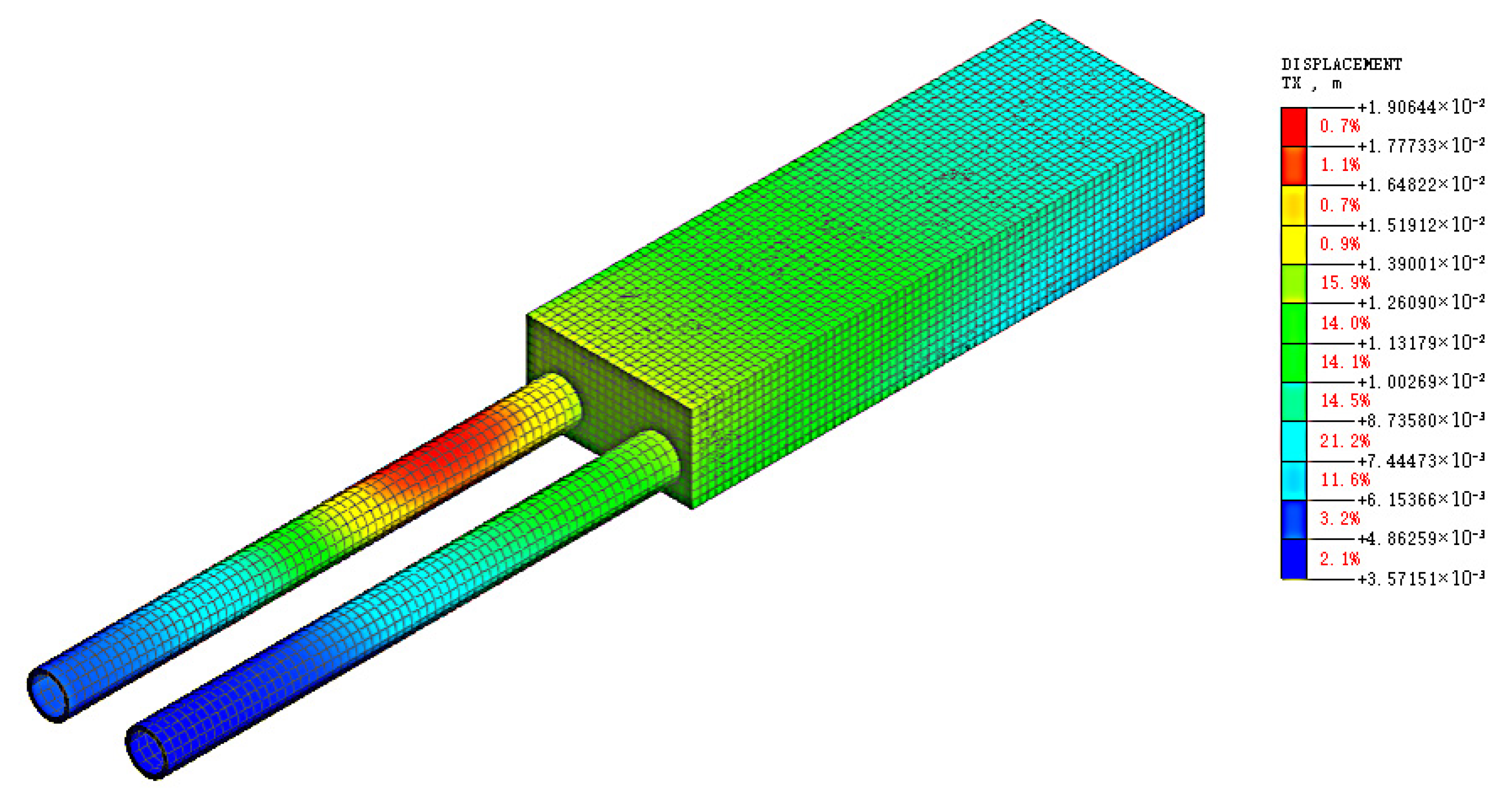
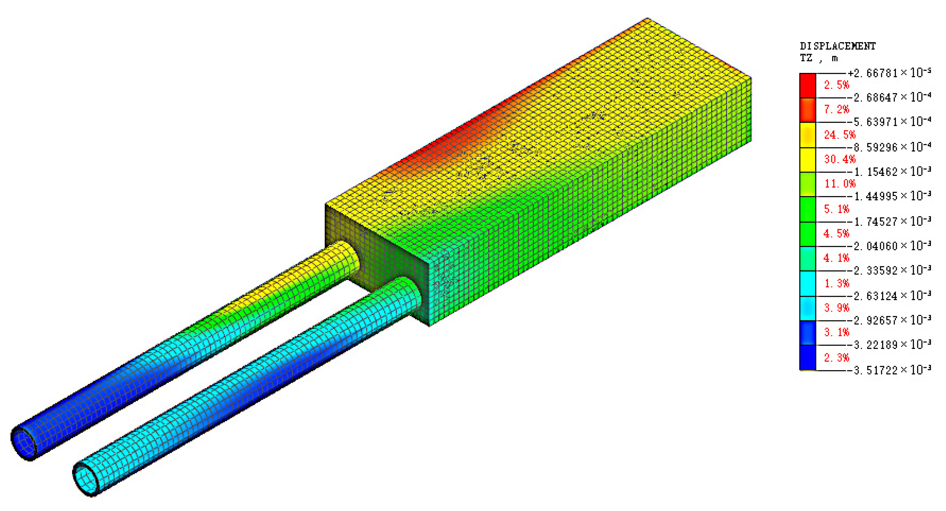
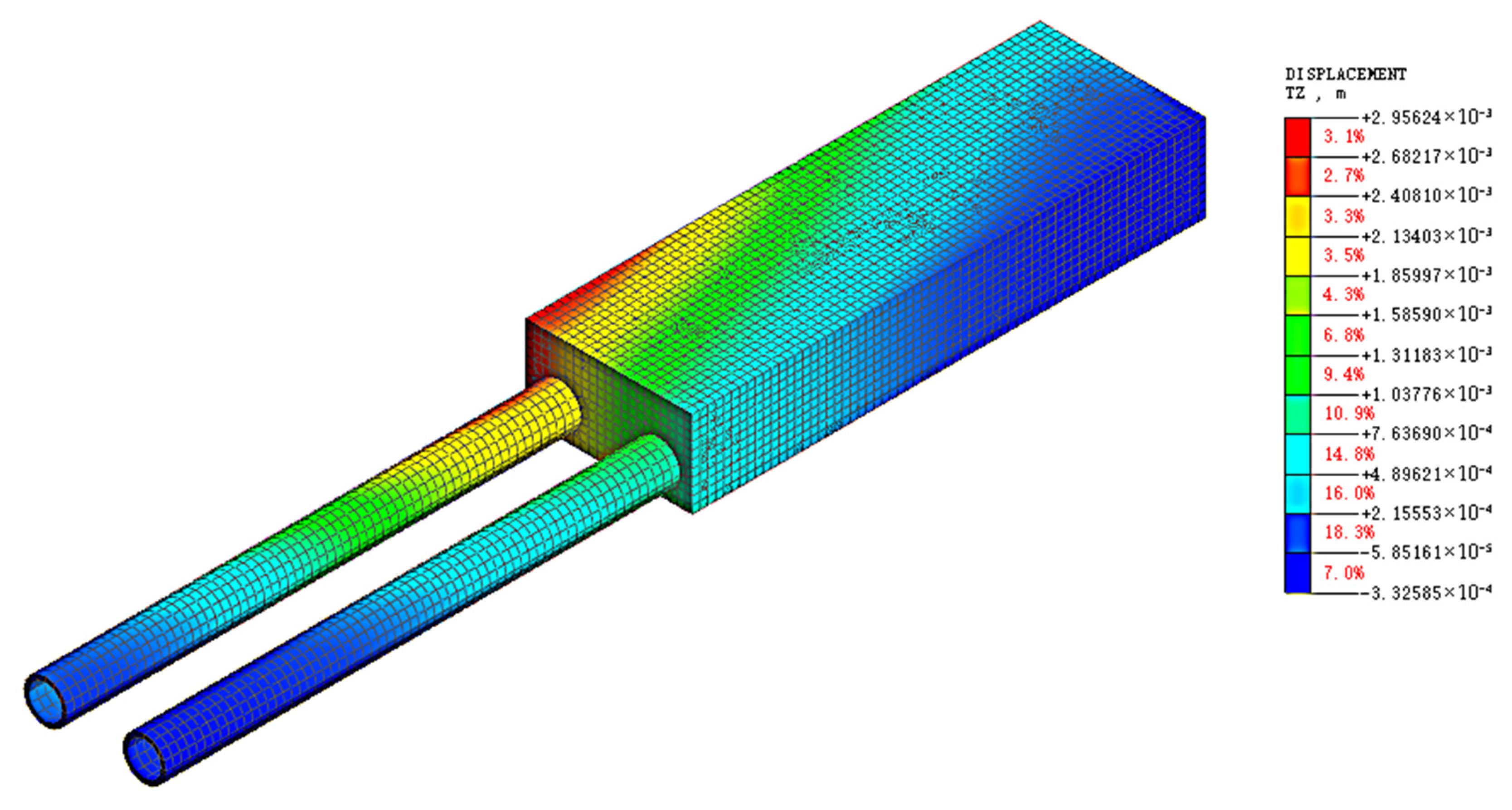
To verify the validity of the model tests, a comparative analysis of numerical simulations was conducted. The parameters of the numerical simulation model are all consistent with those of natural loess. Using Midas GTS NX (2019) software, we established a foundation pit excavation model under pile-anchor support based on the actual engineering geological conditions and positional relationship, and conducted calculations. The horizontal and vertical displacement nephograms after the completion of excavation are shown in Figure 18 and Figure 19. Among them, the legend on the right represents the displacement level corresponding to each color, and the percentages indicate the proportion level of each color in the whole.
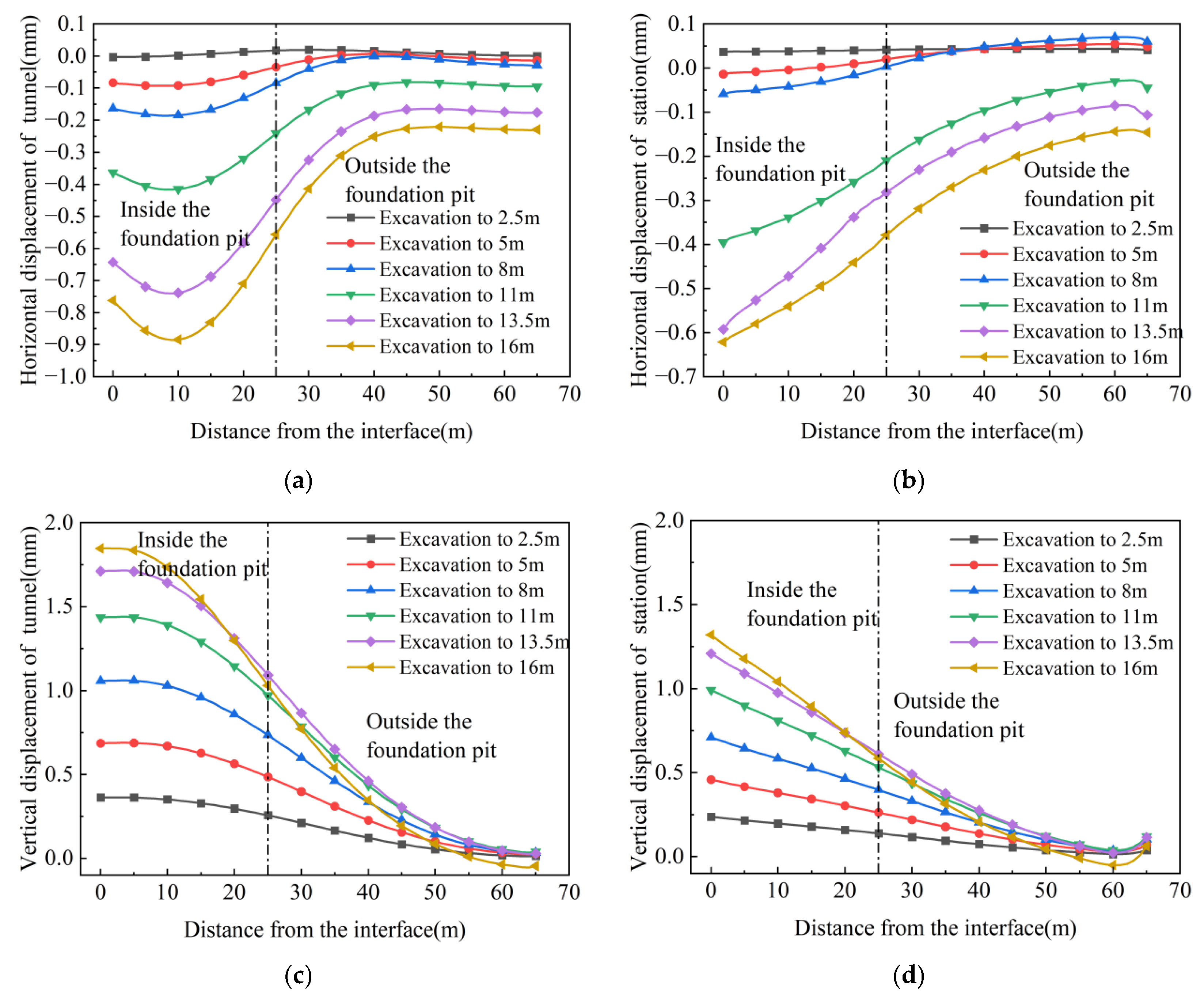
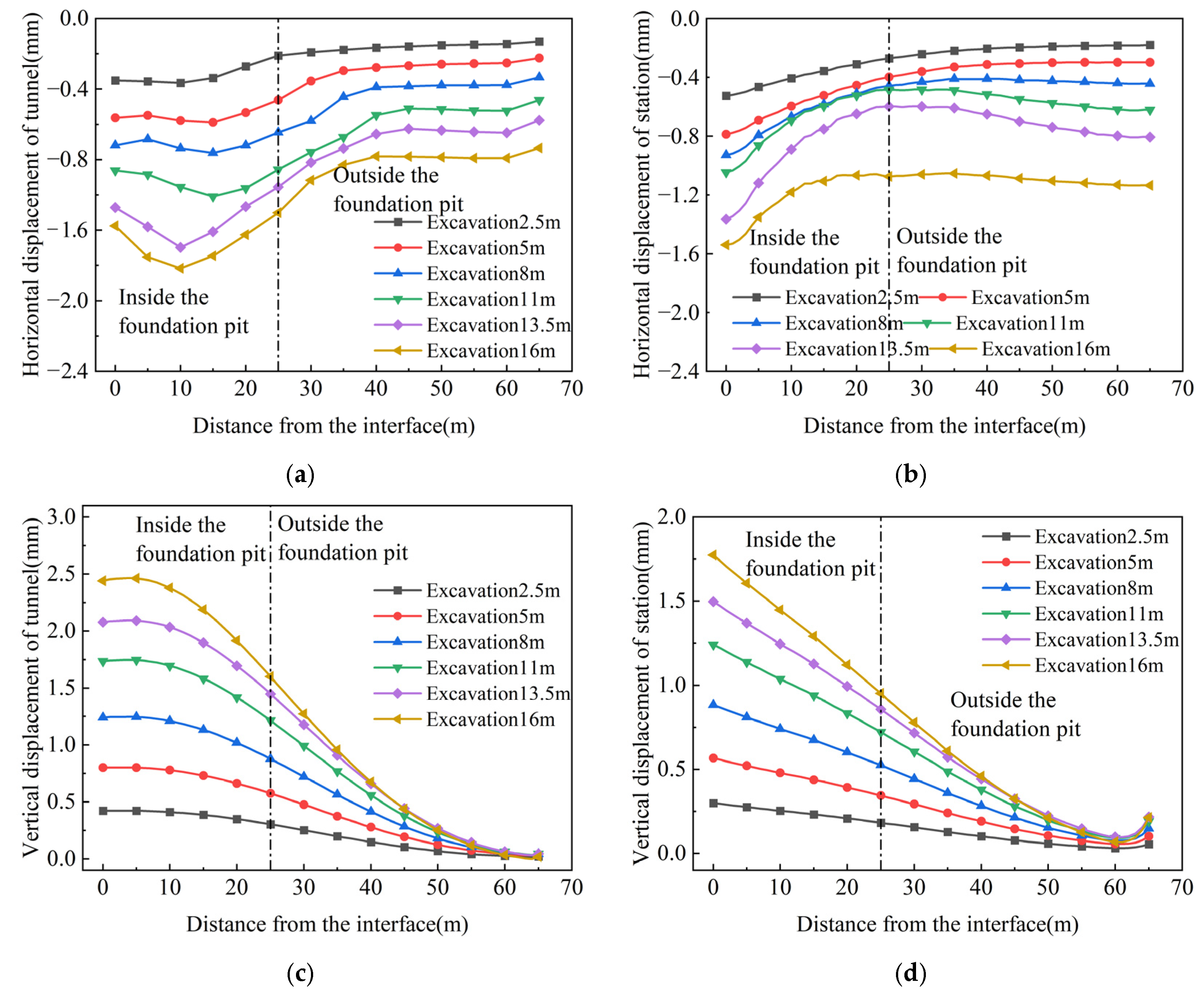
Data were extracted from the model, where positive horizontal displacement is defined as movement away from the foundation pit and positive vertical displacement as upward movement, as shown in Figure 20. The coordinate origin was set at the junction section of the tunnel and the station, with the axis extending along the longitudinal direction of the tunnel and the station. It can be seen from Figure 20a,b that the horizontal displacement of both the tunnel and the station increases with the increase in excavation depth. Additionally, the tunnel exhibits a maximum horizontal displacement at 10 m from the tunnel-station junction section; similarly, the phenomenon of reduced tunnel displacement near the junction section (influenced by the station) is observed, which is consistent with the results of the previous scaled model tests. From Figure 20c,d, it is concluded that the horizontal displacement of the station, as well as the vertical displacement of both the station and the tunnel, show a trend of increasing displacement as they approach the junction section. This is also consistent with the model test results.
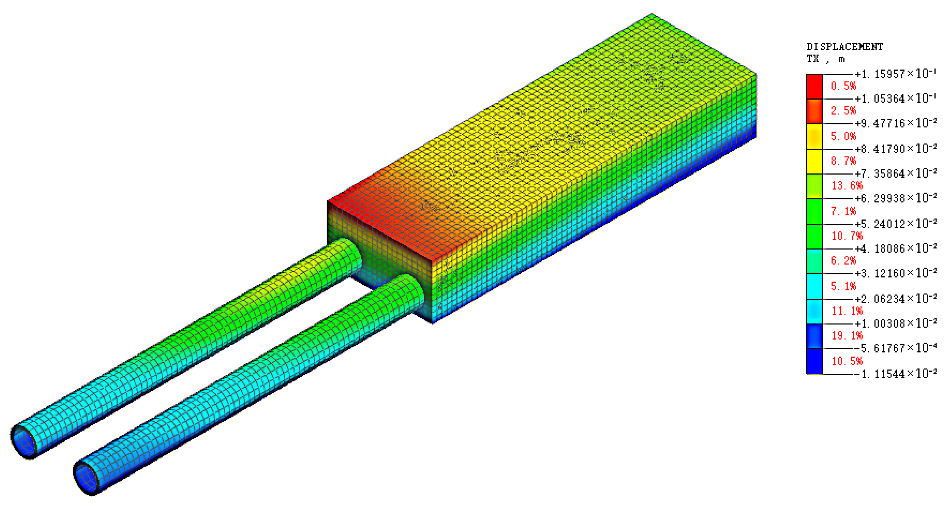
The horizontal and vertical displacement nephograms after the completion of excavation are shown in Figure 21 and Figure 22. By observing the displacement nephogram of the double-row pile support, the corresponding data were extracted, as shown in Figure 23. It can be seen from Figure 23a,b that the general trend of tunnel displacement under the double-row piles is consistent with that under the pile-anchor support. Additionally, the horizontal displacement of the station is smaller than that of the tunnel, and the displacement under the pile-anchor support structure is significantly smaller than that under the double-row pile support structure. The same applies to vertical displacement, as shown in Figure 23c,d: the maximum value occurs at the interface between the station and the tunnel in both cases, which are consistent with the results of the model test. A comprehensive comparative analysis of the numerical simulation results and the model test results can verify that the results of the model test are accurate and reliable.

6. Conclusions

1.
Under different support structures, there were differences in the influence of foundation pit excavation on the earth pressure of adjacent subway tunnels and stations: For tunnels, the variation range of earth pressure under the double-row pile support structure was significantly larger than that under the pile-anchor support structure. Both sections showed a trend of decreased earth pressure on the left side and increased earth pressure on the right side, with the earth pressure on the excavation side decreasing significantly. For stations, the variation in earth pressure under the pile-anchor support structure was smoother, resulting in less disturbance to the station. In contrast, the variation in earth pressure on the station under the double-row pile support was mainly concentrated in the excavation process corresponding to the buried depth of the station, indicating that excavation to the buried depth of the underground structure caused the greatest disturbance to it.
2.
The pile-anchor support structure withstood greater earth pressure than the double-row pile support structure. Withstanding relatively high earth pressure within a reasonable range could effectively reduce the adverse effects caused by soil displacement, exhibiting better control over the deformation of surrounding soil and less disturbance to adjacent existing subway structures. In contrast, the maximum positive and negative bending moments of the tunnel under the double-row pile support structure were both greater than those under the pile-anchor support structure. In terms of tunnel longitudinal deformation control, the pile-anchor support structure was superior, and the deformation of the left tunnel was greater than that of the right tunnel. The tunnel as a whole exhibited horizontal deformation toward the foundation pit excavation side and upward heave deformation.
3.
The bending moment increment of the tunnel’s middle section was significant. The closer to the center of the foundation pit, the more obvious the excavation unloading effect was, resulting in a greater impact on adjacent existing subway structures—with horizontal deformation as the main form. Although the tunnel-station junction was located at the foundation pit center, its horizontal deformation was smaller than that of the tunnel’s middle section due to the influence of the station’s stiffness. Moreover, the deformation at the vault was greater than that at the arch waist, which was related to the fact that the station’s heave deformation was greater than its horizontal deformation, thereby driving the tunnel to heave and inhibiting its horizontal deformation. Overall, the tunnel’s heave deformation gradually increased from the edge to the center of the foundation pit, while its horizontal deformation first increased and then decreased—with the maximum value occurring near the center rather than at the exact center.
4.
Foundation pit excavation induced settlement of the surrounding ground surface. The heave of the subway structure caused a slight heave of the soil above the tunnel and station; in contrast, the soil between the subway structure and support structure underwent slight settlement, which was due to soil relaxation caused by the unloading effect of foundation pit excavation.
5.
It can be concluded from this study that the pile-anchor support had better protective capacity for subway structures than the double-row pile support when excavating foundation pits adjacent to subway structures. Therefore, when construction conditions permit, priority should be given to selecting the pile-anchor support. Additionally, the subway operation company can be contacted to focus on strengthening and protecting the position corresponding to Section 2 in this study.
6.
While scaled model tests offer excellent economic efficiency and convenience, their test results had certain errors compared with field tests and full-scale model tests. Specifically, the measured values of stress and other parameters could not accurately reflect actual levels. However, the trends they revealed were correct and reasonable. Additionally, due to objective factors, this study had not yet considered other support forms for analysis, thus having certain limitations. The material parameters in this study are all based on natural loess, and the mutual comparison and consistency between the numerical simulation and model test results have verified the accuracy of the research. However, since this test did not consider the collapsibility of loess, it may not be well applicable to engineering projects in non-arid loess regions. In non-arid regions, attention should be paid to preventing disasters caused by loess collapsibility and high water content.
7.
Given the limitations of this study, future research can further explore the impact of foundation pit excavation in high water content loess and collapsible loess regions on adjacent existing subway stations and tunnels. This research direction has strong prospects.

Author Contributions

Conceptualization, Z.M.; Methodology, T.D.; Validation, F.H.; Resources, S.Y., L.D. and X.Z.; Data curation, M.S.; Writing—review and editing, L.D. and R.S.; Visualization, L.D.; Supervision, S.Y. All authors have read and agreed to the published version of the manuscript.

Funding

The National Natural Science Foundation of China (52168050 and 52408465); Gansu Provincial Construction Science and Technology Project (grant number: JK2024-1); China Postdoctoral Science Foundation (BX20240451 and 2024M753850); Major Science and Technology Special Project Plan (24ZDFA010).

Data Availability Statement

The data that support the findings of this study are available from the corresponding author upon reasonable request.

Acknowledgments

The authors acknowledge the support from Gansu Construction (Investment) Holding Group Co., Ltd., and Lanzhou University of Technology.

Conflicts of Interest

Authors Zhitong Mao, Tian Ding and Fengchao Hu were employed by the company Gansu Construction (Investment) Holding Group Co., Ltd. Author Rong Shu were employed by the company Gansu Academy of Building Research (Group) Co., Ltd. The remaining authors declare that the research was conducted in the absence of any commercial or financial relationships that could be construed as a potential conflict of interest.

References

  1. Zheng, G.; Zhu, H.H.; Liu, X.R.; Yang, G.H. Control of safety of deep excavations and underground engineering and its impact on surrounding environment. China Civ. Eng. J. 2016, 49, 1–24. [Google Scholar]
  2. Chang, C.T.; Sun, C.W.; Duann, S.W.; Hwang, R.N. Response of a Taipei Rapid Transit System (TRTS) tunnel to adjacent excavation. Tunn. Undergr. Space Technol. 2001, 16, 151–158. [Google Scholar] [CrossRef]
  3. Hu, Z.F.; Yue, Z.Q.; Zhou, J.; Tham, L.G. Design and construction of a deep excavation in soft soils adjacent to the Shanghai Metro tunnels. Can. Geotech. J. 2003, 40, 933–948. [Google Scholar] [CrossRef]
  4. Sharma, J.S.; Hefny, A.M.; Zhao, J.; Chan, C.W. Effect of large excavation on deformation of adjacent MRT tunnels. Tunn. Undergr. Space Technol. 2001, 16, 93–98. [Google Scholar] [CrossRef]
  5. Li, Y.; Yang, W. Analysis on influence of deep pit construction on neighboring metro tunnel. Chin. J. Undergr. Space Eng. 2013, 9, 358–364. [Google Scholar]
  6. Wang, W.D.; Shen, J.; Weng, Q.P.; Wu, J.B. Analysis and countermeasures of influence of excavation on adjacent tunnels. Chin. J. Geotech. Eng. 2006, 28, 1340–1345. [Google Scholar]
  7. Zou, W.B.; Zhang, D.M.; Cai, X.W. Numerical simulation and real time monitoring of foundation pit excavation on deformation of adjacent MRT tunnel. Chin. J. Undergr. Space Eng. 2012, 8, 1728–1731. [Google Scholar]
  8. Zheng, G.; Wei, S.W. Numerical analyses of influence of overlying pit excavation on existing tunnels. J. Cent. South Univ. Technol. 2008, 15 (Suppl. S2), 69–75. [Google Scholar] [CrossRef]
  9. Wang, Y.; Ma, H. Analysis on the Displacement of Metro Tunnel and Metro Station around the Excavation. Rock Soil Mech. 2011, 11, 5854–5857. [Google Scholar]
  10. Qi, Q.; Fang, Y. Study on influence of deep excavation and cover load on the underlying subway tunnel structure. Build. Struct. 2012, 42, 107–111. [Google Scholar]
  11. Zhang, Z.G.; Zhang, M.X.; Wang, W.D. Two-stage method for analyzing effects on adjacent metro tunnels due to foundation pit excavation. Rock Soil Mech. 2011, 32, 2085–2092. [Google Scholar]
  12. Zhou, S.H.; He, C.; Xiao, J.H. Energy method for calculating deformation of adjacent shield tunnels due to foundation pit excavation considering step between rings. China Railw. Sci. 2016, 37, 53–60. [Google Scholar]
  13. Huang, X.; Schweiger, H.F.; Huang, H. Influence of deep excavations on nearby existing tunnels. Int. J. Geomech. 2013, 13, 170–180. [Google Scholar] [CrossRef]
  14. Liang, F.Y.; Chu, F.; Song, Z.; Li, Y.S. Centrifugal model test research on deformation behaviors of deep foundation pit adjacent to metro stations. Rock Soil Mech. 2012, 33, 657–664. [Google Scholar]
  15. Hu, X. Influence of foundation pit excavation under different conditions simulating by model test on existing tunnel. Subgr. Eng. 2015, 6, 151–155. [Google Scholar]
  16. Hisatake, M.; Ohno, S.; Katayama, T.; Ohmae, Y. Effects of the ring-cut excavation method on ground displacements and stability of a tunnel face. J. Tunn. Eng. 2007, 17, 547–554. [Google Scholar]
  17. Huang, X.; Huang, H.; Zhang, D. Centrifuge modelling of deep excavation over existing tunnels. Proc. Inst. Civ. Eng.-Geotech. Eng. 2014, 167, 3–18. [Google Scholar] [CrossRef]
  18. Kim, S.H.; Burd, H.J.; Milligan, G.W.E. Model testing of closely spaced tunnels in clay. Geotechnique 1998, 48, 375–388. [Google Scholar] [CrossRef]
  19. Xu, S.; Zhang, Q.; Zhang, W.; Zhang, Y.; Wang, Z. Influences of construction of foundation pits on deformation of adjacent operating tunnels in whole process based on monitoring data. Chin. J. Geotech. Eng. 2021, 43, 804–812. [Google Scholar]
  20. Zhang, X.; Su, H.; Jiang, B. Influence of Foundation Pit Excavation on Adjacent Subway Tunnel. Shanghai Geol. 2008, 2, 27–29+34. [Google Scholar]
  21. Guang, L.; Xu, C.; Ke, W.; Di, H.; Zhang, G.; Yang, W. Analysis of horizontal pipeline deformation caused by shield tunnelling. J. Civ. Environ. Eng. 2020, 42, 54–62. [Google Scholar]
  22. Lo, K.Y.; Ramsay, J.A. The effect of construction on existing subway tunnels—A case study from Toronto. Tunn. Undergr. Space Technol. 1991, 6, 287–297. [Google Scholar] [CrossRef]
  23. Yu, J.-X.; Ye, J.-N.; Kuang, Z.-R.; Zhang, W.-B.; Cheng, H.-Z. Measurement analysis of deformation in metro tunnels adjacent to large-scale foundation pit excavation in soft soil. J. Railw. Sci. Eng. 2025, 1–11. [Google Scholar] [CrossRef]
  24. Zhang, Z.G.; Chen, Y.J.; Wei, G. Time-dependent analysis on deformation of adjacent tunnel with small curvature radius induced by excavation in soft soil. Chin. J. Geotech. Eng. 2025, 47, 1793–1803. [Google Scholar]
  25. Klar, A.; Vorster, T.E.B.; Soga, K.; Mair, R.J. Soil—Pipe interaction due to tunnelling: Comparison between Winkler and elastic continuum solutions. Géotechnique 2005, 55, 461–466. [Google Scholar] [CrossRef]
  26. Attewell, P.B.; Woodman, J.P. Predicting the dynamics of ground settlement and its derivitives caused by tunnelling in soil. Ground Eng. 1982, 15, 13. [Google Scholar]
  27. Vorster, T.E.; Klar, A.; Soga, K.; Mair, R.J. Estimating the effects of tunneling on existing pipelines. J. Geotech. Geoenviron. Eng. 2005, 131, 1399–1410. [Google Scholar] [CrossRef]
  28. Zhen-Ke, H. Research on the Construction Design of Overlying Foundation Pit of Shield Tunnel. J. Railw. Eng. Soc. 2024, 41, 109–113+118. [Google Scholar]
  29. Rui, J.; Ji, Y.; Zhang, G.; Li, H. Analysis of Influence of Foundation Pit Excavation on Adjacent Tunnel in Structured Clays Under Different Degrees of Previous Construction Disturbance. J. Tianjin Univ. (Sci. Technol.) 2024, 58, 801–809. [Google Scholar]
  30. Cai, R.; Li, M.; Ma, F.; Li, Z.; Wang, H.; Cai, H. Circumferential forces and deformations of shield tunnels due to lateral excavation. Chin. J. Geotech. Eng. 2023, 45, 24–32. [Google Scholar]
  31. Huang, M.H.; Zhong, Y.X.; Lu, J.B. Deformation analysis of underlying shield tunnel induced by foundation pit excavation based on discontinuous foundation beam model. Rock Soil Mech. 2025, 46, 492–504. [Google Scholar]
  32. Feng, G.H.; Xu, C.J.; Zheng, M.W.; Xue, W.J.; Yang, K.F.; Guan, L.X. Study of longitudinal deformation of existing underlying tunnel due to above excavation considering shear deformation of tunnel. J. China Railw. Soc. 2022, 44, 132–141. [Google Scholar]
  33. Wei, G.; Mu, Z.Y.; Qi, Y.J.; Guo, B.L.; Xiang, P.F. Deformation protection of shield tunnels next to foundation pits by isolation piles considering formation loss. Chin. J. Geotech. Eng. 2024, 46, 480–489. [Google Scholar]
  34. Zhang, Z.W.; Liang, Q.Z.; Gao, K.; Li, Z.C.; Xiao, M.Z.; Guo, Y.; Sheng, W.; Wu, W.B. Analysis of longitudinal displacement of existing shield tunnel due to construction of above-crossing new tunnel considering the weakening of circumferential joint. Chinese Chin. J. Rock Mech. Eng. 2022, 41, 2955–2970. [Google Scholar]
  35. Xu, S.F.; Yu, J.H.; Wang, Z. A computational method for the lateral displacement of tunnels caused by foundation pit excavation based on non-limit earth pressure. J. Zhejiang Univ. Technol. 2024, 52, 312–318. [Google Scholar]
  36. Ying, H.W.; Cheng, K.; Yu, J.L.; Xu, R.Q.; Qiu, Z.J.; Zhang, X.B.; Qin, J.S.; Lou, C.H. Prediction of shield tunnel displacement due to adjacent basement excavation considering continuous deformation of ground. J. Zhejiang Univ. (Eng. Sci.) 2021, 55, 318–329. [Google Scholar]
  37. Zhou, Z.; Chen, S.; Tu, P.; Zhang, H. Coupling method for analyzing the influence on existing tunnel due to adjacent foundations pit excavation. Rock Soil Mech. 2018, 39, 1440–1449. [Google Scholar]
  38. Guan, L.X.; Xu, C.J.; Luo, Q.; Ding, H.B.; Ke, W.H. Underlying tunnel deformation caused by excavation and dewatering of foundation pit based on kerr foundation model. Eng. Mech. 2023, 42, 145–153. [Google Scholar]
  39. Liang, R.Z.; Zhang, Z.W.; Li, Z.C. Simplified solutions for longitudinal deformation of shield tunnels considering influences of circumferential joints. Chin. J. Geotech. Eng. 2024, 46, 254–263. [Google Scholar]
  40. Xu, C.; Hu, X.L.; He, C.C.; Xu, Y.; Zhou, C. Development and application of similar material for reservoir landslide model test. Rock Soil Mech. 2018, 39, 4287–4293. [Google Scholar]
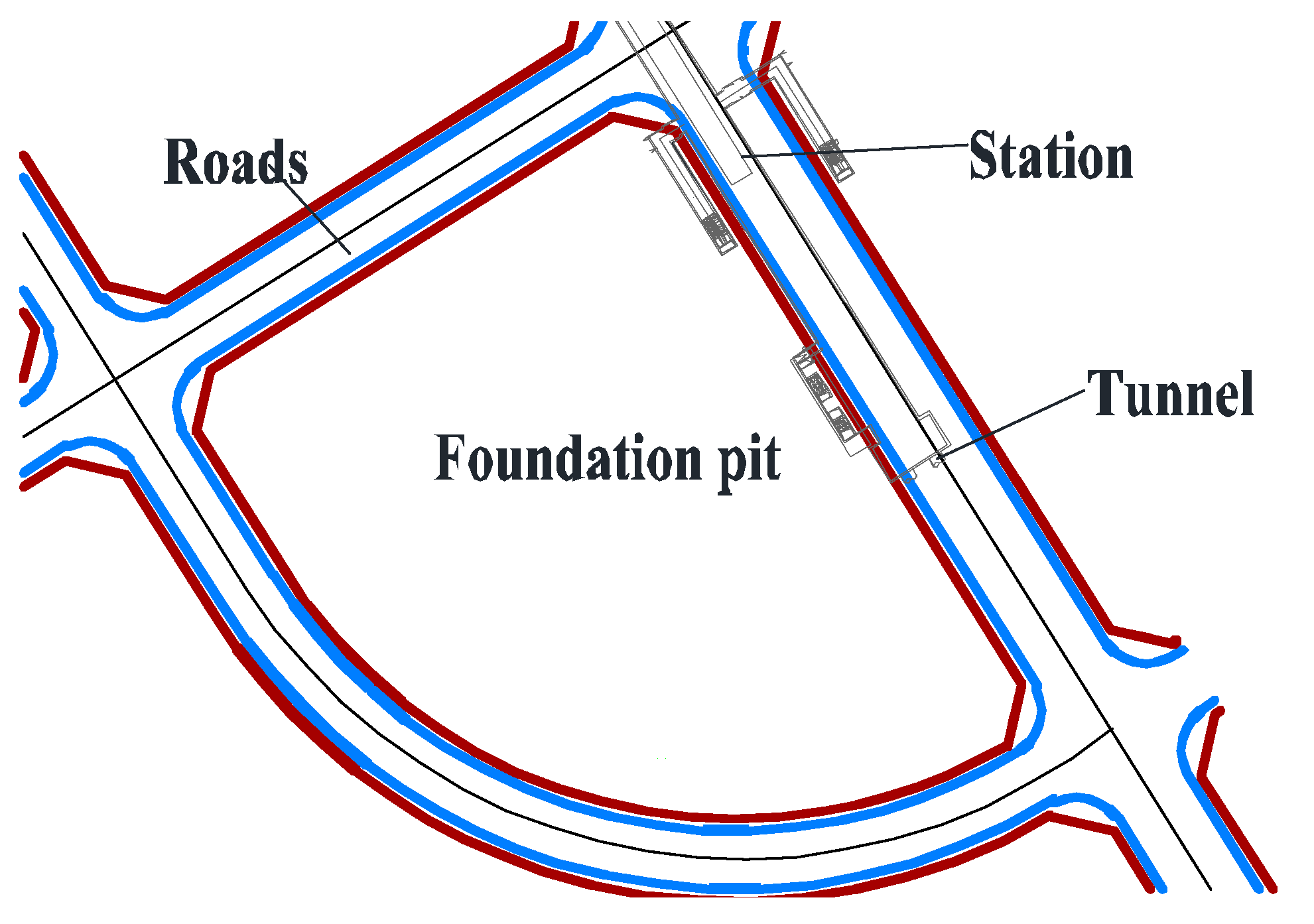
Figure 1. Planar Relationship between the Foundation Pit and the Existing Metro.
Buildings 15 04178 g001
Figure 2. Test Steps.
Buildings 15 04178 g002
Figure 3. Fitted curve of Loess direct shear test.
Buildings 15 04178 g003
Figure 4. Physical map of the model box: (a) Model box; (b) Layout of components.
Buildings 15 04178 g004
Figure 5. Modeling material: (a) Station and tunnel; (b) Pile.
Buildings 15 04178 g005
Figure 6. Test arrangement: (a) Sectional view of Pile-Anchor support structure; (b) Sectional view of Double-row pile support structure; (c) Plan view of Pile-Anchor support structure; (d) Plan view of Double-row pile support structure; (e) Detailed layout drawing of components.
Buildings 15 04178 g006
Figure 7. Earth pressure of tunnel at Section 3: (a) Pile-Anchor; (b) Double-Row Pile.
Buildings 15 04178 g007
Figure 8. Earth pressure of tunnel at Section 2: (a) Pile-Anchor; (b) Double-Row Pile.
Buildings 15 04178 g008
Figure 9. Earth pressure on the side wall of the station at Section 4: (a) Pile-Anchor; (b) Double-Row Pile.
Buildings 15 04178 g009
Figure 10. Pile-soil pressure: (a) Pile-Anchor; (b) Double-Row Pile.
Buildings 15 04178 g010
Figure 11. Bending moment of left tunnel at Section 1: (a) Pile-Anchor; (b) Double-Row Pile.
Buildings 15 04178 g011
Figure 12. Bending moment of right tunnel at Section 1: (a) Pile-Anchor; (b) Double-Row Pile.
Buildings 15 04178 g012
Figure 13. Bending moment of left tunnel at Section 2: (a) Pile-Anchor; (b) Double-Row Pile.
Buildings 15 04178 g013
Figure 14. Bending moment of right tunnel at Section 2: (a) Pile-Anchor; (b) Double-Row Pile.
Buildings 15 04178 g014
Figure 15. Bending moment of left tunnel at Section 3: (a) Pile-Anchor; (b) Double-Row Pile.
Buildings 15 04178 g015
Figure 16. Bending moment of right tunnel at Section 3: (a) Pile-Anchor; (b) Double-Row Pile.
Buildings 15 04178 g016
Figure 17. Settlement around the foundation pit.
Buildings 15 04178 g017
Figure 18. Horizontal Displacement Nephogram of Pile-Anchor Support.
Buildings 15 04178 g018
Figure 19. Vertical Displacement Nephogram of Pile-Anchor Support.
Buildings 15 04178 g019
Figure 20. Numerical Simulation Results of the Pile-Anchor Support: (a) Tunnel Horizontal Displacement; (b) Station Horizontal Displacement; (c) Tunnel Vertical Displacement; (d) Station Vertical Displacement.
Buildings 15 04178 g020
Figure 21. Horizontal Displacement Nephogram of Double-Row Pile Support.
Buildings 15 04178 g021
Figure 22. Vertical Displacement Nephogram of Double-Row Pile Support.
Buildings 15 04178 g022
Figure 23. Numerical Simulation Results of the Double-Row Pile Support: (a) Tunnel Horizontal Displacement; (b) Station Horizontal Displacement; (c) Tunnel Vertical Displacement; (d) Station Vertical Displacement.
Buildings 15 04178 g023
Table 1. Model Similarity Relations.
Serial NumberPhysical QuantitySimilarity RelationModel
1Strain ( ε ) C ε = 1.0 1
2Length ( l ) C l 1/50
3Area ( s ) C s = C l 2 1/2500
4Stiffness (E) C E 1/50
5Flexural rigidity ( E I ) C E C l 4 1/312,500,000
6Density ( ρ ) C ρ 1
7Mass ( m ) C ρ C L 3 1/125,000
8Poisson’s ratio ( μ ) C μ = 1.0 1
9Compressive stiffness ( E A ) C E A = C E C l 2 1/125,000
10Prestress ( F ) C F = C E C l 2 1/125,000
11Cohesion ( c ) C c = C l 1/50
12Displacement (u) C u = C l 1/50
Table 2. Material parameters.
NumberObjectMaterialElastic Modulus of Prototype MaterialElastic Modulus
1PilePE30 GPa500 MPa
2Anchor Cableiron wire200 GPa180 GPa
3TunnelPVC30 GPa2.0 GPa
Table 3. Construction Conditions.
Construction ConditionsNO.Construction ScopeExcavation Depth (cm)
1C0Initial state0
2C1First excavation5
3C2Second excavation5
4C3Third excavation, lock the second layer of anchor cables6
5C4Fourth excavation, lock the second layer of anchor cables6
6C5Fifth excavation5
7C6Sixth excavation, lock the second layer of anchor cables5
Table 4. Test working condition.
NumberSupport StructureExcavation Depth/cmFoundation Pit Width/cm
1Pile-Anchor Support3250
2Double-row pile support3250
Table 5. Results Comparison.
Support StructurePile-Anchor SupportDouble-Row Pile Support
Maximum Value of Tunnel Earth Pressure Change0.53 kPa4.18 kPa
Maximum Value of Station Earth Pressure Change2.44 kPa7.92 kPa
Maximum Value of Pile Earth Pressure Change3.75 kPa1.95 kPa
Maximum Value of Tunnel Bending Moment Change83.02 N·m95.40 N·m
Maximum Value of Station Bending Moment Change53.65 N·m78.48 N·m
Disclaimer/Publisher’s Note: The statements, opinions and data contained in all publications are solely those of the individual author(s) and contributor(s) and not of MDPI and/or the editor(s). MDPI and/or the editor(s) disclaim responsibility for any injury to people or property resulting from any ideas, methods, instructions or products referred to in the content.