Article

On-Site Welding Research for High-Strength S690 Steel

China State Construction Engineering (Hong Kong) Ltd., 28/F, China Overseas Building, 139 Hennessy Road, Wan Chai, Hong Kong SAR, China
*
Author to whom correspondence should be addressed.
Buildings 2025, 15(22), 4102; https://doi.org/10.3390/buildings15224102
Submission received: 15 October 2025 / Revised: 7 November 2025 / Accepted: 9 November 2025 / Published: 14 November 2025
(This article belongs to the Special Issue Non-linear Behavior and Design of Steel Structures)

Abstract

High-strength S690 steel is becoming increasingly popular in Hong Kong because of its numerous advantages in terms of mechanical properties and cost-effectiveness. Compared to normal-strength steel, the welding parameters such as preheat temperature, inter-pass temperature, and heat input energy of high-strength S690 steel should be controlled more strictly; additional post-weld heat treatment should be carried out for hydrogen diffusion in some situations. These strict requirements pose challenges to welding operations at construction sites. In Hong Kong, all field connections of high-strength S690 steel components are made using bolted connections, and there are currently no precedents for welded connections on site. To verify the reliability of on-site welding and optimize the welding process to facilitate operation, on-site welding tests of high-strength S690 steel with various welding procedures were conducted. These welding tests were first performed on the steel plates, followed by tests on the H-section steel components, to examine the mechanical reliability of the welding connections under tension and compression. The effects of heat input energy, welding joints, post-weld heat treatment, and wind blocking measures on welding quality and welding efficiency were studied.

1. Introduction

The use of high-strength steel such as S690 has been a key area of innovation that the construction industry has been actively exploring for a long time [1,2,3,4,5,6,7]. The high production cost of high-strength steel and the lack of a comprehensive understanding of its mechanical properties and welding properties hindered its large-scale application for many years.
Due to technological advancements in high-strength steel production, the production costs of high-strength S690 steel have significantly decreased [8]. The stringent welding requirements for high-strength steel and the mechanical properties of structural members made up of high-strength steel have been widely studied [9,10]. Furthermore, the strength model and low-cycle fatigue properties for welded joints of high-strength steel have also been studied [11,12]. Based on these innovative research results, design criteria were proposed and incorporated into the Code of Practice for the Structural Use of Steel 2011 (2023 Edition) [13].
As a result of the aforementioned decrease in production costs and the advancement in research, high-strength steel has been more widely used in construction projects in recent years. The double-arch steel bridge of the Cross-Bay Line in the Tseung Kwan O area [14] and the Redevelopment of Kowloon Tsai Swimming Pool Complex are two outstanding engineering cases of using high-strength steel in Hong Kong, as shown in Figure 1. These two projects brought considerable benefits in terms of cost, time, productivity, safety, carbon embodiment, etc.
Generally, there are three delivery conditions for high-strength steels: a normalized rolled process, a quenched and tempered (QT) process, and a thermomechanical controlled rolled process (TCMP) [15]. Research on common production processes for steel materials indicated that high-strength S690 steel materials are typically produced using the QT process [9,16]. Furthermore, for S690 grade steel, only QT-processed steel materials are covered in the Code of Practice for the Structural Use of Steel 2011 (2023 Edition) in Hong Kong. Therefore, in this paper, the term “S690” specifically refers to “S690-QT” steel manufactured using the QT process. The production process of S690 steel makes its mechanical properties susceptible to heating–cooling cycles during welding. Some of the most important parameters in the welding procedure of high-strength S690 steel are presented below [15,17].
(1)
Preheating temperature.
An appropriate pre-heating process should be conducted to avoid hydrogen cracking (also known as cold cracking). The preheating temperature range is influenced by various factors, such as the composition of the base metal and weld metal, plate thickness, hydrogen content of the welding consumables, heat input energy during welding, and stress levels.
(2)
Heat input energy and inter-pass temperature.
Insufficient heat input energy and low inter-pass temperature can result in an excessively short cooling time. This may lead to an elevated hardness in the heat-affected zone, increasing the risk of cracking. Conversely, excessive heat input energy and high inter-pass temperature can prolong the cooling time, which may promote phase transformation and re-crystallization, significantly reducing the mechanical properties of the steel plate.
(3)
Post-weld heat treatment (PWHT).
In case of a high risk of cold cracking, hydrogen release should be accelerated by proper post-weld heat treatment.
For comparison, welding parameters of high-strength S690 steel and normal-strength S355 steel previously used in actual projects are listed in Table 1.
As shown in Table 1, the welding temperature and the heat input energy control during welding of S690 are stricter than those during welding of S355 steel. Furthermore, when on-site welding is carried out, PWHT is difficult to perform, and environmental factors including wind speed and air humidity influence the welding quality significantly.
Due to these difficulties during on-site welding, the welding process of S690 steel is conducted in a factory for construction projects in Hong Kong, such as the double-arch steel bridge of the Cross-Bay Line in the Tseung Kwan O area [8], as well as the Redevelopment of Kowloon Tsai Swimming Pool Complex. The on-site splicing of high-strength S690 steel components is implemented by bolt connection. There is no validated on-site welded S690 field splice existing in HK, and this study provides the first verification. To assess welding reliability in the challenging environments of construction sites and to optimize on-site welding procedures for improved efficiency, we conducted a series of tests on high-strength steel S690 and analyzed the impact of various factors, including heat input energy, welding joints, post-weld heat treatment, and wind-blocking measures, on the quality of the welds and overall welding efficiency. A research team from the Hong Kong Polytechnic University (PolyU) was invited to supervise the tests.

2. Research Focuses

The research focuses are as follows.
(1)
As stated above, the heat input energy is one of the key welding parameters. To gain the practicable range of heat input energy and expand the welder’s operating flexibility, 4 heat input energy values were studied.
(2)
Additionally, two joint details were employed to investigate their effects on welding quality and efficiency, aiming to identify the optimal joint detail.
(3)
Traditionally, it is recommended to perform PWHT to accelerate hydrogen release for the welding of high-strength steel [17,18,19]. Various PWHT processes for diffusing hydrogen, which were recommended or adopted, are listed in Table 2. PWHT for shop welding was typically performed with temperature-controlled heaters through thermal radiation or conduction, making on-site operation challenging.
On the other hand, some researchers also reported that the hydrogen cracking of high-strength steel could be prevented by using low-hydrogen weld metal and ensuring proper preheating and inter-pass temperatures, without performing PWHT [20]. Therefore, the PWHT may be helpful but not necessary for the welding of high-strength S690 steel. The on-site welding tests were performed without PWHT to investigate the potential elimination of PWHT, aiming to simplify the welding procedure.
(4)
Differing from the in-shop welding, on-site welding could be impacted significantly by wind. An effective wind block must be implemented when the wind velocity is high [21,22]. In this study, an easily installable and removable wind block was proposed, and the effectiveness of blocking wind was studied.
Full penetration butt weld (FPBW) is commonly used in on-site welded splices for many types of structural components such as truss members, steel columns, and steel piles. Considering these common application scenarios listed above, the on-site welding procedures and qualities of FPBW between high-strength S690 plates were explored. As the butt welds in splices of truss members, steel columns, and steel piles mostly bear axial forces, the axial tension resistances of welding joints and compression resistances of welded members were tested.

3. On-Site Welding Test Methodology

The chemical compositions and mechanical properties of materials are summarized in Table 3 and Table 4. The steel plates were manufactured according to EN 10025-6:2019 [23], while the welding wires complied with EN ISO 16834:2012 [24]. The GMAW process was adopted and the weld wire diameter is 1.2 mm.

3.1. Test Methodology for Tensile Resistances

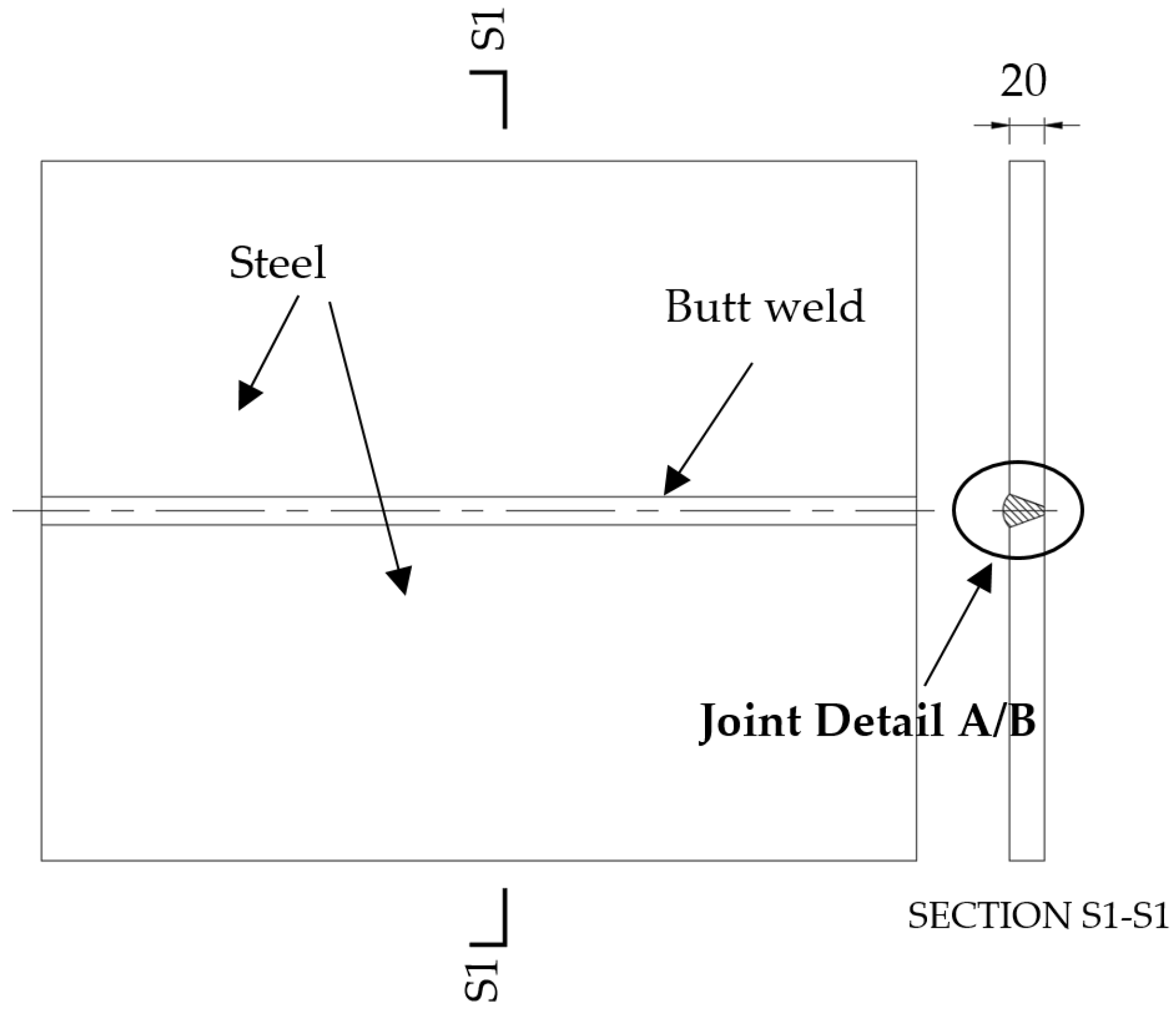
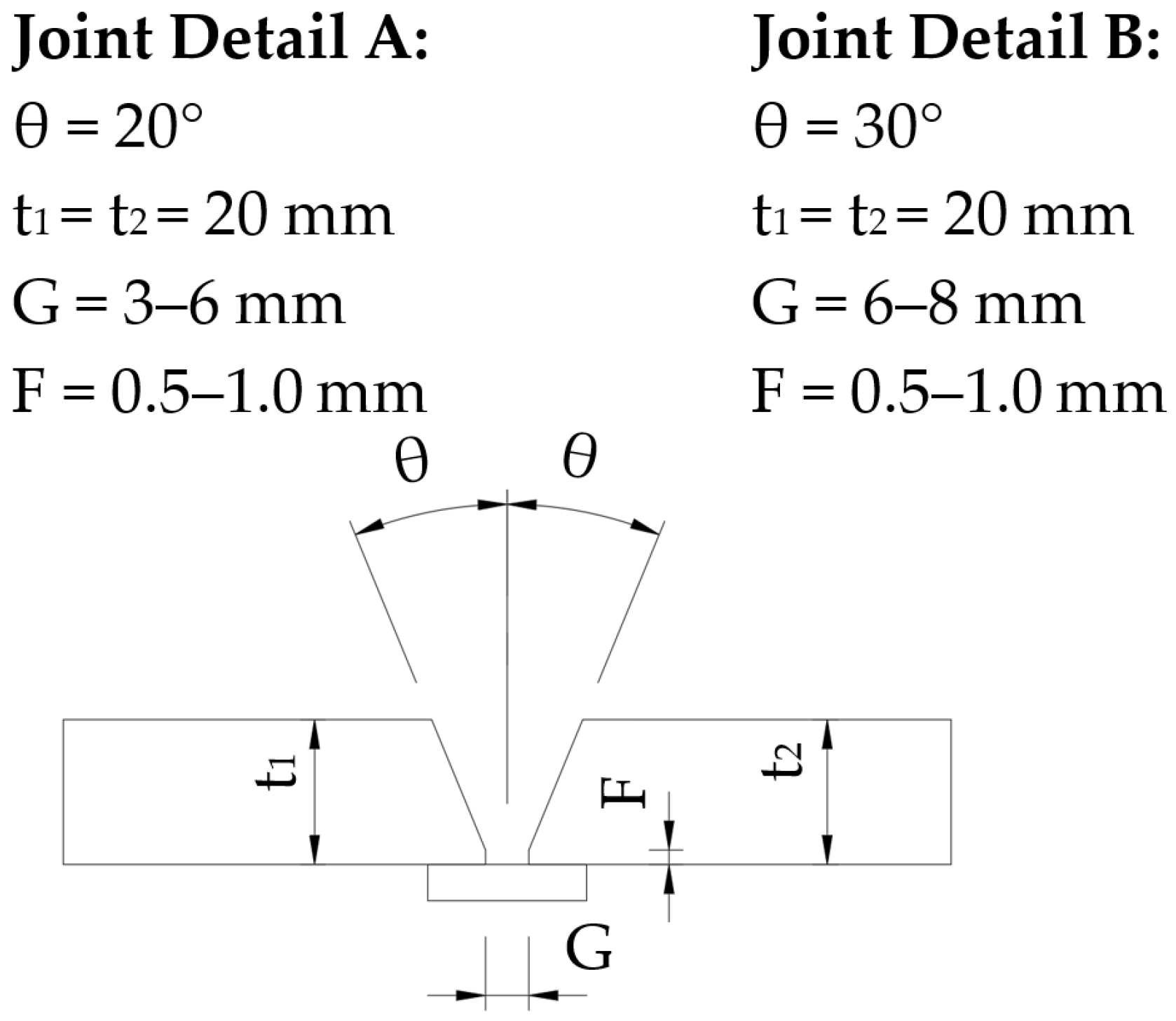
Two steel plates were butt welded into a welded section to examine the weld quality, as shown in Figure 2. Three series (named as “Series I”, “Series II”, and “Series III”) of on-site welding for tensile tests were conducted, each with different weld heat inputs and joint details. Series I had a target weld heat input of 1.0 kJ/mm, Joint Detail A, and the corresponding welded section was named BW10A. Series II also had a target weld heat input of 1.0 kJ/mm, but with Joint Detail B, and the corresponding welded section was named BW10B. In contrast, Series III included three different target weld heat inputs: 0.7 kJ/mm, 1.0 kJ/mm, and 1.5 kJ/mmheat input energy, recorded welding parameters during welding, and joint details ar, with Joint Detail B. The corresponding welded sections for Series III were named BW07C, BW10C, and BW15C. Target e listed in Table 5. Joint details (i.e., Joint Detail A and Joint Detail B) are shown in Figure 3.
The main steps for on-site butt welding of S690 steel are outlined below, as shown in Figure 4a–d.
(1)
Preheating
(2)
Welding
(3)
Weld bead cleaning
(4)
Temperature measurement in the weld zone
(5)
Repeating steps (2) to (4) until the welding passes are completed
The temperature measuring device used is an infrared thermometer, which is within the valid calibration date range. The emissivity setting is set to 0.7. The temperature measurement was taken from a distance of 50 mm from the longitudinal edge of the groove. The pre-heat and inter-pass temperature ranges can be found in Table 5.
Fire blankets were used to wrap welded sections for slow cooling, replacing the PWHT.
During the welding of the welded section BW07C, a tri-fold steel wind block was installed and a ventilation fan was set outside the wind block to simulate natural wind, as shown in Figure 5. Seven wind speed measurement points were established, as indicated by points A to G in Figure 5c. The recorded wind speeds at measuring points A, B, C, D, E, F, and G were 0.6 m/s, 0.5 m/s, 0.8 m/s, 0.7 m/s, 3.3 m/s, 3.1 m/s, and 5.5 m/s, respectively. In this case, the effectiveness of the wind block and the welding quality under the wind-blocking condition were tested.
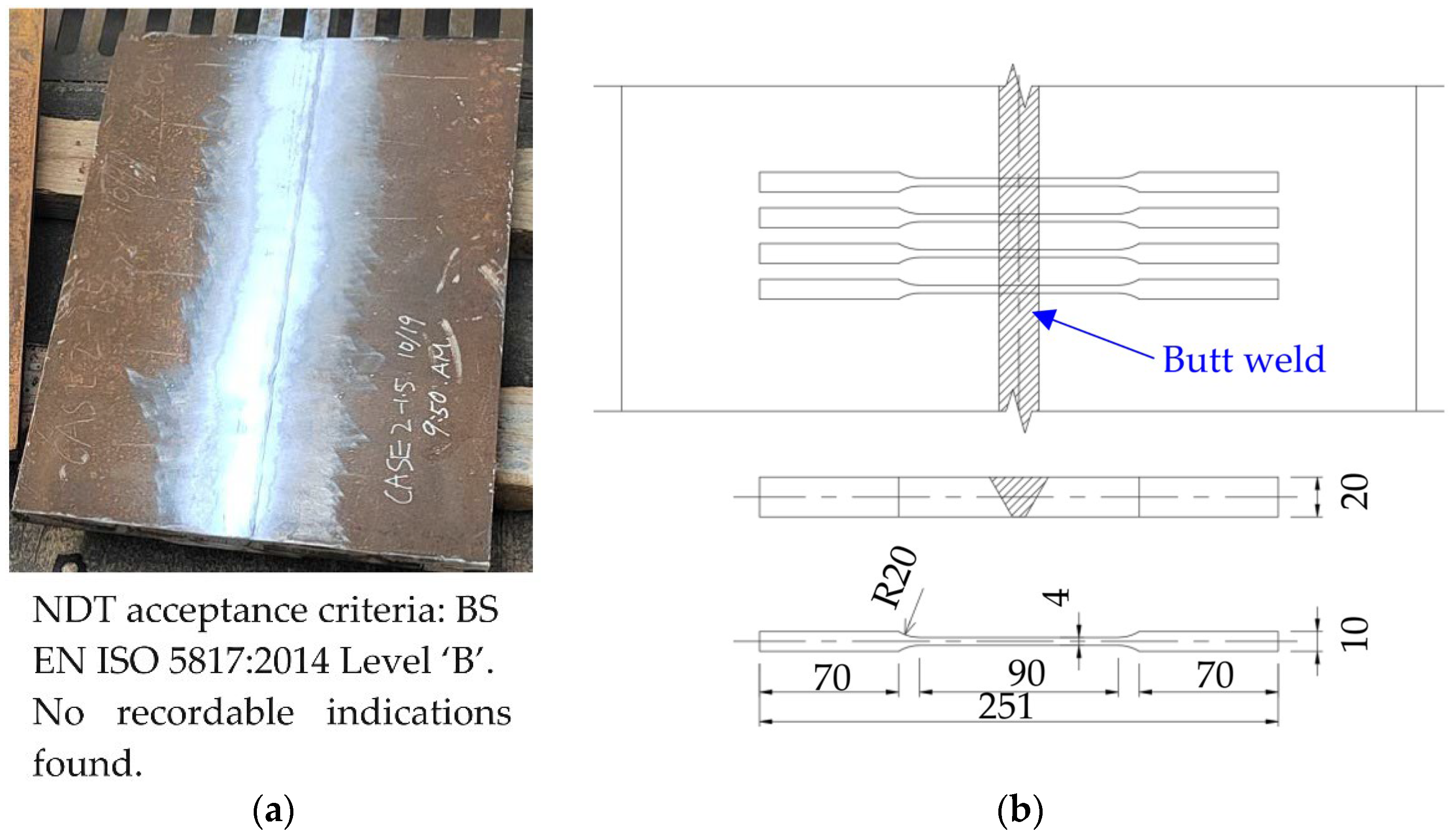
Non-destructive testing, including visual testing (VT), magnetic particle testing (MT), and ultrasonic testing (UT), was carried out in all test coupons. The inspection standards used are BS EN ISO 17637:2016 [25], BS EN ISO 17638:2016 [26], and BS EN ISO 17640:2018 [27] for VT, MT, and UT, respectively. The acceptance criteria are BS EN ISO 5817: 2014 Level ‘B’ [28]. All the welded sections passed the NDT inspection. The welded sections of Series I and Series II were processed into tensile coupons according to Figure 6 and tested in the laboratory of PolyU (see Figure 7). For the welded sections of Series III, standard welding procedure qualification tests (WPQT) were carried out in a HOKLAS LAB. The test results for tensile resistance are presented and discussed in Section 4.1.

3.2. Test Methodology for Compressive Resistances

H-section compression members are widely used for truss members, columns, and steel piles. Considering the wide variety of application scenarios, the effectiveness of on-site welding for connecting compressive H-section members was studied. The methodology for the test is outlined below.
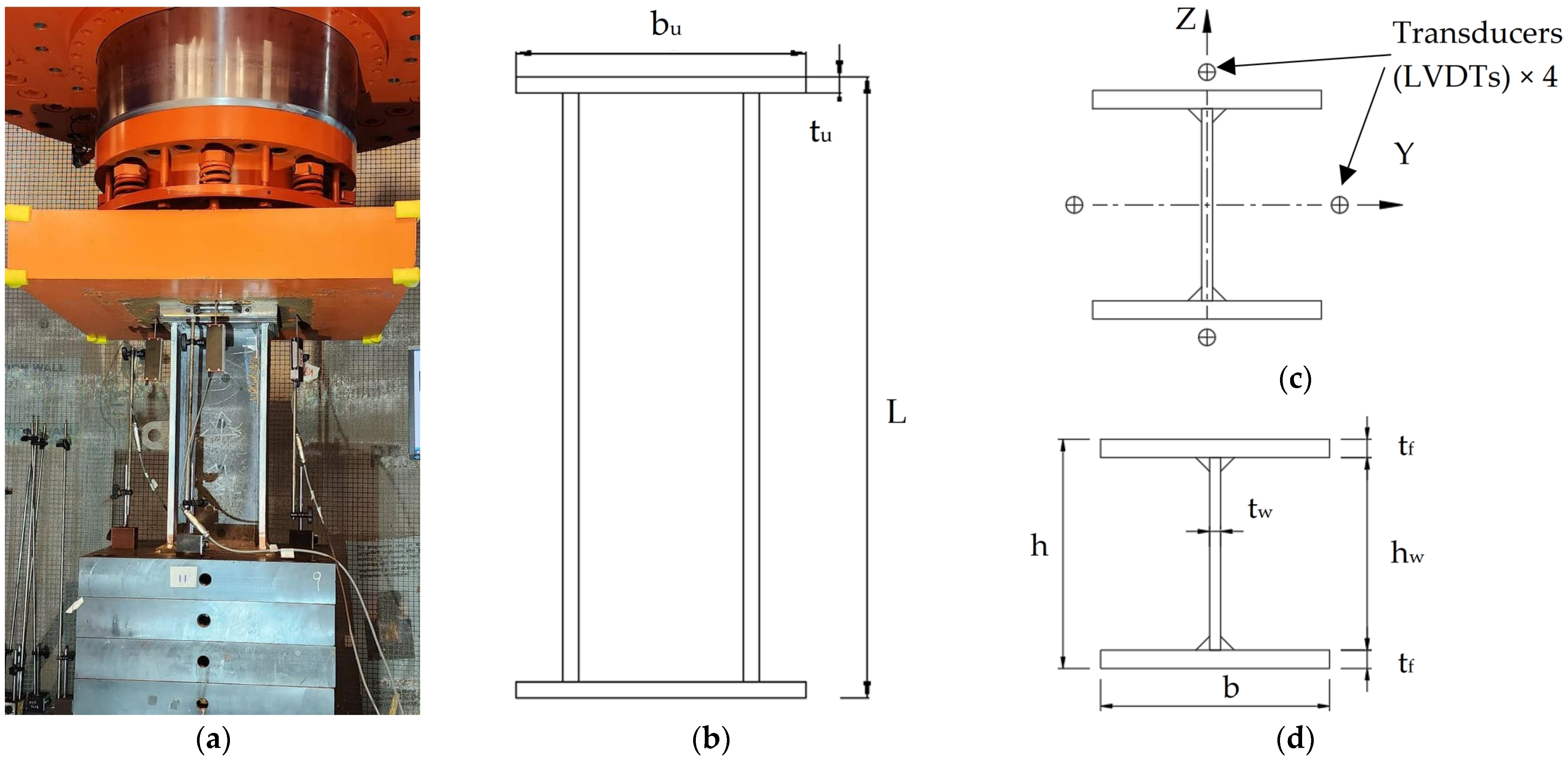
First, built-up H-section members were fabricated in the factory. Then, two members were on-site welded using FPBW to form a complete compression specimen. For the convenience of later laboratory loading, a square end plate was welded to one end of each segment during factory processing. Heat input energy values of 1.0 kJ/mm, 1.5 kJ/mm, and 2.0 kJ/mm were applied for the splicing welding of specimens C10, C15, and C20, respectively. For comparison analysis, specimen C-control with no splicing welding joint in the middle of the member length was fabricated in the factory. As shown in Figure 8, the fabrication process involves three stages:
(1)
Stage 1, the fabrication of H-sections;
(2)
Stage 2, the temporary connecting;
(3)
Stage 3, the on-site splicing of two H-sections.
Joint Detail A in Figure 3 was used in the on-site butt welding of the H-section specimens.
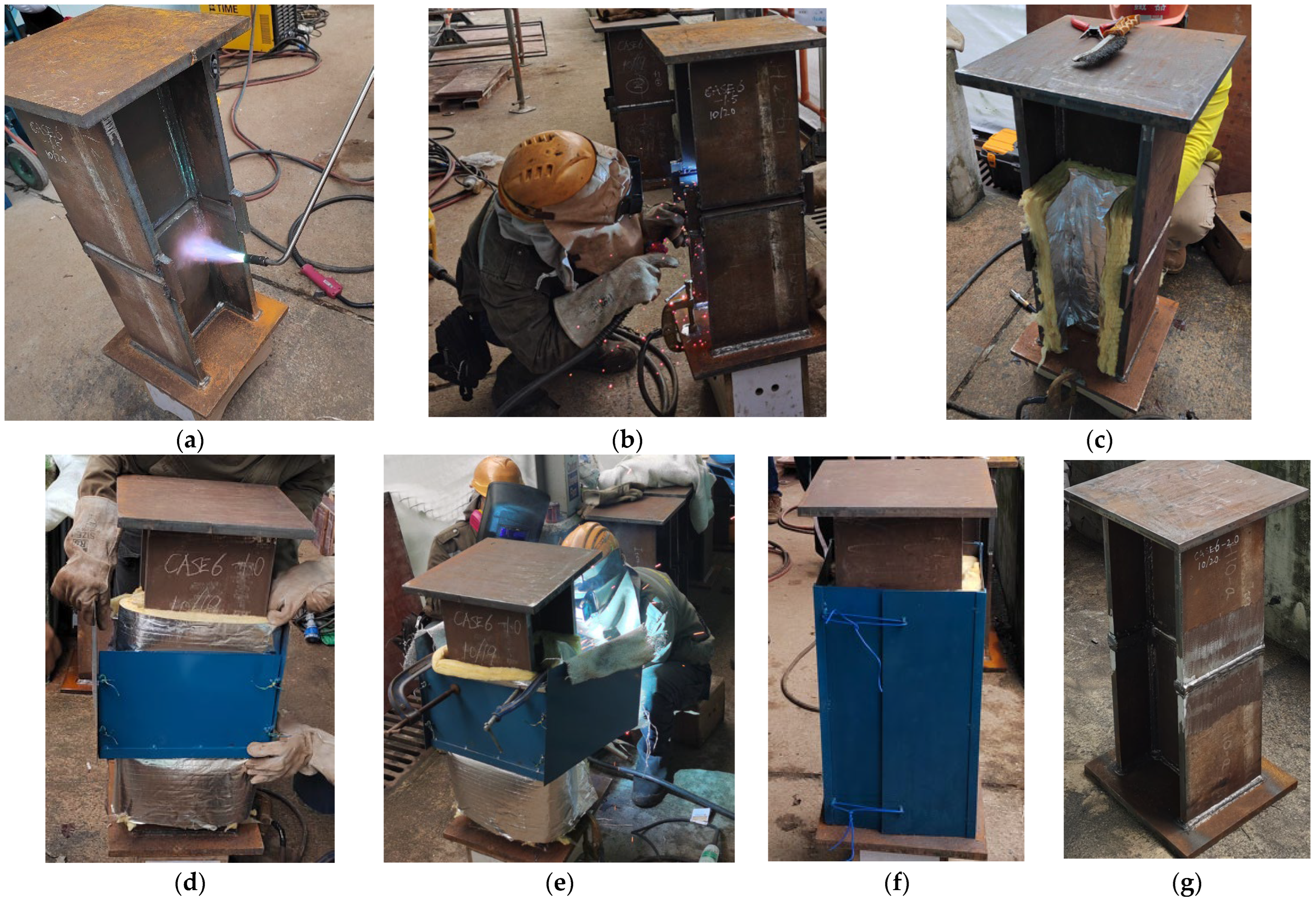
The main steps of on-site butt welding of S690 H-section specimens are listed below and briefly shown in Figure 9a–f. Insulated materials were used to wrap welded components for slow cooling, replacing the PWHT. A wind block was set up during welding to simulate actual on-site welding.
(1)
Pre-heating;
(2)
Multi-pass welding of the web plate;
(3)
Wrapping insulation material around the web plate;
(4)
Installation of windshield;
(5)
Multi-pass welding of the first flange plate;
(6)
Wrapping insulation material around the first flange plate;
(7)
Relocation of the windshield;
(8)
Multi-pass welding of the second flange plate;
(9)
Wrapping insulation material around the second flange plate.
The typical H-section specimen after non-destructive testing is shown in Figure 9g. The acceptance criteria for NDT are BS EN ISO 5817: 2014 Level ‘B’, the same as that for welded steel plates mentioned in Section 3.1. All the welded H-sections passed the NDT inspection. After the NDT inspection, the H-section specimens were tested under compression in PolyU’s laboratory. As shown in Figure 10 and Table 6, a hydraulic actuator was employed to apply compressive loads in the axial direction. The load was introduced via spherical hinges. No additional lateral restraints were applied to the test specimen. The applied loads and the corresponding deformation were measured by calibrated high-precision load cells and four calibrated LVDTs, respectively.

4. On-Site Welding Test Result

4.1. Test Results of Tensile Resistances

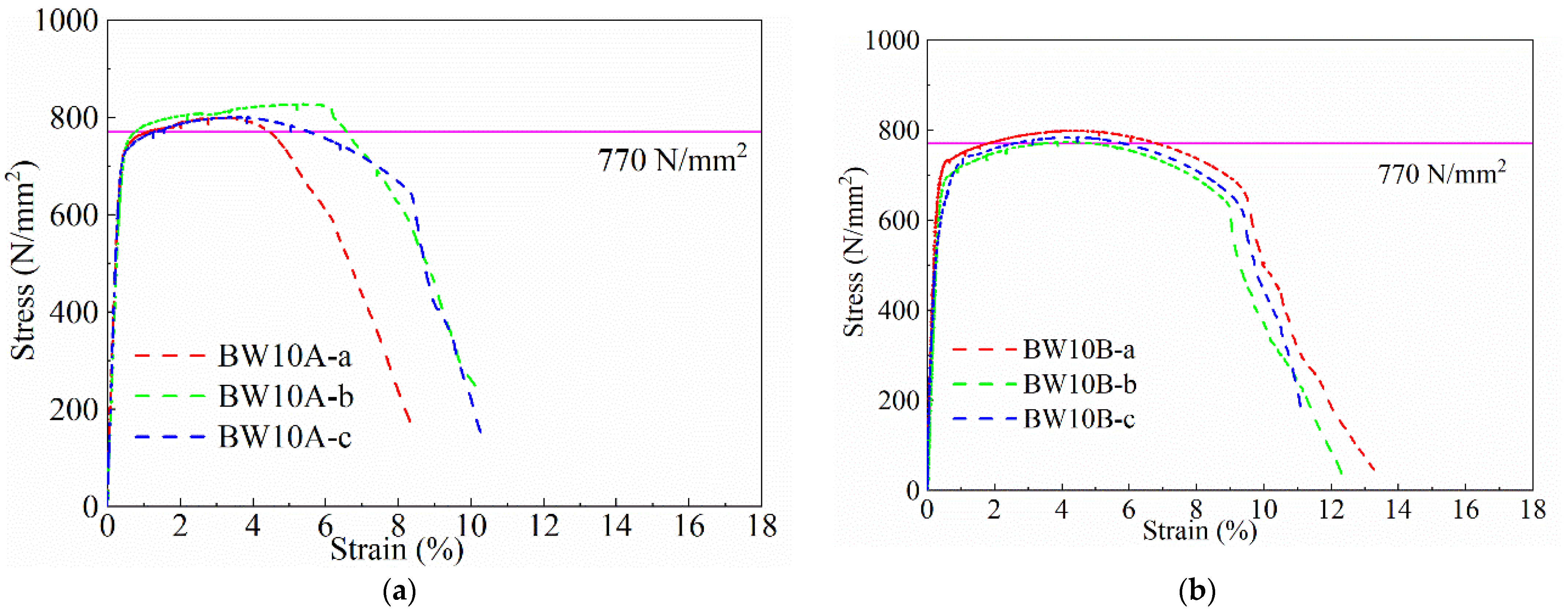
Three tensile coupons were fabricated from each welded section of Series I and II. The suffixes “-a,” “-b,” and “-c” were appended to the reference number of the welded sections to indicate the associated tensile test coupons, as illustrated in Table 7 and Table 8. For Series III, standard welding procedure qualification tests including tensile tests, Charpy impact tests, hardness tests, and bend tests were performed. The test results of welded sections are summarized in Table 7, Table 8 and Table 9. By comparing Table 7 and Table 8, it can be observed that under similar heat input energy, specimens with joint details A exhibit higher tensile strength than those with joint details B, with all values exceeding 770 MPa. Conversely, specimens with joint details B demonstrate better ductility than those with joint details A. In Table 9, for specimens using joint detail B with heat inputs of 0.72 kJ/mm, 1.11 kJ/mm, and 1.56 kJ/mm, it can be observed that higher heat input leads to lower tensile strength and impact performance. The tensile strength of all test coupons is larger than the specified value of 770 N/mm2 according to EN 10025-6:2019, indicating that the on-site welding of these joints satisfies the strength requirements. Furthermore, the test results of Series III satisfied the requirements of corresponding standards, indicating that the welding procedures used for Series III could pass the welding procedure qualification and be used in actual engineering. For the on-site welding procedures tested, it was found that:
(1)
The use of fire blankets or insulated materials for slow cooling is a viable alternative to post-weld heat treatment (PWHT) in different scenarios;
(2)
Heat input energy range of 0.7 kJ/mm–1.5 kJ/mm is practicable;
(3)
Both welding joint details A and joint details B are suitable;
(4)
The wind block device employed can effectively function to ensure that GMAW welding can be performed in the shielded area, even with an ambient wind speed of 5.5 m/s;
(5)
Based on the test results of Series III, the ultimate strength of tensile coupons decreases with increasing heat input energy, which is consistent with the former research [10].
By comparing the total time spent during the welding process, it was found that the welding efficiency of Series I is higher than that of Series II and Series III, which indicates that Joint Detail A is preferable to Joint Detail B, considering the welding efficiency.
Figure 11 presents the tensile coupons of BW10B following failure, which serves as a representative example. The results for other samples were consistent with those of BW10B. It was noted that slight necking occurred prior to fracture, and the fracture surface exhibited no significant welding defects.
Engineering stress-strain curves of Series I and Series II are plotted in Figure 12. It can be seen that the stress-strain curves of the three tensile specimens in Series I have a certain deviation in the descending stage, while the stress–strain curves of the three specimens in Series II are in good agreement. This shows that the welding quality of Series I is lower than that of Series II. That is, Joint Detail A requires a more experienced welder than Joint Detail B.

4.2. Test Results of Compressive Resistances

The compressive failure modes for the H-section members are shown in Figure 13a,b, i.e., plastic local buckling. After a thorough examination, no cracks were found in the weld zone, indicating that there was no welding failure.
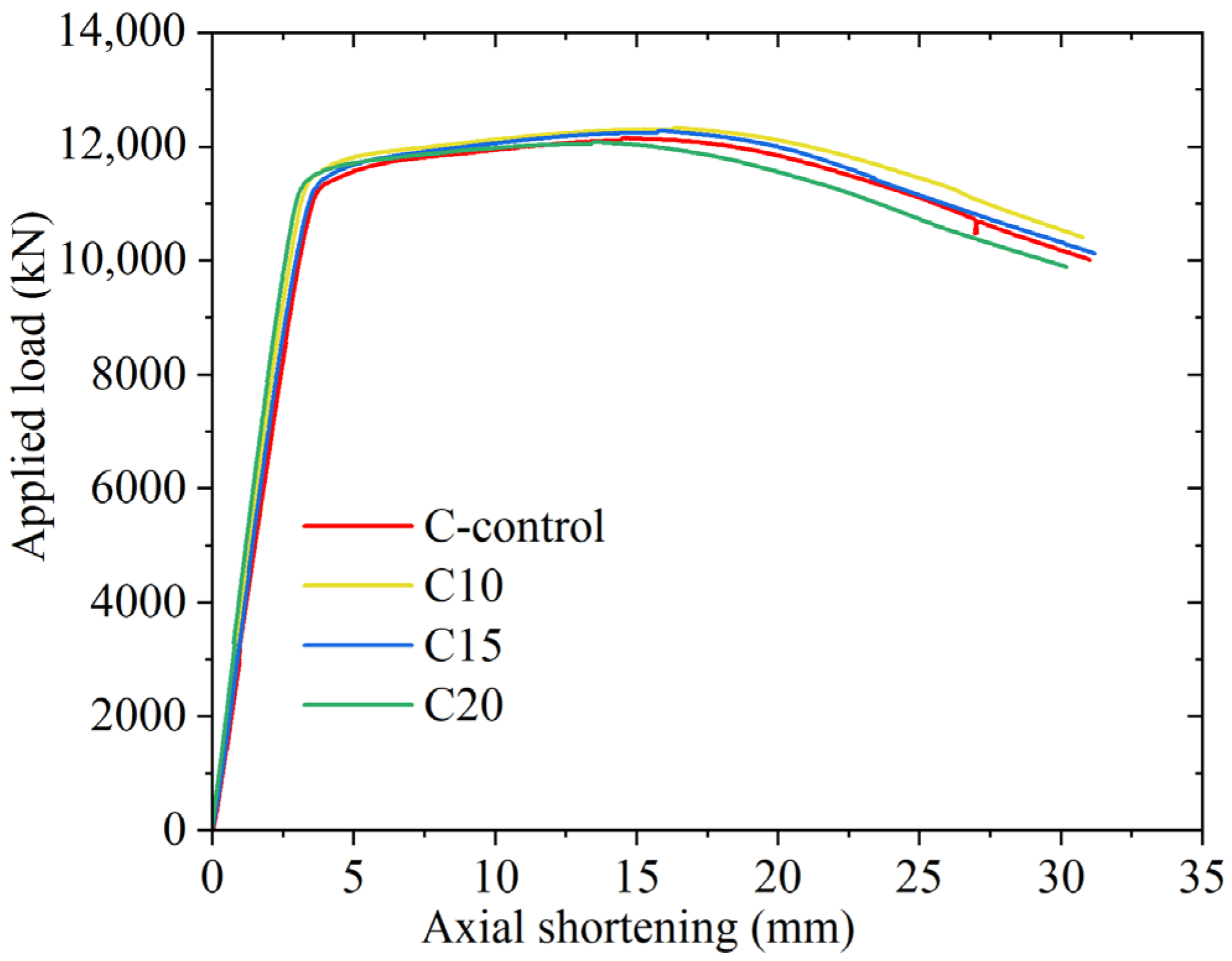
The main test results are demonstrated in Figure 14 and Table 10. As shown in Figure 14, the load–displacement curves for the splicing specimens (named as C10, C15, and C20) closely align with those of the control specimen (C-control). This indicates that the splicing weld has a minimal impact on the overall performance of the compressive specimens.
The measured resistances and design resistance are summarized in Table 10. Among these, Nc,Rty represents the measured yield resistance, which corresponds to the endpoint of the straight segment of the load-deformation curve. Nc,Rt denotes the measured ultimate resistance, corresponding to the peak point on the load-deformation curve. Nc,Rd indicates the design resistance, calculated as the product of the cross-sectional area A0 and the design strength of 690 MPa. As listed in Table 10, the estimated yield strength of spliced H-section members (i.e., C10, C15, and C20) is almost the same as that of the control specimen (C-control), with variations smaller than 4%, and all larger than 690 N/mm2. The measured ultimate resistances are 1.20 to 1.22 of their nominal design resistances. It can be concluded that:
(1)
Using insulated materials for slow cooling is a feasible alternative to PWHT;
(2)
Heat input energy range of 1.0 kJ/mm–2.0 kJ/mm is practicable for the splicing of compressive members tested, as the splicing welding showed minor influence on the compressive strength;
(3)
The wind block device used was easy to operate and convenient for on-site welding.

5. Conclusions

This research paper presents a comprehensive study on the on-site welding of high-strength S690 steel in Hong Kong, focusing on the evaluation of tensile and compressive strengths under various welding conditions and joint details. Based on the test results and analysis, several key conclusions can be drawn below:
(1)
Compliance with strength requirements:
The tensile strengths of test coupons are larger than the specified value of 770 N/mm2 according to EN 10025-6:2019. This indicates that the on-site welding procedures employed for S690 steel are capable of meeting the necessary structural strength standards.
(2)
Impact on compressive strength:
The splicing welding of H-section members showed negligible effects on yield strength, with variations remaining below 4% compared to the control specimen. This indicates that the splicing method is reliable for compressive members and does not compromise structural performance.
(3)
Optimal heat input energy range:
The study established that a heat input energy range of 0.7 kJ/mm to 1.5 kJ/mm is effective for tensile applications, while a range of 1.0 kJ/mm to 2.0 kJ/mm is suitable for splicing compressive H-section members. This flexibility allows for adaptation based on specific project requirements.
(4)
Effectiveness of joint details:
Both joint detail A and joint detail B demonstrated suitability for the welding processes. However, joint detail A was found to be more efficient, albeit necessitating a higher skill level from the welder compared to joint detail B.
(5)
Feasibility of eliminating PWHT:
The results demonstrate that the use of fire blankets or insulated materials for slow cooling is a viable alternative to post-weld heat treatment (PWHT) in different scenarios. These approaches not only simplify the welding process but also enhance efficiency on-site.
(6)
Wind block efficiency:
The implementation of a wind block device proved effective in shielding the welding area from ambient wind speeds of up to 5.5 m/s for GMAW welding. This innovation enhances the feasibility of conducting on-site welding in various weather conditions.
This study addresses the existing gap in on-site welding technology for S690 steel in Hong Kong. The findings confirm the reliability and effectiveness of the investigated on-site welding processes. The methodologies employed not only satisfy engineering requirements but also provide practical solutions for enhancing welding efficiency in diverse applications. Future research could focus on further optimizing welding procedures and exploring additional environmental influences to broaden the applicability of welding for high-strength S690 steel in various structural and environmental contexts.

Author Contributions

Conceptualization, X.Z. and J.H.; methodology, X.Z. and Y.Z.; investigation, X.Z. and J.S.; resources, J.H. and Z.Z.; writing—original draft preparation, X.Z. and Y.Z.; writing—review and editing, X.Z. and W.L.; supervision, J.H. and Z.Z.; project administration, J.S. and M.Y.; funding acquisition, Z.Z. and W.Q.; formal analysis, Z.H. and J.F. All authors have read and agreed to the published version of the manuscript.

Funding

This research was funded by China State Construction International Holdings Ltd. (CSCI-2023-Z-15).

Data Availability Statement

Data are contained within the article.

Acknowledgments

The R&D funding support for “Research on key technologies and processes for on-site welding of high-strength steel” from China State Construction International Holdings Ltd. is gratefully acknowledged. We would like to express our sincere gratitude to Kwok-Fai Chung, Ho-Cheung Ho, and Bin Li from the Hong Kong Polytechnic University for providing technical guidance and testing for this research.

Conflicts of Interest

All authors are employed by the company China State Construction Engineering (Hong Kong) Ltd. The authors declare no conflicts of interest. The authors declare that this study received funding from China State Construction International Holdings Ltd. The funders had no role in the design of the study; in the collection, analysis, or interpretation of the data; in the writing of the manuscript; or in the decision to publish the results.

References

  1. Rasmussen, K.J.; Hancock, G.J. Plate slenderness limits for high strength steel sections. J. Constr. Steel Res. 1992, 23, 73–96. [Google Scholar] [CrossRef]
  2. Rasmussen, K.J.; Hancock, G.J. Tests of high strength steel columns. J. Constr. Steel Res. 1995, 34, 27–52. [Google Scholar] [CrossRef]
  3. Coelho, A.M.G.; Bijlaard, F.S.K. Experimental behaviour of high strength steel end-plate connections. J. Constr. Steel Res. 2007, 63, 1228–1240. [Google Scholar] [CrossRef]
  4. Coelho, A.M.G.; Bijlaard, F. High strength steel in buildings and civil engineering structures: Design of connections. Adv. Struct. Eng. 2010, 13, 413–429. [Google Scholar] [CrossRef]
  5. Shi, G.; Ban, H.Y.; Bijlaard, F.S.K. Tests and numerical study of ultra-high strength steel columns with end restraints. J. Constr. Steel Res. 2012, 70, 236–247. [Google Scholar] [CrossRef]
  6. Xia, J. Flexural behavior of high-strength steel and ultra-high-performance fiber-reinforced concrete composite beams. Buildings 2024, 14, 131. [Google Scholar] [CrossRef]
  7. Li, Y.H.; Lee, C.C.; Cai, Y.C. Recent research advances in high-performance steel tubular members: Material Properties, Stub Columns, and Beams. Buildings 2023, 13, 2713. [Google Scholar] [CrossRef]
  8. Chung, K.F. Effective use of high strength S690 to S960 steel in construction. Hong Kong Eng. 2022, 50, 8–18. [Google Scholar]
  9. Liu, X.; Chung, K.F.; Ho, H.C.; Xiao, M.; Hou, Z.X.; Nethercot, D.A. Mechanical behavior of high strength S690-QT steel welded sections with various heat input energy. Eng. Struct. 2018, 175, 245–256. [Google Scholar] [CrossRef]
  10. Chung, K.F.; Ho, H.C.; Hu, Y.F.; Wang, K.; Liu, X.; Xiao, M.; Nethercot, D.A. Experimental evidence on structural adequacy of high strength S690 steel welded joints with different heat input energy. Eng. Struct. 2020, 204, 110051. [Google Scholar] [CrossRef]
  11. Sun, F.F.; Ran, M.M.; Li, G.Q.; Kanvinde, A.; Wang, Y.B.; Xiao, R.Y. Strength model for mismatched butt welded joints of high strength steel. J. Constr. Steel Res. 2018, 150, 514–527. [Google Scholar] [CrossRef]
  12. Zeng, Z.; Li, G.; Liu, S.W.; Huang, D.H.; Liu, Y.P.; Chan, S.L. Low-cycle fatigue of laser-arc hybrid welded S960 high-strength steel joints. J. Constr. Steel Res. 2026, 236, 110040. [Google Scholar] [CrossRef]
  13. Buildings Department of Hong Kong SAR Government. Code of Practice for the Structural Use of Steel 2011, 2023 ed.; Buildings Department of Hong Kong SAR Government: Hong Kong, China, 2023.
  14. Development Bureau; Chinese National Engineering Research Centre for Steel Construction (Hong Kong Branch) of The Hong Kong Polytechnic University; Department of Civil Environmental Engineering of Imperial College London, U.K. Design and construction in Hong Kong using high strength S690 steel. Hong Kong Eng. 2023, 51, 8–16. [Google Scholar]
  15. Schröter, F. Trends of using high-strength steel for heavy steel structures. In Progress in Steel, Composite and Aluminium Structures; Giejowski, M.A., Kozowski, A., lczka, L., Zióko, J., Eds.; Taylor & Francis: London, UK, 2006; pp. 292–293. [Google Scholar]
  16. Samuelsson, A.; Schröter, F. High performance steels in Europe-production processes, mechanical and chemical properties, fabrication properties. In Use and Application of High-Performance Steels (HPS) for Steel Structures; IABSE: Zurich, Switzerland, 2005. [Google Scholar]
  17. BS EN 1011-2:2001; Welding—Recommendations for Welding of Metallic Materials—Part 2: Arc Welding of Ferritic Steels. British Standards Institution: London, UK, 2001.
  18. Arsić, D.; Lazic, V.; Nikolic, R.; Aleksandrovic, S.; Marinkovic, P.; Djordjevic, M.; Rajko, Č. Application of the S690QL class steels in responsible welded structures. Mater. Eng.-Mater. Inžinierstvo 2013, 20, 174–183. [Google Scholar]
  19. Baddoo, N.; Chen, A. High Strength Steel Design and Execution Guide; Steel Construction Institute: Bracknell, UK, 2020. [Google Scholar]
  20. Nevasmaa, P. Prevention of weld metal hydrogen cracking in high-strength multipass welds. Weld. World 2004, 48, 2–18. [Google Scholar] [CrossRef]
  21. BS EN 1011-1:2009; Welding—Recommendations for Welding of Metallic Materials—Part 1: General Guidance for Arc Welding. British Standards Institution: London, UK, 2009.
  22. AWS D1.1/D1.1M:2020; Structural Welding Code-Steel. American Welding Society: Miami, FL, USA, 2020.
  23. EN 10025-6; Hot Rolled Products of Structural Steels—Part 6: Technical Delivery Conditions for Flat Products of High Yield Strength Structural Steels in the Quenched and Tempered Condition. European Committee for Standardization: Brussels, Belgium, 2019.
  24. EN ISO 16834; Welding Consumables—Wire Electrodes, Wires, Rods and Deposits for Gas Shielded Arc Welding of High Strength Steels—Classification. International Organization for Standardization: Geneva, Switzerland, 2012.
  25. BS EN ISO 17637; Non-Destructive Testing of Welds—Visual Testing of Fusion-Welded Joints. British Standards Institution: London, UK, 2016.
  26. BS EN ISO 17638; Non-Destructive Testing of Welds—Magnetic Particle Testing. British Standards Institution: London, UK, 2016.
  27. BS EN ISO 17640; Non-Destructive Testing of Welds—Ultrasonic Testing—Techniques, Testing levels, and Assessment. British Standards Institution: London, UK, 2018.
  28. BS EN ISO 5817; Welding—Fusion-Welded Joints in Steel, Nickel, Titanium and Their Alloys (Beam Welding Excluded)—Quality Levels for Imperfections. British Standards Institution: London, UK, 2014.
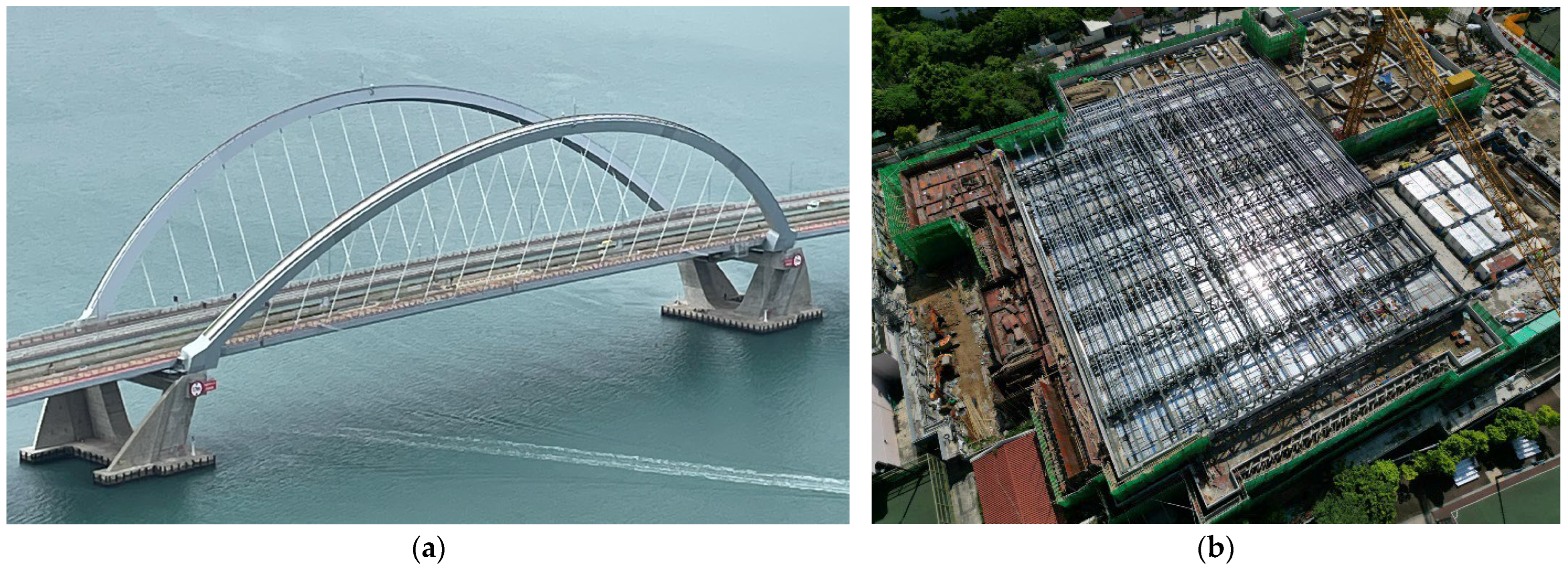
Figure 1. Two engineering cases using high-strength S690 steel in Hong Kong: (a) Steel arches of the double-arch steel bridge of the Cross-Bay Line in the Tseung Kwan O area [14]; (b) steel trusses of the Redevelopment of Kowloon Tsai Swimming Pool Complex.
Buildings 15 04102 g001
Figure 2. Preparation of welded sections (i.e., BW10A, BW10B, BW07C, BW10C, and BW15C).
Buildings 15 04102 g002
Figure 3. Joint detail.
Buildings 15 04102 g003
Figure 4. Main steps of on-site butt welding of S690 steel: (a) Pre-heating; (b) welding; (c) weld bead cleaning; (d) temperature measurement.
Buildings 15 04102 g004
Figure 5. Ventilation fan, wind block setup and wind speed measuring for BW07C: (a) Ventilation fan and wind block setup; (b) wind speed out of the wind block; (c) wind speed measurement point layout plan.
Buildings 15 04102 g005
Figure 6. Coupon extraction: (a) Typical welded section before coupon extraction; (b) dimensions of tensile coupons for butt weld joints.
Buildings 15 04102 g006
Figure 7. Tensile testing system.
Buildings 15 04102 g007
Figure 8. Fabrication and on-site welding of H-section specimens.
Buildings 15 04102 g008
Figure 9. Main steps of on-site welding of H-section specimens: (a) Pre-heating; (b) welding of the web plate; (c) wrapping insulation material after the web welding; (d) installation of windshield; (e) welding of the flange plate; (f) wrapping insulation material after welding complete; (g) typical H-section specimen after non-destructive testing.
Buildings 15 04102 g009
Figure 10. Typical configuration of the structural tests on four S690 H-sections: (a) Compression test setup; (b) elevation view; (c) transducer arrangement; (d) section dimension.
Buildings 15 04102 g010
Figure 11. Failure modes of tensile coupons BW10B-a, BW10B-b, and BW10B-c: (a) Overall view; (b) Fracture surface.
Buildings 15 04102 g011
Figure 12. Engineering stress-strain curves for Series I and Series II: (a) BW10A (for Series I); (b) BW10B (for Series II).
Buildings 15 04102 g012
Figure 13. Failure shape of the compressive specimen: (a) The control specimen; (b) typical spliced specimen.
Buildings 15 04102 g013
Figure 14. Load–axial deformation curves of S690 compression specimens.
Buildings 15 04102 g014
Table 1. Welding parameters of high-strength S690 steel and normal-strength S355 steel.
MaterialWelding ProcessHeat Input Energy
(kJ/mm)
Pre-Heat
Temperature
(°C)
Inter-Pass Temperature
(°C)
Post-Weld
Heating
S690Metal Active Gas Welding (MAGW)1.0–1.5120–130120–180230 °C hold for 1 h
S355Flux Cored Arc Welding (FCAW)1.3–2.2Not required≤300Not required
Table 2. PWHT processes recommended in some literature sources.
No.PWHT ProcessReferences
(1)150 °C, lasting for 1 h for each 10 mm of thickness[18]
(2)200 °C to 300 °C, lasting for at least 2 h[17]
(3)Around 200 °C, lasting time not mentioned[19]
(4)230 °C, lasting for 1 hWPS for welding S690 in an actual project
Table 3. Chemical compositions of materials (%).
MaterialCSiMnPSCrNiCuMo
S690 steel plate0.130.291.360.010.00140.420.030.040.038
Welding material0.0710.581.700.0090.0040.191.320.100.35
Material resources: S690 steel plate from Wuyang Iron and Steel Co. Ltd., Pingdingshan, China; welding metal, MK GHS80 from Yichang Monkey King Welding Wire Co. Ltd., Yichang, China.
Table 4. Mechanical properties of materials (from mill certificates).
MaterialYield Strength,
fy (MPa)
Tensile Strength, fu (MPa)Elongation at Fracture (%)Diffusible Hydrogen
(mL/100 g)
S690 steel plate87889814.5---
Welding material736825222.8 (using the mercury method)
Table 5. Welding program and parameters.
SeriesWelded SectionsPre-heat TemperatureInter-Pass Temperature
(°C)
q0* (kJ/mm)Voltage
U (V)
Current
I (A)
Welding Speed v (mm/s)q* (kJ/mm)Joint Detail
Series IBW10A100–130100–2501.024.02104.30.99Joint Detail A
Series IIBW10B100–130100–1651.026.22605.21.11Joint Detail B
Series IIIBW07C100–130100–1650.723.72557.10.72Joint Detail B
BW10C1.026.22605.21.11
BW15C1.526.22453.51.56
Notes: 1. q0* denotes target heat input energy, and q* denotes actual heat input energy. 2. WPS number: WPS20231012-1 for Series I, WPS20240320-1–3 for Series II and Series III. 3. Filler metal: MK GHS80 (EN ISO 16834-A-G 69 2 M Z Mn4Ni1Mo). 4. Gas composition: 80% Argon and 20% CO2. 5. Heat-input equation and example for BW10B: q* = U × I × 0.85/1000/v = 26.2 × 260 × 0.85/1000/5.2 = 1.11 kJ/mm.
Table 6. Dimensions of the Test Specimen.
DescriptionColumn Length, LEndplate Thickness, tuEndplate Width, buSection Height, hSlenderness (x Axis)
Size750 mm20 mm370 mm250 mm6.96
DescriptionSection width, bWeb thickness, twflange thickness, tfWeb height, hwEndplate flatness tolerance
Size250 mm20 mm20 mm210 mm0.3 mm
Table 7. Test results of Series I.
Welded SectionTensile SpecimenHeat Input Energy, q (kJ/mm)Tensile Strength, fu
(N/mm2)
Elongation at Fracture, εf (%)Fracture Position
BW10ABW10A-a0.997987.60WM
BW10A-b8279.37WM
BW10A-c7999.27HAZ
Average8088.75-
Table 8. Test results of Series II.
Welded SectionTensile SpecimenHeat Input Energy, q (kJ/mm)Tensile Strength, fu
(N/mm2)
Elongation at Fracture, εf (%)Fracture Position
BW10BBW10B-a1.117989.07HAZ
BW10B-b77310.16HAZ
BW10B-c7839.63HAZ
Average7859.62-
Table 9. Test results of Series III.
Welded SectionHeat Input Energy, q (kJ/mm)Tensile Strength, fu
(N/mm2)
Charpy Impact Energy at −40 °C, (J)Hardness Test
(Vickers HV10)
Bend Test
HAZWMBPHAZWM
BW07C0.72829, 839237, 182, 21492, 69, 90263–290239–299247–332No rejectable defect
Average834211 > 3083 > 30<450
BW10C1.11812, 818207, 69, 11493, 63, 86259–322230–286250–264No rejectable defect
Average815130 > 3081 > 30<450
BW15C1.56791, 78850, 39, 15166, 94, 80235–282226–264235–256No rejectable defect
Average789.580 > 3080 > 30<450
Table 10. Compression test results of S690 H-sections.
SpecimenMeasured Area, A0
(mm2)
Measured ResistanceDesign Resistance,
Nc,Rd (kN)
Estimated Yield Strength, fy,e (N/mm2)Nc,Rt/Nc,RdRatio of fy,e
Nc,Rty (kN)Nc,Rt (kN)
C-control14,55011,56412,15410,040794.81.211.000
C1014,65911,49012,33510,115783.81.220.986
C1514,70311,30312,28110,145768.81.210.967
C2014,58011,48212,08710,060787.61.200.991
Note: Design resistance, Nc,Rd = A0 × 690 N/mm2; Estimated yield strength, fy,e = Nc,Rty/A0.
Disclaimer/Publisher’s Note: The statements, opinions and data contained in all publications are solely those of the individual author(s) and contributor(s) and not of MDPI and/or the editor(s). MDPI and/or the editor(s) disclaim responsibility for any injury to people or property resulting from any ideas, methods, instructions or products referred to in the content.