Article

Numerical Study on the Impact Resistance Performance of RC Walls Protected by Honeycomb Sandwich Panels

1
School of Intelligent Manufacturing, Qingdao Huanghai University, Qingdao 266427, China
2
School of Smart City Engineering, Qingdao Huanghai University, Qingdao 266427, China
3
Jiangxi Flight University, Nanchang 330088, China
4
School of Civil Engineering, Qilu Institute of Technology, Jinan 250200, China
5
School of Civil Engineering, Qingdao University of Technology, Qingdao 266520, China
*
Author to whom correspondence should be addressed.
Buildings 2025, 15(21), 3921; https://doi.org/10.3390/buildings15213921
Submission received: 17 September 2025 / Revised: 23 October 2025 / Accepted: 28 October 2025 / Published: 30 October 2025
(This article belongs to the Section Building Structures)

Abstract

Reinforced concrete walls (RC walls) are widely used in transportation, building structures, and civil air defence engineering. RC walls are vulnerable to low-velocity impact, such as the fall of components caused by earthquakes or explosions, for example, and the impact from road objects, such as vehicles, during their service life. When subjected to instantaneous high-energy impact, RC walls at key positions are prone to severe damage, which can further lead to structural collapse. Therefore, it is necessary to consider improving the impact resistance of key RC walls in a structure. Using a porous honeycomb structure with excellent energy absorption performance to provide impact protection for key RC walls is an effective way to reduce the damage of RC walls and thereby enhance the impact resistance of a structure. Therefore, based on the author’s previous series of experimental and numerical studies on the impact resistance of RC walls, as well as the high-mass pendulum impact experimental study on the honeycomb sandwich panel composite RC wall (HSP-RC wall), this paper adopts a multi-scale modelling method in micro-mechanics and macro-mechanics to establish a pendulum impact finite element model (FEM) for the HSP-RC wall. The representative volume element (RVE) and periodic boundary condition (PBC) are used to calculate the elastic property parameters of the honeycomb, which guide the establishment of the FEMs for the HSP-RC wall. The FEMs can avoid the computational difficulty caused by refined simulation, analyse the impact damage of the HSP-RC walls more accurately, quantify the impact protection effect of the honeycomb sandwich panel, and thus facilitate the parametric analysis of the impact resistance of HSP-RC walls with different honeycomb panel structural parameters in subsequent studies.

1. Introduction

Reinforced concrete walls (RC walls) are widely used in civil air defence, transportation, and nuclear island engineering fields. These projects are in complex environments and may be threatened by high-mass, low-velocity impact loads, such as vehicles and falling rocks. Therefore, the impact resistance performance and effective protection methods of key RC walls in various fields hold research significance. However, current research on the out-of-plane, high-mass, low-velocity collision of RC walls is relatively limited, and there is an urgent need for targeted protection of key RC walls to enhance their impact resistance performance.
To improve the impact resistance of RC walls, scholars have conducted some re-search on the use of carbon fibre, aramid fibre, and other reinforcement methods, as well as measures such as spraying polyurea and other elastomers [1]. Both of these methods can effectively improve the impact resistance of RC walls, reduce the impact acceleration and stress peak, and decrease the impact damage of RC walls. There is little research on the impact resistance and protection measures of RC walls. Due to the larger size of the RC wall surface and the smaller width of the beam surface, the research on impact protection of RC walls can also refer to the research on impact protection of RC slabs.
The study of the impact resistance performance of RC slabs mainly relies on two methods: experiments and numerical simulation. The experiments include the drop hammer test, pendulum test, etc. Although experimental research is intuitive and reliable, capturing dynamic responses under extreme conditions is costly, complex, and sometimes challenging. Therefore, numerical simulation techniques have been widely applied. Researchers simulate the impact process by establishing detailed finite element models (FEMs), including concrete, steel bars, reinforcement materials, and impactors, then introducing material constitutive models that consider strain rate effects (such as the KCC model for concrete and the Cowper–Symonds model for steel). After experimental verification, these FEMs can be effectively used for parametric analysis and structural impact dynamic response prediction.
In addition to measures such as improving concrete strength [2,3], changing reinforcement materials [4,5], and altering rebar arrangement and reinforcement ratio [6,7,8], current research on enhancing the impact resistance of RC slabs mainly focuses on external bonding reinforcement materials such as CFRP [9], GFRP [4], steel plates, polyurea [10,11], and reinforcing mesh protective layers [12] to enhance their performance. Among them, CFRP is one of the most essential reinforcement materials studied. Research [13] has shown that CFRP reinforcement can significantly improve the ballistic ultimate velocity (by 9.4% to 18%) and penetration resistance of RC slabs, reduce the range of front peeling and back collapse, and effectively suppress the scattering of concrete fragments. CFRP reinforcement mainly enhances the structure’s overall integrity, delaying the propagation of cracks and structural failure. Polyurea-coated concrete exhibits a significant strain rate effect. When polyurea is coated on the end face of the concrete specimen, the peak strain increases significantly, and the brittleness improves.
Honeycomb, a thoroughly researched and processed energy-absorbing material, has excellent properties under impact loads [14,15,16]. Honeycomb can absorb energy through plastic deformation, thereby controlling the damage range and reducing the impact energy transfer during an accident. Therefore, the local deformation characteristics of honeycomb composite structures under impact loads can be applied to control the damage range and provide safety protection in civil structures. The earliest applications of classic honeycomb aluminium as an energy-absorbing device and protective material are mostly in aerospace [17,18], vehicles, submarine and ship shock wave protection, etc. Research has shown that improving the honeycomb structure [19,20], matrix [21,22], honeycomb pore cross-section, etc., can enhance its energy absorption efficiency and impact protection capability. For example, Mohammadiha and Beheshti et al. [19] conducted optimisation analysis on collision avoidance boxes using functional hierarchical honeycomb. Collision avoidance boxes are widely used in the transportation industry between the chassis and bumper of vehicles to reduce the transmission of impact energy to other parts of the car in collision accidents and ensure the safety of different front parts. Galehdari and Khodarahmi [20] used a hierarchical honeycomb structure as an aircraft seat shock absorber to absorb energy, avoid passenger injuries caused by emergency collisions, and reduce the harm to passengers in accidents.
In civil engineering, the primary use of honeycomb aluminium is not for the impact protection of buildings. The application scenarios of honeycomb sandwich panels alone include being used as exterior walls of buildings, etc. Since 2020, the construction industry’s application of honeycomb beam structures, honeycomb steel beam structures, honeycomb sandwich floor systems, wall panels, and other honeycomb structures has received widespread attention. Generally, honeycomb structures are mainly applied to form composite structural beams with honeycomb and reinforced concrete, while there is little research on the impact of adding honeycomb aluminium as an energy absorption device on the protection of structures.
However, in the research on the impact protection of RC structures, some cover layer materials are consistent with the energy absorption principle of honeycomb sandwich panels. Jin Pan et al. [21,22] designed a new U-shaped steel plate composite energy-absorbing device filled with GFRP honeycomb for bridge piers. The energy absorption characteristics of the honeycomb structure were applied to protect the bridge piers under low-speed impact. The protective effect of the honeycomb energy-absorbing device was analysed through experiments and finite element methods, which showed that the protective effect for bridge piers was good. In addition to the mass and velocity of the impact load, the stiffness and contact area of the impact body were important parameters affecting energy absorption. Xu et al. [23] studied the impact resistance and dynamic response of square regular-strength concrete (R–NSC) and ultra-high-performance concrete (R–UHPC) under the protection of closed-cell foam aluminium using a drop weight test and finite element model. They compared them with columns without a closed-cell foam aluminium protective layer (CCAF). The research results indicate that the CCAF layer can reduce impact force and absorb much impact energy, effectively protecting R-NSC and R-UHPC columns. After the foam aluminium layer is used to protect the RC column, the impact force between the column and the impactor decreases, preventing the rebound and secondary impact phenomenon after the drop hammer impacts the RC column, reducing the deflection of the RC column and effectively improving the safety. Similarly, R-UHPC columns exhibit better impact resistance than R-NSC columns, especially those with CCAF layers, showing the best impact resistance. The author also predicted the dynamic behaviour of foam aluminium in R-NSC and R-UHPC specimens through the finite element model and studied the energy absorption of each part. Song et al. [24] designed a Metal Hollow Sphere Structure (MHSS) as an energy-absorbing device for bridge piers to provide impact protection under impact loads. Through finite element modelling research, it was found that MHSS can effectively protect bridge piers under vehicle impact.
The above impact protection research can verify that honeycomb and other porous materials control the damage range and impact energy transfer during accident impacts through energy absorption. The local deformation characteristics of honeycomb under impact loads can be applied to civil structures for damage range control and safety protection. Based on the advantages of honeycomb sandwich structures and the author’s previous research on the impact resistance of RC walls [25], as well as the pendulum impact experiments of RC walls under the protection of honeycomb sandwich structures [26], this paper establishes a finite element model of pendulum impact on HSP-RC walls to study the dynamic behaviour and impact damage of HSP-RC walls, characterise the impact protection performance of honeycomb sandwich panels on RC walls, quantify their protection effect, and lay the foundation for further analysis of the influence of various structural parameters on the impact protection performance of honeycomb sandwich panels in the future.
2. FEM of HSP-RC Wall Under Impact

This section establishes the corresponding FEM based on the pendulum impact experiment of the HSP-RC wall [26]. It introduces the establishment process and specific methods of the FEM.

2.1. Geometric Modelling of Specimens

The HSP-RC wall comprises a foundation RC wall and a honeycomb sandwich panel. The geometry and dimensions of each part of the HSP-RC wall are described below.

2.1.1. Honeycomb Sandwich Panel

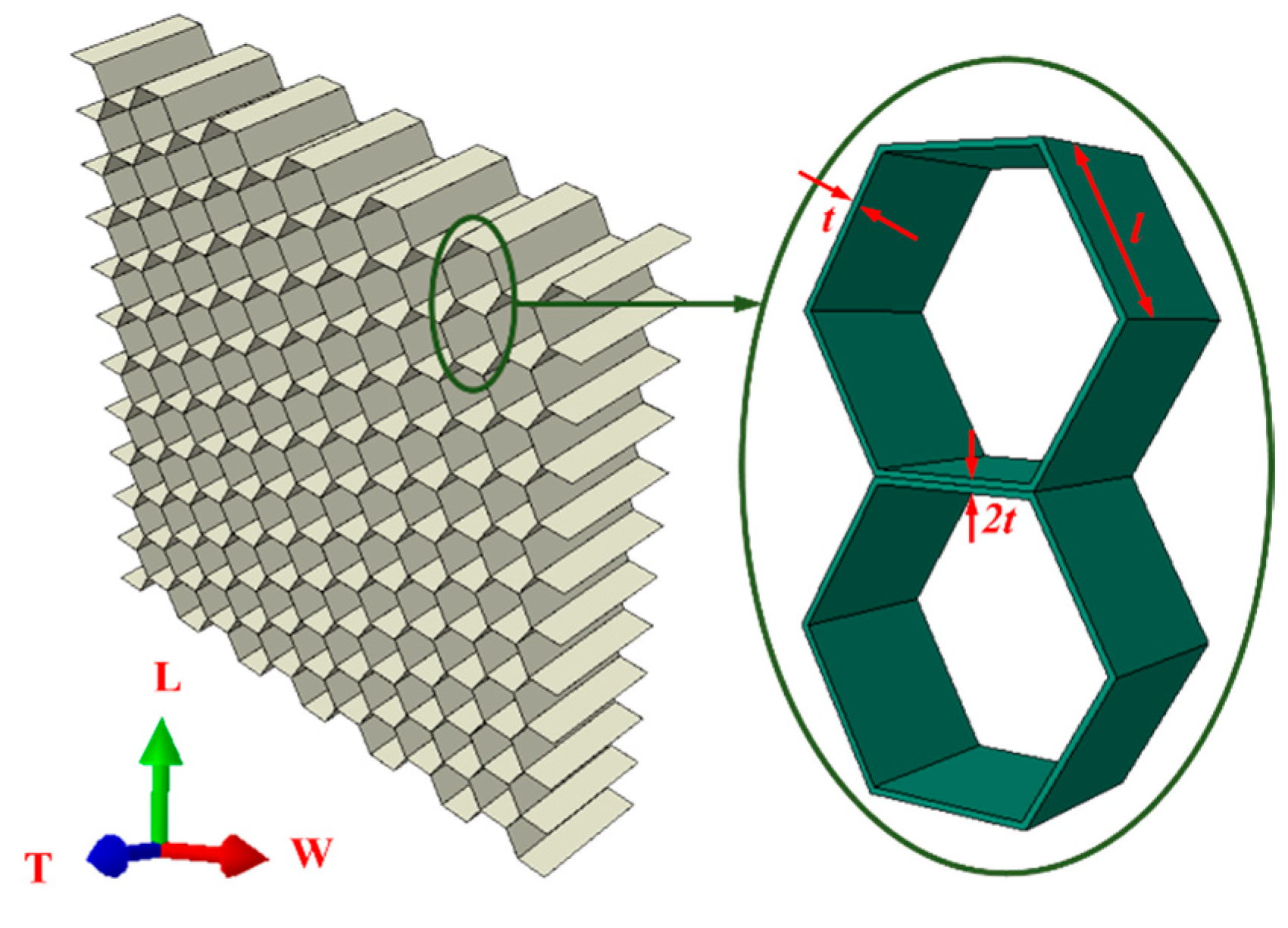
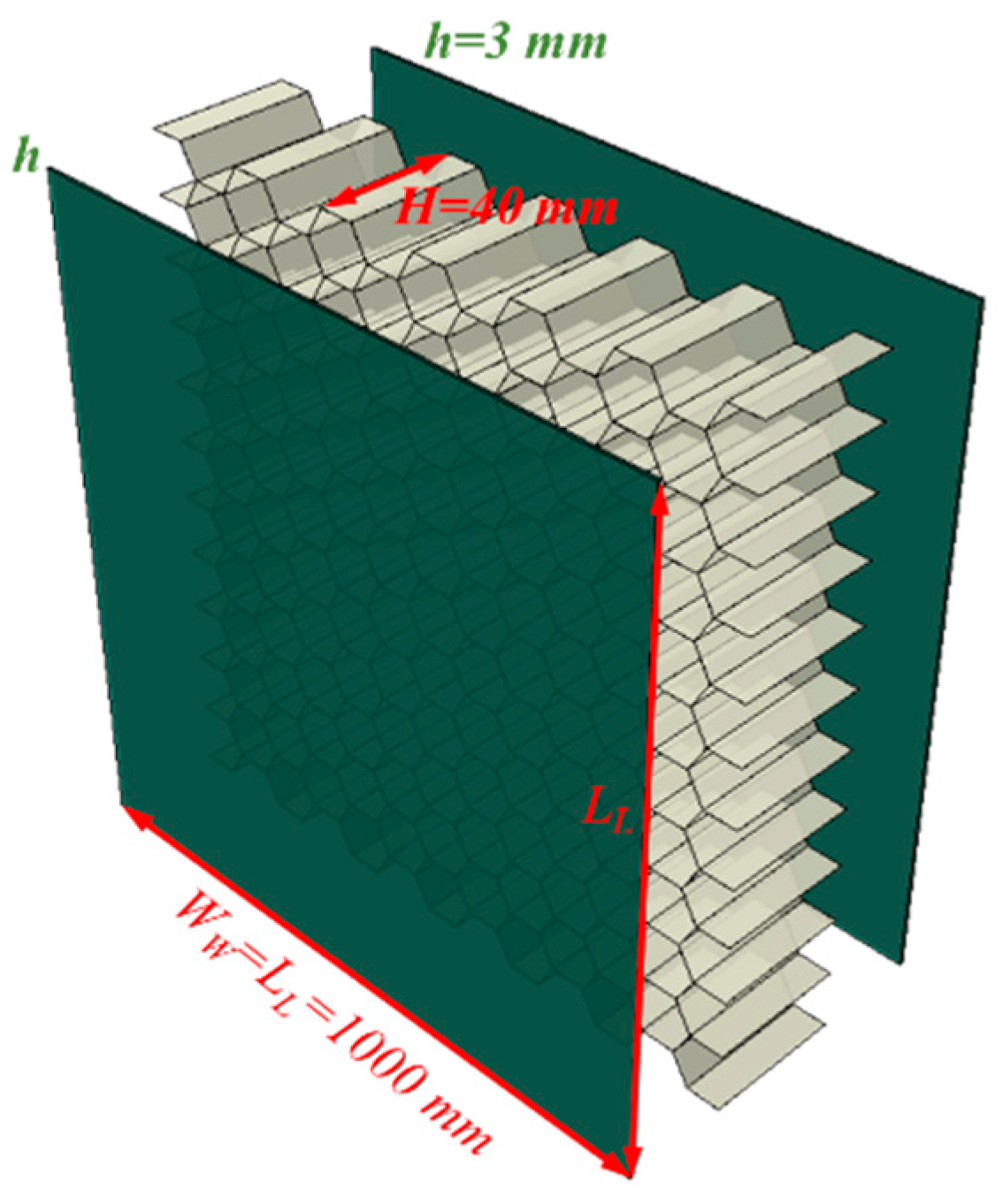
According to the pendulum impact test of the HSP-RC wall [26], ABAQUS (6.14, SIMULIA, Providence, RI, USA) FEMs consistent with the specimens and load in the experiments were established; the honeycomb core is a classic hexagonal aluminium-based honeycomb structure in the HSP-RC wall, which has three orthogonal directions: the two in-plane directions (L and W) and the out-of-plane direction (T), as shown in Figure 1.
The side length of the honeycomb cell is recorded as l, the thickness of the honeycomb cell wall is t, while the thickness of the honeycomb cell wall parallel to the direction W is 2t, H represents the thickness of the honeycomb core layer in the specimen, and h represents the thickness of the aluminium plate surface layer of the panel. The macroscopic size of the honeycomb sandwich panels used in the FEM is the same in all HSP-RC walls, as shown in Figure 2, while the l is different (l is 1 mm, 1.5 mm, 2 mm, 2.5 mm, and 3 mm, respectively), and the honeycomb cell wall thickness t is 0.04 mm.

2.1.2. HSP-RC Wall

The reinforcement protective layer thickness of the RC wall is 20 mm, the diameter of longitudinal distribution rebars is 8 mm, and the reinforcement and the detailed dimensions of HSP-RC walls in FEM are shown in Figure 3.

2.2. Material Models

The RC wall is modelled by rebar and concrete, respectively, with assigned material properties and an interaction set. The honeycomb sandwich panel is divided into an aluminium panel and a honeycomb core in FEM.

2.2.1. Concrete and Reinforcement

(1)
Concrete
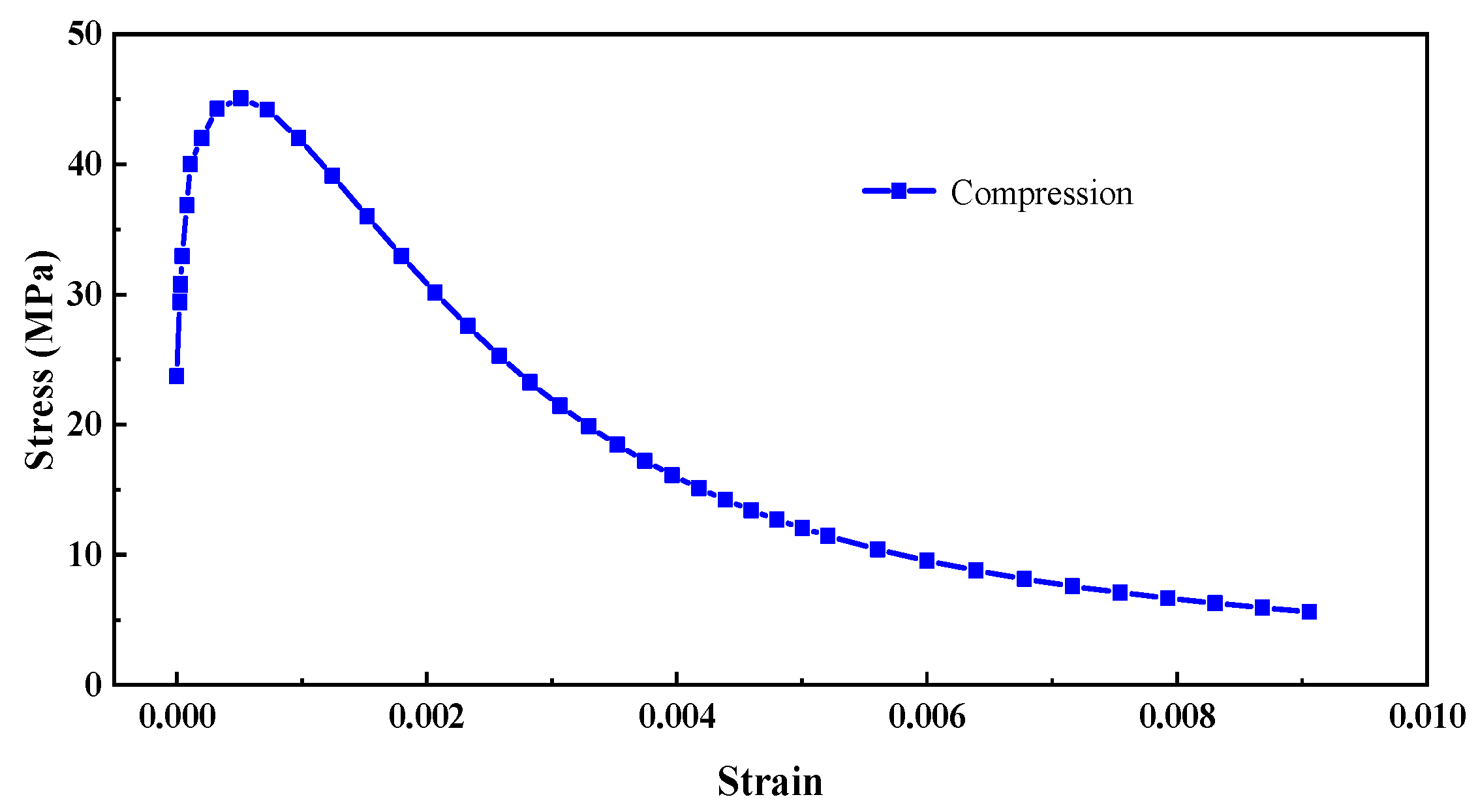
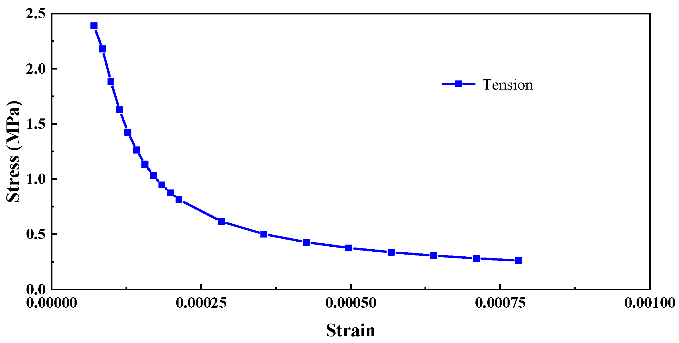
The compressive strength of concrete fc0 is 42.24 MPa, while the tensile strength ft0 is 2.39 MPa, the density is 2.45 g/cm3, Young’s modulus is 33.6 GPa, and the Poisson ratio is 0.2; the stress–strain curve of concrete input in the FEM is shown in Figure 4.
In the FEM, the Concrete Damaged Plasticity (CDP) model is adopted, and the parameters of the CDP model [25] are shown in Table 1. The meanings and calculation methods of each parameter in the CDP model refer to the article in [27].
(2)
Rebar
The rebars used in the RC wall are HRB400 hot-rolled ribbed steel bars with diameters of 6 mm, 8 mm, 20 mm, 22 mm, and 25 mm, respectively. Their yield strength fy and ultimate strength fu are shown in Table 2. The FEM characterises the constitutive relationship of rebars using a three-stage model.

2.2.2. Material Model of Honeycomb Sandwich Panel

Honeycomb sandwich panels bond honeycomb aluminium and aluminium plates on both sides. Table 3 shows the plate’s property parameters of the top layer of the composite board.
The wall thickness t of the honeycomb cells used in the experiment is 0.04 mm, while the side length l of the honeycomb cells is between 1 mm and 3 mm. However, the sandwich panel used in the wall is 1 m, and the RC wall exceeds 2 m. In the FEM, the macroscopic size of the honeycomb panel and RC wall (in the order of m) is much larger than the honeycomb cell size (in the order of 10−2 mm), which will cause significant inconvenience for calculation and modelling. Therefore, referring to the representative volume element (RVE) and periodic boundary condition (PBC) theory in the micro-mechanics of composite materials. We draw on the method of composite materials, which determines the macroscopic properties of materials based on their microscopic/mesoscopic structures and constituent properties. An RVE much larger than the characteristic size of the honeycomb structure is selected, and the RVE scale is guaranteed to have both macroscopic and microscopic duality. That is, a numerical research method is used to describe the macroscopic equivalent mechanical properties of the material by calculating the average mechanical parameters obtained from the refined modelling of the RVE. The sophisticated modelling of honeycomb is transformed into macroscopic modelling.
The material performance parameters of the honeycomb material matrix aluminium foil used in the experiment are shown in Table 4.
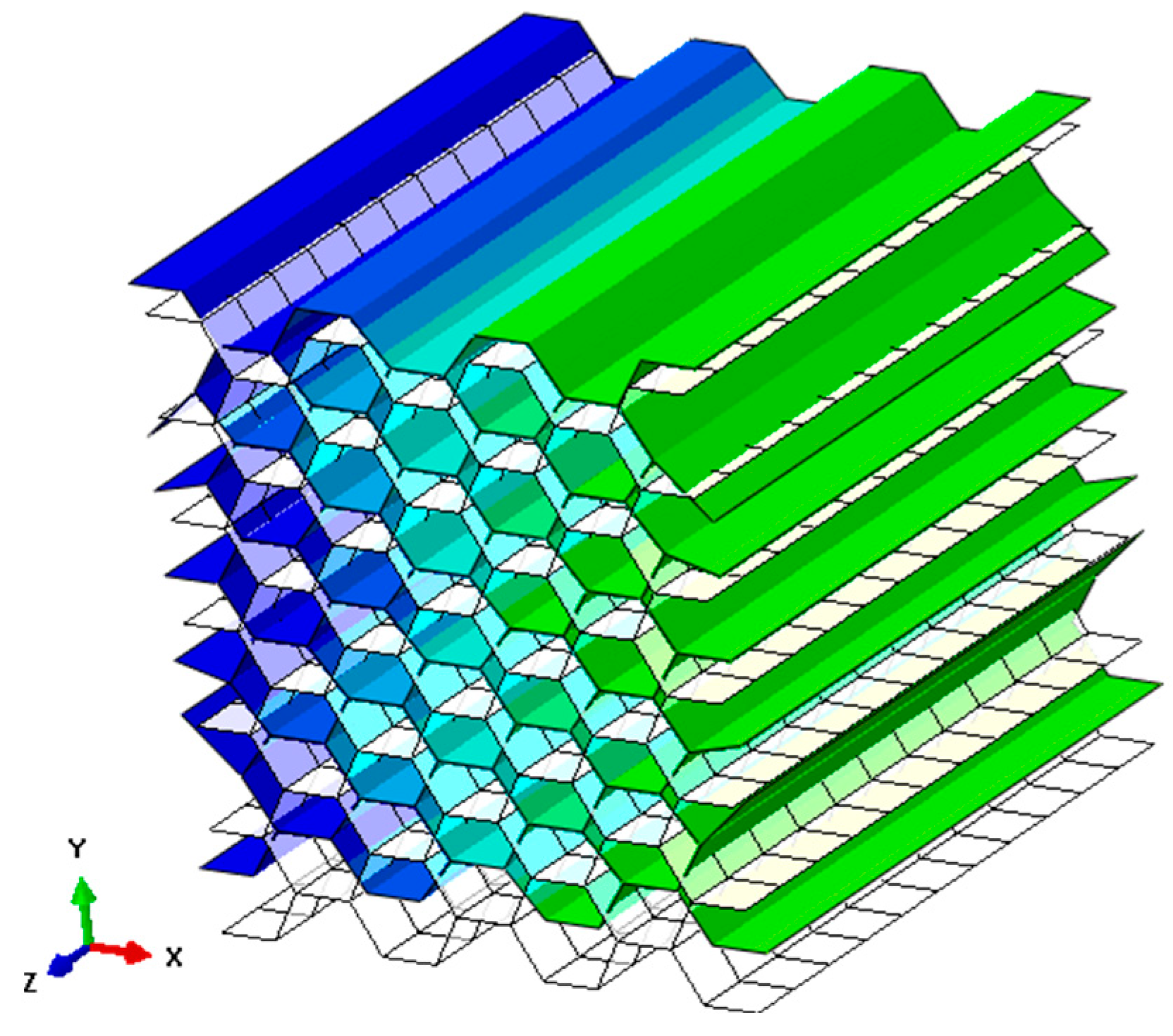
Referring to the plugin in the article in [28], the honeycomb uses RVE to calculate the equivalent elastic modulus. The ideal honeycomb material satisfies the assumptions of macroscopic distribution uniformity and microscopic cell periodicity. Referring to previous research on the mechanical properties of honeycomb aluminium, a refined geometric cube of honeycomb aluminium containing at least ten honeycomb cells is selected as an RVE. ABAQUS was used to model the honeycomb aluminium RVE. Shell elements were used for each honeycomb cell wall, and the material properties were assigned as shown in Table 4. Periodic boundary conditions (PBC) were added to the RVE, and nine engineering elastic constants of the honeycomb aluminium RVE were sequentially calculated by the equivalent model. For example, the RVE deformation and strain after calculating E22 are shown in Figure 5.
Taking honeycomb aluminium with a wall thickness t of 0.04 mm and a side length l of 2 mm as an example, the equivalent elastic modulus results obtained in the RVE equivalent material parameter calculation are shown in Table 5. E11, E22, and E33 are Young’s modulus in the X, Y, and Z directions; G12, G13, and G23 are the shear modulus in the XY, XZ, and YZ directions.
The compressive strength of honeycomb aluminium under dynamic compression can be calculated based on the compressive strength of honeycomb aluminium obtained by Harrigan et al. [29] in Equation (1).
σ c r D = σ c r + ρ 0 V i m p 2 ε 1
In the formula, σcr is the compressive strength under quasi-static compressive load; ρ0 is the initial density of the honeycomb sample; Vimp is the impact velocity; and ε1 is the strain of the honeycomb aluminium during densification.
The dynamic yield strength of honeycomb aluminium under out-of-plane impact is calculated by the out-of-plane compressive strength and macroscopic yield strength criteria under dynamic pure compression load obtained by Hong et al. [30] based on dynamic impact tests, as shown in Equation (2).
σ 2 + A d V i m p cos 2 β + B d V i m p sin 2 β τ 2 = σ c r d V i m p 2
In Equation (2), the material constant A d V i m p and B d V i m p are functions of V i m p , and its values refer to Figure 6; σ c r d V i m p can be expressed as a function of impact velocity.

2.3. Impact Load and Constraints in FEMs

2.3.1. FEMs’ Number and Impact Load

The HSP-RC wall pendulum impact FEMs consist of six RC wall specimens. Number all FEMs and apply corresponding loads. Their numbers, honeycomb sandwich panel parameters, and loads are summarised in Table 6; “RC-1” is an original RC wall, and the other five are HSP-RC walls. m, v, and Ek are impact mass, velocities and energy, respectively.

2.3.2. Velocity and Constraints

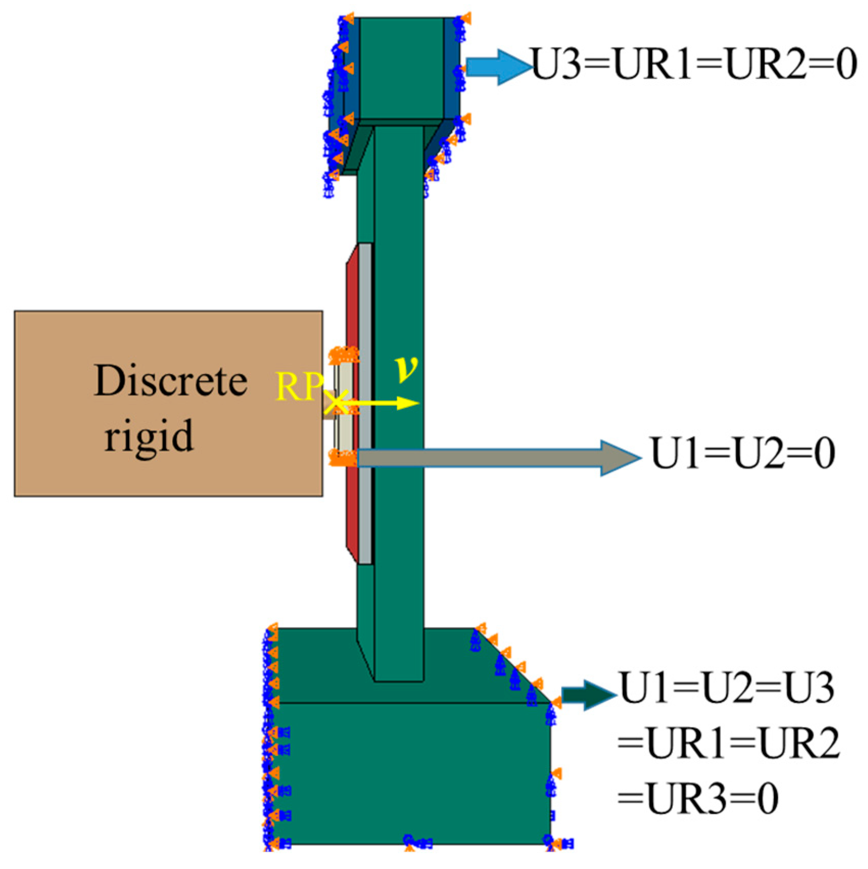
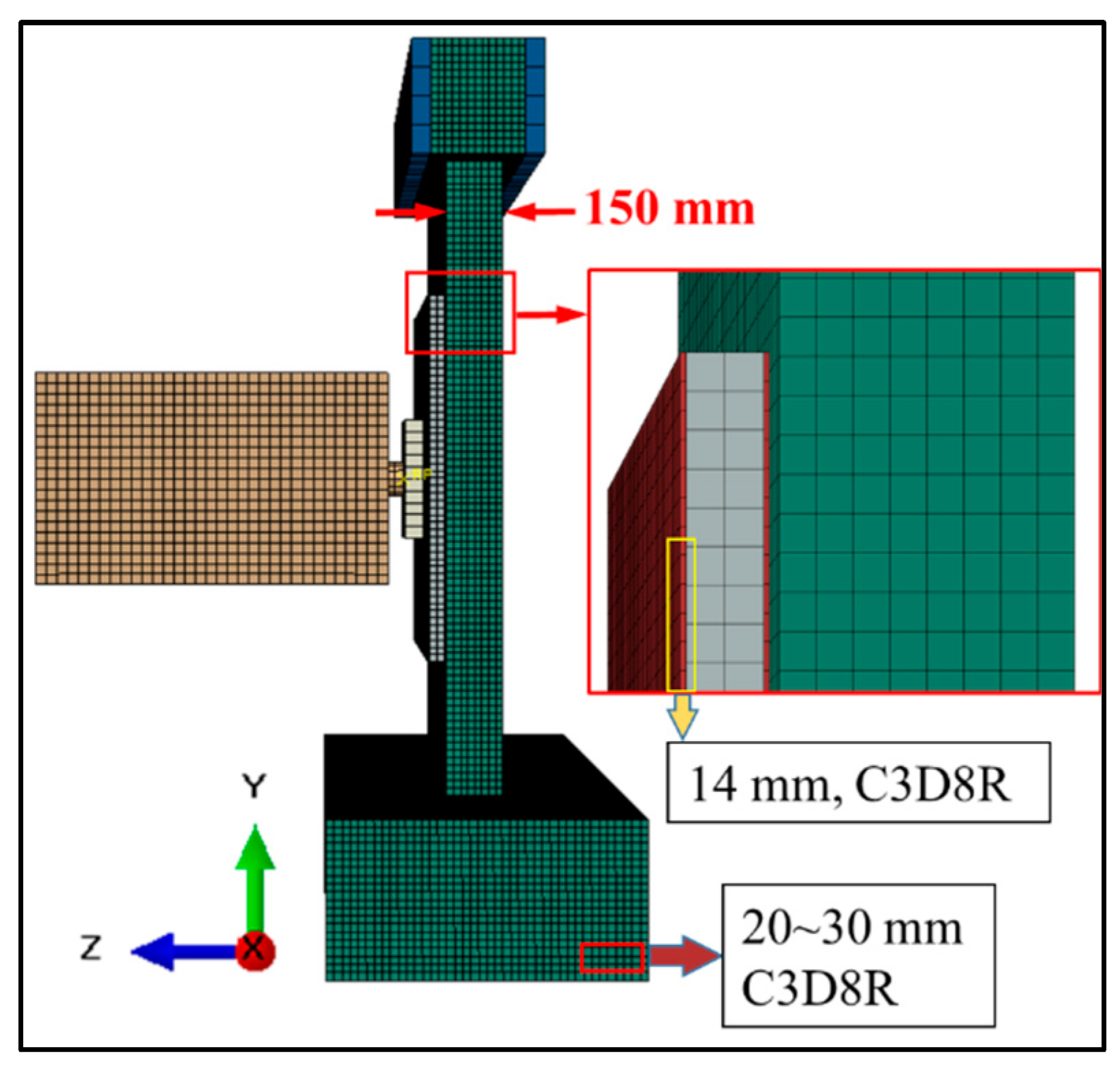
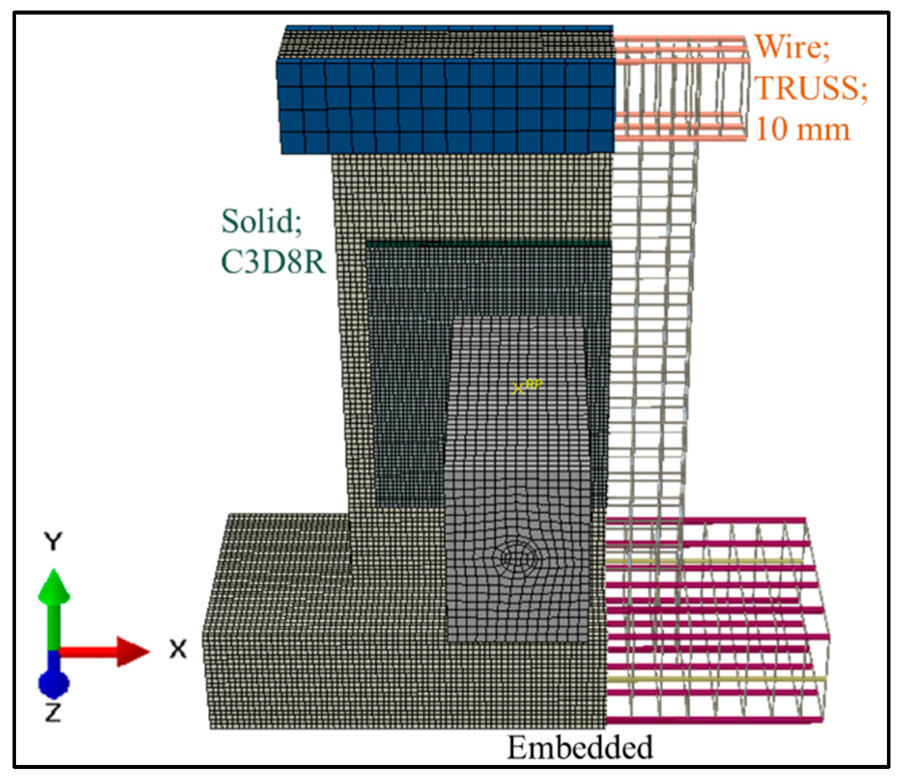
The FEM assembly and constraints of the pendulum impact on the HSP-RC wall are shown in Figure 7 and Figure 8. The pendulum’s impact speed is loaded using Predefined Field. The pendulum is set as a discrete rigid body, with the reference point for it being the RP point shown in Figure 8.

2.3.3. Contact and Mesh

Using “surface-to-surface contact” to simulate the interaction between the hammerhead of the pendulum and the iron plate [31,32,33], output the contact force between these contact surfaces and compare it with the impact force measured in the pendulum test. The rebars in FEM are beam elements of TRUSS type, with a length of 10 mm; the rest are solid elements of element type C3D8R. A convergence study was conducted to ensure that the finite element results were independent of the mesh size. After boundary condition verification and mesh convergence study, the approximate dimensions in the final FEM of these solid elements are shown in Figure 9. The tie constraint is used for the constraints between the honeycomb core layer and the surface panel, as well as between the honeycomb panel and the RC wall. Assuming a complete bond between the steel bars and concrete [34,35], and that no sliding occurs, the rebar elements are embedded into the concrete elements, as shown in Figure 10.

3. Experimental and Numerical Results

This section mainly compares the calculation results output from FEMs with the data collected from pendulum experiments.

3.1. Impact Force and Mid-Span Displacement of RC Wall

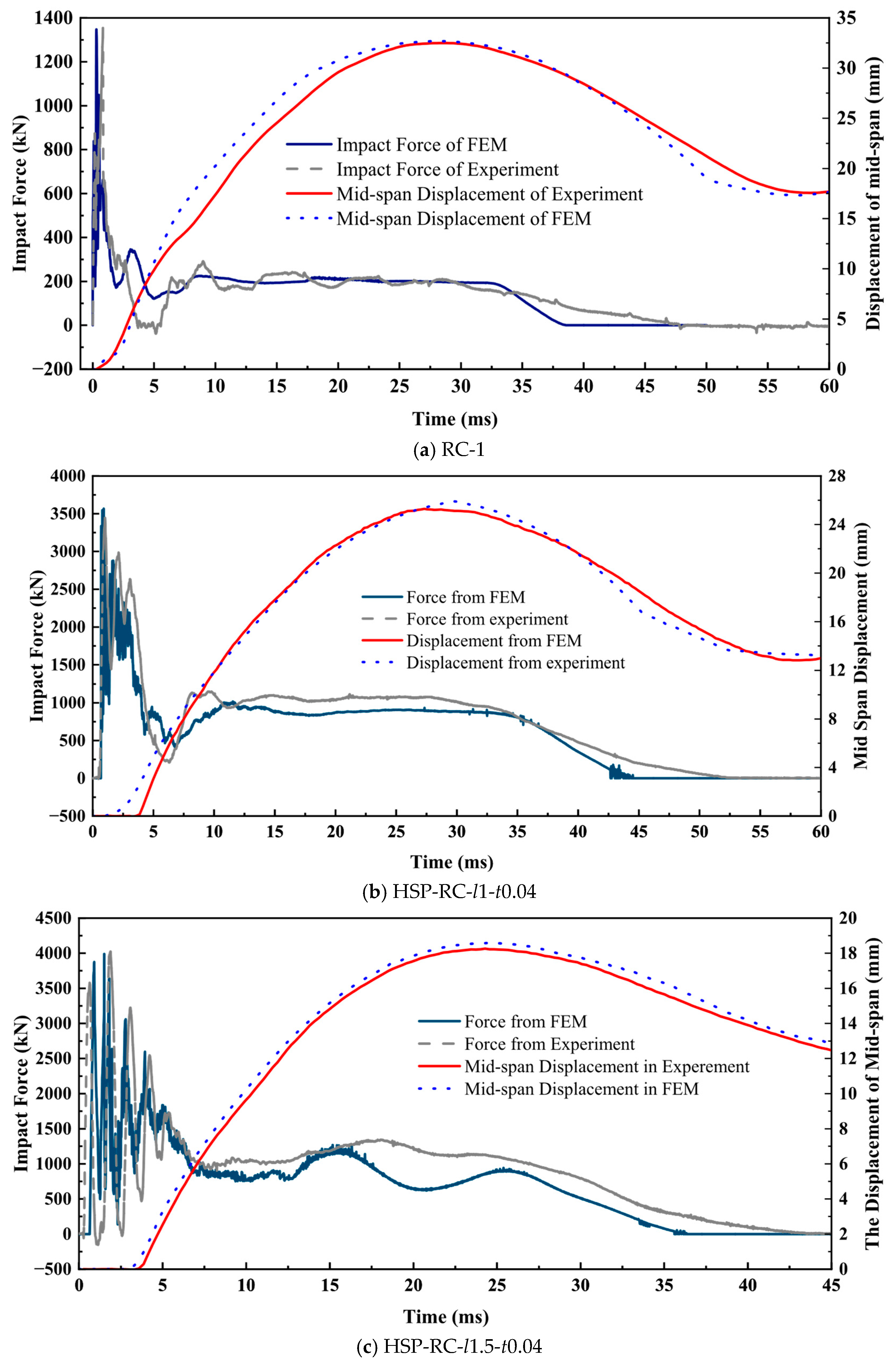
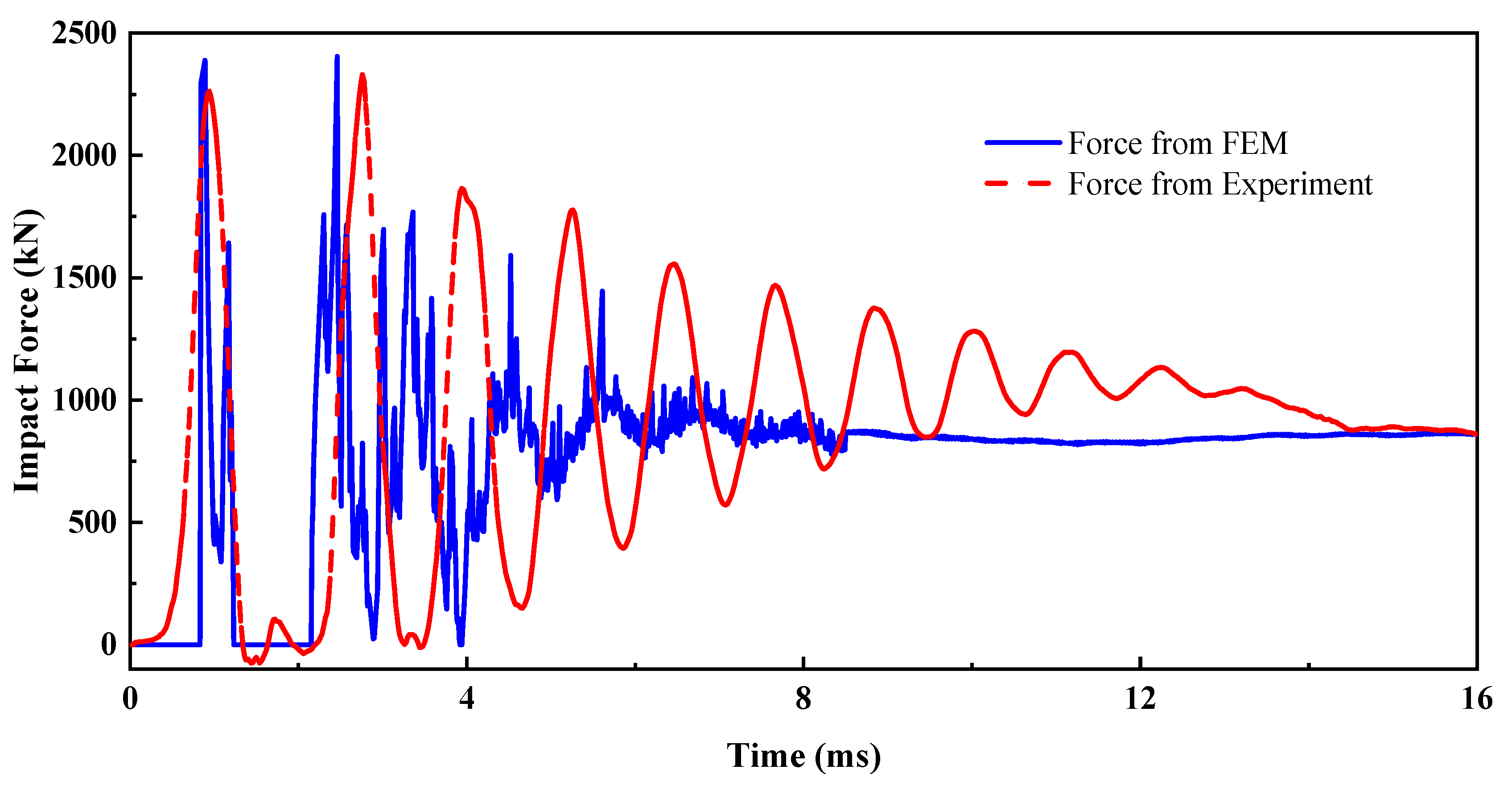
Impact force and mid-span displacement are important dynamic responses of structures under impact loads. Figure 11 compares the impact contact force and RC wall mid-span displacement output from each FEM with the curves collected in the experiment.
As the honeycomb cell’s edge length increases, the honeycomb core’s stiffness decreases, and the stiffness gradient between the honeycomb layer and aluminium panel or concrete increases, resulting in a more typical segmented impact force. From Figure 11, it can be seen that the FEMs established in this article can effectively simulate typical stages of the entire process, such as the zero value stage, fluctuation descent stage, and plateau stage of the impact force.
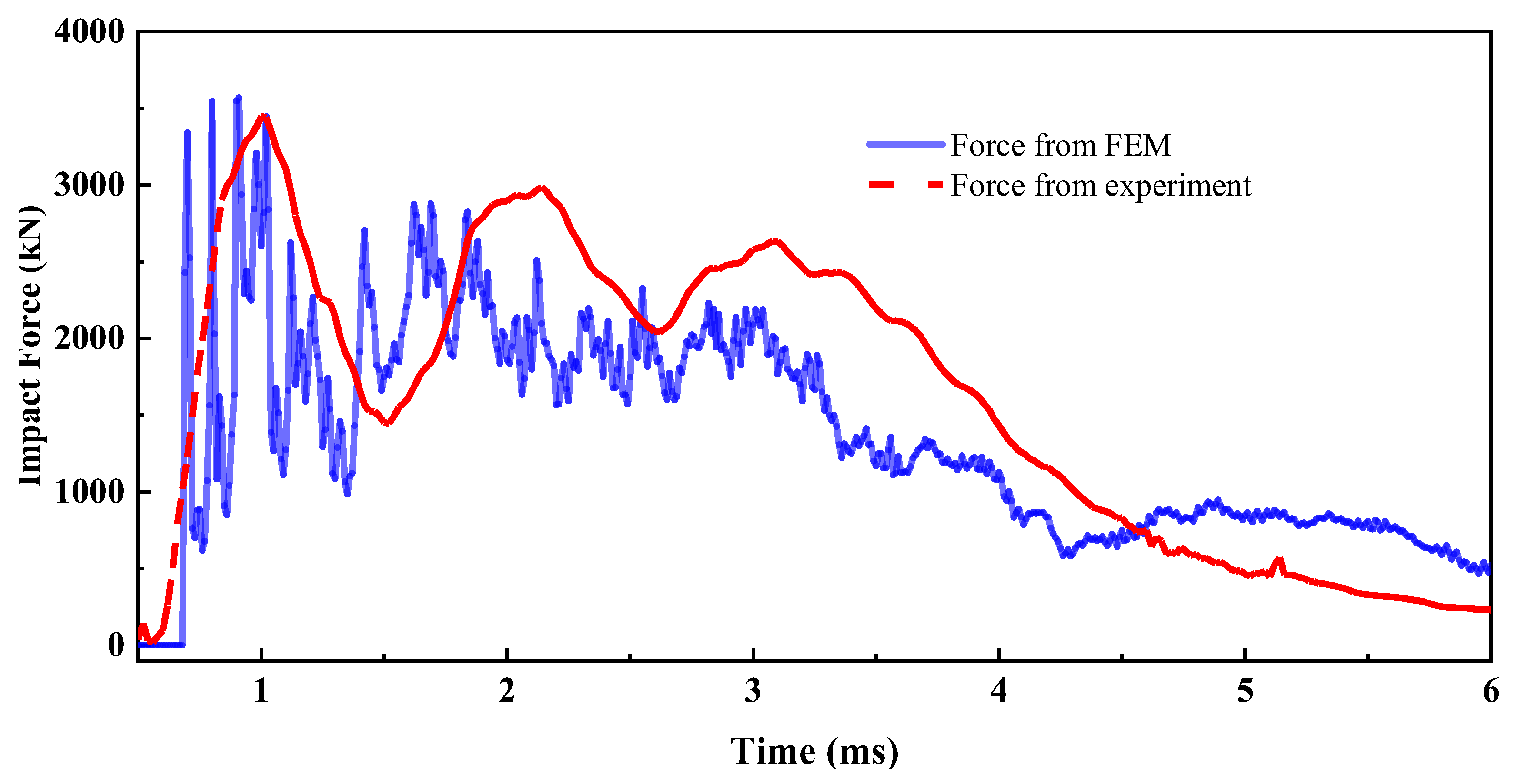
Taking the specimens HSP-RC-l1-t0.04 and HSP-RC-l2.5-t0.04 as examples, the comparison of the initial stage of impact force curves is shown in Figure 12 and Figure 13. It can be seen that FEMs can significantly simulate the overall trend and fluctuation details of impact force.
Based on the RC wall mid-span displacement in all FEMs, it can be concluded that when the RC wall is not protected or the honeycomb cell’s edge length is small, the overall stiffness of the honeycomb sandwich panel is high. In the early stage of impact, the slope of the RC wall mid-span displacement curve is large, indicating that the overall bending deformation rate of the RC wall is very fast, which is consistent with the conclusion obtained from the experiment that concrete damage is relatively rapid in the early stage of the impact process. The honeycomb sandwich panel reduces the occurrence of concrete damage in the early stage and plays a significant role in energy absorption and buffering.

3.2. Deformation of Honeycomb Sandwich Panel

The actual deformation of the honeycomb sandwich panel after the pendulum experiment is shown in Figure 14a (in the red box). The ideal deformation model of the honeycomb sandwich panel established in [26] is shown in Figure 14b. The surface deformation of the honeycomb sandwich panel output in the finite element model is shown in Figure 14c (in the black box).
The deformation of the honeycomb sandwich panel obtained in the FEMs is basically consistent with the actual indentation and conforms to the inference of the panel’s impact indentation area on the sandwich layer under ideal conditions.

3.3. Impact Protection Effect of Honeycomb Sandwich Panel on RC Wall

After the pendulum impacts the HSP-RC wall, it will cause a dynamic response of the HSP-RC wall and cause damage and destruction to the HSP-RC wall. By analysing the dynamic response of HSP-RC walls and the surface damage on HSP-RC walls, the impact protection effect of honeycomb sandwich panels can be analysed. This section mainly summarises the crack situation on HSP-RC and refers to the damage assessment methods in previous research and the concept of overall concrete damage (λ) [25]. The damage trend obtained from FEM is compared and analysed with the actual crack and mid-span displacement measured in experiments to verify the accuracy of the FEM and the impact protection effect of honeycomb sandwich panels.

3.3.1. Cracks

Cracks are the most intuitive reflection of the actual damage of RC walls. Statistical analysis of cracks in RC walls after impact can effectively reflect the degree of damage to the wall after the end of the impact load. Therefore, the concepts of actual cracks and concrete damage ratio on RC walls in FEM are comparable, and both can be used as evaluation parameters for the overall damage degree of RC walls.
(1)
Crack length
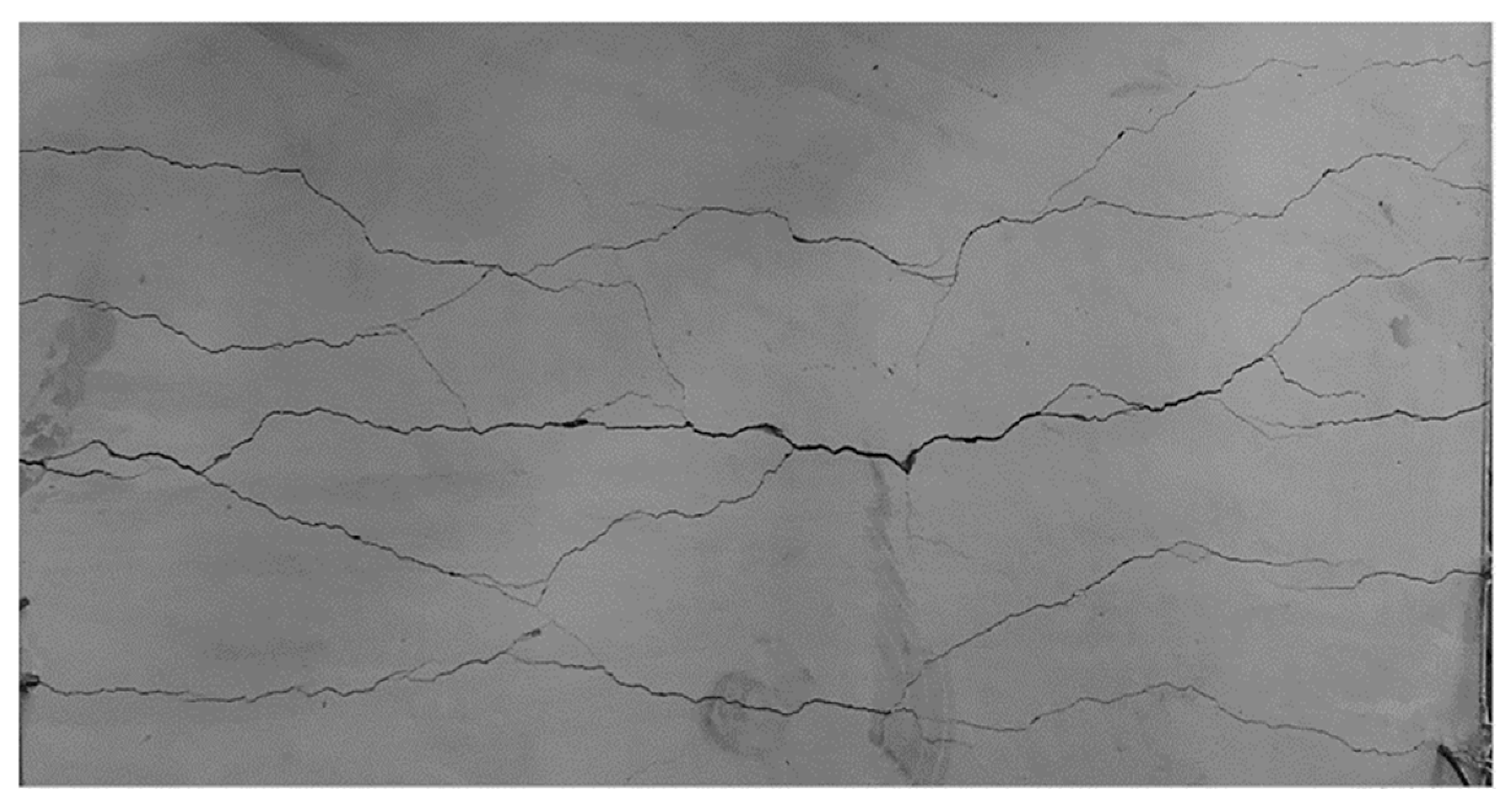
The cracks on the RC wall after impact are mainly concentrated in the middle of the back. Taking the distribution of cracks on the back of an RC wall (RC-1) after impact as an example, the final observable main crack group at the key crack locations of the specimen is shown in Figure 15.
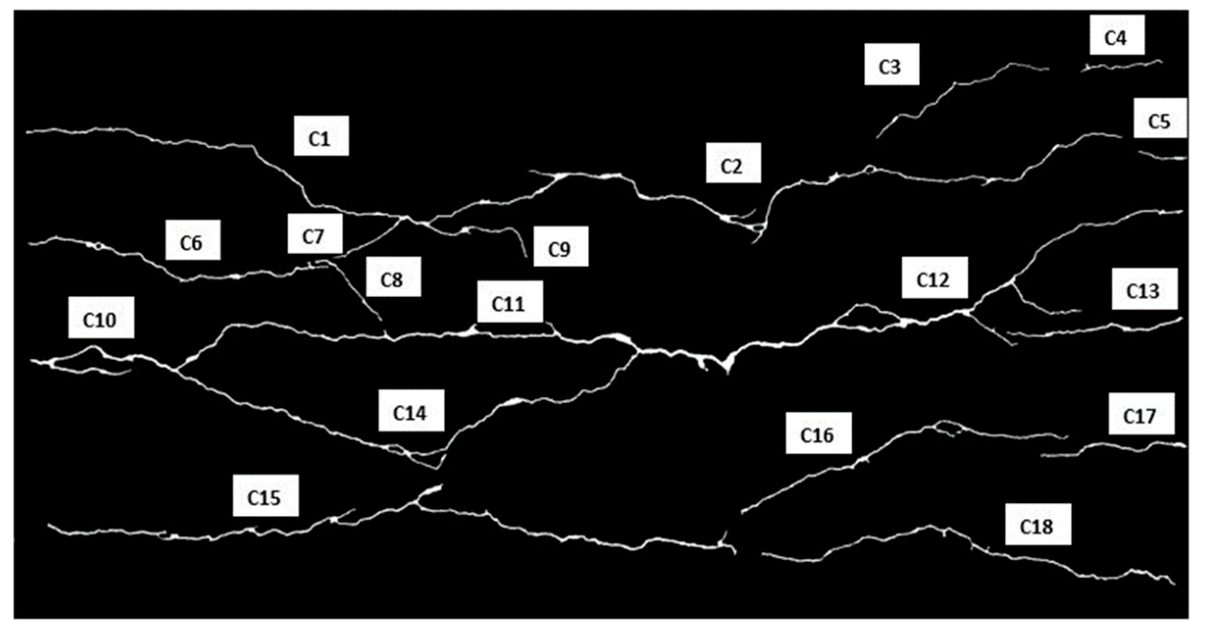
Basic image processing is carried out through the crack picture, including enhancing crack contrast, binarising to obtain binary crack images, labelling connected regions on binary images, identifying and numbering main cracks (as Figure 16, in the figure, C1–18 are the numbers of each crack.), calculating and summarising crack lengths, and obtaining the sum of crack lengths of all specimens, which are listed in Table 7.
Through the analysis of the cracks on the back of specimen RC-1 without added honeycomb sandwich panels, it can be seen that, in addition to the main cracks on the mid-span crack group, RC-1 also has many extended crack branches. However, for the convenience of statistics, when calculating the crack length, a large number of subtle extended cracks were ignored by setting the connected domain values. Therefore, the quantification of back cracks did not include small cracks in the RC-1 wall but only reflected the length of the main back cracks.
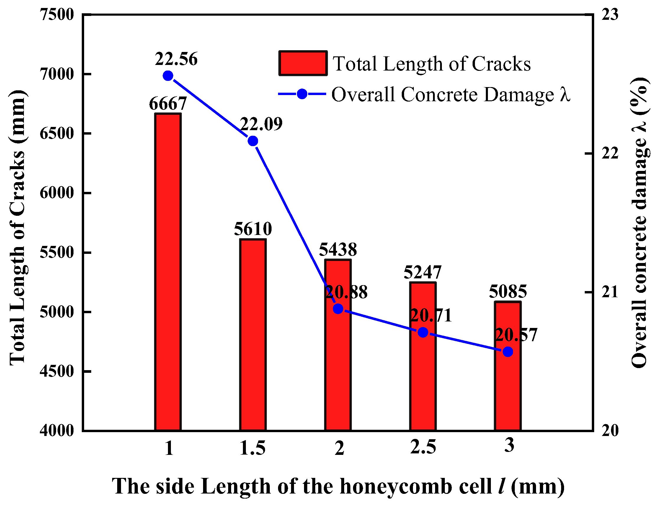
After adding honeycomb aluminium sandwich panels, there were almost no small extended cracks on the back of all specimens covered with honeycomb sandwich panels, except for the main crack at the mid-span. In the FEM, the concrete damage ratio of the RC-1 specimen was 63.93%. In comparison, the concrete damage ratio of the five specimens after adding honeycomb sandwich panels ranged from 20% to 23%, as shown in Figure 17. Moreover, as the honeycomb aperture increased, the concrete damage ratio decreased, indicating a decrease in the degree of concrete failure on the RC wall.
The trend of the main crack length of the RC wall after adding honeycomb sandwich panels is completely consistent with the concrete damage ratio obtained by the FEM (see Figure 16). The larger the pore size of the honeycomb layer, the smaller the honeycomb stiffness and the lower the degree of damage to the RC wall it protects. In the experiment, the honeycomb protection ability of the honeycomb hole with a wall thickness of 0.04 mm and a cell edge length less than 3 mm increases with the increase in the edge length.
However, as the aperture of the honeycomb increases, its protective ability does not increase uniformly. The protective ability rises in experiments rapidly when the edge length changes from 1 mm to 1.5 mm. However, due to inevitable production errors and defects in the actual honeycomb, the stiffness of the actual honeycomb may be slightly lower than the ideal stiffness (equivalent stiffness used in the FEMs). Therefore, the rapid increase in the protective ability of the honeycomb sandwich in the FEMs occurs between 1.5 mm and 2 mm.
(2)
Crack width
The honeycomb sandwich layer significantly reduces the maximum crack width on the RC wall during the impact process (summarised in Table 8), and all sandwich layers decrease the maximum crack width by over 57.5%. The honeycomb sandwich layer can effectively prevent the development of crack width on the RC wall and maintain stability during the impact process.
The analysis of the final residual maximum crack width of RC walls (summarised in Table 8) shows that the honeycomb sandwich layer significantly reduces the residual width of the main cracks on RC walls. Except for specimen HSP-RC-l1-t0.04, which decreased the residual crack width by 43.2%, all HSP-RC walls’ final residual crack width decreased by more than 63.2%.

3.3.2. Comparison of Residual Mid-Span Deformation and Concrete Damage Ratio

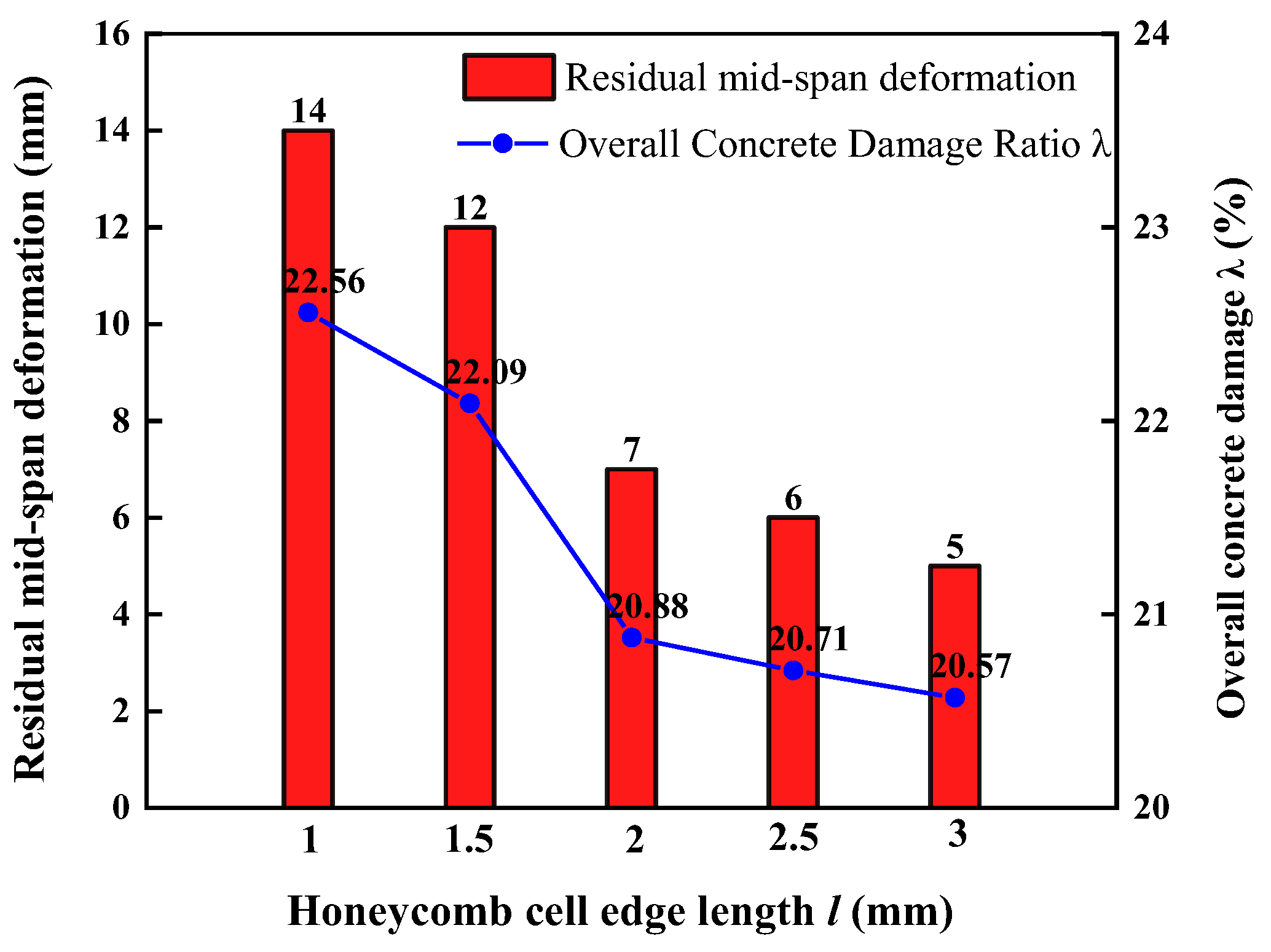
To further compare the degree of damage to RC walls after adding five different honeycomb sandwich panels, the overall deformation of RC walls can be analysed under the experimental phenomenon that adding sandwich panels can almost eliminate local damage. The values and trends of the residual deflection of the five specimens after the pendulum test, as well as the values and trends of the concrete damage ratio on the RC walls extracted from the FEMs, are shown in Figure 18.
After conducting pendulum tests on five specimens, the failure data of the RC wall were compared with the corresponding FEM results. It was found that the overall trend of different failure parameters of the RC wall with the variation in honeycomb cell edge length l was consistent in both cases. This phenomenon indicates that using the overall concrete damage ratio in the FEM calculation results to analyse and judge the degree of damage of RC components after impact is feasible and scientific, and the FEM in this article is accurate.

4. Impact Damage of HSP-RC Wall

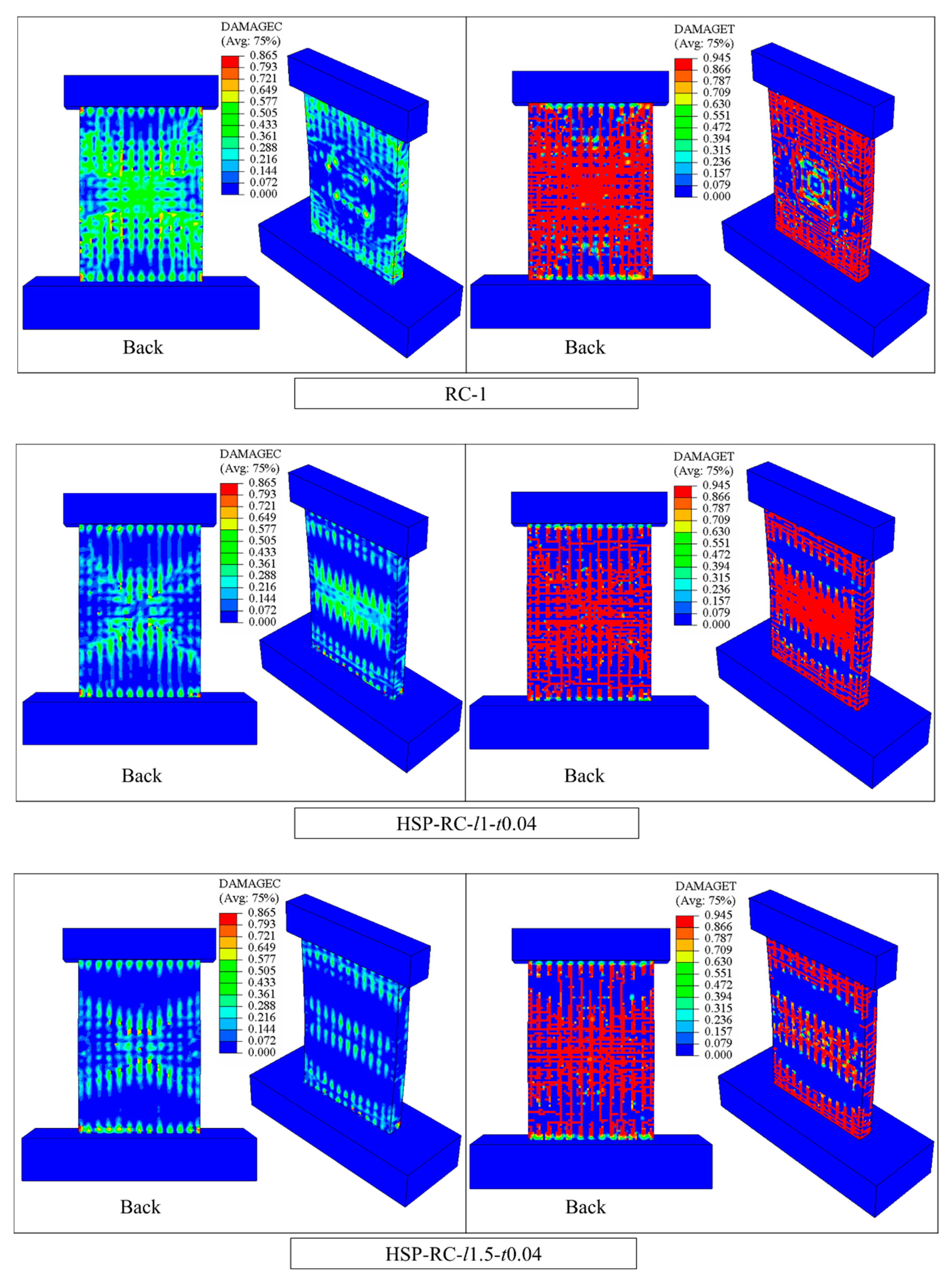
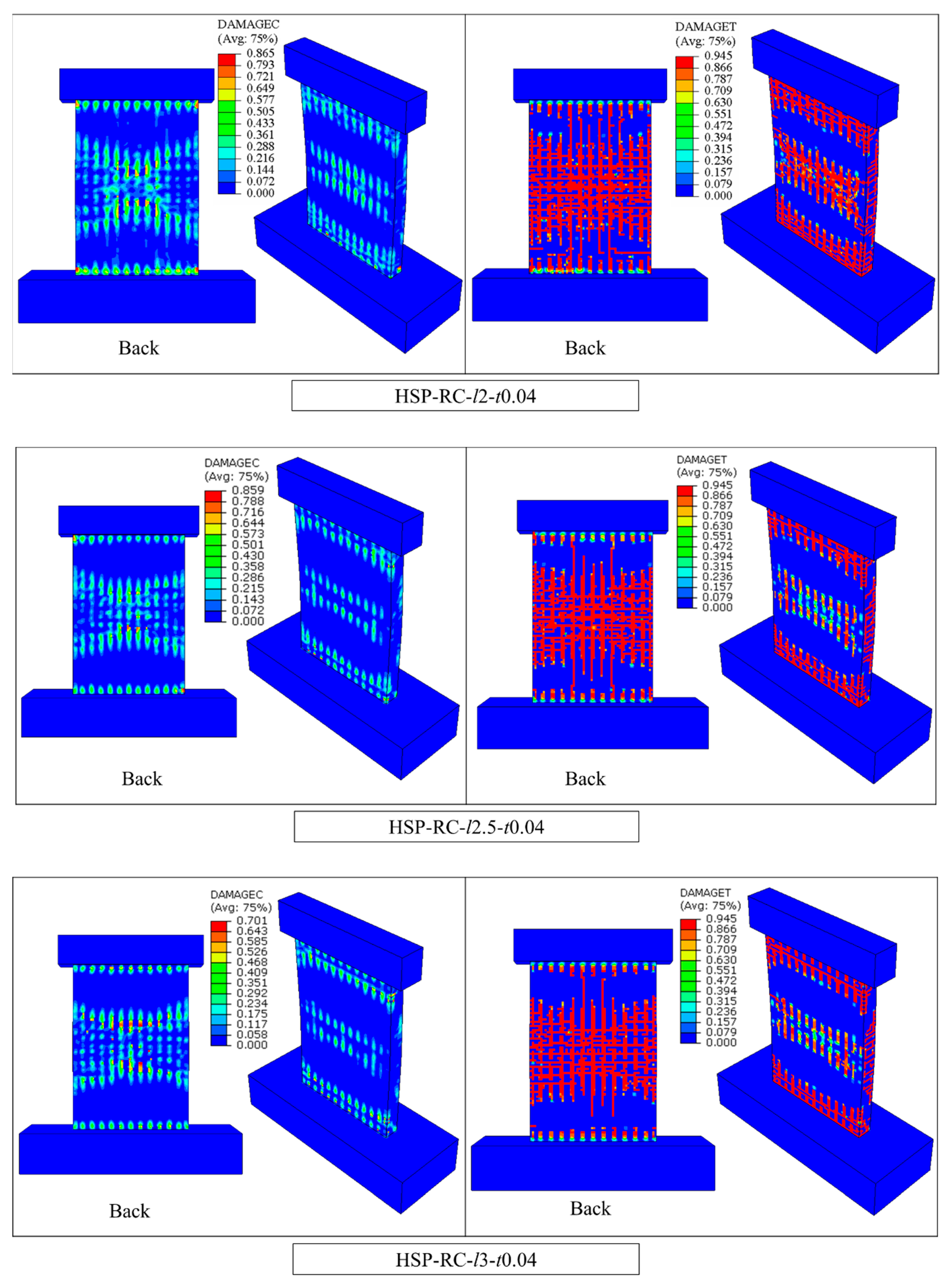
The surface concrete damage distribution of different HSP-RC walls is shown in Figure 19, which reflect the protective effect of different honeycomb sandwich panels on RC walls.
As shown in Figure 19, the RC wall damage after impact is related to the structural parameters of the honeycomb sandwich panel. The larger l value results in the lower stiffness of the honeycomb core layer, the better the energy absorption effect of the honeycomb core layer, and the better the protective effect of the honeycomb sandwich panel on the RC wall. The impact damage on the RC wall is lighter. The conclusion obtained from the FEM in this article is consistent with the conclusion obtained from the pendulum experiment, and the trend between the two is the same. Therefore, the modelling method of the HSP-RC wall established in this article can be used for the structural parameter analysis of HSP-RC walls in subsequent articles.

5. Conclusions

Based on the HSP-RC wall pendulum test, this article establishes a corresponding FEM, determines the correct method for establishing the HSP-RC wall FEM under impact, and solves the problem of difficulty in calculating the refined macroscopic honeycomb sandwich panel model (caused by the significant difference between the local honeycomb structure and the overall structure of the RC wall). The main conclusions are as follows:
(1)
The modelling method for HSP-RC walls established in this article can accurately simulate the pendulum impact test of an actual HSP-RC wall, using the concrete damage ratio parameter in the simulation to accurately describe the degree of damage of the RC wall.
(2)
The honeycomb sandwich layer significantly reduces the width and total length of the main cracks on RC walls. The corresponding manifestation in the simulation results is that the honeycomb sandwich layer can reduce the damage to the concrete of the RC wall after impact, and the reduction in concrete damage can reach more than half. Therefore, the porous energy-absorbing layer can effectively provide impact protection for reinforced concrete structures.
(3)
The modelling method adopted in this paper can only focus on the protected structure’s dynamic response, damage, and failure. It cannot be used for the special study of the honeycomb core’s energy absorption mechanism. Suppose it is necessary to improve or focus on researching the energy absorption characteristics and energy dissipation mechanisms of the honeycomb and the sandwich structures. In that case, impact compression tests, small-scale drop weight tests, and Split Hopkinson Pressure Bar (SHPB) tests must be conducted on honeycomb and honeycomb sandwich panel materials.

Author Contributions

Methodology, J.Z.; Software, R.Y. and D.S.; Formal analysis, K.W.; Investigation, R.Y. and T.Z.; Resources, J.Z.; Data curation, R.Z.; Writing—original draft, R.Y. and Y.G.; Writing—review & editing, J.Z.; Supervision, J.Z.; Funding acquisition, R.Y. All authors have read and agreed to the published version of the manuscript.

Funding

This research was supported by the Qingdao Huanghai university doctoral research Foundation project 2025boshi02. The support is gratefully acknowledged.

Data Availability Statement

The original contributions presented in this study are included in the article. Further inquiries can be directed to the corresponding author.

Conflicts of Interest

The authors declare that they have no known competing financial interests or personal relationships that could have appeared to influence the work reported in this paper.

References

  1. Shi, C.; Zhang, J.; Wang, X.; Liu, F.; Chen, W.; Ma, Z.; Liang, H.; Zhao, Y. Improving the Impact Resistance and Antisplash of Civil Air Defense Wall: Experiments and Finite-Element Simulation. J. Struct. Eng. 2023, 149, 04022238. [Google Scholar] [CrossRef]
  2. Dancygier, A.N.; Yankelevsky, D.Z.; Jaegermann, C. Response of high performance concrete plates to impact of non-deforming projectiles. Int. J. Impact Eng. 2007, 34, 1768–1779. [Google Scholar] [CrossRef]
  3. Liu, J.; Wu, C.; Su, Y.; Li, J.; Shao, R.; Chen, G.; Liu, Z. Experimental and numerical studies of ultra-high performance concrete targets against high-velocity projectile impacts. Eng. Struct. 2018, 173, 166–179. [Google Scholar] [CrossRef]
  4. Sadraie, H.; Khaloo, A.; Soltani, H. Dynamic performance of concrete slabs reinforced with steel and GFRP bars under impact loading. Eng. Struct. 2019, 191, 62–81. [Google Scholar] [CrossRef]
  5. Karim, R.; Shafei, B. Performance of fiber-reinforced concrete link slabs with embedded steel and GFRP rebars. Eng. Struct. 2021, 229, 111590. [Google Scholar] [CrossRef]
  6. Kühn, T.; Curbach, M.; Cadoni, E. Behavior of RC-slabs under impact-loading. EPJ Web Conf. 2015, 94, 01062. [Google Scholar] [CrossRef]
  7. Othman, H.; Marzouk, H. An experimental investigation on the effect of steel reinforcement on impact response of reinforced concrete plates. Int. J. Impact Eng. 2016, 88, 12–21. [Google Scholar] [CrossRef]
  8. Yılmaz, T.; Kıraç, N.; Anil, Ö.; Erdem, R.T.; Kaçaran, G. Experimental Investigation of Impact Behaviour of RC Slab with Different Reinforcement Ratios. KSCE J. Civ. Eng. 2019, 24, 241–254. [Google Scholar] [CrossRef]
  9. Radnić, J.; Matešan, D.; Grgić, N.; Baloević, G. Impact testing of RC slabs strengthened with CFRP strips. Compos. Struct. 2015, 121, 90–103. [Google Scholar] [CrossRef]
  10. Guo, H.; Du, C.; Chen, Y.; Li, D.; Hu, W.; Lv, X. Study on protective performance of impact-resistant polyurea and its coated concrete under impact loading. Constr. Build. Mater. 2022, 340, 127749. [Google Scholar] [CrossRef]
  11. Fallon, C.; McShane, G. Design of elastomer coatings for concrete impact damage mitigation. Int. J. Impact Eng. 2020, 146, 103700. [Google Scholar] [CrossRef]
  12. Zineddin, M.; Krauthammer, T. Dynamic response and behavior of reinforced concrete slabs under impact loading—ScienceDirect. Int. J. Impact Eng. 2007, 34, 1517–1534. [Google Scholar] [CrossRef]
  13. Almusallam, T.; Al-Salloum, Y.; Alsayed, S.; Iqbal, R.; Abbas, H. Effect of CFRP strengthening on the response of RC slabs to hard projectile impact. Nucl. Eng. Des. 2015, 286, 211–226. [Google Scholar] [CrossRef]
  14. Wang, T.; Qin, Q.; Wang, M.; Yu, W.; Wang, J.; Zhang, J.; Wang, T. Blast response of geometrically asymmetric metal honeycomb sandwich plate: Experimental and theoretical investigations. Int. J. Impact Eng. 2017, 105, 24–38. [Google Scholar] [CrossRef]
  15. Sun, G.; Zhang, J.; Li, S.; Fang, J.; Wang, E.; Li, Q. Dynamic response of sandwich panel with hierarchical honeycomb cores subject to blast loading—ScienceDirect. Thin-Walled Struct. 2019, 142, 499–515. [Google Scholar] [CrossRef]
  16. Zhang, D.; Fei, Q.; Zhang, P. Drop-weight impact behavior of honeycomb sandwich panels under a spherical impactor. Compos. Struct. 2017, 168, 633–645. [Google Scholar] [CrossRef]
  17. Ren, L.; Ma, H.; Shen, Z.; Wang, Y. Blast response of water-backed metallic sandwich panels subject to underwater explosion—Experimental and numerical investigations. Compos. Struct. 2019, 209, 79–92. [Google Scholar] [CrossRef]
  18. Lucas, J.W.; Conel, J.E.; Hagemeyer, W.A.; Garipay, R.R.; Saari, J.M. Lunar surface thermal characteristics from Surveyor 1. J. Geophys. Res. 1967, 72, 779–789. [Google Scholar] [CrossRef]
  19. Mohammadiha, O.; Beheshti, H.; Aboutalebi, F.H. Multi-objective optimisation of functionally graded honeycomb filled crash boxes under oblique impact loading. Int. J. Crashworthiness 2015, 20, 44–59. [Google Scholar] [CrossRef]
  20. Galehdari, S.; Khodarahmi, H. Design and analysis of a graded honeycomb shock absorber for a helicopter seat during a crash condition. Int. J. Crashworthiness 2016, 21, 231–241. [Google Scholar] [CrossRef]
  21. Pan, J.; Fang, H.; Xu, M.C.; Xue, X.Z. Dynamic performance of a sandwich structure with honeycomb composite core for bridge pier protection from vehicle impact. Thin-Walled Struct. 2020, 157, 107010. [Google Scholar] [CrossRef]
  22. Pan, J.; Fang, H.; Xu, M.C.; Wu, Y.F. Study on the performance of energy absorption structure of bridge piers against vehicle collision. Thin-Walled Struct. 2018, 130, 85–100. [Google Scholar] [CrossRef]
  23. Xu, S.; Liu, Z.; Li, J.; Yang, Y.; Wu, C. Dynamic behaviors of reinforced NSC and UHPC columns protected by aluminum foam layer against low-velocity impact. J. Build. Eng. 2021, 34, 101910. [Google Scholar] [CrossRef]
  24. Song, J.; Hu, D.; Luo, S.; Liu, W.; Wang, D.; Sun, Q.; Zhang, G. Energy-absorption behavior of metallic hollow sphere structures under impact loading. Eng. Struct. 2021, 226, 111350. [Google Scholar] [CrossRef]
  25. Yang, R.; Qu, D.; Zhang, J.; Zhao, G.; Gu, C. Numerical evaluation of impact resistance of reinforced concrete walls. Structures 2024, 64, 106518. [Google Scholar] [CrossRef]
  26. Yang, R.; Qu, D.; Zhang, J. Experimental Study on the Impact Resistance Performance of Civil Air Defense RC Walls Protected by Honeycomb Sandwich Panels. Buildings 2024, 14, 2293. [Google Scholar] [CrossRef]
  27. Zhang, T.; Hou, Z.; Li, X.; Chen, Q. Research on the calculation of model parameters for concrete plastic damage model in ABAQUS. Chin. J. Comput. Mech. 2024, 41, 1130–1137. [Google Scholar] [CrossRef]
  28. Omairey, S.; Dunning, P.; Sriramula, S. Development of an ABAQUS plugin tool for periodic RVE homogenization. Eng. Comput. 2019, 35, 567–577. [Google Scholar] [CrossRef]
  29. Harrigan, J.; Reid, S.; Peng, C. Inertia effects in impact energy absorbing materials and structures. Int. J. Impact Eng. 1999, 22, 955–979. [Google Scholar] [CrossRef]
  30. Hong, S.; Pan, J.; Tyan, T.; Prasad, P. Dynamic crush behaviors of aluminum honeycomb specimens under compression dominant inclined loads. Int. J. Plast. 2008, 24, 89–117. [Google Scholar] [CrossRef]
  31. Bambach, M. Design of hollow and concrete filled steel and stainless steel tubular columns for transverse impact loads. Thin-Wall Structrue 2011, 49, 1251–1260. [Google Scholar] [CrossRef]
  32. Al Fuhaid, A.; Abu Sohel, K.M. Arifuzzaman The Effect of Strengthening Methods on the Performance of Reinforced Concrete Columns against Vehicle Impact. Appl. Sci. 2022, 12, 1382. [Google Scholar] [CrossRef]
  33. Do, T.V.; Pham, T.M.; Hao, H. Proposed design procedure for reinforced concrete bridge columns subjected to vehicle collisions. Structures 2019, 22, 213–229. [Google Scholar] [CrossRef]
  34. Do, T.V.; Pham, T.M.; Hao, H. Impact Response and Capacity of Precast Concrete Segmental versus Monolithic Bridge Columns. J. Bridg. Eng. 2019, 24, 1–28. [Google Scholar] [CrossRef]
  35. Pham, T.M.; Chen, W.; Elchalakani, M.; Do, T.V.; Hao, H. Sensitivity of lateral impact response of RC columns reinforced with GFRP bars and stirrups to concrete strength and reinforcement ratio. Eng. Struct. 2021, 242, 112512. [Google Scholar] [CrossRef]
Figure 1. Honeycomb structure and three directions.
Buildings 15 03921 g001
Figure 2. Honeycomb sandwich structure.
Buildings 15 03921 g002
Figure 3. HSP-RC wall.
Buildings 15 03921 g003
Figure 4. Concrete constitutive model.
Buildings 15 03921 g004aBuildings 15 03921 g004b
Figure 5. Calculation results of honeycomb RVE.
Buildings 15 03921 g005
Figure 6. Two standardised material constant values for honeycomb aluminium [31].
Buildings 15 03921 g006
Figure 7. Assembly of the pendulum impact HSP-RC wall FEM.
Buildings 15 03921 g007
Figure 8. Constraints, velocity in FEM.
Buildings 15 03921 g008
Figure 9. Element.
Figure 9. Element.
Buildings 15 03921 g009
Figure 10. Embedded.
Buildings 15 03921 g010
Figure 11. Impact force and mid-span displacement of FEMs and experiments.
Buildings 15 03921 g011aBuildings 15 03921 g011b
Figure 12. Impact force fluctuation during the initial collision of HSP-RC-l1-t0.04.
Buildings 15 03921 g012
Figure 13. Impact force fluctuation during the initial collision of HSP-RC-l2.5-t0.04.
Buildings 15 03921 g013
Figure 14. Comparison of the impact deformation in compression zone. (a) Actual deformation [26]. (b) Ideal indentation model [26] 2024. (c) Deformation in FEMs’ results.
Buildings 15 03921 g014
Figure 15. Main crack group of RC wall (RC-1).
Buildings 15 03921 g015
Figure 16. Processed crack image and cracks’ numbers (RC-1).
Buildings 15 03921 g016
Figure 17. Trend of experimental cracks and concrete damage ratio of FEM.
Buildings 15 03921 g017
Figure 18. Trend of deformation and concrete damage ratio of the specimens.
Buildings 15 03921 g018
Figure 19. Surface concrete damage distribution of different HSP-RC walls.
Buildings 15 03921 g019aBuildings 15 03921 g019b
Table 1. Parameters of CDP model.
Dilation Angle ΨEccentricity ∈ γ b c σ = f b c / f c KViscosity Coefficient
37.501.282/30
Table 2. Yield strength and ultimate strength of rebars.
Diameter of Rebars (mm)Yield Strength fy (MPa)Ultimate Strength fu (MPa)Elongation (%)
6 mm42560321.4
8 mm44261422.9
20 mm47061022.3
22 mm44861122.4
25 mm45461520.7
Table 3. Property parameters of aluminium alloy plate.
Board Thickness ErrorTensile StrengthYield StrengthElongationDensity
±0.1 mm212 MPa148 MPa15.5%2725 kg/m3
Table 4. Mechanical property parameters of aluminium foil.
Average ThicknessTensile StrengthYield StrengthYoung’s ModulusElongationDensityPoisson’s Ratio
0.04 mm299 MPa27.6 MPa69 MPa3%2690 kg/m30.33
Table 5. Equivalent material parameters of honeycomb calculated by RVE (unit: Pa, m).
ModulusE11E22E33G12G13G23
Computed values631,348.97893,448.344,328,243.6040,763.034763.49542,515.51
Table 6. Summary of wall specimen parameters.
Structure ParametersRC-1HSP-RC-l1-t0.04HSP-RC-l1.5-t0.04HSP-RC-l2-t0.04HSP-RC-l2.5-t0.04HSP-RC-l3-t0.04
l (mm)/11.522.53
t (mm)/0.040.040.040.040.04
H (mm)/33333
h (mm)/4040404040
v (m/s)2.32.32.32.32.32.3
m (t)222222
Ek (J)5290.05290.05290.05290.05290.05290.0
Note: “/” indicates no addition of honeycomb sandwich panel.
Table 7. Statistics of cracks in different specimens.
Specimen NumberRC-1HSP-RC-l1-t0.04HSP-RC-l1.5-t0.04HSP-RC-l2-t0.04HSP-RC-l2.5-t0.04HSP-RC-l3-t0.04
Total length of cracks (mm)7009.836667.205612.855438.605247.505085.08
Table 8. Summary of maximum crack widths for each specimen.
Specimen NumberMaximum Crack Width
During the Impact ProcessFinal Status
RC-17.49 mm5.69 mm
HSP-RC-l1-t0.04/3.23 mm
HSP-RC-l1.5-t0.042.89 mm1.53 mm
HSP-RC-l2-t0.043.18 mm2.09 mm
HSP-RC-l2.5-t0.042.95 mm1.84 mm
HSP-RC-l3-t0.042.60 mm1.61 mm
Note: “/” indicates that it could not be collected.
Disclaimer/Publisher’s Note: The statements, opinions and data contained in all publications are solely those of the individual author(s) and contributor(s) and not of MDPI and/or the editor(s). MDPI and/or the editor(s) disclaim responsibility for any injury to people or property resulting from any ideas, methods, instructions or products referred to in the content.