Abstract
To mitigate and control the seismic damage risk of high-speed railway bridges and enhance their post-earthquake reparability, a prefabricated multi-layer parallel-connected slit steel plate shear damper is proposed by utilizing the energy absorption capacity of flexure–shear coupled deformation in dampers. A theoretical model for calculating the stiffness and load-bearing capacity of the proposed damper was established and validated through detailed finite element simulations. The results demonstrate that the damper exhibits stable energy dissipation efficiency under cyclic loading, along with a gradual reduction in post-yield stiffness. Subsequently, a numerical model of the high-speed railway track–bridge-damper systems (HSRTBDS) was developed, incorporating the contribution of the proposed damper to quantify its control over the seismic response of the HSRTBDS. The findings indicate that the damper effectively reduces the seismic responses of the girders, rail fasteners, and track slabs, with a maximum deformation reduction exceeding 30% in the supporting structures. However, the deformation and damage of the bridge piers slightly increased, though they remained within acceptable safety limits. The damper showed limited influence on the damage to rails, fasteners, and shear key slots. Overall, the effectiveness of the proposed damper in controlling the structural response of HSRTBD has been demonstrated and validated, providing insights for the seismic design of high-speed railway bridges in high-intensity seismic zones.
1. Introduction
China’s high-speed railway bridges have undergone rapid development, with the “bridge-dominant approach” serving as a defining feature of the nation’s high-speed rail systems. On certain railway lines, the proportion of bridges has even reached 80% [1]. However, as high-speed railway construction extends into central and western regions, where active fault zones are densely distributed, seismic activity now poses significant challenges to both the structural service integrity of railway bridges and the operational stability of high-speed trains [2,3]. An abrupt seismic event would inflict extensive damage and destruction upon building structures, high-speed railways, and railway bridges, severely compromising structural safety while causing substantial casualties and incalculable losses. This circumstance thus establishes seismic damping design as a critical domain within bridge seismic engineering. Seismic damping design prioritizes the synergistic interaction between dampers and the primary structural system, along with ensuring the reliability and durability of the dampers themselves [4,5]. This approach facilitates a paradigm shift in design philosophy—from merely “ensuring safety” to comprehensively enhancing “functional recoverability” and implementing integrated life-cycle management of structures [6].
Seismic mitigation technology serves as a desirable measure for enhancing the overall structural seismic performance, primarily achieved through vibration control devices [7,8]. Energy dissipation devices are categorized into active control devices, semi-active control devices, and passive control devices. Active control devices [9,10] necessitate external energy input, typically employing smart materials integrated with control algorithms to dynamically regulate structural parameters such as stiffness and damping. Xing et al. [9] formulated an optimal feedback control model for externally installed active tuned mass damper (ATMD) systems and investigated the parametric influence of selected input variables on control efficacy under combined seismic and wind loading conditions. Amjadian et al. [11] designed an electromagnetic friction damper for semi-active control of continuous girder bridges. Numerical simulations demonstrated that this solution effectively restricts deck movement, thereby preventing unseating. However, active control devices exhibit reduced reliability under extreme loading conditions due to their numerous control components, substantial power requirements, and stringent computational precision demands, necessitating further development.
Semi-active control devices can regulate operational states and modify dynamic characteristics to accommodate varying structural responses with minimal energy consumption, utilizing external load and structural response data. Within this domain, Magnetorheological dampers [12,13] have garnered significant attention due to their low energy consumption, structural simplicity, and rapid adjustability.
Passive devices currently represent the most extensively utilized control mechanisms, offering advantages including low cost, superior mechanical performance, and enhanced durability. Their operational principle entails requiring no external energy input, whereby under external excitation, these devices undergo deformation to dissipate seismic energy through energy dissipation mechanisms. Commonly implemented passive control devices include viscous dampers [14,15,16], viscoelastic dampers [17,18], friction dampers [19,20], and metallic dampers [21,22,23].
Currently, research on energy dissipation devices predominantly focuses on building structures and highway bridges, with limited applications in high-speed railway bridges. Guo et al. [24] proposed a novel isolation bearing system integrating an S-shaped steel-plate damper with a spherical steel bearing. This innovative system demonstrates efficacy in dissipating seismic energy to prevent displacement in high-speed railway bridge system (HSRTBS). Xie et al. [25] proposed the U-shaped metal dampers, developing a simplified analytical model to characterize the hysteresis behavior under biaxial deformation. Zhai et al. [26] proposed a novel S-shaped steel plate damper and validated it through loading tests. As critical infrastructure, high-speed railway bridges serve essential functions in post-earthquake rescue operations. Consequently, implementing rapidly replaceable energy dissipation devices substantially enhances bridge seismic resilience [27,28,29,30,31,32].
To improve the seismic response of high-speed railway simply supported girder bridges, this study proposes a prefabricated multi-layer parallel-connected slit steel plate shear damper (SSPSD) characterized by anti-buckling capacity and replaceability. Theoretical models establishing its stiffness and load-bearing capacity alongside finite element simulation analyses were developed to thoroughly investigate the damper’s mechanical properties. A coupled CRTS II slab track–simply supported girder bridge–damper system (HSRTBDS) was constructed to quantify the influence of beam-rail constraints on seismic mitigation efficiency. Furthermore, based on 40 amplitude-adjusted ground motion records, this research elucidates the mapping relationship between damper and seismic responses at critical bridge sections.
2. Prefabricated Multi-Layer Parallel-Connected Slit Steel Plate Shear Damper
2.1. Configuration and Fabrication
The SSPSD is a metallic energy dissipation device engineered based on shear deformation principles. As depicted in Figure 1, its primary structure comprises Q235 steel components welded into an integrated assembly. Core constituents include three slitted energy dissipation plates, anti-buckling spacers, and external angle steel restraint frames. The energy dissipation plates serve as the principal working units, absorbing seismic energy through in-plane shear deformation. Spacers are interposed between adjacent plates with thickness slightly exceeding that of the plates to reserve deformation clearance, thereby inhibiting out-of-plane buckling while minimizing frictional interference. Angle steel frames are welded externally to the plate assembly, enhancing global stability through lateral stiffness augmentation. This modular design permits calibrated adjustment of load-bearing capacity via addition or removal of dissipation plates, accommodating diverse seismic performance requirements across application scenarios.
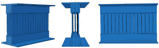
Figure 1.
Configuration of SSPSD.
2.2. Mechanical Properties
From the perspective of mechanical response zoning, the energy dissipation plate of SSPSD can be partitioned into slit-perforated and non-slit regions. The non-slit region exhibits reduced height-to-width ratios, undergoing predominantly pure shear deformation under external loading, with uniform stress distribution. Conversely, the slit-perforated region demonstrates significantly increased height-to-width ratios, where bending moment concentration at its ends forms plastic hinges, resulting in a coupled flexural-shear deformation mechanism that constitutes the primary energy dissipation zone.
Based on the principles of energy equivalence and plastic hinge theory, the critical mechanical parameters of the damper can be derived. The initial stiffness K is calculated through the series combination of shear stiffness in the slit-perforated region and flexural stiffness in the non-slit region:
where k denotes the rectangular section coefficient; H represents the height of the SSPSD; m indicates the number of slit rows; h defines the height of steel plate strips within the slit-perforated region; G signifies the material’s shear modulus; B corresponds to the damper width; b specifies the width of steel plate strips in the slit-perforated region; n enumerates the quantity of steel plate strips per slit row; α quantifies the aspect ratio (h/b) of said strips; E designates the material’s elastic modulus; and t measures the damper thickness.
The yield load capacity Qy corresponds to the shear force at the formation of the first plastic hinge, determined by the elastic section modulus We at the end section and the yield strength fy of the steel, calculated as
where My denotes the elastic moment at the yield threshold, fy represents the material’s yield stress, and We indicates the elastic section modulus at the extremity of the steel plate strip.
where Mu signifies the magnitude of the plastic moment; and Wp denotes the plastic section modulus at the extremity of the steel plate strip.
2.3. Finite Element Modelling
To validate the reliability of the theoretical model, a refined finite element model was developed using ABAQUS 2024 software. The specific modeling procedure comprised the following steps: First, solid models of the energy dissipation plates, spacers, and angle steels were constructed based on geometric dimensions, which were then translationally assembled into an integrated damper. Among them, the energy dissipation plate measures 450 mm in length, 300 mm in height, and 6 mm in thickness. It features 14 slit zones at its center, each with a length of 2 mm and a height of 138 mm, spaced at intervals of 28 mm. The spacer plate has dimensions of 450 mm in length, 65 mm in height, and 15 mm in thickness. The angle steel measures 450 mm in length, 708 mm in height, and 8 mm in thickness. The material constitutive relationship employed a bilinear kinematic hardening model for Q235 steel, with elastic modulus E = 210 GPa, Poisson’s ratio ν = 0.3, yield strength fy = 235 MPa, and a 2% hardening ratio.
For contact settings: Normal hard contact and tangential frictionless behavior were defined between energy dissipation plates to simulate spacer isolation effects; “Tie” constraints simulated welded connections between angle steels and energy dissipation plates, with master-slave surface selection following the principle illustrated in Figure 2a (master surface: angle steel inner faces; slave surface: plate edges) to avoid constraint redundancy. The “Tie” constraint method was adopted to replace actual welded connections, which helps improve the result curves and has a negligible impact on the simulation outcomes. All other contact interfaces were defined using a general contact algorithm. Subsequently, a reference point (RP-1) was defined on the top surface of the damper. As shown in Figure 2b, in the load module, boundary conditions and load configurations were applied to the PPSPD finite element model. Both constraints and external loads were assigned to reference point RP-1. The assembly components were partitioned, with all degrees of freedom at the bottom surface of the damper fully constrained, while the top surface was constrained in all degrees of freedom except for translation in the Z-direction. A displacement-controlled load was applied at RP-1.Additional partitioning operations were performed to optimize mesh generation quality. Seed sizes were defined based on component dimensions and criticality: the global mesh size was set to 10 mm, while the energy dissipation plate was assigned a mesh size of 5 mm.
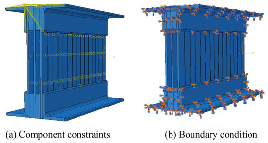
Figure 2.
Component constraints and boundary condition.
Figure 3 specifies the test loading protocol utilizing triangular waveform displacement control. The amplitude sequence was progressively applied as follows: 1 mm, 2 mm, 4 mm, 6 mm, 8 mm, 10 mm, 15 mm, 20 mm, 25 mm, 30 mm, 40 mm, 50 mm, and 60 mm.
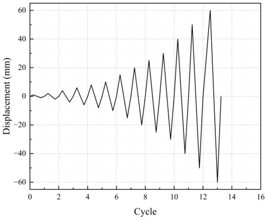
Figure 3.
Test loading protocol.
Figure 4 presents the finite element simulation results of the SSPSD. As shown in Figure 4a–c, the hysteresis curves of the SSPSD under different amplitudes are displayed. The damper exhibits stable hysteretic behavior characterized by continuous and full hysteresis loops without any pinching effect. The increase in displacement amplitude leads to a gradual expansion of the hysteresis loop area, demonstrating stable energy absorption and dissipation capacity under large deformations, which meets the core requirements for seismic resistance and vibration mitigation. The SSPSD exhibits high initial stiffness. During multiple cyclic loading tests, the slope of the curve in subsequent cycles shows a slight reduction compared to the first cycle, indicating minor stiffness degradation. However, the overall shape of the hysteresis loops remains stable without significant pinching or contraction. The loading and unloading curves in both positive and negative directions are nearly identical, demonstrating highly symmetric behavior. This confirms that the damper’s mechanical performance is remarkably consistent in both tension and compression states, with no noticeable bias. Overall, the damper demonstrates ideal stiffness characteristics and can play a critical role in protecting the primary structure from seismic damage. Figure 4d presents the finite element simulation stress contour of the SSPSD, illustrating pronounced shear deformation in the energy dissipation plates with significant stress concentration at their extremities. This confirms efficient structural performance mobilization within these critical components.
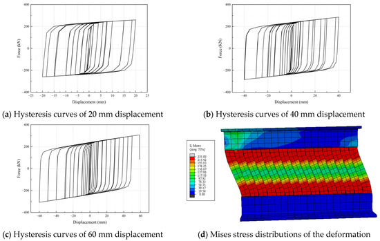
Figure 4.
Finite element simulation results.
2.4. Research Limitations and Future Prospects
This study utilizes a combined methodology of theoretical derivation and numerical simulation, with cross-validation between these approaches enhancing the reliability of the conclusions. It should be noted, however, that the absence of experimental validation constitutes a limitation that requires explicit discussion regarding its implications. The lack of experimental verification may restrict the direct applicability of the findings in real physical scenarios. Although theoretical and numerical methods are capable of revealing general underlying principles, actual systems are subject to nonlinear disturbances, uncertainties in boundary conditions, and other complicating factors that may lead to deviations between empirical observations and theoretical predictions.
That said, the strong consistency between the theoretical framework and numerical outcomes achieved in this study ensures a high degree of internal validity and offers a mechanistic interpretation of the relevant phenomena. Future work will prioritize the design of experimental protocols, with particular emphasis on examining the discrepancies between modeling assumptions and interference factors present in practical environments, thereby further validating and extending the conclusions established here. The present findings nevertheless provide a theoretical predictive foundation and guidance for parameter optimization in subsequent experimental research.
3. The High-Speed Railway Track-Bridge System with SSPSDs
3.1. Numerical Model of HSRTBS with SSPSD
The seismic performance evaluation of high-speed railway track-bridge-damper systems (HSRTBDS) requires comprehensive integration of complex track-bridge coupling effects [33,34,35]. As depicted in Figure 5, this study investigates a five-span simply supported high-speed railway bridge with uniform pier heights (14 m) and CRTS II slab track, where each girder spans 32.6 m. The bridge incorporates 50 m transition sections at both ends and 90 m embankment segments. Utilizing design blueprints and technical specifications, spatial finite element models were developed in opensees: a baseline track-bridge system model and an enhanced HSRTBDS model incorporating SSPSDs [36].
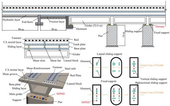
Figure 5.
Schematic representation of HSRTBS with SSPSDs.
The high-speed railway track-bridge system comprises two primary subsystems: the bridge structure and the track structure. The bridge structure includes girders, piers, bearings, and abutments. The track structure consists of longitudinally continuous components—rails, fasteners, track slabs, and CA mortar layers—with additional elements specific to bridge sections: base slabs, sliding layers, shear reinforcement bars, shear keys, and lateral restraining blocks [37]. In bridge-approach transition zones, the track incorporates base slabs, sliding layers, friction plates, and end anchors. For embankment sections, the track structure is supported by a hydraulically bound layer. A representative finite element model of this integrated system is illustrated in Figure 6.
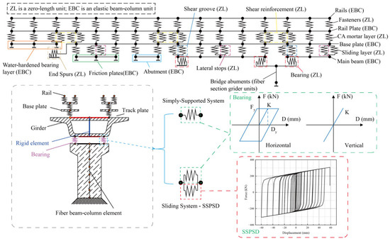
Figure 6.
Schematic diagram of the finite element model of the HSRTBDS.
Piers were modeled using displacement-based fiber-section beam-column elements [38,39]: cover concrete employed the Concrete01 material model [40], while core concrete utilized Concrete04 to account for strength enhancement from confining reinforcement [41,42]. Reinforcement bars were simulated with the Steel02 kinematic hardening model [43]. Given the high longitudinal and transverse stiffness of abutments, their deformability was neglected and represented via rigid links in the finite element model [44]. Bearings were simulated with zero-length elements. For this simply supported bridge, four bearing types were implemented at pier tops: bidirectional sliding bearings, transverse sliding bearings, longitudinal sliding bearings, and fixed bearings. Since seismic damage predominantly occurs in the horizontal direction, the vertical constitutive behavior was simplified as linear elastic. The horizontal force–deformation response adopted an idealized elastic-perfectly plastic model, with yield force equivalent to the bearing’s horizontal design capacity [45].
Research confirms that rails, track slabs, base slabs, and friction plates typically remain elastic under seismic forces, warranting their simulation as linear elastic beam elements with material properties detailed in Table 1 [45]. Interlayer components—including fasteners, CA mortar layers, sliding layers, shear keys, shear reinforcement bars, and lateral restraining blocks—were modeled using zero-length elements. Specifically, CHN60 rails and WJ-8 fasteners were implemented, with the latter exhibiting horizontal elastic-perfectly plastic behavior and vertical linear elasticity. Precast C55 concrete track slabs were arranged continuously along the longitudinal bridge axis, interconnected via tensioning devices. The hydraulically bound subgrade layer (elastic modulus 1.8 GPa, Poisson’s ratio 0.2, density 2500 kg/m3) bearings the track structure in embankment sections. The CA mortar layer, serving as a buffer between track slabs and base slabs, was modeled as an elastic-perfectly plastic material due to its susceptibility to shear failure under horizontal loading [46]. To ensure longitudinal force transfer between the track system and girders, shear keys and reinforcement bars were installed above fixed bearings. Lateral restraining blocks positioned along bridge decks constrain transverse displacement of base/track slabs while permitting vertical movement; their constitutive behavior exhibit zero longitudinal stiffness, transverse elastic-perfectly plastic response, and negligible vertical stiffness. Corresponding material parameters are provided in Table 2 [45]. Based on prior hysteresis performance analysis, the SSPSD was simulated using the Pinching4 material model in OpenSees. The backbone curve and damage parameters were integrated into pier-girder connections via zero-length elements.

Table 1.
Material Parameters of the major structural elements.
Table 2.
Material parameters for the interlayer connection elements.
3.2. The Influence of Boundary Conditions
Accurate simulation of boundary conditions is crucial for the reliability of dynamic response analysis. Boundary conditions define the interaction between the structural system and the external environment, directly determining the inherent dynamic characteristics of the structure and the energy dissipation paths.
In this research, surface-to-surface contact with low friction was adopted to simulate the interaction between internal structural surfaces of the damper [47]. The core energy dissipation mechanism of the damper relies on metal yielding through repeated bending deformation of steel plates, rather than interfacial friction. Although frictional energy dissipation exists, its contribution is not dominant. Therefore, setting a low friction coefficient objectively reflects this secondary physical phenomenon while avoiding overestimation of the system’s overall damping capacity [48].
Neglecting welding may introduce discrepancies between the numerical model and the physical prototype, but such differences remain within acceptable limits [49]. Explicitly modeling welding would significantly increase the total number of degrees of freedom in the model and could induce severe mesh distortion near weld regions, leading to convergence difficulties in nonlinear analysis. Using “Tie” constraints instead of welding effectively avoids these complexities while mechanically approximating rigid connections—a common and justified practice in engineering simulation [50,51].
In the full-bridge finite element model, the use of zero-length elements serves as an efficient and validated macroscopic modeling approach for simulating complex dampers [52]. A fully rigid assumption was adopted for the stiffness of the connectors between the dampers and the bridge structure. This assumption is based on the fact that the designed stiffness of the connectors is significantly greater than that of the dampers themselves, resulting in negligible deformation contribution to the total deformation of the damper system [24]. Moreover, since the primary objective of the study is to evaluate the control effectiveness of the dampers on the global response of the bridge, the influence of local flexibility of the connectors on such system-level performance indicators is generally considered second-order. Although this simplification has limitations, it achieves an acceptable balance between computational efficiency and engineering accuracy [26,45].
Consequently, the simplification of boundary conditions in this study was primarily aimed at achieving a balance between computational efficiency, cost, and engineering accuracy. However, this approach entails certain limitations in terms of high-fidelity microscopic simulations, underscoring the necessity for more precise modeling in future research.
3.3. Ground Motion Selection and Spectral Matching
Appropriate ground motion records constitute a critical foundation for conducting nonlinear time-history analysis. To capture the inherent variability of seismic events, 40 records recommended by FEMA P-695 were selected from the Pacific Earthquake Engineering Research Center database (PEER). Statistical characteristics of magnitude, epicentral distance, and pulse properties are summarized in Table 3, encompassing both near-fault pulse-type and far-field non-pulse motions. Pulse-type ground motions necessitate focused attention on instantaneous failure mechanisms, while non-pulse motions require mitigation against cumulative damage. This dataset integrates strong velocity pulses and non-pulse events to address potential extreme scenarios. Using the mean spectral ratio amplitude scaling method, response spectra were matched to the Chinese seismic code target spectrum (Intensity 8, Site Class II). Post-scaling characteristics include a mean PGA of 0.47 g, with spectral property comparisons illustrated in Figure 7, ensuring input motion representativeness and analytical reliability. Uniform excitation was assumed across all structural supports, with ground motion directionality defined as transverse.
Table 3.
Ground shaking record data.
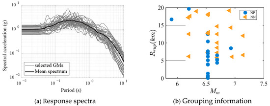
Figure 7.
Response spectra and grouping information for ground shaking records.
Figure 8 shows several selected records from the chosen dataset. As can be observed, the first and third records exhibit high intensity (with large PGA), featuring strong pulses within a short duration and significant impact characteristics, representing typical short-duration, high-intensity near-fault ground motions. In contrast, the second and fourth records demonstrate prolonged duration with relatively smooth fluctuations and evenly distributed energy, classified as long-period, moderate-to-low intensity earthquakes.
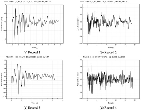
Figure 8.
Presentation of selected records from the chosen ground motion spectra.
This section establishes a high-fidelity model of the HSRTBDS. The mechanical properties of bridge and track subsystems are accurately characterized via parametric elements; dampers are integrated based on hysteresis models, coupling their nonlinear behavior with structural responses [53]; and seismic inputs encompass multiple source scenarios, establishing the foundation for subsequent quantitative seismic performance analysis.
4. Seismic Mitigation Efficacy of SSPSD in HSRTBS
4.1. Seismic Response Analysis of Critical Components
Structural safety assessment typically employs peak response quantities as key indicators for evaluating component limit exceedance. To streamline the evaluation process, this study adopts the mean transverse peak response across all seismic components as the primary metric for structural safety state assessment.
As critical supporting components, the seismic response of bearings directly impacts the safety of bridge superstructures. Figure 9a illustrates deformation in fixed bearings, where the incorporation of slitted steel plate dampers reduced peak deformation by an average of 33.90%. Table 4 presents comparative deformation data of fixed bearings after installation of SSPSDs. Maximum deformation of fixed bearings at Pier 2 position decreased from 104.48 mm to 68.66 mm—a 34.29% reduction. Figure 9b and Table 5 demonstrates even more significant improvement in movable bearings, with an average 34.12% response reduction and mean deformation of 50.56 mm, lower than the fixed bearings’ 50.81 mm. This performance differential may arise from synergistic energy dissipation: Frictional mechanisms in movable bearings work in concert with damper hysteresis to redistribute seismic energy, validating the inherent compatibility advantage of movable bearings within integrated seismic mitigation systems.
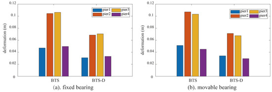
Figure 9.
The deformation of the bearings.
Table 4.
Comparison of fixed bearing deformation data.
Table 5.
Comparison of movable bearing deformation data.
Figure 10 illustrates the seismic deformation response of the main girder. As the primary load-bearing component, the girder midspan represents a structural vulnerability. After installing SSPSDs, peak deformation decreased from 120.87 mm to 102.71 mm (15% reduction). As shown in Table 6, the SSPSD reduces displacements of the main girder at all pier positions by over 16%. The dampers effectively suppressed bending vibration modes by dissipating seismic energy, demonstrating their protective function for superstructures.
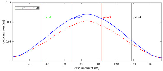
Figure 10.
The deformation of the girder.
Table 6.
Comparison of girder deformation data.
Figure 11 and Table 7 shows transverse deformation of the rail. SSPSDs reduced peak midspan deformation from 120.86 mm to 102.86 mm (14.9% reduction) while promoting more uniform deformation distribution. This indicates enhanced global bridge stiffness from the dampers, which optimizes longitudinal constraint forces and mitigates local stress concentration risks.
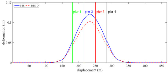
Figure 11.
The deformation of the rail.
Table 7.
Comparison of rail deformation data.
As shown in Figure 12 and Table 8, the deformation increments of the four bridge piers sequentially increased from 9.348 mm, 12.346 mm, 12.340 mm, and 9.344 mm to 13.546 mm, 22.487 mm, 22.377 mm, and 13.410 mm. The corresponding deformation increases measured 4.198 mm, 10.141 mm, 10.037 mm, and 4.066 mm, representing amplitude growth rates of 44.91%, 82.14%, 81.34%, and 43.51%, respectively, with an average increase amplitude of 62.97%. Although absolute deformations remain well below the code limit, this amplification may result from dampers enhancing the global structural stiffness, thereby redirecting seismic energy toward the piers and reducing dynamic responses in the superstructure. As depicted in Figure 13, shear key responses exhibit spatial non-uniformity: Deformations decreased at Positions 1, 3, 4, and 5 but slightly increased at Position 2. This phenomenon likely relates to localized stress redistribution induced by damper placement, necessitating further parametric optimization to balance constraint effects.
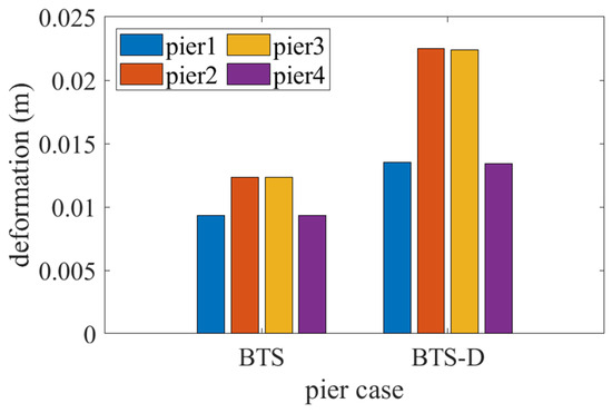
Figure 12.
The deformation of the pier.
Table 8.
Comparison of pier deformation data.
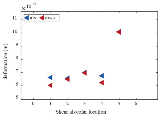
Figure 13.
The deformation of the shear alveolar.
As critical connectors between track and bridge, fastener deformation variations reflect adjustments in track-girder interaction. Figure 14 demonstrates significantly reduced peak fastener deformation in bridge sections of the HSRTBDS, while reductions at subgrade transitions remain marginal. Comparative BTS and BTS-D curves reveal substantial deformation differences (≈26.7% peak reduction) within bridge spans (100–400 m), contrasting with minimal changes (<5%) in subgrade sections (<100 m, >400 m). This spatial distribution indicates that dampers primarily suppress fastener shear demands by mitigating global bridge vibrations but exhibit limited effectiveness in optimizing local constraints at subgrade-bridge transitions. Complementary reinforcement via end anchors or restraining blocks is thus necessary for comprehensive system performance enhancement.
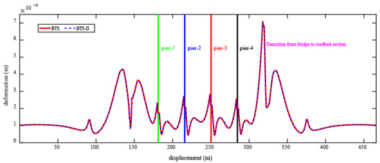
Figure 14.
The deformation of the fastener.
4.2. Comprehensive Analysis of Seismic Mitigation Effectiveness
The SSPSD significantly reduces peak deformations in fixed bearings (33.9%), movable bearings (34.12%), girders (16.63%), and track systems (16.57%), demonstrating its engineering applicability under high-intensity seismic excitations and validating its superior seismic mitigation efficacy. Although pier deformations increase by 62.97%, they remain within code limits (<30 mm), indicating that the dampers optimize seismic performance through energy redistribution, thereby preventing localized component overload. Fastener deformations decrease substantially in bridge sections (26.7% reduction) but minimally in subgrade zones (<5%), revealing the dampers’ spatially selective control mechanism over track-girder interaction.
5. Conclusions
This study addresses the seismic resilience requirements of high-speed railway track-bridge systems in high-intensity seismic zones by proposing a prefabricated multi-layer parallel-connected slit steel plate shear damper. Through theoretical derivation, numerical simulation, and integrated system analysis, its mechanical properties and seismic mitigation efficacy are comprehensively investigated. Key conclusions are summarized as follows:
- SSPSD design and performance verification. A modular prefabricated multi-layer parallel-connected slit steel plate shear damper slitted steel plate damper was designed, where energy dissipation plates achieve high-efficiency energy absorption through flexure-shear coupling deformation. Theoretical models for stiffness and load-bearing capacity were derived, demonstrating <8% error in initial stiffness prediction. Abaqus hysteresis analysis confirms stable hysteretic loops with negligible pinching at 60 mm displacement. These results satisfy the large-deformation energy dissipation demands of high-speed railway bridges. The modular design reduces replacement costs by 40%, aligning with resilient infrastructure principles.
- Track-bridge system response control mechanism. The SSPSD significantly reduces peak deformations: fixed bearings by 29.13%, movable bearings by 34.12%, girder midspan by 15%, and track systems by 14.9%. Although pier deformations increase by 62.97%, absolute values remain below code limits (<30 mm), validating the energy redistribution strategy for preventing critical component overload.
- System coupling effects and engineering applicability. By suppressing global bridge vibrations, the SSPSD optimizes track-girder interaction, markedly reducing dynamic shear demands on fasteners and track slabs. Spatial heterogeneity in shear key responses highlights the need for further optimization of damper placement parameters to balance constraint effects.
However, in this study, simplified representations were adopted for both the damper models and the HSRTBS, and the complex interactions between them were not fully captured. Future work should further investigate these limitations, with particular emphasis on the effects of parameter uncertainties and in-depth validation of the model’s behavior under varying boundary conditions.
In summary, the core mechanism of the SSPSD damper proposed in this study lies in its ability to effectively suppress the global vibrations of the bridge through additional damping. This reduction in overall vibration fundamentally improves the dynamic interaction between the upper track system and the bridge girder, thereby effectively preventing accidents such as girder derailment that could threaten operational safety. Furthermore, due to the ease of replacement of the SSPSD, it significantly reduces maintenance costs and enhances the rapid restoration capability of the high-speed railway bridge system.
Author Contributions
Conceptualization, Z.K. and L.J. (Liqiang Jiang); Methodology, F.Z. and L.R.; Software, L.J. (Liqiang Jiang); Validation, L.J. (Liqiang Jiang), Z.Z., F.Z. and L.R.; Formal analysis, Z.K. and L.Z.; Investigation, Y.H. and L.Z.; Resources, Z.K., S.T., L.J. (Lizhong Jiang), Y.H. and L.R.; Data curation, Z.Z. and L.J. (Lizhong Jiang); Writing—original draft, S.T.; Visualization, Z.Z., L.J. (Lizhong Jiang) and F.Z.; Supervision, S.T., Y.H. and L.Z. All authors have read and agreed to the published version of the manuscript.
Funding
This research was supported by the Science and Technology Research and Development Program Project of China railway group limited (2022-Major-17) and the Science and Technology Research and Development Program Project of China State Railway Group Co., Ltd. (L2023G007).
Data Availability Statement
The original contributions presented in this study are included in the article. Further inquiries can be directed to the corresponding author.
Conflicts of Interest
Authors Liqiang Jiang and Lizhong Jiang were employed by the company China Railway Group Limited. Authors Zhen Zhao, Lanzhe Rao and Lifeng Zou were employed by the company 3rd Construction Co., Ltd. of China Construction 5th Engineering Bureau. The remaining authors declare that the research was conducted in the absence of any commercial or financial relationships that could be construed as a potential conflict of interest.
Correction Statement
This article has been republished with a minor correction to the existing affiliation information and a minor correction to the Funding statement. This change does not affect the scientific content of the article.
References
- Su, M.; Dai, G.; Marx, S.; Liu, W.; Zhang, S. A Brief Review of Developments and Challenges for High-speed Rail Bridges in China and Germany. Struct. Eng. Int. 2019, 29, 160–166. [Google Scholar] [CrossRef]
- Yan, W.; Tian, X.; Wu, Z.; Ping, W.; Lin, K. Seismic response of concrete bridge of Lanzhou-Xinjiang high-speed railway under the near-fault strong earthquake. Structures 2023, 50, 1416–1428. [Google Scholar]
- Parsons, T.; Ji, C.; Kirby, E. Stress changes from the 2008 Wenchuan earthquake and increased hazard in the Sichuan basin. Nature 2008, 454, 509–510. [Google Scholar] [CrossRef]
- Sun, A.; Chen, X.; Fu, W. Improvement of seismic resilience for existing buildings based on hybrid seismic reduction technology. Shock. Vib. 2024, 43, 238–246. [Google Scholar]
- Jaehoon, B.; Huang, X.; Zhang, Z. Advanced seismic resilient performance of steel MRF equipped with viscoelastic friction dampers. Sci. Rep. 2024, 14, 19403. [Google Scholar] [CrossRef] [PubMed]
- Su, L.; Wang, Y.; Li, P.; Mei, S.; Guo, K. Seismic analysis of bridges based on stress-dependent damping. Struct. Eng. Mech. 2017, 62, 281–289. [Google Scholar] [CrossRef]
- Javanmardi, A.; Ibrahim, Z.; Ghaedi, K.; Ghadim, H.B.; Hanif, M.U. State-of-the-Art Review of Metallic Dampers: Testing, Development and Implementation. Arch. Comput. Methods Eng. 2020, 27, 455–478. [Google Scholar] [CrossRef]
- Dai, K.; He, Z.; Li, T.; Yang, Y. Mitigating ground motion duration impact on steel moment-resisting frames using viscous dampers. J. Constr. Steel Res. 2024, 213, 108430. [Google Scholar] [CrossRef]
- Xing, L.; Zhou, Y.; Zhang, P. Optimal tuned outrigger-ATMD systems considering seismic and wind loads. Soil Dyn. Earthq. Eng. 2023, 172, 108023. [Google Scholar] [CrossRef]
- Di Egidio, A.; Olivieri, C.; Contento, A.; Pagliaro, S. Improving the dynamic and seismic behaviour of rigid block-like elements through active mass dampers. Eng. Struct. 2023, 275, 115312. [Google Scholar] [CrossRef]
- Amjadian, M.; Agrawal, A.K. Feasibility study of using a semiactive electromagnetic friction damper for seismic response control of horizontally curved bridges. Struct. Control Health Monit. 2019, 26, e2333. [Google Scholar] [CrossRef]
- Zhu, X.; Jing, X.; Cheng, L. Magnetorheological fluid dampers: A review on structure design and analysis. J. Intell. Mater. Syst. Struct. 2012, 23, 839–873. [Google Scholar] [CrossRef]
- Luu, M.; Rodrigo, M.; Zabel, V.; Könke, C. Semi-active magnetorheological dampers for reducing response of high-speed railway bridges. Control Eng. Pract. 2014, 32, 147–160. [Google Scholar] [CrossRef]
- Guo, T.; Liu, J.; Zhang, Y.; Pan, S. Displacement monitoring and analysis of expansion joints of long-span steel bridges with viscous dampers. J. Bridg. Eng. 2015, 20, 04014099. [Google Scholar] [CrossRef]
- Guo, W.; Li, J.; Guan, Z. Shake table test on a long-span cable-stayed bridge with viscous dampers considering wave passage effects. J. Bridg. Eng. 2021, 26, 04020118. [Google Scholar] [CrossRef]
- Yan, X.; Alam, M.S.; Shu, G.; Qin, Y. A novel self-centering viscous damper for improving seismic resilience: Its development, experimentation, and system response. Eng. Struct. 2023, 279, 115632. [Google Scholar] [CrossRef]
- He, Z.; Shi, F.; Lin, Z.; Zhang, C.; Zhou, Y.; Zhao, F. Experimental characterization on cyclic stability behavior of a high-damping viscoelastic damper, Constr. Build. Mater. 2023, 371, 130749. [Google Scholar] [CrossRef]
- Dai, J.; Xu, Z.-D.; Gai, P.-P.; Yan, X. Seismic performance of viscoelastically damped structures at different ambient temperatures. J. Vib. Control 2020, 27, 2819–2834. [Google Scholar] [CrossRef]
- Paronesso, M.; Lignos, D.G. Experimental study of sliding friction damper with composite materials for earthquake resistant structures. Eng. Struct. 2021, 248, 113063. [Google Scholar] [CrossRef]
- Xu, G.; Ou, J. Seismic performance of combined rotational friction and flexural yielding metallic dampers. J. Build. Eng. 2022, 49, 104059. [Google Scholar] [CrossRef]
- De Matteis, G.; Brando, G.; Mazzolani, F.M. Hysteretic behaviour of bracing-type pure aluminium shear panels by experimental tests. Earthq. Eng. Struct. Dyn. 2011, 40, 1143–1162. [Google Scholar] [CrossRef]
- Xiang, N.; Alam, M.S.; Li, J. Yielding steel dampers as restraining devices to control seismic sliding of laminated rubber bearings for highway bridges: Analytical and experimental study. J. Bridg. Eng. 2019, 24, 04019103. [Google Scholar] [CrossRef]
- Briones, B.; De La Llera, J.C. Analysis, design and testing of an hourglass-shaped copper energy dissipation device. Eng. Struct. 2014, 79, 309–321. [Google Scholar] [CrossRef]
- Guo, W.; Wang, Y.; Zhai, Z.; Du, Q. Seismic control of high-speed railway bridge using S-shaped steel damping friction bearing. Smart Struct. Syst. 2022, 30, 479–500. [Google Scholar]
- Xie, X.; Chen, S.X.; Zhou, X. A simplified analytical model for U-shaped steel dampers considering horizontal bidirectional deformation. Bull. Earthq. Eng. 2018, 16, 6243–6268. [Google Scholar] [CrossRef]
- Zhai, Z.; Guo, W.; Yu, Z.; He, C.; Zeng, Z. Experimental and numerical study of S-shaped steel plate damper for seismic resilient application. Eng. Struct. 2020, 221, 111006. [Google Scholar] [CrossRef]
- Cao, X.; Shen, D.; Ji, K.; Qu, Z.; Wang, C. Recovery resilience framework of replaceable AB-BRB for seismic strengthening during the aftershock stage. ThinWalled Struct. 2024, 205, 112389. [Google Scholar] [CrossRef]
- Zhong, J.; Zheng, X.; Wu, Q.; Jiang, L.; He, M.; Dang, X. Seismic fragility and resilience assessment of bridge columns with dual-replaceable composite link beam under near-fault GMs. Structures 2023, 47, 412–424. [Google Scholar] [CrossRef]
- Fu, P.; Li, X.; Xu, L.; Wang, M. An advanced assessment framework for seismic resilience of railway continuous girder bridge with multiple spans considering 72 h golden rescue requirements. Soil. Dyn. Earthq. Eng. 2024, 177, 108370. [Google Scholar] [CrossRef]
- Andrić, J.M.; Lu, D.-G. Fuzzy methods for prediction of seismic resilience of bridges. Int. J. Disaster Risk Reduct. 2017, 22, 458–468. [Google Scholar] [CrossRef]
- Biondini, F.; Camnasio, E.; Titi, A. Seismic resilience of concrete structures under corrosion. Earthq. Eng. Struct. Dyn. 2015, 44, 2445–2466. [Google Scholar] [CrossRef]
- Yang, G.; Tian, L.; Du, Y.; Tang, G.; Ye, S.; Mao, J. Research on seismic resilience factors and improved evaluation of continuous beam bridges based on recovery function. China Civ. Eng. J. 2022, 55, 219–226. [Google Scholar]
- Xu, X.; Chen, X.; Hu, H.; Zhou, X.; Cheng, M.; Sun, L.; Li, X. Energy Dissipation and Seismic Response Reduction System for High-Speed Railway Bridges Based on Multiple Performance Requirements. Eng. Struct. 2024, 307, 117919. [Google Scholar] [CrossRef]
- Wang, X.; Liu, B.; Di Gialleonardo, E.; Kovacic, I.; Bruni, S. Application of Semi-Active Yaw Dampers for the Improvement of the Stability of High-Speed Rail Vehicles: Mathematical Models and Numerical Simulation. Veh. Syst. Dyn. 2022, 60, 2608–2635. [Google Scholar] [CrossRef]
- Liu, C.N.; Lai, S.K.; Ni, Y.Q.; Chen, L. Dynamic modelling and analysis of a physics-driven strategy for vibration control of railway vehicles. Vehicle. Syst. Dyn. 2024, 63, 1080–1110. [Google Scholar] [CrossRef]
- Alehashem, S.M.S.; Ni, Y.Q.; Liu, X.Z. A Full-Scale Experimental Investigation on Ride Comfort and Rolling Motion of High-Speed Train Equipped with MR Dampers. IEEE Access 2021, 9, 118113–118123. [Google Scholar] [CrossRef]
- Zhou, W.; Yu, J.; Jiang, L.; Lai, Z.; Zuo, Y.; Peng, K. Component Damage and Failure Sequence of Track-bridge System for High-speed Railway under Seismic Action. J. Earthq. Eng. 2023, 27, 27656–27678. [Google Scholar]
- Chen, X.; De Domenico, D.; Li, C. Seismic resilient design of rocking tall bridge piers using inerter-based systems. Eng. Struct. 2023, 281, 115819. [Google Scholar] [CrossRef]
- Chen, X., Jr.; Spencer, B.F.; Li, J.; Guan, Z.; Pang, Y. Optimization of distribution patterns of link beams in a double-column tall pier bent subjected to earthquake excitations. Earthq. Eng. Struct D 2023, 52, 52641–52659. [Google Scholar] [CrossRef]
- Kent, D.C.; Park, R. Inelastic behaviour of reinforced concrete members with cyclic loading. Bull. N. Z. Soc. Earthq. Eng. 1971, 4, 108–125. [Google Scholar] [CrossRef]
- Mander, J.B.; Priestley, M.J.N.; Park, R. Theoretical stress-strain model for confined concrete. J. Struct. Eng. 1988, 114, 1804–1826. [Google Scholar] [CrossRef]
- Popovics, S. A numerical approach to the complete stress-strain curve of concrete. Cem. Concr. Res. 1973, 3, 583–599. [Google Scholar] [CrossRef]
- Filippou, F.; Popov, E.; Bertero, V. Effects of Bond Deterioration on Hysteretic Behavior of Reinforced Concrete Joints; University of California: Berkeley, CA, USA, 1983. [Google Scholar]
- Li, S.; Wu, D. Effects of pier design on superstructure vibration. J. China Railw. Soc. 2002, 24, 73–77. [Google Scholar]
- Jiang, L.; Yu, K.; Jiang, L.; Wen, T.; Hu, Y.; Pang, L. Effects of shear panel dampers on seismic response mitigation of high-speed railway simply supported bridge-track system under far-field and near-field ground motions. Arch. Civ. Mech. Eng. 2023, 23, 93. [Google Scholar] [CrossRef]
- Yan, B.; Liu, S.; Pu, H.; Dai, G.; Cai, X. Elastic-plastic seismic response of CRTS II slab ballastless track system on high-speed railway bridges. Sci. China Technol. Sci. 2017, 60, 865–871. [Google Scholar] [CrossRef]
- Hibbit, D.; Karlsson, B.; Sorensen, P. ABAQUS/Standard Analysis User’s Manual, version 6.13; Dassault Systèmes/Simulia: Providence, RI, USA, 2013.
- Khalili, M.; Sivandi-Pour, A.; Noroozinejad Farsangi, E. Experimental and numerical investigations of a new hysteretic damper for seismic resilient steel moment connections. J. Build. Eng. 2021, 43, 102811. [Google Scholar] [CrossRef]
- Zahrai, S.M.; Motezagholi, M.H. Cyclic Performance of an Elliptical-Shaped Damper with Shear Diaphragms in Chevron Braced Steel Frames. J. Earthq. Eng. 2018, 22, 1209–1232. [Google Scholar] [CrossRef]
- Jiang, L.; Liu, X.; Yan, Y.; Jiang, L. U-shape energy-dissipation device for enhancing seismic resilience of high-speed railway track-bridge systems. J. Constr. Steel Res. 2024, 226, 109257. [Google Scholar] [CrossRef]
- Mou, B.; Wang, Z.; Zhang, Z.; Wu, C. Seismic behavior of steel frames with H-shaped damper. J. Constr. Steel Res. 2024, 213, 108401. [Google Scholar] [CrossRef]
- Jiang, L.; Yan, Y.; Wen, T.; Jiang, L.; Yu, K.; Pang, L. System-level seismic fragility of high-speed railway track-bridge system with component-replaceable U-shaped combined steel damper. Structures 2023, 58, 105452. [Google Scholar] [CrossRef]
- Yang, Y.; Liu, C.; Lai, S.-K.; Chen, Z.; Chen, L. Frequency-dependent equivalent impedance analysis for optimizing vehicle inertial suspensions. Nonlinear Dyn. 2025, 113, 9373–9398. [Google Scholar] [CrossRef]


Disclaimer/Publisher’s Note: The statements, opinions and data contained in all publications are solely those of the individual author(s) and contributor(s) and not of MDPI and/or the editor(s). MDPI and/or the editor(s) disclaim responsibility for any injury to people or property resulting from any ideas, methods, instructions or products referred to in the content. |
© 2025 by the authors. Licensee MDPI, Basel, Switzerland. This article is an open access article distributed under the terms and conditions of the Creative Commons Attribution (CC BY) license (https://creativecommons.org/licenses/by/4.0/).