Article

Design Simulation and Applied Research of a New Disc Spring-Laminated Rubber Dissipating Device Used in Corrugated Steel Plate Shear Walls

School of Civil Engineering, Chang’an University, Xi’an 710061, China
*
Author to whom correspondence should be addressed.
Buildings 2025, 15(16), 2903; https://doi.org/10.3390/buildings15162903 (registering DOI)
Submission received: 24 June 2025 / Revised: 3 August 2025 / Accepted: 9 August 2025 / Published: 16 August 2025
(This article belongs to the Special Issue Damping Control of Building Structures and Bridge Structures)

Abstract

Addressing the issue of stress concentration at the toe of steel plate shear walls, which is susceptible to local buckling and brittle failure under seismic loading, this paper innovatively proposes a disc spring-laminated rubber energy dissipation device (DSLRDD) newly designed for application at the wall toe of the shear wall structures. Firstly, the structure characteristics and energy dissipation principle of the DSLRDD are described. Secondly, the finite element model of the DSLRDD is established in ABAQUS. Furthermore, the optimal design parameters’ values of DSLRDD are analyzed and given by taking the stacking arrangement of disc springs, the thickness ratio of steel plate to rubber layer, and the yield strength of steel plate as three main parameters. It is recommended that in DSLRDD, the disc spring stacking arrangement adopts either two pieces in series or a composite of series–parallel. At the same time, the range of the thickness ratio between the steel plate and the rubber layer is defined as being between 1.25 and 2.5, and the yield strength value of the steel plate is determined as 400 MPa. Finally, to verify the energy dissipation capacity of the DSLRDD, a double corrugated steel plate shear wall (DCSPSW) is taken as the experimental structure. The model has been verified against the test data, with a maximum damping force error of 14.4%, ensuring reliable modeling. DSLRDD models with the disc spring stacking arrangements of two pieces in series and composite of series–parallel were established, respectively, and they were installed at the toe of the DCSPSW. The seismic performance of the DCSPSW before and after the installation of two different DSLRDDs is studied. The results show that the DSLRDDs have obvious energy absorption capabilities. The energy dissipation factors of DCSPSW before and after installing DSLRDD were increased by 10.0% and 8.9%, respectively. DCSPSW with DSLRDD exhibits better plasticity and bearing capacity under seismic action, and the stress and deformation are mainly concentrated on the DSLRDD instead of the wall toe. Moreover, it is recommended to use the stacking arrangement of two series disc springs with a simple structure. In conclusion, the DSLRDD has excellent energy dissipation capacity and can be fully applied to practical projects.

1. Introduction

Steel plate shear walls are widely used in high-rise buildings, thanks to their good lateral resistance and economy [1]. Compared with the traditional flat steel plate shear wall, the corrugated steel plate shear wall utilizes the “accordion effect” [2], which can effectively improve the ductility and deformation capacity of the steel plate shear wall [3,4].
As of now, scholars have carried out a lot of research on the mechanical properties of corrugated steel plate shear walls. Zhao, Li et al. [5,6,7] analyzed the elastic buckling and nonlinear thrust properties of single-layer corrugated steel plate shear wall with ABAQUS and found that compared with flat steel plate shear wall, corrugated steel plate shear wall showed higher elastic buckling critical load and vertical load resistance. Tong et al. [8] carried out low-cycle repeated tests on four double-corrugated steel plate shear walls, and the results showed that the double-corrugated steel plate shear walls had good energy dissipation capacity. Du et al. [9] established finite element models of single-waveform and double-waveform steel plate shear walls, respectively, using the finite element method in ABAQUS, and comparatively analyzed the mechanical mechanisms and hysteretic performances of the two types of steel plate shear walls under low-cycle reciprocating loads. The study indicated that, compared with the single-waveform steel plate shear wall, the lateral stiffness, bearing capacity, and energy dissipation capacity of the double-waveform steel plate shear wall were all improved, but its ductility was reduced to some extent.
However, under the action of earthquakes, plastic strain is easy to accumulate at the toe of the steel plate shear wall. At present, there are two main ways to solve this type of problem. One is to repair the toe part of the steel plate shear wall damaged after the earthquake; the other is to design the original shear wall toe as a replaceable member [10]. The idea of “replaceable” was first applied to bridge engineering in structural engineering before being extended into the steel structure system [11]. A structural system with replaceable components refers to a special structural system in which replaceable members are arranged at the appropriate part of the shear wall structure, and the seismic energy is dissipated through the concentrated plastic deformation of the components.
Ozaki et al. [12,13] proposed a replaceable damper applied to the toe of a rocking steel plate shear wall. The damper consists of a pair of butterfly-shaped steel plates and U-shaped steel and mainly dissipates energy through the yielding of the butterfly-shaped steel plates. Du et al. [14] proposed a novel rocking double-corrugated steel plate shear wall system with replaceable dampers. The damper is composed of a buckling-restrained cover plate, a sleeve, and a diamond-shaped perforated steel plate. It mainly dissipates energy through the yielding of the diamond-shaped perforated steel plate. Finite element analysis shows that this new type of rocking steel plate shear wall structure has superior seismic performance. Wang et al. [15] developed a replaceable metallic damper for shear wall toes, which uses corrugated steel plates as energy dissipation components. Quasi-static tests were conducted to evaluate the influence of different structural dimensions on the mechanical properties of the damper, and the applicability of the model was verified. The aforementioned dampers all use metal in their energy-dissipating components. Despite their excellent energy-dissipating capacity, they lack some self-centering capability. Lu et al. [16] and Mao et al. [17] developed a new type of shear wall system with replaceable foot parts, using rubber and mild steel as main energy-dissipating elements. Quasi-static tests indicate that the shear wall with such parts exhibits a certain reduction in bearing capacity. Liu et al. [18,19] proposed a novel shear wall system with replaceable foot parts, which combines the stress characteristics of reinforced concrete tubes and buckling restrained brace, and which has good seismic performance. Zhu et al. [20] proposed a self-centering vertical tooth swing shear wall. In this system, the mild steel dampers dissipate the energy, the vertical disc spring resetting devices on both sides provide the resetting bending moment, and the vertical tooth rocking supports function in force transfer and fixing. However, the composition of these devices is relatively complex, making them challenging to apply in reality.
Currently, there are only a few relevant studies on energy dissipation devices at the toe of the steel plate shear wall. There is an urgent need to construct more device models to fill this research gap. Therefore, this paper combines the advantages of disc springs and laminated rubbers and innovatively proposes a disc spring-laminated rubber energy dissipation device which combines the merits of replaceability, simple configuration, and superior energy-dissipating capacity while exhibiting a certain degree of self-centering capability. Finally, DSLRDD models with the disc spring stacking arrangements of two pieces in series and a composite of series–parallel were established, respectively. They were added to the toe of the DCSPSW with the optimal values of design parameters, and the energy dissipation capacities of the DCSPSW before and after the installation of the DSLRDD were studied too.

2. Design of DSLRDD

2.1. Configuration of DSLRDD

As shown in Figure 1, the DSLRDD is mainly composed of five parts, including the intermediate disc spring, laminated rubber, bolt, steel frame, and restraining steel plate. The top of the disc spring is fixed by a disc spring baffle to limit the displacement of the upper part, and the bolt cap is bolted to the ground anchor to fix the disc spring. The laminated rubber is made by stacking thin steel plates and natural rubber layers together, and it has a very high vertical stiffness, which can ensure its stability during large deformations [21,22]. The purpose of arranging the laminated rubber on both sides of the disc spring is to ensure that the laminated rubber can be subject to uniform stress when the wall toe is compressed. The two sides of the laminated rubber are provided with restraining steel plates, and their purpose is to inhibit the transverse deformation of the rubber and ensure the normal operation of the disc spring. At the same time, to avoid mutual interference between the laminated rubber and the disc spring during the deformation process, a 10 mm deformation gap is reserved between the restraining steel plate and the disc spring.

2.2. Mechanism of the DSLRDD

Under the action of earthquake, the DSLRDD installed at the toe of the wall effectively absorbs and dissipates the seismic energy through plastic deformation, to ensure that the main body is protected from serious damage.
The specific force is described as follows: Under the action of the main structure, when one side of the wall toe is compressed, the laminated rubber and the wall toe are compressed together to reduce the force and deformation at the position of the wall toe. At the same time, the toes on the other side of the wall are pulled, and the disc springs are compressed and deformed, thereby consuming energy.

2.3. Dimension of the DSLRDD

The total dimensions of the device are designed as 400 mm long, 300 mm wide, and 260 mm high. The central disc spring assembly is chosen to be made up of 12 individual disc springs stacked in pairs (each with a height of 13.5 mm, a thickness of 10 mm, and a diameter of 160 mm), and the disc spring baffle size is defined as 150 × 150 × 10 mm. The width of the natural rubber layer and the thin steel layer are both fixed at 100 mm, and the thickness is fixed at 5 mm and 3 mm, respectively. The thickness of the restraining steel plate is defined as 5 mm, the diameter of the ground anchor bolt is fixed at 40 mm, the top and bottom plates of the steel frame are designed to be 30 mm in size, and the gap between the top of the ground anchor bolt and the restraining steel frame is set at 10 mm.

3. Finite Element Model of the DSLRDD

3.1. Establishment of DSLRDD FEM

3.1.1. Material Properties

Rubber has the properties of softness and high ductility, and it is often defined as a viscoelastic or hyperplastic material. This paper uses the properties of rubber materials from the article of Yang [23], and the parameters of the Yeoh model for rubber materials are shown in Table 1.
The material properties of the disc spring are 60Si2MnA, and the elastoplastic model is used in ABAQUS. The elastic modulus of the material is 206,000 MPa, the Poisson’s ratio is 0.3, and the yield strength is 1600 Mpa [24].
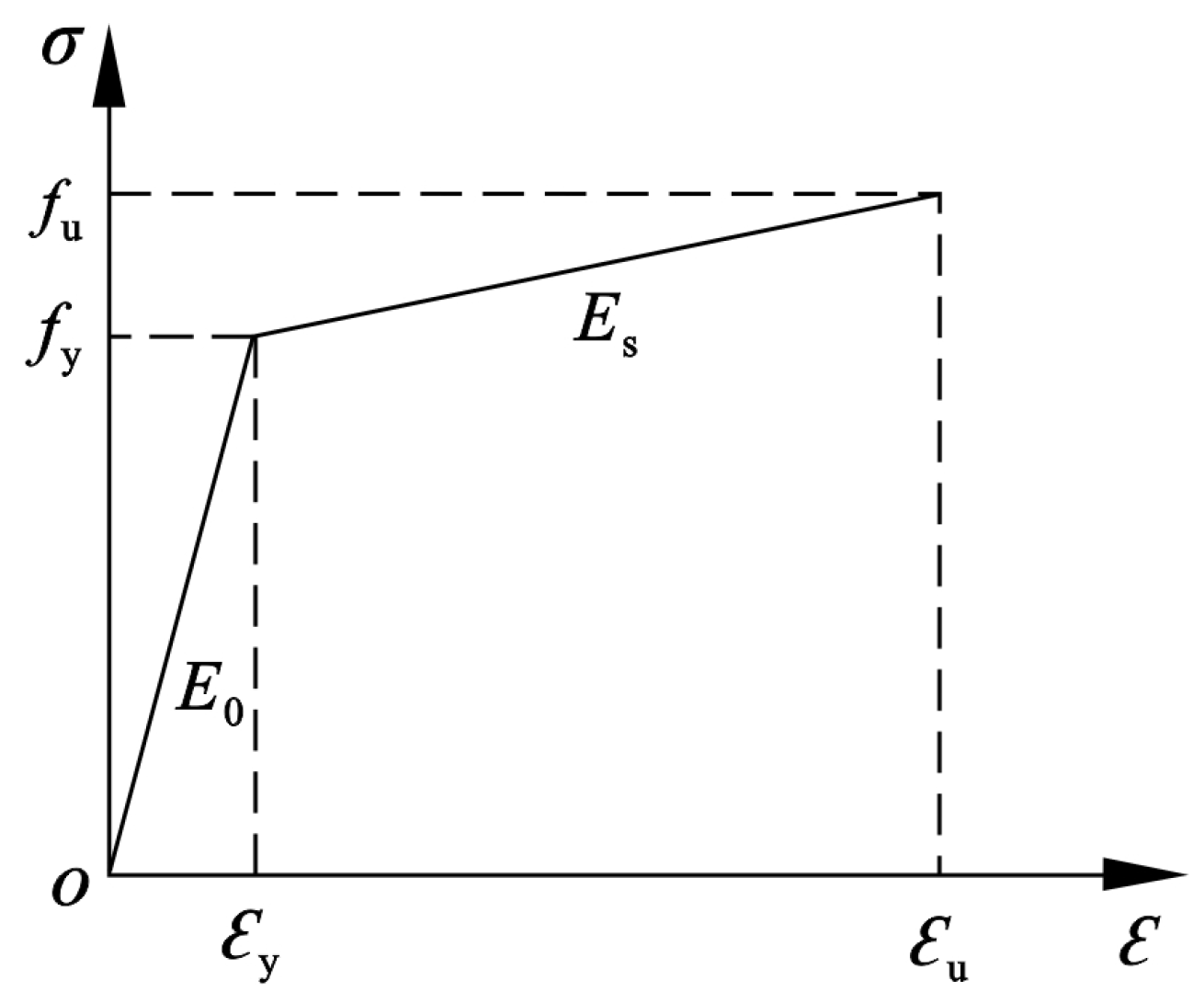
The steel plates are all ordinary carbon steels, and the elastic modulus and Poisson’s ratio of the materials are E 0 = 206 Gpa and u = 0.3, respectively. The constitutive relationship of the steel is bilinear ideal elastic–plastic model, and the hardening stiffness follows the rules of E S = 0.01 E 0 . The constitutive relation of steel is as shown in Figure 2.

3.1.2. Element and Mesh Division

Considering the homogeneity of the materials, the model uses C3D8R elements [25]. The mesh division method is sweep, and the medial axis is selected. Considering the finite element calculation time based on mesh sensitivity, after multiple trial calculations, the mesh size of the disc spring and laminated rubber is determined to be 5 mm, and the mesh size of other components is 15 mm.

3.1.3. Contacts and Loading Regimes

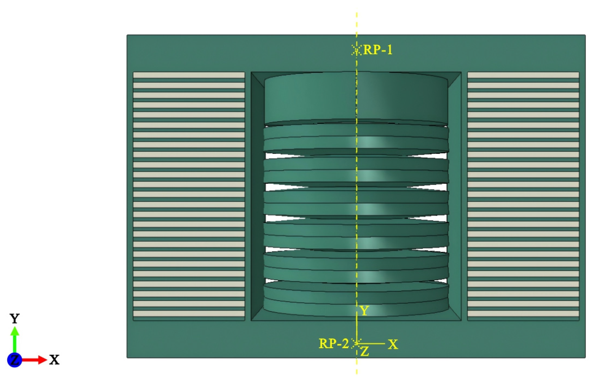
The specific connection between the ground anchor bolt and the disc spring baffle is not the main influencing factor for the follow-up research, so the connection between the ground anchor bolt and the disc spring baffle is simplified as a whole. Binding constraints are used between the laminated rubber and the steel frame. The contact action between the disc spring and the screw is adopted. The contact properties are fixed as follows: the normal contact is a “hard” contact, the penalty function is used for tangential contact, and the coefficient of friction is 0.5. Finally, a finite element model is established, as shown in Figure 3.
The force-bearing mode of the DSLRDD in the structure is described as follows: under compression, the steel plate and the rubber layer share the load; under tension, the screw compresses the disc spring to carry the load. Therefore, two loading methods are carried out for different force modes—one is when the steel plate and rubber layer are fixed as two variables, and the pressure is applied at the top of DSLRDD; the other is when the disc spring parameters are changed, and a tensile force is applied to the screw.

3.2. Calibration of FEM with Lab Data

To verify the accuracy of the constitutive parameters and the finite element simulation in this paper, the simulated results are compared with the uniaxial compression test data of the composite rubber layer conducted by Zhang et al. [26] and the uniaxial compression test data of the monolithic disc spring performed by Gao [24] using the aforementioned material properties. The comparative results are shown as follows.
It can be observed from Figure 4 and Figure 5 that the curves obtained from the ABAQUS model have a high degree of overlap with those from the experiment, which indicates that the modeling method adopted in this paper is reliable and can ensure the correctness of the finite element simulation analysis of DSLRDD.

4. Parameter Analysis for DSLRDD

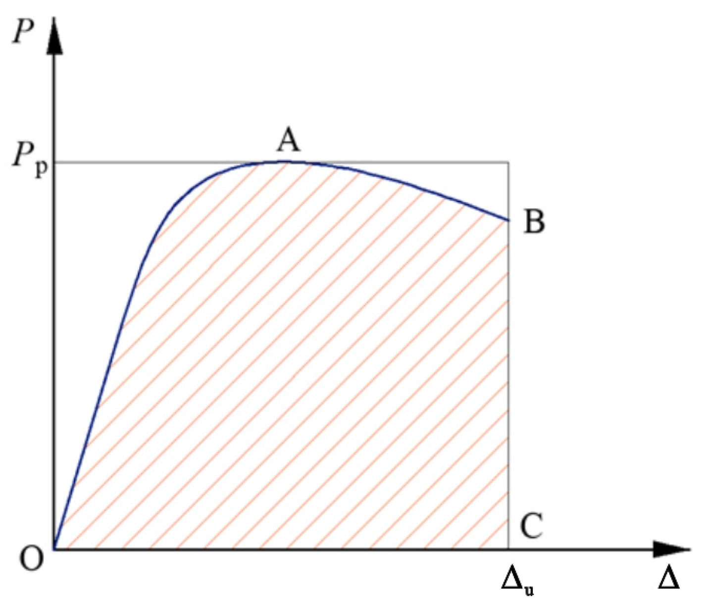
Since the main energy-consuming components of the DSLRDD are the disc springs and laminated rubber, this paper designs 16 DSLRDDs with 3 varying parameters—the stacking arrangement of the disc springs, the thickness ratio of the steel plate thickness t s to the rubber layer thickness t r , and the yield strength of the steel plate f y . It also establishes corresponding finite element models for simulation calculations, focusing on analyzing the stress nephograms, load–displacement curves, ductility coefficients, and energy consumption factors under loading conditions. The method for calculating the ductility coefficient is the equal energy method, calculated according to Equation (1) [27]. The energy dissipation factor is calculated according to Equation (2), and the calculation model of the energy dissipation factor is shown in Figure 6. Equations (1) and (2) are as follows:
μ = Δ u / Δ y
h e = S OABC / P p Δ u
where Δ y is the yield displacement, and Δ u is the displacement when the load is reduced to 85% of the ultimate load [28], S OABC is the area enclosed by the compression curve and the x-axis, shown in Figure 6, and P p is the peak load. Since the load is not reduced in the subsequent analysis, the compression curve of the rubber layer was uniformly taken at 4 mm, and the compression curve of the disc spring was taken at 10 mm.

4.1. Effect of the Stacking Arrangement of Disc Springs

In this paper, three stacking arrangements of disc springs are designed to study their effects on the performance of DSLRDD, and the testing values of parameters are shown in Table 2. The specimen number of this category is named F, and the calculated ductility coefficient and energy dissipation factor are put into the table for facilitating the observation.
Table 2. Parameters of F-series specimens.
Specimen NumberStacking Arrangementts/mmtr/mmts/trfy/MPauhe
F-AA350.604003.170.80
F-BB350.604002.280.45
F-CC350.604001.940.75
Note: A, B, and C represent three types of disc spring stacking arrangements, as shown in Figure 7.
Figure 7. The stacking arrangements of the disc springs: (a) Multiple pieces in parallel (arrangement A); (b) two pieces in series (arrangement B); (c) composite series–parallel (arrangement C).
Buildings 15 02903 g007

4.1.1. Stress Nephogram

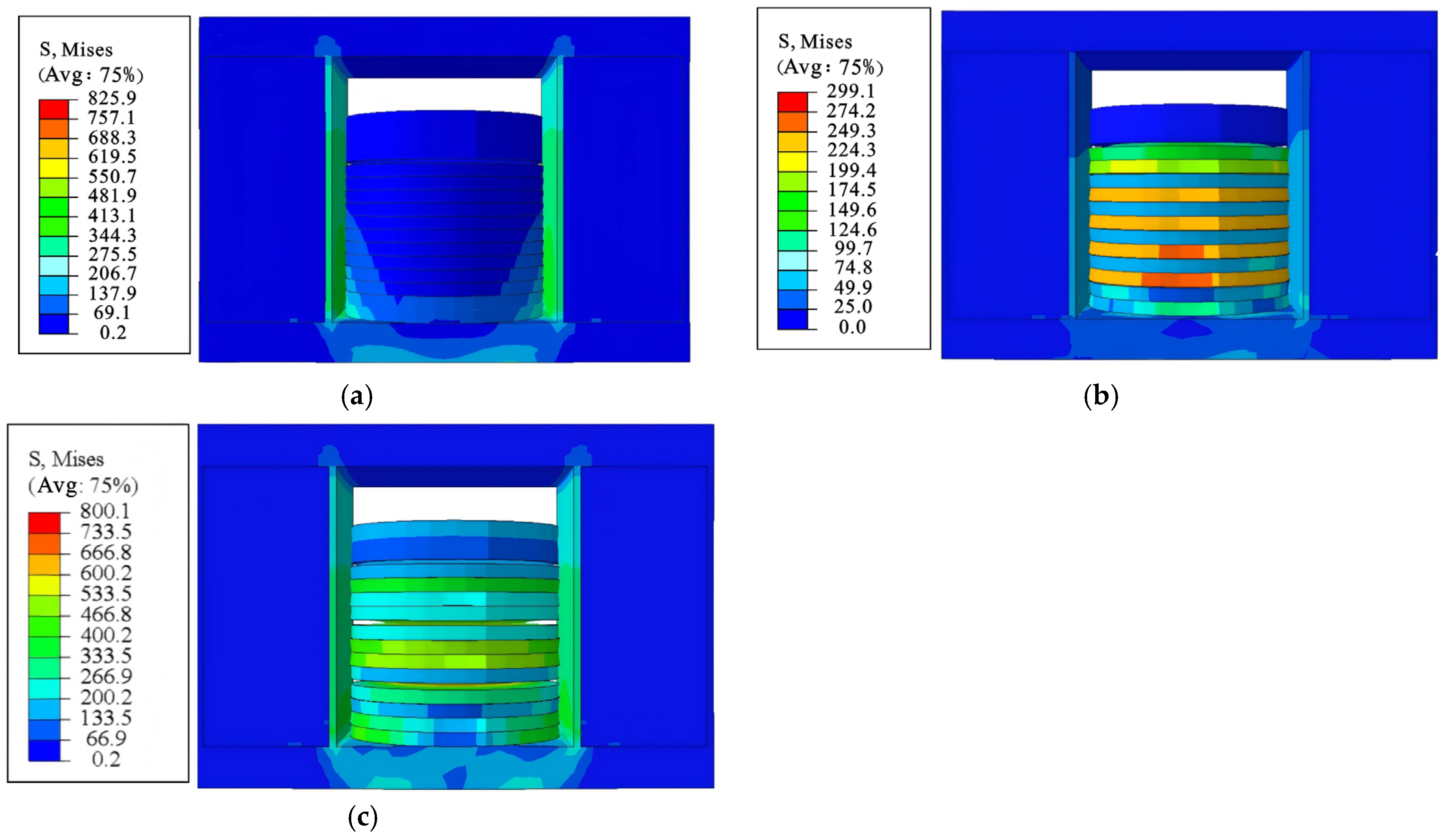
In order to facilitate comparative study, the stress nephograms of the DSLRDD at the moment when the vertical displacement reaches 10 mm are analyzed, as shown in Figure 8. As can be seen from the figures, compared with the other two arrangements, stacking arrangement A does not have obvious stress concentration, the deformation is the smallest, and the main occurrence is the yield elongation of the screw, which shows the poorest deformation ability. In stacking arrangement B, the main deformation of the disc spring occurs, and the screw rod does not undergo obvious deformation, showing good energy dissipation capacity. In stacking arrangement C, the disc spring shows a relatively obvious uniform distribution of stress, accompanied by the yield elongation of the screw. In summary, the deformation ability of stacking arrangements B and C is better than that of stacking arrangement A, while stacking arrangement B is the best.

4.1.2. Load–Displacement Curves

The load–displacement curves of the specimens are shown in Figure 9. It can be observed that although stacking arrangement A has a large stiffness, its curve inflection point is obvious, which means that it is not suitable for performing energy dissipation when it is used as an energy-dissipating member. However, the load–displacement curves of stacking arrangements B and C do not have obvious curve inflection points and show good deformation space. Combined with the stress nephograms, it can be seen that stacking arrangements B and C will enhance the deformation capacity of the DSLRDD and improve its energy dissipation capacity.

4.1.3. Ductility Coefficient and Energy Dissipation Factor

According to Formula (1), the ductility coefficients of stacking arrangements A, B, and C are calculated as 3.17, 2.28, and 1.94, respectively. It can be seen that stacking arrangement A has the highest ductility coefficient, but it is not recommended to be chosen because of its poor deformation ability, mainly due to the yield failure of the screw. Under the same vertical displacement, the energy dissipation factor of the disc spring in stacking arrangement A is the largest at 0.80, followed by stacking arrangement C at 0.75, while that of stacking arrangement B is the smallest at 0.45. This is due to the fact that stacking arrangements B and C demonstrate better adaptability and deformation capability compared to stacking arrangement A, which absorbs and dissipates relatively less energy. Therefore, from the perspective of deformation and ductility, it is recommended that the DSLRDD should use stacking arrangements B and C.

4.2. Effect of the Thickness Ratio of the Steel Plate to Rubber Layer

To study the effect of the thickness ratio of the steel plate to the rubber layer (hereinafter referred to as the “layer thickness ratio”) on the performance of the DSLRDD, when the disc spring is in stacking arrangement B and the yield strength of the steel plate is 400 MPa, only the thickness of the steel plate and the thickness of the rubber layer were adjusted. The total group of this specimen type is named with R, and the calculated ductility coefficient and energy dissipation factor are shown in Table 3.

4.2.1. Stress Nephogram

The stress nephograms of DSLRDDs with different layer thickness ratios when the vertical displacement reaches 4 mm are shown in Figure 10. As can be seen from the figures, the stress nephograms for specimens with different layer thicknesses ratios are basically similar, and the stress is primarily concentrated on the constraining steel plates, as these plates directly bear the vertical load. When the proportion of the rubber layer’s thickness is relatively large, the constraint steel plate is prone to buckling instability, but as the proportion of the steel plate’s thickness becomes larger, the buckling is not significant.

4.2.2. Load–Displacement Curves

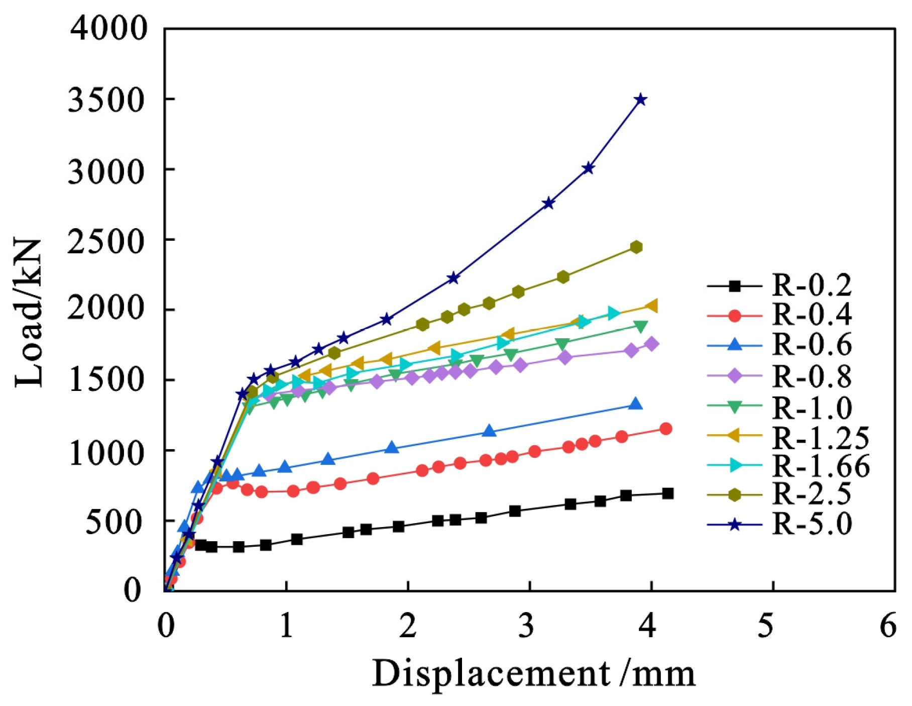
The load–displacement curves of specimens with different layer thickness ratios are shown in Figure 11. For convenience of observation, the load-displacement–displacement curve is divided into two groups. As can be seen from the figure, the load–displacement curves of the DSLRDD under axial compression are basically similar. The initial stiffness seems to be mainly provided by the constraining steel plate, because changing the thickness of the steel plate layer has little effect on the slope of the elastic segment. When the constraint steel plate enters the plastic segment, the steel plate layer starts to function, which is supported by the following observations: with the increase in the thickness of the steel plate layer, the stiffness of the energy dissipation device increases, and the slope of the plastic segment increases significantly. Although thicker steel plates can enhance the overall strength of the DSLRDD to a certain extent, increasing the thickness of the steel plates excessively will weaken the cushioning effect of the rubber. On the contrary, if the proportion of the rubber layer thickness increases, the stiffness of the DSLRDD will decrease, which leads to further problems, such as insufficient bearing capacity and yield strength. To summarize, it is recommended that the value range of the layer thickness ratio is properly proposed as 1.25~2.5.

4.2.3. Ductility Coefficient and Energy Dissipation Factor

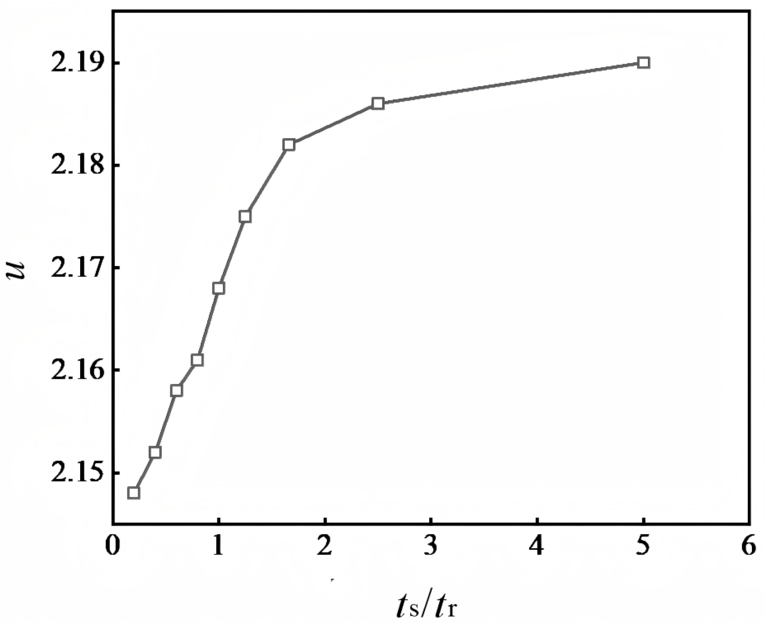
In Figure 12, It can be seen that the ductility of the DSLRDD shows a trend of rapid growth first and then slows down with the increase in the thickness ratio of steel plate to rubber layer, resulting from the mechanism of rubber and steel plate in the process of transfer of support stiffness control. The ductility coefficient grows rapidly when the thickness ratio is between 0.2 and 1.25, grows slowly for a ratio of 1.25~2.5, and is nearly stable when the ratio is more than 2.5.
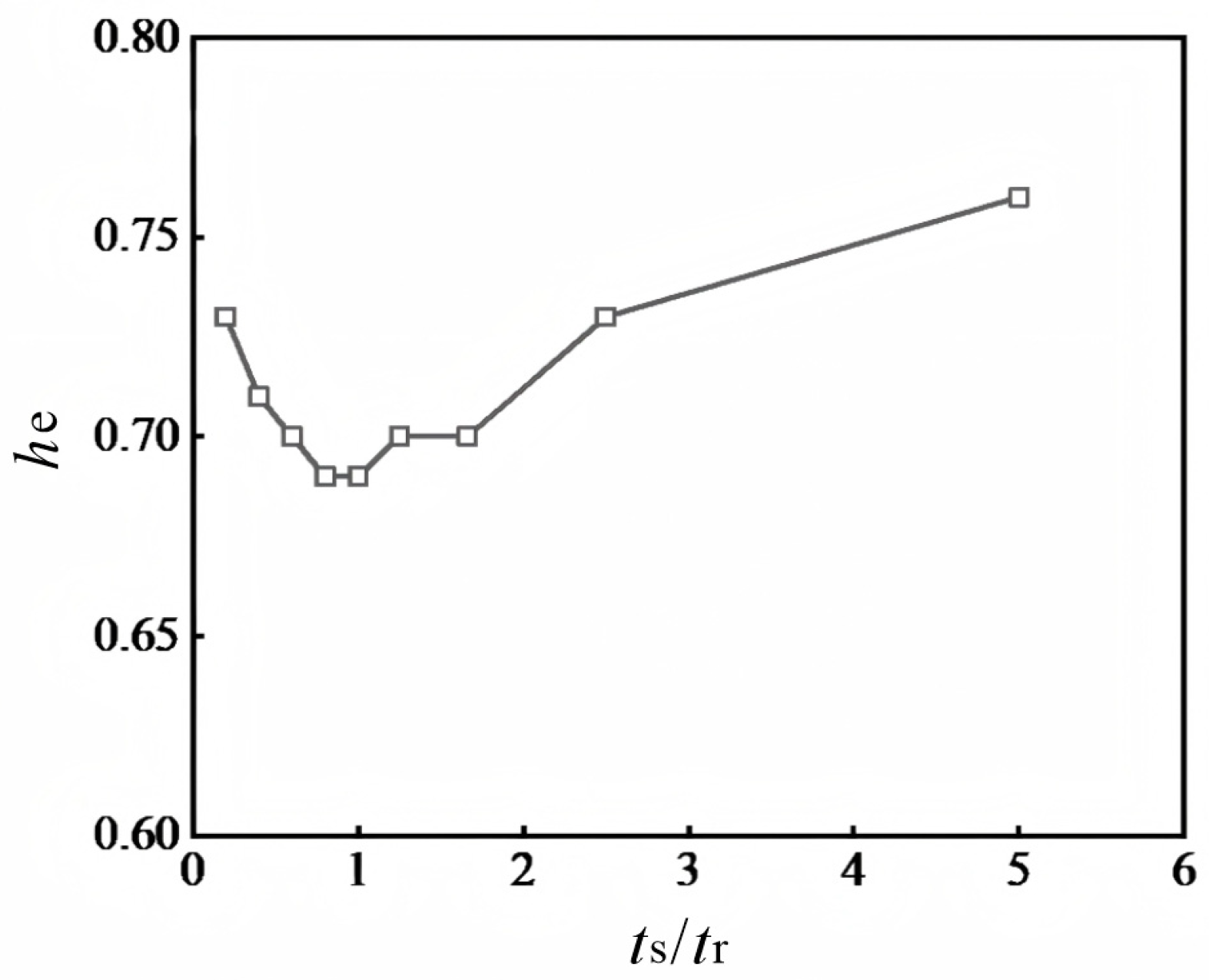
The variation curves of energy dissipation factors of specimens with different layer thickness ratios are shown in Figure 13. With the increase in the layer thickness ratio, the energy dissipation factor of the DSLRDD first decreases and then increases; when the layer thickness ratio is about 0.8~1.0, the energy dissipation factor is the lowest, and then the energy dissipation factor gradually increases, but only when the thickness ratio is above 2.5 does it show positive growth. This is related to the principle that the increase in the thickness of the steel plate will lead to an increase in the overall stiffness of the DSLRDD. A DSLRDD with greater stiffness will produce a smaller deformation, so that the energy dissipation factor is smaller. However, as the layer thickness ratio continues to increase, the elastic deformation is gradually saturated, and the steel plate begins to enter the plastic deformation stage. At this time, the stiffness of the DSLRDD is relatively small, allowing it to better absorb and dissipate energy, so that the energy dissipation factor increases, while the thickness of the steel plate will also limit the deformation ability of the rubber. Therefore, the stiffness and ductility of the DSLRDD should be comprehensively considered when selecting the layer thickness ratio, and the value range of the layer thickness ratio is recommended to be 1.25~2.5.

4.3. Effect of the Yield Strength of the Steel Plate

In order to study the effect of the yield strength of steel plates on the DSLRDD, four kinds of specimens with different yield strengths of steel plates were designed and tested, with stacking arrangement B of disc springs and the total number of these specimens named with S. As above, for ease of observation, the calculated ductility coefficient and energy dissipation factor are shown in Table 4.

4.3.1. Stress Nephogram

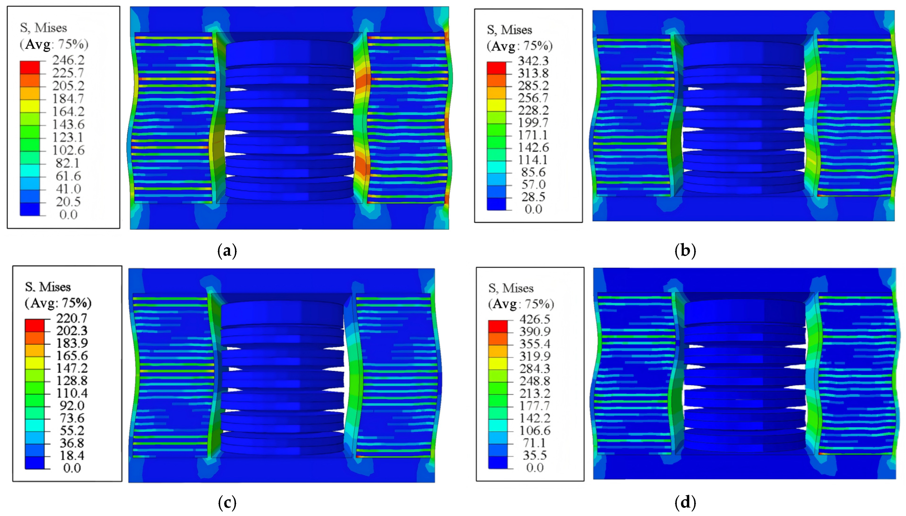
The stress nephograms of the DSLRDD with different yield strengths of steel plates reaching 4 mm in vertical displacement are shown in Figure 14. As can be seen from the figures, the stress nephograms of specimens with different yield strengths of steel plates are basically similar, indicating that the yield strength of steel plates has little impact on the stress distribution of the DSLRDD under axial compression.

4.3.2. Load–Displacement Curves

The load–displacement curves of different steel plate yield strength specimens are shown as follows in Figure 15. It can be seen from the figure that with the increase in the yield strength of the steel plate, the strength of the DSLRDD gradually increases, but the tendencies basically match in both elastic section and the plastic section, and the strengthening section shows an increasing trend. The main reason is that the higher strength steel plate is capable to withstand greater axial compressive loads without producing the plastic deformation. Therefore, the high strength of the steel plate allows the DSLRDD to maintain high stiffness and strength under load.

4.3.3. Ductility Coefficient and Energy Dissipation Factor

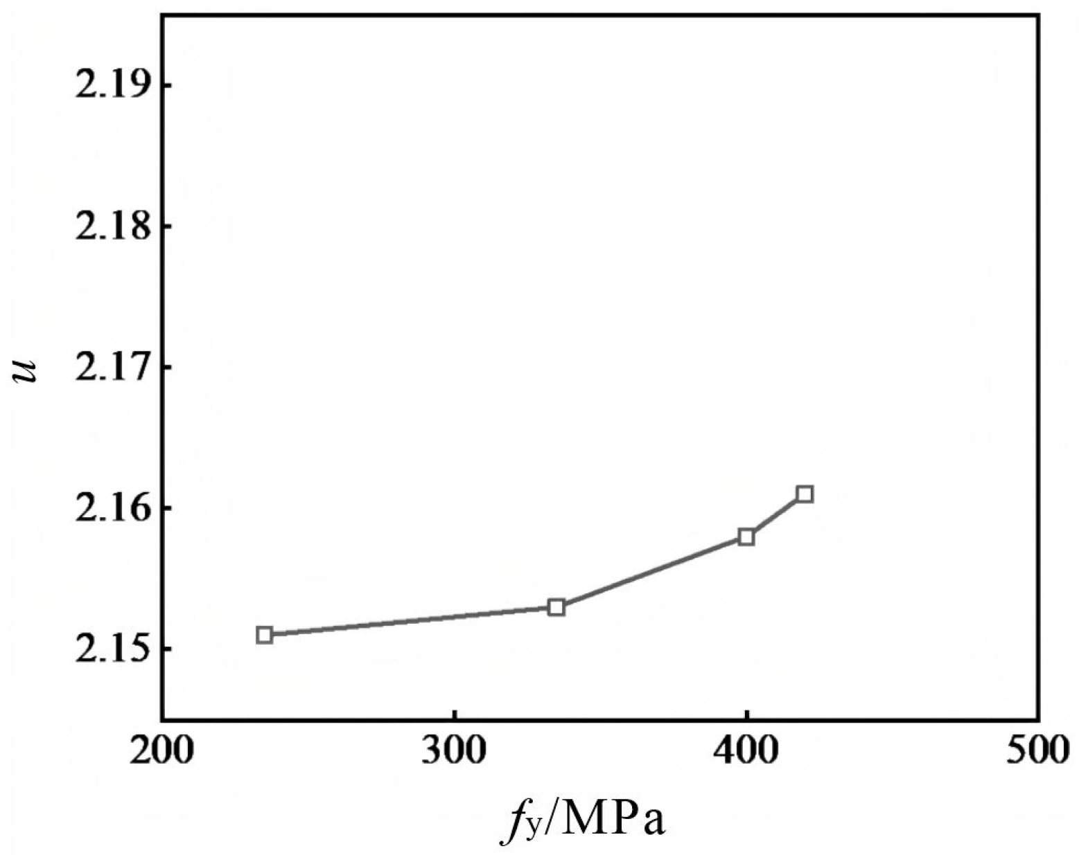
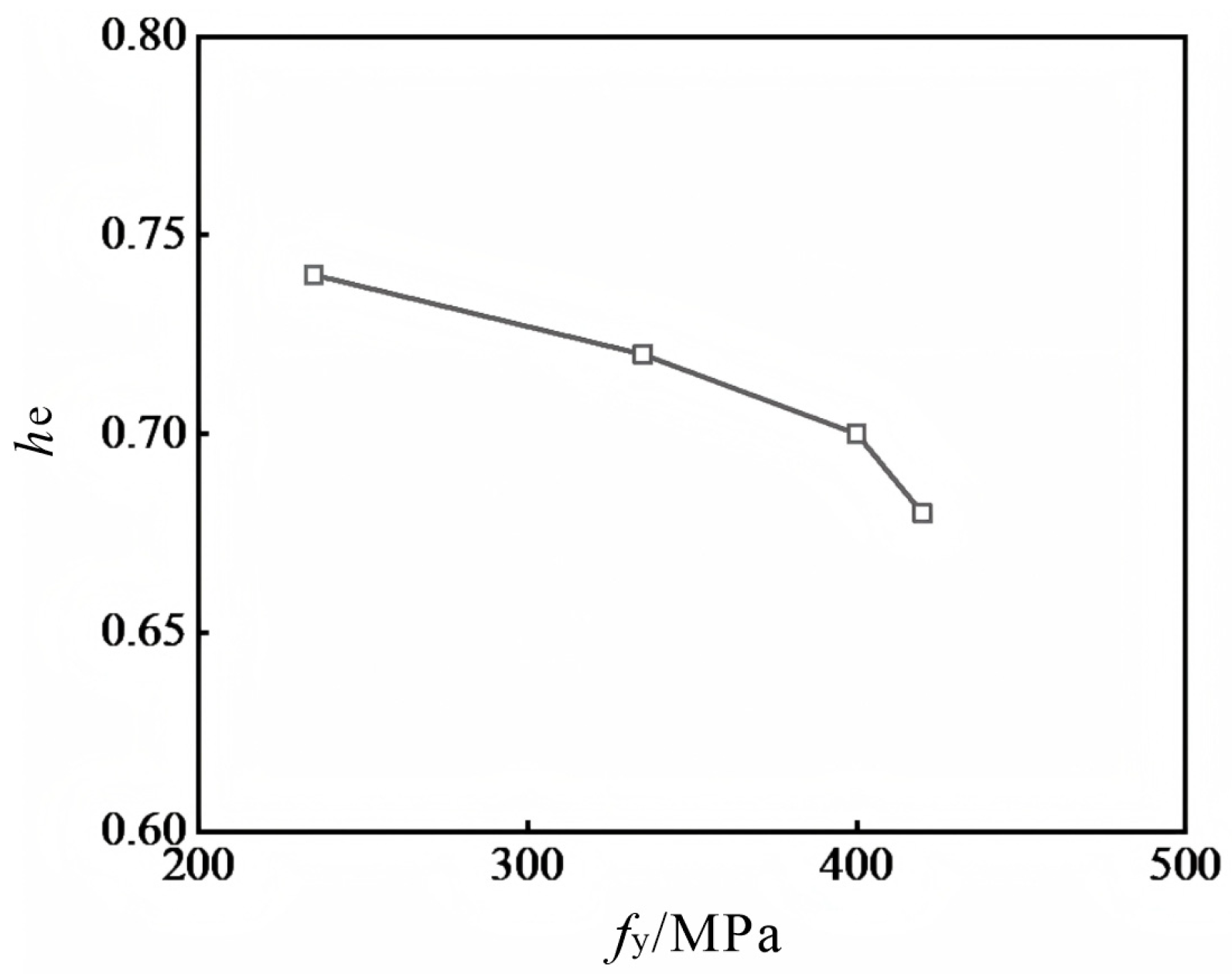
Variation curves of ductility coefficients for specimens of different steel plate yield strengths are shown in Figure 16. Compared with the specimen with a yield strength of 235 MPa, the ductility coefficients of the yield strength of the ones with 335 MPa, 400 MPa, and 420 MPa increased by 0.09%, 0.32%, and 0.46%, respectively, because the higher the yield strength, the greater the stiffness. Therefore, it is recommended to select a steel plate with high yield strength to ensure that the DSLRDD has sufficient stiffness. Meanwhile, the variation curves of the energy dissipation factor for specimens with different yield strengths of steel plates are shown in Figure 17. Compared to the specimen with a yield strength of 235 MPa, the reduction rates for steel plates with yield strengths of 335 MPa, 400 MPa, and 420 MPa are 2.8%, 5.4%, and 8.2%, respectively. When the stiffness of the steel plate increases, the stiffness of the DSLRDD increases, resulting in a decrease in the overall deformation of the structure, thereby reducing the energy dissipation factor. Therefore, the yield strength of the steel plate should not be too high, with a recommended value of 400 MPa.

5. Simulation Test of DSLRDD Performance

5.1. General Information of a Study Case

On the basis of the existing research, the corrugation parameters of the optimal double corrugated steel plate shear wall (DCSPSW) are selected because of its better mechanic performance. The DCSPSW’s dimensions are shown in Figure 18, and the thickness of the corrugated plate is fixed at 6 mm. The edge restraining components of the DCSPSW are made of H-shaped steel, and the material is Q345 steel. The specific dimensions refer to the previous reference [8]. To verify the correctness of the modeling of the DCSPSW, the DCPSW-H2 specimen in the literature is selected for modeling, as shown in Figure 19. Overall, the load–displacement angle (δ) curve obtained from the finite element analysis shows a good agreement with the test results. The maximum damping force of the damper differs by 14.4%, which is less than 15%. The primary reason for the slight discrepancy is that there are gaps in the original test setup, and neither the loading device nor the fixing device is completely rigid, resulting in a slightly smaller hysteresis loop. It is important to note that when modeling DCPSW-H2, shell elements were selected and the effects of the initial defects were considered using the first-order buckling mode, where the initial defect size is set to H/750 [29]. In addition, the overall loading system adopts a displacement-controlled loading system. To sum up, the DSLRDD specimens with stacking arrangements B and C were selected in this section study, both having the thickness ratio of the steel plate to the rubber layer of 1.25 and a steel plate yield strength of 400 MPa. They were designated as M1 and M2, respectively. In order to adapt to the DCSPSW model size scale, the DSLRDD mentioned above was scaled down by 1/4, and the model was established as shown in Figure 20.
To loosen the vertical degree of freedom at the bottom of the model, the connector function provided by ABAQUS is used to establish the motion constraint relationship between the wall toe and the foundation. Only the translational connector is selected, and the type of the translational connector is set as a sliding plane, that is, U2 and U3 are set as the available relative motion components, while U1 is the constrained relative motion component, to achieve the rocking motion at the interface between the structure and the foundation.

5.2. Test Result of Seismic Performance

5.2.1. Overall Deformation

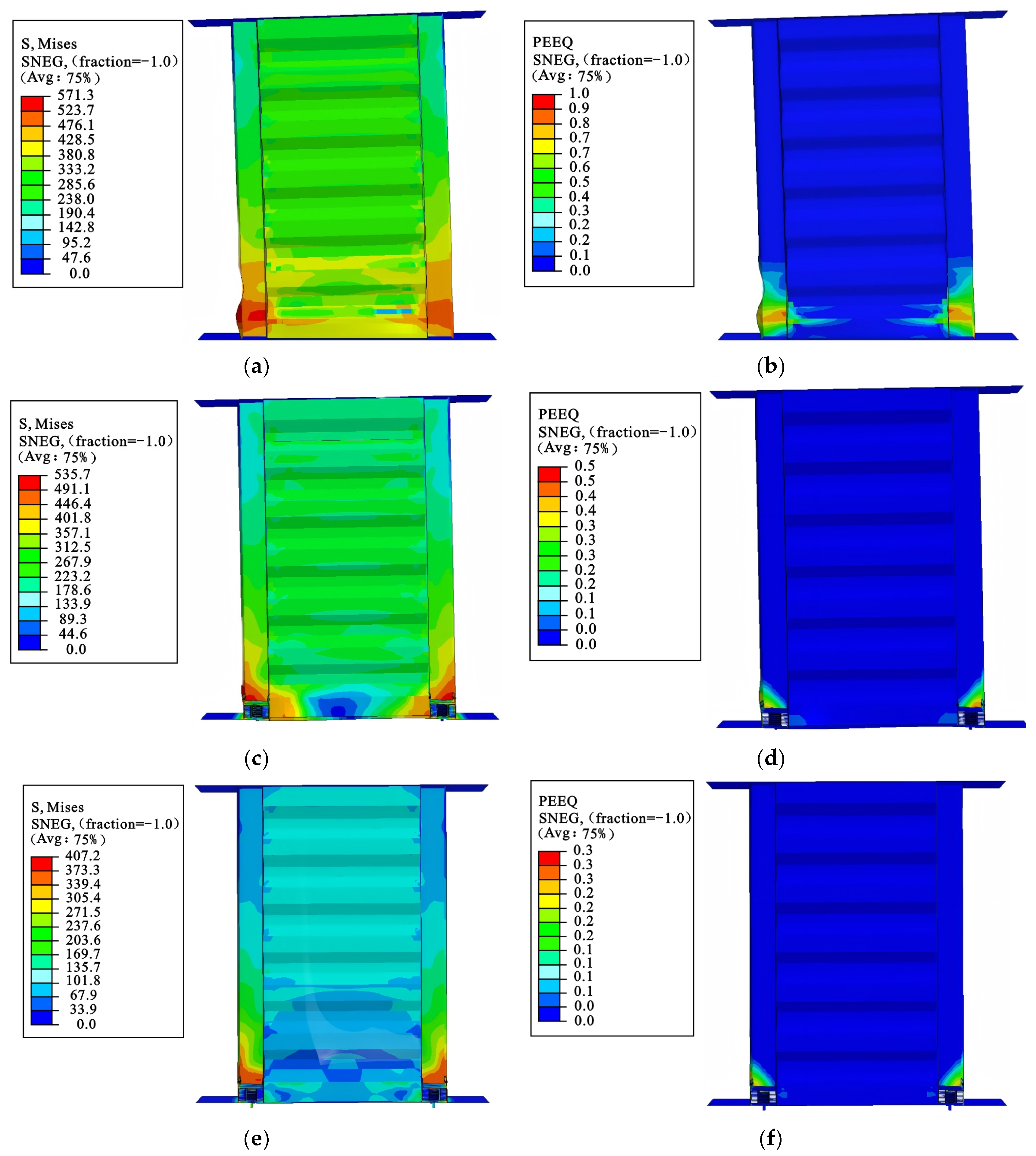
The Mises stress nephograms and plastic strain nephograms of the DCSPSW, M1, and M2 models at the ultimate displacement are selected for the analysis, as shown in Figure 21. It can be seen from the figures that the embedded corrugated steel plate of the DCSPSW model is subject to large stress and large out-of-plane buckling deformation, and the high stress areas are mainly concentrated on the toes at both sides, especially on the toes of the left wall. However, in the DCSPSW with the DSLRDD, the loosening of the vertical degree of freedom at the bottom makes the stress at the bottom of the embedded corrugated steel plate relatively small. Moreover, the high-stress area, large plastic deformation area, and major damage are all concentrated on the DSLRDD itself, thus protecting other parts of the wall and effectively improving the overall stability and seismic performance of the DCSPSW instead.

5.2.2. Deformation of the Wall Toe

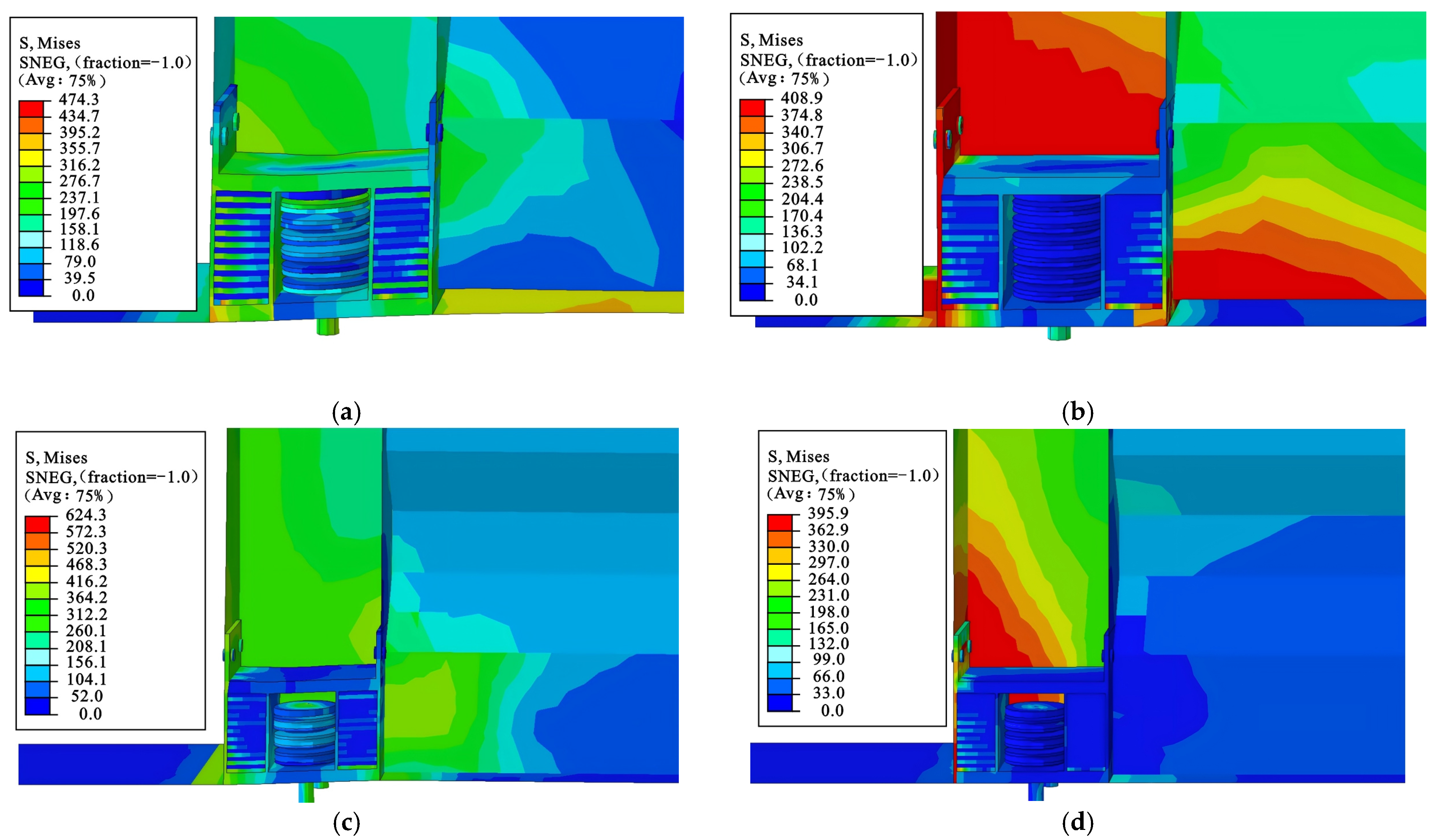
To analyze the mechanism of DSLRDD in DCSPSW, the toes of M1 and M2 models are locally magnified, and the stress nephograms of M1 and M2 models are shown in Figure 22. As can be seen from the figures, under the tensile state of the M1 and M2 models, the disc springs of the DSLRDD are in a compressed state, and there is a significant increase in stress, indicating that the disc springs are working in coordination. However, when the DSLRDD is under a compressive state, the laminated rubber works together to bear the force, and the disc springs do not generate stress due to the loosening of the vertical degree of freedom of the bottom plate. To summarize, it is recommended to install a DSLRDD with disc spring arrangement B at the toe of the DCSPSW.

5.2.3. Hysteresis Behavior

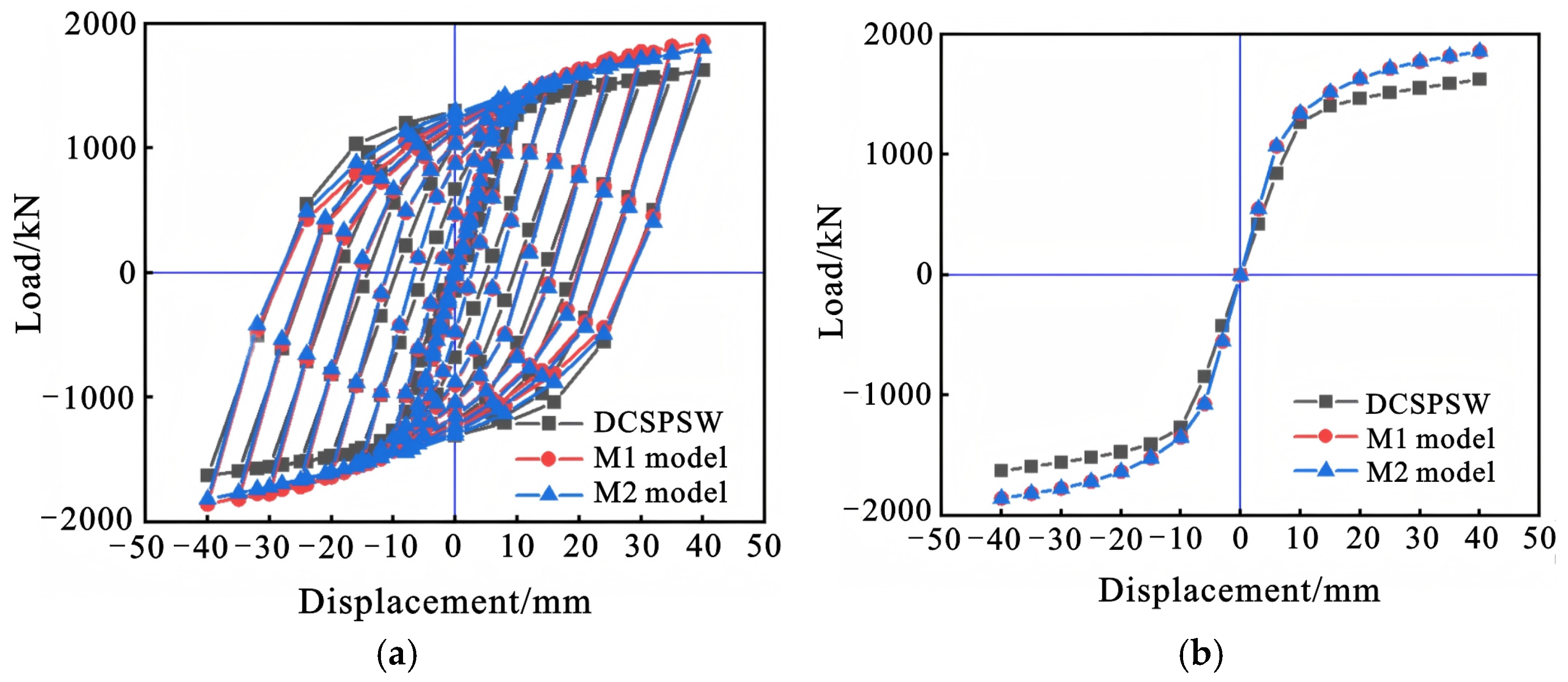
The hysteresis curves and skeleton curves of the DCSPSW, M1, and M2 models are shown in Figure 23. As can be seen from the figure, compared with the DCSPSW model, the hysteresis curves of the M1 and M2 models exhibit better plasticity and bearing capacity. The M1 and M2 models can absorb and dissipate seismic energy through the DSLRDD, delay the formation of structural plastic hinges, and make the overall deformation of the structure more uniform, thereby reducing the local concentrated damage of the structure and improving the energy dissipation capacity and ductility of DCSPSW. What is more, the M1 model performed slightly better than the M2 model, so in practical applications, it is recommended to install a DSLRDD with a disc spring superimposed B arrangement at the toe of the wall.

5.2.4. Key Mechanical Property Indicators

To further quantify the influence of the DSLRDD on the seismic performance of DCSPSW structure, peak loads, ductility coefficients, and energy dissipation factors of DCSPSW, M1 and M2 models are simulated, as shown in Table 5. Compared with the DCSPSW model, the peak loads of the M1 and M2 models are increased by about 14.4% and 14.1%, respectively, because of which the DSLRDD can absorb and dissipate part of the energy, reducing the stress peak transferred to the DCSPSW, thereby increasing the peak load of the DCSPSW. In terms of ductility coefficient, compared with the DCSPSW model, the ductility coefficients of M1 and M2 models increased by 30.8% and 28.1%, respectively, because of which the DSLRDD has a large deformation capacity, increasing the ductility of the DCSPSW. From the perspective of the energy dissipation factor, compared with the DCSPSW model, the energy dissipation factors of the M1 and M2 models are increased by 10.0% and 8.9%, respectively, which indicates that the DSLRDD can effectively reduce the stress and damage degree of the DCSPSW and increase the energy dissipation factor. In summary, compared with the DCSPSW model, the M1 and M2 models have a stronger bearing capacity and energy dissipation capacity and better seismic superiority. It is also recommended to choose the DSLRDD with disc spring stacking arrangement B at the toe of the DCSPSW wall.

6. Conclusions

In this paper, a new type of DSLRDD is proposed to solve the problem that DCSPSW wall toes are prone to failure under seismic action. Initially, the structure and basic principles of DSLRDD were introduced. Subsequently, three important design parameters of the DSLRDD were analyzed by numerical simulation to optimize its mechanical properties. Finally, the seismic performance of DCSPSW with DSLRDD was systematically studied. The main conclusions are given as follows:
(1)
The DSLRDD with disc spring stacking arrangement B and C has stronger deformation ability.
(2)
The stiffness control of DSLRDD is transferred between the rubber layer and the steel plate, so that the energy dissipation factor decreases first and then increases with the increase in the layer thickness ratio. Therefore, the stiffness and ductility requirements need to be comprehensively considered in selecting the thickness ratio of the steel plate to rubber layer, and the recommended value range is proposed as being 1.25~2.5.
(3)
With the increase in the yield strength of the steel plate, the strength of DSLRDD also increases, but the value change is not large. It is recommended that the yield strength of the steel plate is 400 MPa.
(4)
Compared with the DCSPSW, the stress of the DCSPSW with the DSLRDD is mainly concentrated on the DSLRDD itself instead of the DCSPSW toes, which shows better plasticity and bearing capacity. In the actual project, it is recommended to choose a DSLRDD with a simple structure, better energy dissipation capacity, and stacking arrangement B.
(5)
At present, this paper is limited to the simulation theory stage, and subsequent experiments will be carried out to consolidate the foundation of engineering application. In the future, it is planned to introduce components, such as magnetorheological elastomers, to improve the recovery force of the device and reduce the residual deformation of the structure after stress.

Author Contributions

Conceptualization, X.S. and B.W.; methodology, X.S.; software, Z.G. and B.W.; validation, B.W., and Z.Z.; formal analysis, B.W.; investigation, Z.G.; resources, B.W.; data curation, Y.S.; writing—original draft preparation, Z.G. and B.W.; writing—review and editing, Y.S. and Z.Z.; supervision, X.S.; project administration, X.S.; funding acquisition, X.S. All authors have read and agreed to the published version of the manuscript.

Funding

The financial support from the China Postdoctoral Science Foundation Funded Project (No. 2016M592732) and the Project funded by Key Research and Development Program of Shaanxi (No. 2021SF-525) is greatly appreciated.

Acknowledgments

The authors gratefully acknowledge all reviewers of the paper.

Conflicts of Interest

The authors declare no conflict of interest.

References

  1. Guo, Y.L.; Zhu, J.S. Research progress of shear walls: Types and design methods. Eng. Mech. 2020, 37, 19–33. [Google Scholar]
  2. Huang, L.; Hikosaka, H.; Komine, K. Simulation of accordion effect in corrugated steel web with concrete flanges. Comput. Struct. 2004, 82, 2061–2069. [Google Scholar] [CrossRef]
  3. Zhao, Q.H.; Li, Y.K.; Tian, Y. Cyclic behavior of double-skin composite walls with flat and corrugated faceplates. Eng. Struct. 2020, 220, 111013. [Google Scholar] [CrossRef]
  4. Chen, Z.P.; Zhou, J.; Mo, L.L.; Liao, H.Y.; Tang, J.Y. Experimental study on seismic behavior of double-skin corrugated plates and concrete composite shear wall. J. Build. Struct. 2022, 43, 199–213. [Google Scholar]
  5. Zhao, Q.H.; Li, N.; Sun, J.H. Analysis on lateral performance of sinusoidally corrugated steel plate shear walls. J. Tianjin Univ. (Sci. Technol.) 2016, 49, 152–160. [Google Scholar]
  6. Sun, J.H. Research on Lateral Performance and Seismic Behavior of Corrugated Steel Plate Shear Walls. Master’s Thesis, Tianjin University, Tianjin, China, 2017. [Google Scholar]
  7. Li, N. Experimental Research on Seismic Behavior of Corrugated Steel Plate Shear Wall System. Master’s Thesis, Tianjin University, Tianjin, China, 2018. [Google Scholar]
  8. Tong, J.Z.; Wu, R.M.; Xu, Z.Y.; Guo, Y.L. Subassemblage Tests on Seismic Behavior of Double-Corrugated-Plate Shear Walls. Eng. Struct. 2023, 276, 115341. [Google Scholar] [CrossRef]
  9. Du, Y.F.; Wang, Z.Z.; Li, H. Study on hysteretic performance of double-corrugated steel plate shear wall. J. Archit. Civil Eng. 2022, 39, 65–76. [Google Scholar]
  10. Wang, W.; Zhao, H.T.; Quan, C.C.; Song, H.L.; Zhou, Y.X. Research on Seismic Damage Repair of Vertical Corrugated Steel Plate Composite Shear Wall. World Earthq. Eng. 2022, 38, 67–79. [Google Scholar]
  11. Lu, X.L.; Chen, C. Research progress in structural systems with replaceable members. Earthq. Eng. Eng. Dyn. 2014, 34, 27–36. [Google Scholar]
  12. Ozaki, F.; Kawai, Y.; Tanaka, H.; Okada, T.; Kanno, R. Innovative Damage Control Systems Using Replaceable Energy Dissipating Steel Fuses for Cold-Formed Steel Structures. In Proceedings of the Twentieth International Specialty Conference on Cold-Formed Steel Structures, St. Louis, MO, USA, 3–4 November 2010. [Google Scholar]
  13. Ozaki, F.; Kawai, Y.; Kanno, R.; Hanya, K. Damage-control systems using replaceable energy-dissipating steel fuses for cold-formed steel structures: Seismic behavior by shake table tests. J. Struct. Eng. 2013, 139, 787–795. [Google Scholar] [CrossRef]
  14. Du, Y.F.; Wang, Z.Z. Study on seismic performance of rocking double-corrugated steel plate shear wall with replaceable dampers. Prog. Steel Build. Struct. 2022, 24, 1–18. [Google Scholar]
  15. Wang, W.; Zhao, Q.; Quan, C.C.; Li, Y.; Wang, X.F.; Xu, J. Study on mechanical performance and restoring force model of wall-toe replaceable metal dampers. J. Build. Struct. 2024, 45, 243–254. [Google Scholar]
  16. Lu, X.L.; Mao, Y.J. Design method for RC shear walls with replaceable foot parts. Struct. Eng. 2012, 28, 12–17. [Google Scholar]
  17. Mao, Y.J.; Lu, X.L. Quasi-static cyclic tests of RC shear wall with replaceable foot parts. J. Cent. South Univ. 2014, 45, 2029–2040. [Google Scholar]
  18. Liu, Q.Z.; Jiang, H.J. Experimental study on a new type of earthquake resilient shear wall. Earthq. Eng. Struct. Dyn. 2017, 46, 2479–2497. [Google Scholar] [CrossRef]
  19. Liu, Q.Z.; Jiang, H.J. Design method of new type of reinforced concrete shear wall with replaceable corner components and its analysis. J. Tongji Univ. 2016, 44, 37–44. [Google Scholar]
  20. Zhu, G.Z.; Liu, J.M.; Sun, J.T. Seismic performance of a new type of swaying self-resetting vertical tooth shear wall. J. Vibration Shock 2024, 43, 196–205. [Google Scholar]
  21. Chen, P.; Wang, B.; Zhang, Z.H.; Li, T.; Dai, K.S. A generalized model of lead rubber bearing considering large strain stiffening and degradation. Eng. Struct. 2023, 275, 115264. [Google Scholar] [CrossRef]
  22. Sato, E.; Furukawa, S.; Kakehi, A.; Nakashima, M. Full-scale shaking table test for examination of safety and functionality of base-isolated medical facilities. Earthq. Eng. Struct. Dyn. 2011, 40, 1435–1453. [Google Scholar] [CrossRef]
  23. Yang, D.L. Research on Vertical Displacement of Laminated Rubber Bearing Under Earthquake. Master’s Thesis, Kunming University of Science and Technology, Kunming, China, 2020. [Google Scholar]
  24. Gao, J.Y. Investigation on Three-Dimensional Disc Spring-High Damping Rubber Isolation Bearing. Master’s Thesis, Beijing University of Technology, Beijing, China, 2018. [Google Scholar]
  25. Zhuang, Z.; Zhang, F.; Cen, S. Nonlinear Finite Element Analysis and Examples with ABAQUS; Science Press: Beijing, China, 2005. [Google Scholar]
  26. Zhang, Z.D.; Zhou, Y. Study on compressive and tensile behaviors of thick rubber bearings. Eng. Mech. 2024, 41, 167–175. [Google Scholar]
  27. GB 50011-2010; Code for Seismic Design of Buildings. China Architecture & Building Press: Beijing, China, 2010.
  28. Xu, R.T. Study on Mechanical Properties of Self Compacting Concrete with CFRP-PVC Spiral Reinforcement. Master’s Thesis, Guangxi University, Guangxi, China, 2021. [Google Scholar]
  29. Li, L.J. Research on Behavior and Design Methods of Sinusoidal Steel Plate Wall. Master’s Thesis, Tsinghua University, Beijing, China, 2012. [Google Scholar]
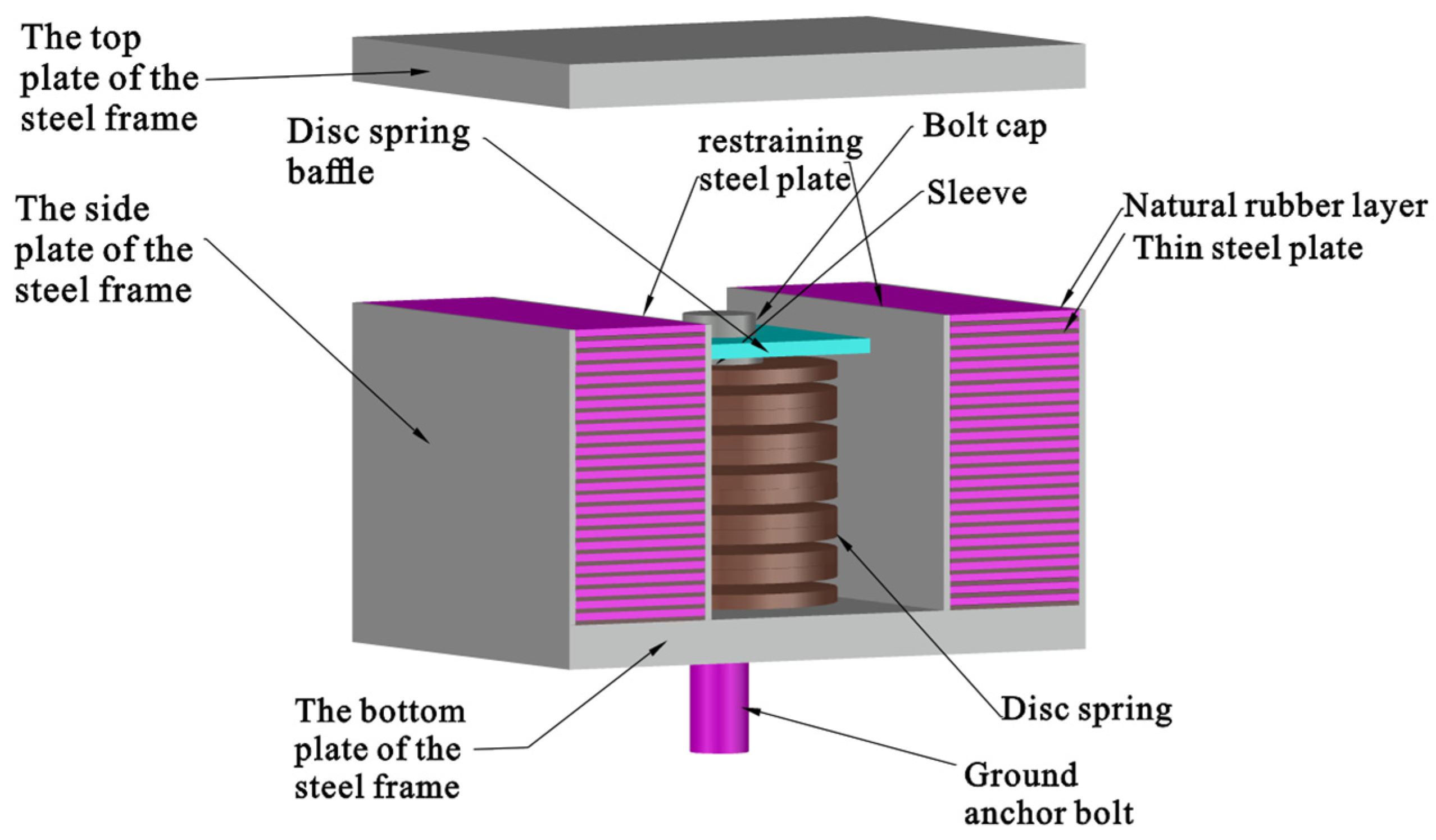
Figure 1. Configuration diagram of the DSLRDD.
Buildings 15 02903 g001
Figure 2. Schematic diagram of the constitutive relationship of steel.
Buildings 15 02903 g002
Figure 3. Finite element model of DSLRDD.
Buildings 15 02903 g003
Figure 4. Comparison of finite element and test results of laminated rubber: (a) Finite element model of the laminated rubber; (b) simulation results of unidirectional compressive mechanics.
Buildings 15 02903 g004
Figure 5. Comparison of finite element and test results of single disc spring: (a) Stress nephogram of single disc spring; (b) load–displacement curve of single disc spring.
Buildings 15 02903 g005
Figure 6. Energy consumption factor calculation model.
Buildings 15 02903 g006
Figure 8. Stress nephograms of specimens with different disc springs stacking arrangements:(a) F-A; (b) F-B; (c) F-C.
Buildings 15 02903 g008
Figure 9. Load–displacement curves of specimens with different disc springs stacking arrangements.
Buildings 15 02903 g009
Figure 10. Stress nephograms of specimens with different layer thickness ratios: (a) R-0.2; (b) R-0.4; (c) R-0.6; (d) R-0.8; (e) R-1.0; (f) R-1.25; (g) R-1.66; (h) R-2.5; (i) R-5.0.
Buildings 15 02903 g010
Figure 11. Load–displacement curves of specimens with different layer thickness ratios.
Buildings 15 02903 g011
Figure 12. Ductility coefficient variation curve of specimens with different layer thickness ratios.
Buildings 15 02903 g012
Figure 13. The variation curve of the energy dissipation factor of the specimens with different layer thickness ratios.
Buildings 15 02903 g013
Figure 14. Stress nephograms of specimens with different yield strengths of steel plates: (a) S-1; (b) S-2; (c) S-3; (d) S-4.
Buildings 15 02903 g014
Figure 15. Load–displacement curves of specimens with different steel plate yield strength.
Buildings 15 02903 g015
Figure 16. Ductility coefficient variation curve of specimens with different steel plate yield strengths.
Buildings 15 02903 g016
Figure 17. The variation curve of the energy dissipation factor of the specimen with different steel plate yield strengths.
Buildings 15 02903 g017
Figure 18. The dimensions of the corrugated steel plate.
Buildings 15 02903 g018
Figure 19. Comparison of the DCPSW-H2 specimen’s finite element and experimental hysteretic curves.
Buildings 15 02903 g019
Figure 20. Completed diagram of the model establishment: (a) DCSPSW model; (b) M1 model; (c) M2 model.
Buildings 15 02903 g020
Figure 21. Stress nephograms and plastic strain nephograms of three models: (a) Stress nephogram of DCSPSW; (b) plastic strain nephogram of DCSPSW; (c) stress nephogram of M1; (d) plastic strain nephogram of M1; (e) stress nephogram of M2; (f) plastic strain nephogram of M2.
Buildings 15 02903 g021
Figure 22. The stress nephograms of the DSLRDD in M1 and M2: (a) The tensile stress nephogram of the DSLRDD in M1; (b) the compressive stress nephogram of the DSLRDD in M1; (c) the tensile stress nephogram of the DSLRDD in M2; (d) the compressive stress nephogram of the DSLRDD in M2.
Buildings 15 02903 g022
Figure 23. Comparison of hysteretic curves and skeleton curves of three models: (a) Comparison of hysteresis curves; (b) comparison of skeleton curves.
Buildings 15 02903 g023
Table 1. Parameters of the Yeoh model of the rubber material.
C10C20C30D1D2D3
0.230.00130.0001760.005040.0050.000005
Table 3. Parameters of R-series specimens.
Specimen Numberts/mmtr/mmts/truhe
R-0.2150.202.1480.73
R-0.4250.402.1520.71
R-0.6350.602.1580.70
R-0.8450.802.1610.69
R-1.0551.002.1680.69
R-1.25541.252.1750.71
R-1.66531.662.1820.73
R-2.5522.502.1860.73
R-5.0515.002.1900.76
Table 4. Parameters of S-series specimens.
Specimen Numberts/mmtr/mmts/trfy/MPauhe
S-1350.602352.1510.74
S-2350.603352.1530.72
S-3350.604002.1580.70
S-4350.604202.1610.68
Table 5. Calculation results of mechanical properties of the three models.
Specimen NumberPp/KNuhe
DCSPSW1623.92.660.846
M11857.93.480.931
M21854.23.410.922
Disclaimer/Publisher’s Note: The statements, opinions and data contained in all publications are solely those of the individual author(s) and contributor(s) and not of MDPI and/or the editor(s). MDPI and/or the editor(s) disclaim responsibility for any injury to people or property resulting from any ideas, methods, instructions or products referred to in the content.