Article

A* Algorithm for On-Site Collaborative Path Planning in Building Construction Robots

1
School of Civil and Transportation Engineering, Guangdong University of Technology, No. 100 West Waihuan Road, Panyu District, Guangzhou 510006, China
2
Zhuhai Huafa Urban Operation and Investment Holdings Co., Ltd., Room 401, No. 9 Lian’an Road, Gongbei District, Zhuhai 519000, China
3
Department of Civil and Environmental Engineering, Kookmin University, 77 Jeongneung-ro, Seongbuk-gu, Seoul 02707, Republic of Korea
4
College of Water Conservancy and Civil Engineering, South China Agricultural University, No. 483 Wushan Road, Tianhe District, Guangzhou 510642, China
*
Author to whom correspondence should be addressed.
Buildings 2025, 15(21), 3876; https://doi.org/10.3390/buildings15213876
Submission received: 30 July 2025 / Revised: 12 October 2025 / Accepted: 22 October 2025 / Published: 27 October 2025
(This article belongs to the Special Issue Enhancing Building Resilience Under Climate Change)

Abstract

This study explores the use of construction robots with collaborative path planning and coordination in complex building construction tasks. Current construction processes involving robots are often fragmented due to their single-task focus, with limited research focused on employing multiple construction robots to collaboratively perform tasks. To address such a challenge, this research proposes an improved A* algorithm for global path planning and obstacle avoidance, combined with the development of a BIM-based grid map of the construction site. The leader–follower method is utilized to guide the robot group in maintaining an optimal formation, ensuring smooth collaboration during construction. The methodology includes formalizing building construction site environments into BIM-based grid maps, path planning, and obstacle avoidance, which allows robot groups to autonomously navigate and complete specific tasks such as concrete, masonry, and decoration construction. The results of this study show that the proposed approach achieves significant reductions in pathlength and operational time of approximately 9% and 10%, respectively, while maintaining safety and efficiency compared with traditional manual methods. This research demonstrates the potential of collaborative construction robot groups to enhance productivity, reduce labor costs, and provide a scalable solution for the intelligent transformation of the construction industry; extends the classical A* algorithm by incorporating obstacle density into the heuristic function; and proposes a new node simplification strategy, contributing to the literature on robot motion planning in semi-structured environments.

1. Introduction

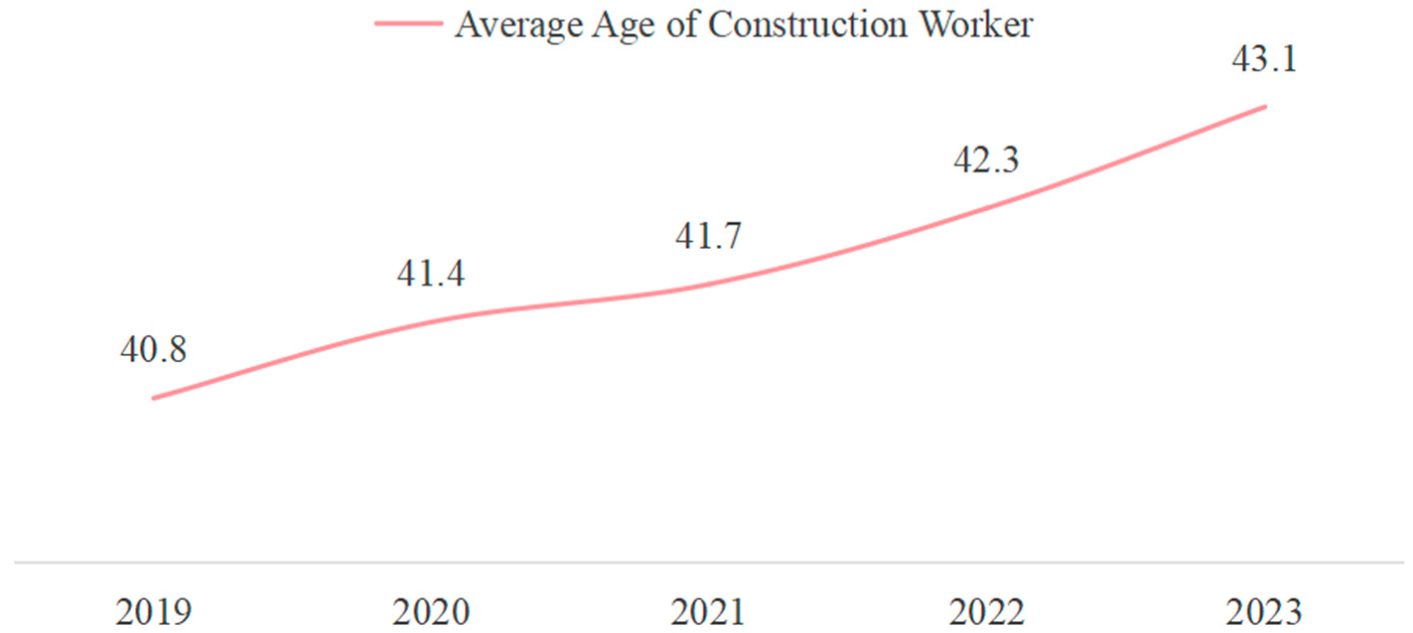
The construction industry, as a pillar of the national economy, serves as a critical platform for developing “new quality productivity.” However, the construction sectors worldwide have encountered developmental challenges, necessitating transformation and upgrades [1]. As shown in Figure 1 and Figure 2, both the labor force population and the number of construction workers in Mainland China have shown a fluctuating but overall declining trend from 2019 to 2023. Meanwhile, the average age of construction workers has exhibited a clear aging trajectory. In recent years, advancements in intelligent technologies have provided fresh momentum for global manufacturing, with the requirements for intelligence gradually permeating various fields. Smart construction, which integrates automation and informatization, has become a key driver for revolutionizing the construction industry [2,3]. Currently, construction industries across the globe still heavily rely on labor-intensive production and fragmented management methods. These practices result in low production efficiency, significant environmental burdens, and excessive resource consumption [4]. The introduction of the concept of smart construction presents a novel developmental opportunity and trend for the industry. To promote intelligent innovation within the construction sector, incorporating robotics technology into industry transformations and upgrades is imperative. By embedding robotics with intelligence and automation into construction processes, this initiative is poised to exert profound impacts on construction methods, business philosophies, industrial ecosystems, and enterprise development models [5].
The number of construction robots used for independent or assistive operations in building projects is gradually increasing in the construction industry. For instance, the MULE bricklaying robot developed in the United States enhances efficiency by assisting workers with bricklaying tasks through a lifting-and-gripping mechanism and a precision positioning system, achieving twice the efficiency of manual labor [6]. Similarly, Australia’s Hadrian X robot, equipped with an extendable robotic arm, can autonomously construct the walls of a single building, boasting a work efficiency three times higher than that of humans [7]. However, most building construction robots currently in use are limited to handling single tasks, which continues the fragmented nature of construction processes [8]. Consequently, these robots do not significantly improve efficiency or reduce costs of construction projects. To enhance the level of intelligence in the construction industry, some studies have proposed employing multiple construction robots to collaboratively perform tasks in laboratory settings. This approach aims to address the inefficiencies caused by sequential operations of individual robots but needs to be further utilized, considering its applicability to the real-world built work environment [9,10].
Collaborative operations among construction robots contribute to more organized construction workflows, reducing labor costs and scheduled time, thereby lowering overall project costs. Therefore, this study proposes a leader–follower collaborative operation method, which addresses the path planning challenge for a group of construction robots working collaboratively. The method involves mapping the real-world built work environment of construction robots, using an improved A* algorithm to plan the overall work path for the leader robot, and employing a leader–follower algorithm to coordinate the formation of follower robots. Although numerous studies have improved the A* algorithm and applied it to robotic path planning, few have explored the integration of path planning with coordinated multi-robot operations specifically in the context of construction tasks. This approach enables the construction robot group to perform building construction tasks in an orderly and efficient manner, offering a solution for the application of construction robots in real-world construction scenarios, with the contributions listed as follows:
The traditional A* algorithm was improved by incorporating obstacle density into the heuristic function and introducing a path-smoothing post-processing step to generate more efficient and realistic trajectories;
A collaborative path planning framework for construction robot groups was developed based on the leader–follower and BIM-based grid mapping approaches, enabling coordinated task execution in complex construction scenarios;
The effectiveness (i.e., planning time, planning length, path variation range, and success rate) was validated through real-world construction case studies, which also demonstrated its practical applicability.

2. Literature Review

The advancement of construction robotics heavily relies on effective path planning and robot group formation control. Path planning techniques, such as A*, Dijkstra’s algorithm, and Ant Colony Optimization, are essential for ensuring optimal routes in complex environments. Additionally, various group control strategies like the leader–follower, virtual structure, and behavior-based methods are employed to enable collaborative operations in construction tasks. These foundational approaches are integral to enhancing efficiency and safety in construction robot applications.

2.1. Path Planning Algorithms

The safe and efficient operation of construction robots on site relies on selecting a reasonable path to the construction location. Well-planned paths not only enhance construction efficiency and quality but also ensure safety and resource optimization. This is particularly crucial when coordinating multiple construction robots, where collaborative path optimization becomes even more important. Path planning methods can be categorized into global and local path planning, with global path planning being more commonly employed for mobile robots [11,12]. Prominent global path planning algorithms include the node-based A* algorithm, Dijkstra’s algorithm, and the Ant Colony Optimization algorithm.
The A* algorithm is a heuristic search method that evaluates the distance relationship between the current search position and the target location in real time, thereby improving search efficiency [13]. Numerous scholars have since made modifications to this algorithm to address various challenges. For instance, Li et al. [14] proposed a hybrid A* algorithm based on BINN, designing an improved bulldozer equipped with monitoring and autonomous path planning capabilities. This framework enables complete path planning, making the algorithm applicable in engineering practices. Similarly, Auh et al. [15] used the A* algorithm to plan the operational paths for cargo-handling robots in cluttered logistics environments, reducing collisions that could damage packaging while minimizing transport workload, time, and distance. Zhang et al. [16] improved the traditional A* algorithm by expanding the number of search nodes and increasing the search directions to 12, effectively addressing issues such as excessive path turns, uneven paths, and limited search ranges. These enhancements ensured optimal paths, improved safety by avoiding collisions, and increased precision, reducing path length. Zheng et al. [17] integrated an improved A* algorithm with the Timed Elastic Band (TEB) algorithm for motion control, enabling construction robots to navigate static and dynamic obstacles in indoor environments.
The Dijkstra algorithm is a classic solution for finding the shortest path in weighted graphs, often used for routing problems or as a subroutine in more complex graph algorithms [18]. Liu et al. [19] applied the Dijkstra algorithm for global indoor path planning of mobile robots and combined it with the Dynamic Window Approach for local path planning, enabling navigation and obstacle avoidance in building indoor environments. Alshammrei et al. [20] designed an optimized, collision-free algorithm based on the Dijkstra algorithm, achieving efficient path planning in obstacle-filled environments. This approach significantly reduced working time and costs for mobile robots.
The Ant Colony Optimization algorithm, proposed by Marco Dorigo, excels in global optimization but suffers from high computational requirements and a tendency to get trapped in local optima. Yen and Cheng [21] improved the traditional Ant Colony Optimization algorithm by integrating it with fuzzy control, enabling better adaptability in dynamic environments. Li et al. [22] optimized the pheromone update and transmission mechanisms in the Ant Colony Optimization algorithm, accelerating convergence and reducing the likelihood of local optima. Wu et al. [23] addressed the slow convergence and low efficiency of traditional Ant Colony Optimization algorithms by introducing a novel heuristic mechanism with directional information, improving the convergence speed, reducing path turns, and enhancing its practicality and efficiency in path planning.
Table 1 provides a comparative analysis of the three mainstream path planning algorithms—A*, Dijkstra, and Ant Colony algorithms—across several key performance indicators, including computational efficiency, scalability in ability to generate paths in complex site environments, and suitability in its practicality under the specific constraints of construction sites. While all three algorithms can successfully generate paths from the starting node to the destination, their characteristics differ significantly. The Ant Colony Optimization algorithm suffers from high computational overhead and a tendency to get stuck in local optima, making it unsuitable for complex construction scenarios. The Dijkstra algorithm ensures accurate shortest-path computation but lacks efficiency due to exhaustive node expansion. In contrast, the A* algorithm balances speed and optimality by leveraging heuristic functions and global information, enabling it to efficiently handle environments with static obstacles. Furthermore, the A* algorithm demonstrates scalability in multi-robot contexts and integrates easily with BIM-based grid maps, making it particularly well-suited for construction robot path planning. Therefore, this study builds upon the improved A* algorithm as the core of the proposed collaborative planning framework.

2.2. Robot Group Formation Control

Robot groups can achieve collaborative tasks, defense, and other desired outcomes through formation control, information sensing, data analysis, task allocation, trajectory planning, and formation stability control technologies. For construction robot groups performing collaborative tasks on construction sites, robot group formation methods can be referenced. Currently, widely applied methods for group formation include the leader–follower, virtual structure, and behavior-based formation methods.
The leader–follower method is one of the most commonly used methods for multi-robot collaborative formation control and is widely applied in robot and drone control fields [24]. The Robotics Automation Exploration and Perception Laboratory at the University of Pennsylvania has laid a solid theoretical foundation for the application of the leader–follower method in multi-robot systems, proposing two formation strategies: the L-ϕ method, which controls both the relative distance and the yaw angle of the robots, and the L-L control method, which only controls the relative distance [25]. In the application of the leader–follower method, Wu et al. [26] proposed using the leader–follower strategy for multi-robot obstacle avoidance formation control. By pre-setting the leader’s motion trajectory and adjusting the angle between the leader and followers during their movement, the robots can avoid obstacles, effectively solving the obstacle avoidance problem in multi-robot motion. Wang et al. [27] applied the leader–follower model for formation control of non-holonomic mobile robot groups in environments with unknown obstacles. They designed a bounded obstacle function to form constraints on the distance and orientation during the follower’s pursuit of the leader, enabling obstacle avoidance in unknown environments. Park and Yoo [28] proposed a leader–follower method that guarantees the connectivity between mobile robots, employing an obstacle avoidance strategy that maintains the connection between the leader and follower while avoiding obstacles, ensuring global connectivity even in the presence of obstacles. Li et al. [29] developed a novel virtual leader–leader–follower model based on the leader–follower method. In this model, the leader follows a reference trajectory determined virtual leader, and the followers track the desired position indicated by the virtual leader to solve the formation switching problem for mobile robots in environments with unknown obstacles.
The virtual structure method, proposed by Lewis et al. [30] from the University of California, is widely applied in formation flight control for aircraft and satellites [31]. In the virtual structure method, the entire formation is treated as a virtual rigid structure, where each agent is a fixed node in the relative position of the rigid body, and the agents follow the motion of the virtual structure. The group of agents moves with the rigid body in space, causing changes in their positions, but their relative positions remain unchanged, preserving the inherent geometric shape. The virtual structure method transforms the multi-agent formation problem into a tracking problem, offering high control accuracy and feedback on the formation, effectively controlling the overall behavior of the formation group [32]. Cai et al. [33] proposed a distributed model predictive control scheme based on virtual target guidance for controlling unmanned aerial vehicles (UAVs). In this method, each UAV shares information only with its neighbors, reducing the computational burden of UAV formation control and effectively achieving trajectory tracking and obstacle avoidance. Zhen et al. [34] proposed a method for multi-underwater vehicle formation control that combines artificial potential fields with the virtual structure. This combined control method ensures that the underwater vehicles avoid collisions during descent and can form and alter their formation once the desired depth is reached, achieving better mission detection outcomes.
The behavior-based formation method, proposed by Balch and Arkin [35], is a control approach inspired by biomimicry. It essentially involves a collection of behavioral actions such as obstacle avoidance, aggregation, formation change, and formation maintenance. Each action corresponds to a specific control method, with weights assigned to each action. The basic idea is to first design and coordinate the behaviors and then adjust and sum the weights of the behaviors to achieve the desired action set. In practical applications, Cheung et al. [36] proposed a behavior-based architecture to mitigate the impact of external disturbances on follower robots. They introduced a behavior manager that can create multiple behaviors to form a convoy controller combination, enabling the robot formation to maintain its movement even when subjected to disruptive attacks, thereby improving the robustness of the mobile robot team. Chen et al. [37] introduced a behavior-based decision-making path planning method, achieving behavior-based formation control and optimizing the diving paths of underwater robots to save energy and improve task efficiency. Table 2 compares the advantages and disadvantages of the above methods for collaborative formation control.
As shown in Table 2, the virtual structure method views the formation as a rigid structure, providing clear formation feedback and making it easy to maintain formation. However, since the formation must constantly maintain the same rigid structure, it lacks flexibility and adaptability, and there are certain limitations in the process of obstacle avoidance. This leads to the relatively limited application of the virtual structure method in multi-robot formation control. The advantage of the behavior-based formation method is that it allows for easier implementation of distributed control, and the system is more adaptable, effectively addressing collision avoidance issues. Additionally, the formation can achieve feedback through the perception between robots. However, the integration of behaviors in this method is complex, and the basic local behaviors for a robot to achieve a specified formation are difficult to design, which makes ensuring the stability of formation control hard. Therefore, this method is also rarely used in engineering applications. The leader–follower method, being the most commonly used formation control method, although highly dependent on the leader, has a simple control structure and is easy to implement. In this formation, the leader’s desired path is set, and the followers simply follow the leader with a predetermined positional offset to maintain the formation. Among the three mainstream formation control strategies, each presents distinct engineering trade-offs:
The leader–follower approach is easy to implement and highly effective in environments with clear navigation paths but is susceptible to leader failure and communication delays, making robustness a key concern.
The virtual structure method ensures rigid formation and accurate coordination but suffers from high computational overhead and limited scalability in complex or crowded construction sites.
Behavior-based control offers better fault tolerance and flexibility in dynamic environments but may lack formation stability and requires fine-tuned behavior rules.
Considering the semi-structured nature of most construction sites, the leader–follower model offers a practical compromise between control simplicity, system scalability, and formation robustness.

2.3. Summary of Current Research

As for path planning algorithms of construction robots, they can currently be divided into global and local path planning algorithms. For mobile robots applied in construction scenarios, global path planning algorithms such as A* algorithm, Dijkstra algorithm, and Ant Colony algorithm are generally used. Among these algorithms, the A* algorithm is particularly suitable for path planning in complex environments due to its faster and more efficient search process. It can also ensure the optimality of the path, even when there are static obstacles available.
In terms of collaborative formation methods for robots, the widely used methods include the leader–follower method, virtual structure method, and behavior-based formation method. However, since the latter two methods have limitations in engineering applications, such as flexibility and stability limitations, this study adopts the leader–follower method, which is easier to implement in construction scenarios.
Despite extensive applications of classical A* algorithm and its variants in robotics, few studies in the construction domain address the unique challenges of multi-robot coordination in cluttered and fragmented environments. To bridge this gap, we adopt a leader–follower formation strategy integrated with an improved A* algorithm that accounts for obstacle density and path smoothness. This approach directly responds to the need for scalable and efficient path planning in real-world construction scenarios by developing a collaborative path planning method for construction robots. The leader robot in the construction robot group uses an improved A* algorithm to plan a smooth path that avoids obstacles, while the follower robots in the group uses the leader–follower method to follow the path. This approach aims to validate the feasibility and applicability of construction robots working on building construction sites.

3. Methodology

This section outlines the methodology employed for analyzing and optimizing the collaborative work of construction robots. First, a detailed examination of collaborative building work scenarios for different types of robots is conducted, highlighting how these robots interact within specific construction environments. The process continues with the formalization of a work map, which is essential for enabling construction robots to navigate and perform tasks within a defined workspace. Finally, the proposed method integrates path planning and obstacle avoidance techniques, with an improved A* algorithm to enhance the robots’ ability to efficiently navigate complex environments. The methodology also incorporates a leader–follower approach for coordinating multiple robots in a collaborative setting, ensuring smooth operation and formation maintenance during construction tasks.

3.1. Analysis of Collaborative Work Scenarios for Construction Robots

To use specific construction robots for particular tasks, it is essential not only to select the appropriate type of robot but also to consider the work scenarios in which they will operate. Currently, various types of building construction robots are available on the market, including intelligent follow-up concrete placing robots for concrete construction, floor leveling robots, and floor finishing robots [38]; mortar spraying robots for secondary structure construction [39], block transport robots [40], and bricklaying robots [6]; as well as decoration robots such as putty coating robots, wallpaper laying robots, and wall tile laying robots [41]. While many construction robots have already been commercially deployed, the problem of collaborative work among construction robots requires specific robot combinations to form a group that can work together to complete building construction tasks. The work scenarios for these robots primarily include the following:
Collaborative Work Scenarios for Two Construction Robots: The collaboration between two construction robots is primarily applied to standard floor concrete construction and indoor wall and floor tile installation. For standard floor concrete construction, a floor leveling robot and a floor finishing robot typically work together in collaboration to complete the task. For indoor wall and floor tile installation, a wall tile laying robot and a floor tile laying robot collaborate with a block transport robot to perform the construction tasks.
Collaborative Work Scenarios for Three Construction Robots: Collaboration among three construction robots is typically applied to tasks that are more complex and involve multiple construction processes. Current scenarios where three construction robots work together include standard floor masonry construction and interior decorative coating spraying. Standard floor masonry construction involves collaboration between a block transport robot, a mortar spraying robot, and a bricklaying robot. The block transport robot handles material transportation, while the mortar spraying and bricklaying robots perform the masonry work. Interior decorative coating spraying involves collaboration between putty decoration and finishing robots, and an indoor spraying robot. The putty decoration and finishing robots first complete the basic puttying tasks, after which the indoor spraying robot applies the corresponding paint to finish the interior wall decoration.

3.2. Formalization of Robots’ Work Map

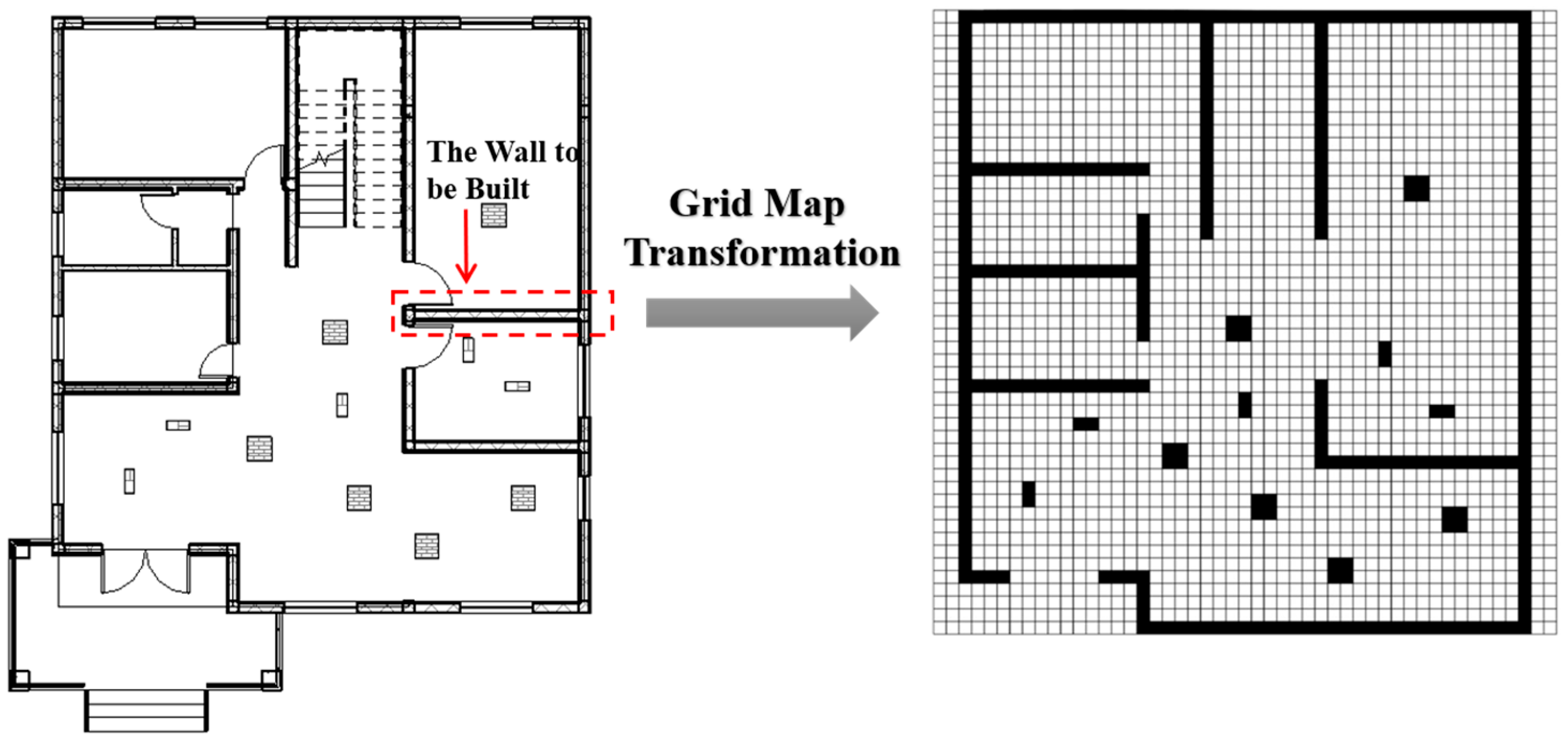
To enable construction robots to operate in a specific building working environment, the environment needs to be converted into a work map for the robots, allowing them to recognize and navigate it. In the field of robotics, there are three main types of map representations: metric, topological, and semantic maps [42]. For mobile construction robots, the most commonly used map type is metric maps, specifically the grid type. Due to its model simplicity and the uniqueness of its positional representation, grid maps are frequently used in path planning. A grid map divides the entire environment into several equally sized grids, and different representations are assigned to each grid based on the presence of obstacles. The advantage of using grid maps for path planning is that it allows the map to be drawn with sufficiently fine grids, enabling the representation of contours of arbitrary shapes [43]. Path planning based on grid maps can be performed in three directions—horizontal, vertical, and diagonal—allowing the robot to follow the planned path precisely. The steps to map the building construction site environment and build a grid map are shown in Figure 3:
Step 1: Collect building blueprint information to determine the geometry and location of each floor of the building.
Step 2: Use Building Information Modeling (BIM) technology to draw the building’s geometric and locational information diagram and create the construction robot’s working environment model.
Step 3: Set the grid plane parameters and mapping rules based on the construction robot’s working environment model.
Step 4: Complete the actual mapping of the work map based on the grid map and mapping rules, thus obtaining the construction robot’s working grid map.
In step 3, the mapping rules are primarily as follows: The white areas in the grid map are defined as free grids, indicating obstacle-free regions, while the areas with obstacles are represented by black grids, which indicate regions where the robot cannot pass. To facilitate understanding by computers, this environmental information is represented using a 0–1 matrix. A 0 represents free space, and a 1 represents an obstacle space.

3.3. Path Planning and Obstacle Avoidance for the Leader Robot Based on A* Algorithm

In building construction site operations, it is essential to ensure that the construction robots select a reasonable and effective path. Based on global path planning, the path must be optimized according to the site’s environment, allowing the construction robots to effectively avoid obstacles while selecting the shortest operational path.
Traditional A* Algorithm: for path planning in the construction industry, typically in static environments, the A* algorithm not only provides the shortest path but also ensures high search efficiency. The A* algorithm performs a directional search, utilizing the evaluation function in Formula (1) to calculate the distance from each node to the destination, thereby determining whether the node can be part of the shortest path.
f n = g n + h n
where f(n) is the estimated distance from the initial node to the target node through node N, g(n) represents the actual distance from the initial node to node N in the state space, and h(n) is the estimated distance from node N to the target node along the optimal path.
For the A* algorithm to guarantee optimality, the key lies in the selection of h(n). If h(n) represents the estimated distance from node N to the target node, then h∗(n) is the actual distance from node N to the target node. The strength of the heuristic function is measured by how closely h(n) approximates h∗(n). Ideally, h(n) ≤ h∗(n), and the more heuristic information h(n) contains, the closer it will be to h∗(n), resulting in a more optimal path.
Improved A* Algorithm for Path Planning and Obstacle Avoidance: While the traditional A* algorithm performs well in many cases, it also has certain limitations. In building construction sites, where numerous obstacles may exist, using the traditional A* algorithm for path planning may result in a locally optimal solution, making it unable to effectively address obstacle avoidance.
To adapt to the practical requirements of construction site operations, this study incorporates obstacle considerations into the path planning process. The algorithm is designed to favor paths with fewer obstacles during the search process. Dynamic weights are introduced into the evaluation function, factoring in the proportion of obstacles between the starting node and the target node. By incorporating an obstacle rate, the influence of the heuristic weight can be adjusted, encouraging the algorithm to prioritize paths with fewer obstacles. The modified evaluation function, i.e., f′(n), derived based on the above improvement approach, is as follows:
f n = g n + e q × p × h n
where ex is the exponential function in mathematics, and q represents the influence of the obstacle rate on the weight of the heuristic factor. This parameter adjusts the impact of obstacle density on the heuristic function. To guide the algorithm towards regions with fewer obstacles, a larger q value increases the impact of obstacles on path selection. If the path contains more obstacles, the heuristic function h(n) is multiplied by a larger weight, prompting the algorithm to choose paths with fewer obstacles.
The value of q is experimentally adjusted within a given environment. Typically, q is adjusted within a range of 1 to 10, and the optimal value for a specific environment is identified through iterative fine-tuning based on experimental results. To tune the dynamic weight parameter q in the heuristic function, we conducted empirical testing within a reasonable interval. If q is too small (e.g., approaching 0), the obstacle density term becomes insignificant, causing the algorithm to degenerate into the standard A* without improvements. Conversely, an excessively large q (e.g., greater than 10) leads to overly conservative planning, resulting in unnecessarily long detours or increased planning failures in dense environments. Therefore, we adopted a common tuning range of q ∈ [1,10], which balances global optimality and obstacle avoidance. Through simulation trials, we found that q = 5 produced the most effective results in terms of smoothness, path length, and planning success rate. This value was thus used in our implementation.
The parameter p represents the obstacle rate between the current and target node, calculated using Formula (3). In the local grid map between the current and target node, the number of obstacle grids is denoted as O. The current node’s coordinates are (xn, yn), and the target node’s coordinates are (xg, yg). When calculating the distance in each direction, one is added to ensure that the path length is not zero and to maintain stability in the calculations.
p = O x n x g + 1 y n y g + 1 , p 0,1
Path Improvement: The traditional A* algorithm often results in paths with excessive turning and redundant nodes. To address this issue, this study proposes a key node extraction method to filter out redundant nodes from the A* algorithm’s planned path. This approach shortens the path length, reduces turning nodes, and makes the overall working path smoother, thereby improving the operational efficiency of construction robots. The optimization steps are as follows:
Obtain the complete set of nodes U = {Pi∣1 ≤ In} from the A* algorithm’s planned path, where P1 represents the starting node and Pn represents the end node of the path. Create an initial key node set V = {P1, Pn}, which initially includes only the starting and ending nodes of the path and is used to store the optimized key nodes.
Starting from P1, draw a straight line connecting the nodes sequentially in U, i.e., P2, P3, …, Pi, and check if the straight line P1Pi intersects any obstacles:
If the line P1Pi does intersect an obstacle, the node Pi−1 is deemed a critical node and a necessary turning node in the path and is added to the set V.
If the line P1Pi does not intersect any obstacles, nodes P2, …, Pi−1 are considered redundant. Continue extending the line from Pi to subsequent nodes in U until it reaches the end node Pn, adding all identified key nodes to V.
After selecting the key nodes, the set V contains all critical nodes. Sequentially connect all nodes in V to globally optimize the path, i.e., remove redundant nodes and smooth the planned path.

3.4. Path Planning for Collaborative Construction Robot Groups

The leader robot uses the A* algorithm for path planning and obstacle avoidance. On this basis, the leader–follower approach is introduced to control the collaborative formation of the construction robot group. The follower robots follow the leader robot and actively avoid obstacles. This approach enables the robot group to follow the leader robot along a defined path while maintaining a specific formation, ensuring orderliness during the construction process. The leader robot employs the Improved A* Algorithm for global path planning, generating a reference path for the construction robot group. Based on the real-time positioning of the leader robot and the desired formation, the relative distance and angle of each follower robot to the leader are used to calculate the position of the virtual leader robot. The position of the virtual leader is then transmitted to the corresponding follower robot as a target node, guiding each follower robot to move toward its respective target.
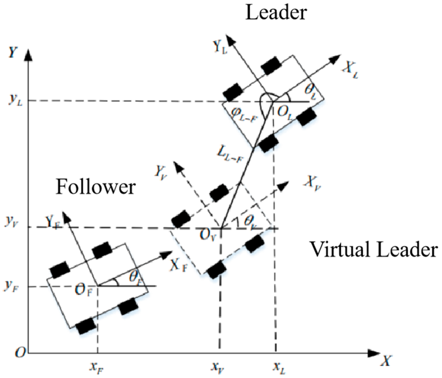
The model of the leader robot in the global coordinate system is shown in Figure 4, where
The global coordinate system is represented by XOY.
The local coordinate system of the leader robot is represented by XLOLYL.
The position of the leader robot in the global coordinate system is defined as (xL, yL, θL), where
xL, yL are the coordinates of the leader robot in the global coordinate system;
θL is the angle between the orientation of the leader robot and the X-axis in the global coordinate system.
The velocity vector of the leader robot in the global coordinate system is expressed as [44].
x ˙ y ˙ θ ˙ = c o s θ L s i n θ L 0 s i n θ L c o s θ L 0 0 0 1 v x v y ω
where
x ˙ ,   y ˙ ,   a n d   θ ˙ represent the leader robot’s linear velocities in the x and y directions and angular velocity in the global coordinate system;
vx, vy, and ω represent the leader robot’s linear velocities in the x and y directions and angular velocity in the local coordinate system.
As shown in Figure 5, assume the position of the follower robot is (xF, yF, θF). Based on the formation requirements, let the position of the virtual leader be (xV, yV, θV). The expected distance between the virtual leader and the leader robot is LL−F, and the expected angle is φ L F . Using the expected distance and angle, the position of the virtual leader in the global coordinate system can be expressed as
x V = x L + L L F cos φ L F + θ L y V = y L + L L F sin φ L F + θ L θ V = θ L
The proposed objective is to ensure that the position of the follower converges to that of the virtual leader robot. In other words, the follower’s final destination should align with the virtual leader robot’s position, rather than the position of the leader robot. Therefore, the position error function is constructed as follows:
x d = x V x F y d = y V y F θ d = θ V θ F
where xd, yd, and θd represent the position error between the virtual leader and the follower robot in the global coordinate system. Using a transformation matrix, the position error in the global coordinate system can be converted into the local coordinate system of the follower robot as follows:
d x d y d θ = c o s θ F s i n θ F 0 s i n θ F c o s θ F 0 0 0 1 x d y d θ d
where dx, dy, and dθ represent the position error between the virtual leader and the follower robot in the local coordinate system of the follower robot. Substituting Formula (5) into Formula (6) and simplifying, the error function in the follower robot’s local coordinate system can be expressed as
d x d y d θ = c o s θ F ( x V x F ) + s i n θ F ( y V y F ) s i n θ F ( x V x F ) + c o s θ F ( y V y F ) θ V θ F
Substituting the position formula of the virtual leader robot in the global coordinate system into the error function in the local coordinate system, i.e., Formula (5) into Formula (8), and differentiating Formula (8) yields
d x ˙ = v L c o s d θ + ω F d y v F ω L L L F sin ( φ L F + d θ ) d y ˙ = v L ω F d x + ω L L L F cos φ L F + d θ d θ ˙ = ω V ω F
As can be seen from Formula (9), the robot formation control problem is transformed into a trajectory tracking problem for the follower robot relative to the virtual leader robot. When the error is minimized, the follower robot converges to the position of the virtual leader. At this point, the follower robot moves to the virtual leader’s position using the optimal linear and angular velocities computed, thus completing the formation of the robot group.

4. Case Studies

This study uses masonry work on the standard floor of a building construction project as the tested collaborative work scenario for construction robots, a widely adopted and mature application scenario in the domain. The masonry construction scenario was selected as the case study due to its representative characteristics. First, the task involves repetitive block transport, mortar spraying, and bricklaying, which facilitates the measurement and control of robotic behaviors. Second, masonry sites typically include a cluttered and semi-structured environment, with common construction obstacles such as stacked bricks, scaffolding, and temporary barriers. Lastly, masonry tasks inherently require multi-robot collaboration, as the supply of materials must be coordinated with the bricklaying operation. These features make masonry an ideal and challenging scenario to evaluate the effectiveness of coordinated robot path planning in real-world conditions.
The selected robots include a block transport robot, a mortar spraying robot, and a bricklaying robot to perform path planning for the masonry task collaboratively. The masonry work that the construction robots need to complete is highlighted within the red frame in the BIM model shown in Figure 6, where the work environment contains various obstacles of different sizes.
Figure 6 shows the grid transformation of the BIM model, where the environmental information is represented by black-and-white grid cells. The blank grids are referred to as free grids, indicating areas without obstacles where the robot can pass through, while the black grids represent obstacle grids, indicating areas with obstacles that the construction robot cannot pass through. Figure 7 converts the environmental information into a computer-readable language represented by a 0–1 matrix. In this matrix, 1 represents an obstacle-occupied space, which the robot cannot pass, while 0 represents a free space, where the robot can move freely.

4.1. A* Algorithm-Based Path Planning and Obstacle Avoidance Model for the Leader Robot

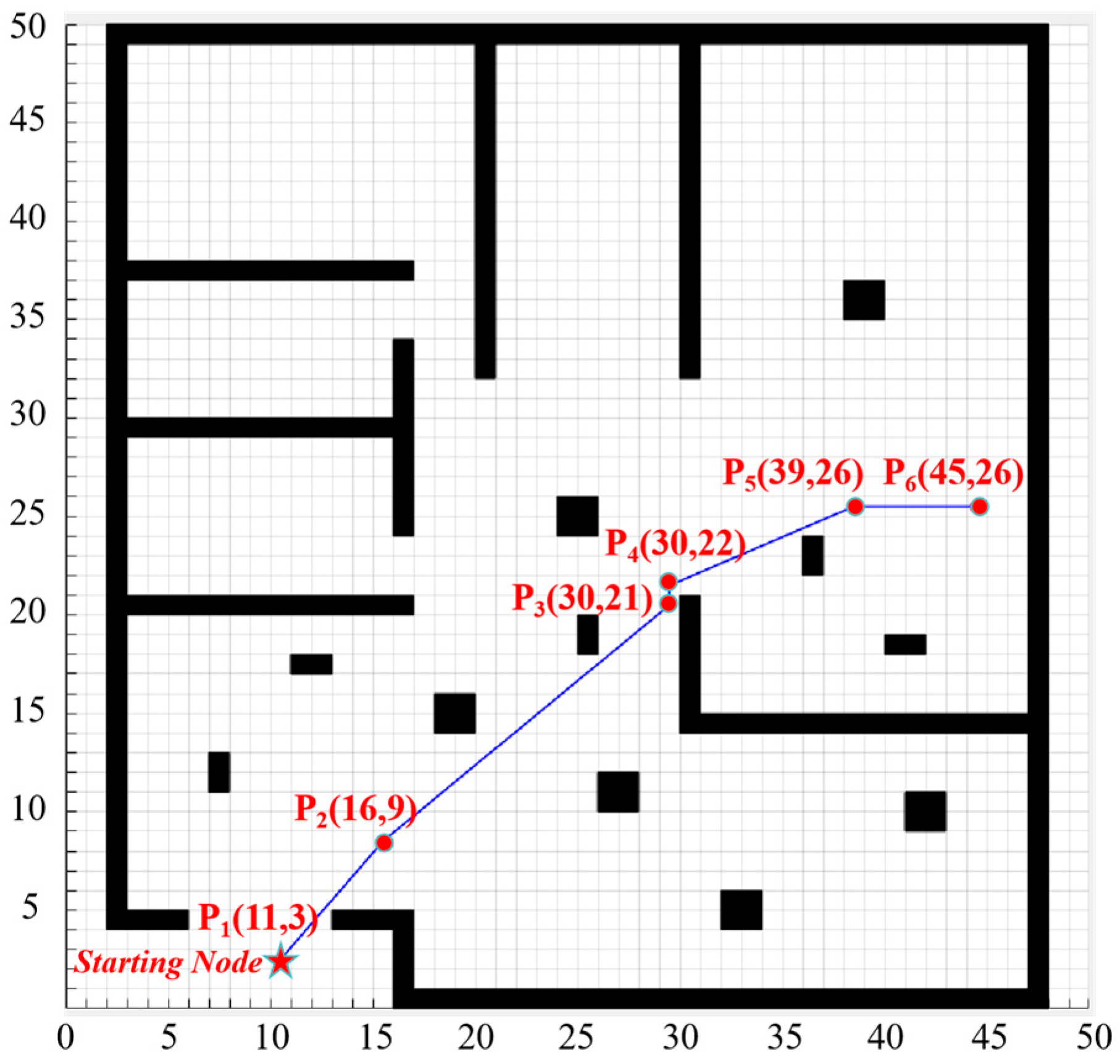
An improved A* algorithm is employed for path planning to enable the leader robot to find an optimal work path. The planning process is presented in Figure 8. The starting node A is set at coordinates (11, 3), and the end node B is set at coordinates (45, 26), corresponding to the location of the wall construction task in as discussed in Section 4.2. The improved A* algorithm is implemented for path planning simulation using MATLAB (Version R2022b).
This study improves the A* algorithm. The leader robot uses the improved A* algorithm for global path planning based on the path planning process, resulting in an optimal global path that avoids obstacles to the greatest extent. The evaluation function of the improved A* algorithm used in the path planning experiment is as follows:
f n = g n + e 5 × p × h n
The obstacle rate p is determined jointly by the obstacle environment in Figure 9 and Formula (3). To match the real construction environment, the influence value q of the obstacle rate on the heuristic factor weight is adjusted within the range of 1 to 10 in the environment provided in Figure 9. Given the presence of a certain number of obstacles in the environment and to better balance the path length and safety in the improved A* algorithm, a middle value of q (i.e., q = 5) is chosen, which results in an ideal effect.
After the algorithm finds the path, to simplify and smoothen the path, key nodes are identified and redundant nodes are removed, thus obtaining the optimal path. The set V is used to store the key nodes in the path, and the coordinates of the key nodes of the optimized path are presented in Table 3.
The nodes in key node set V are indicated in red in Figure 9. After constructing the key node set, the key nodes are sequentially connected from the starting node. The resulting smooth curve is the planned optimal path, which is a work path for the leader robot that avoids obstacles and is smoother. As shown in Figure 9, the construction robot starts from the doorway and, during while approaching the work area, effectively avoids the obstacle-dense areas in the working environment. The planned path using the improved A* algorithm avoids obstacles and maintains a smooth path, making the work process safer and more efficient.

4.2. Collaborative Path Planning for a Group of Construction Robots

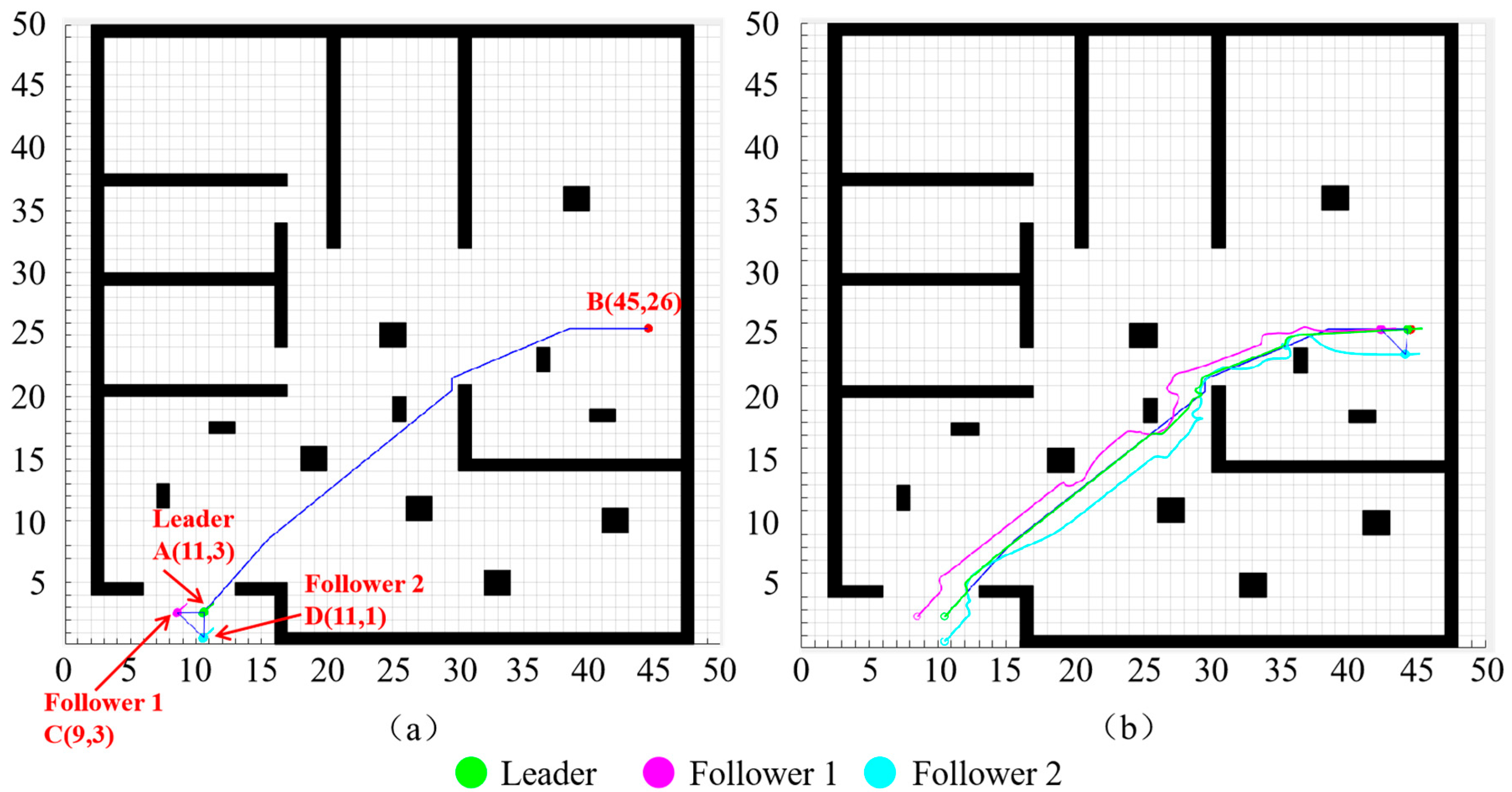
In this case, the mortar spraying robot acts as the leader robot, while the bricklaying and block transport robots function as Followers 1 and 2, respectively. After the leader robot uses the improved A* algorithm for path planning, the followers, under the leader–follower control strategy, follow the leader while maintaining a specific formation to perform collaborative tasks. The starting node of the leader robot is A with coordinates (11, 3), and the end node B is at coordinates (45, 26). The initial heading angle of the leader robot is set as θL = π/4, so the leader robot’s position is (11, 3, π/4). The distance from the leader robot to the followers is set as L(L-F) = 2, with the initial angles φ(L-F) set to π/2 and 3π/4, respectively. Therefore, the initial positions of follower robots C and D are (9, 3, π/4) and (11, 1, π/4), respectively. The relevant parameters for the simulation are set as listed in Table 4. The simulation process is shown in Figure 10.
During operation, to maintain the formation, the follower robots are guided by a virtual leader. The virtual leader maintains a constant distance L L F = 2 from the leader robot while guiding its movement. The follower robots utilize the error optimization function, as shown in Formula (5), to minimize the error, allowing the follower robots to converge at the position of the virtual leader. At this point, the follower robots calculate the optimal linear and angular velocities to move to the position of the virtual leader, as shown in Figure 11, thus completing the collaborative formation path planning task for the robot group.

4.3. Discussion

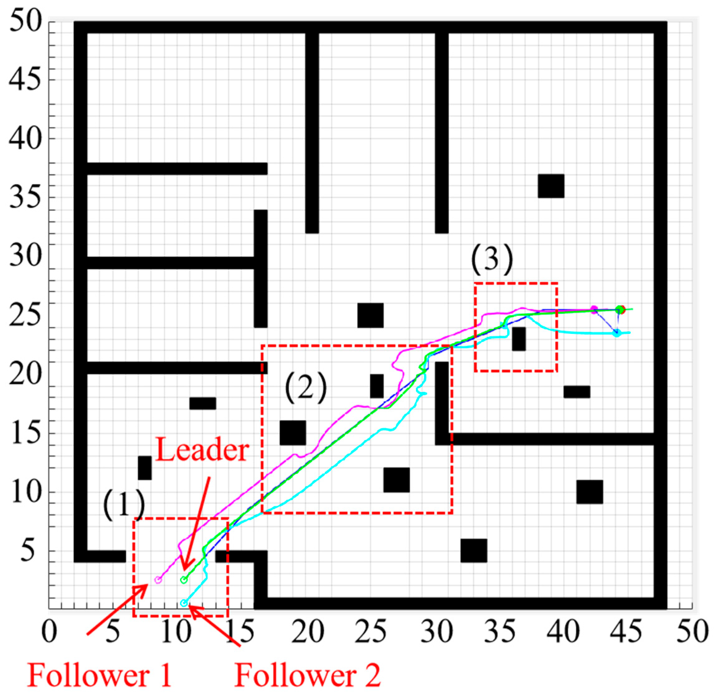
The changes in the heading angles of the leader and follower robots are shown in Figure 10. The three construction robots start from the initial position with a heading angle θ = π/4. During movement, Follower 2 first reaches the obstacle area (1). To avoid the wall on the right side of the obstacle area (1), Follower 2 adjusts its angle to achieve obstacle avoidance. Simultaneously, to maintain the formation of the robot group, Follower 1 also adjusts its angle accordingly. From the start node to the end node, due to the presence of multiple obstacles in the environment, the follower robots (Followers 1 and 2) continuously adjust their heading angles by a certain magnitude to ensure that the leader robot operates along the optimal path while maintaining formation. After passing the obstacle area (1), the heading angle changes for both the leader and follower robots, gradually stabilizes, and becomes smoother.
As the leader robot moves along the planned optimal path, which avoids obstacle-dense areas and is relatively smooth, the overall change in its heading angle is small, with a significant heading angle adjustment only occurring near the obstacle area (2). In contrast, the two follower robots, while maintaining a fixed formation and avoiding obstacles, experience more frequent heading angle adjustments throughout the movement. However, as the number of obstacles decreases or after passing the obstacle area (3) and nearing the end node, the variations in heading angle of the follower robots gradually decrease, eventually stabilizing and converging to a fixed value as they reach the end node and complete the motion. This indicates that even when encountering obstacles, the robot group can maintain a consistent working angle throughout the collaborative operation, ultimately reaching the target position efficiently and effectively.
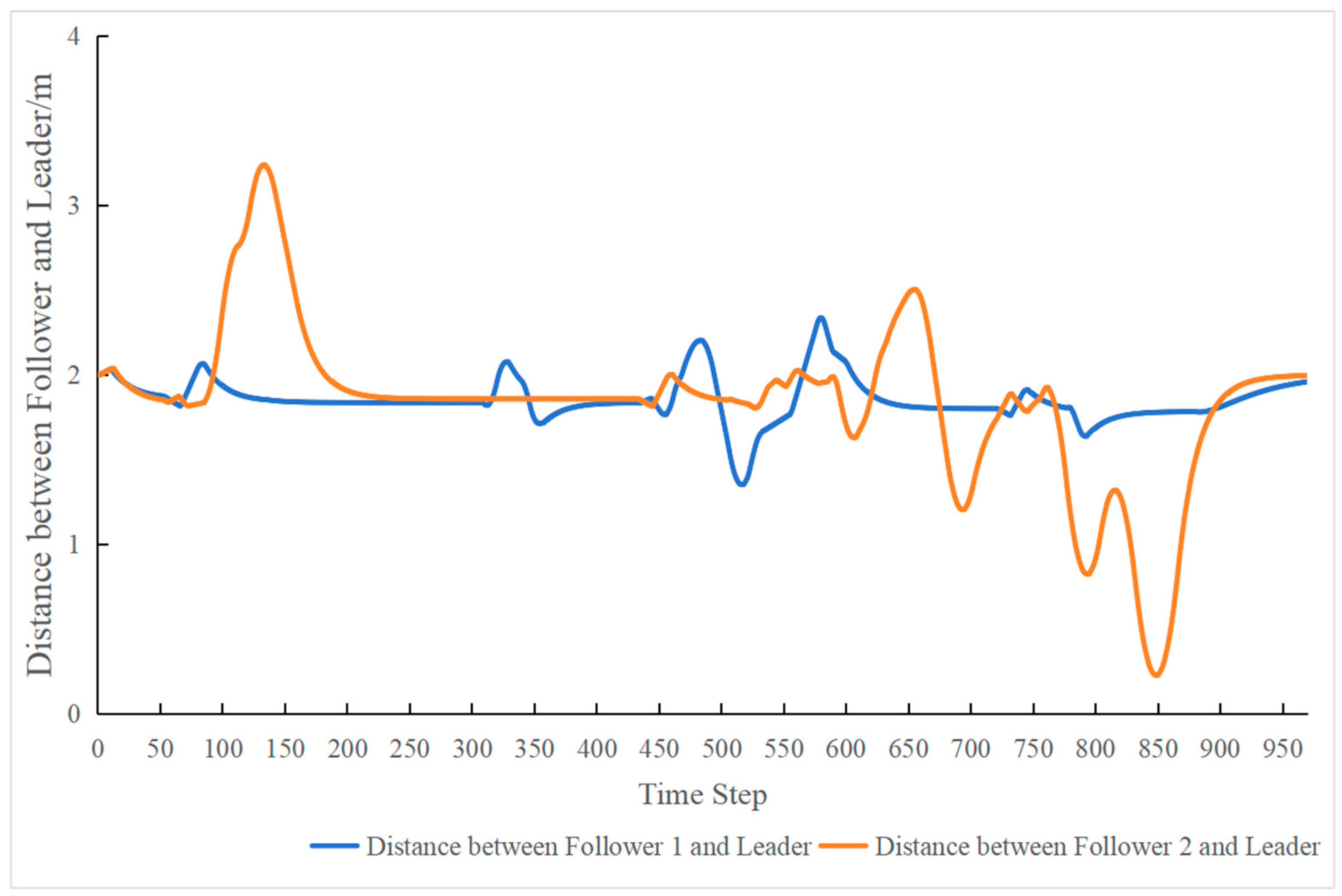
The variation in the distance between the robot group and the leader robot during movement is shown in Figure 12 and Figure 13. At the start of the motion, the leader and follower robots maintain the desired distance L(LF) = 2. During the movement, when the follower robots encounter obstacles, their distances from the leader robot fluctuate to varying degrees. In obstacle-dense areas, the fluctuation in distance between the follower robots and the leader robot is more pronounced. Once the robots move away from the obstacles, the fluctuation in distance gradually stabilizes, eventually returning to the initially set desired distance L(LF) = 2 at the end node. This demonstrates that during collaborative operation, even when obstacles are encountered, the distance between the leader and the follower robots may experience variation. Nevertheless, the robot group can maintain a consistent distance throughout the operation, ultimately reaching the target position effectively.
In summary, applying this leader–follower algorithm, after setting the initial heading angle and desired distance between the leader robot and the follower robots, the follower robots may temporarily deviate in angle and distance during operation due to obstacle avoidance. However, after passing through obstacles, the follower robots and the leader robot can return to the initially set heading angle and distance to continue moving. Similarly, when the position of the leader robot changes, both follower robots can make appropriate position adjustments to maintain the formation. Ultimately, the robots converge to the designated positions with a specific angle and distance.
While this study focuses primarily on planning efficiency, path smoothness, and successful task completion rate, it does not incorporate additional performance indicators such as energy consumption, communication overhead, or robustness under dynamic obstacles. These dimensions will be explored in future studies to enhance the practical applicability of the proposed system.
This framework provides a feasible pathway for enabling collaborative operations in construction environments, addressing the limitations of traditional single-robot deployment. From a theoretical perspective, the proposed method contributes to the body of knowledge on multi-agent systems by operationalizing leader–follower dynamics in semi-structured, obstacle-rich environments such as construction sites. This study also supports the integration of decentralized coordination and modular formation control into the robotics-in-construction paradigm.
In terms of practical implications, the reduced path variation, shorter planning time, and higher task success rates imply enhanced productivity and operational safety. While quantitative cost data were not collected in this study, the use of automated coordination among robots holds promise for reducing labor dependence and minimizing rework, especially in repetitive masonry tasks. This aligns with current industry trends toward automation under labor shortages.
Despite these contributions, certain limitations must be acknowledged. The method relies on accurate obstacle mapping and assumes static obstacle conditions. In highly dynamic environments, real-time perception and replanning capabilities would be necessary to ensure robustness. Additionally, the leader–follower model, while effective for coordination, may face challenges in scalability and flexibility when applied to larger, more heterogeneous robot teams. Future work will focus on addressing these challenges by incorporating adaptive formation strategies and dynamic reconfiguration mechanisms.

4.4. Verification

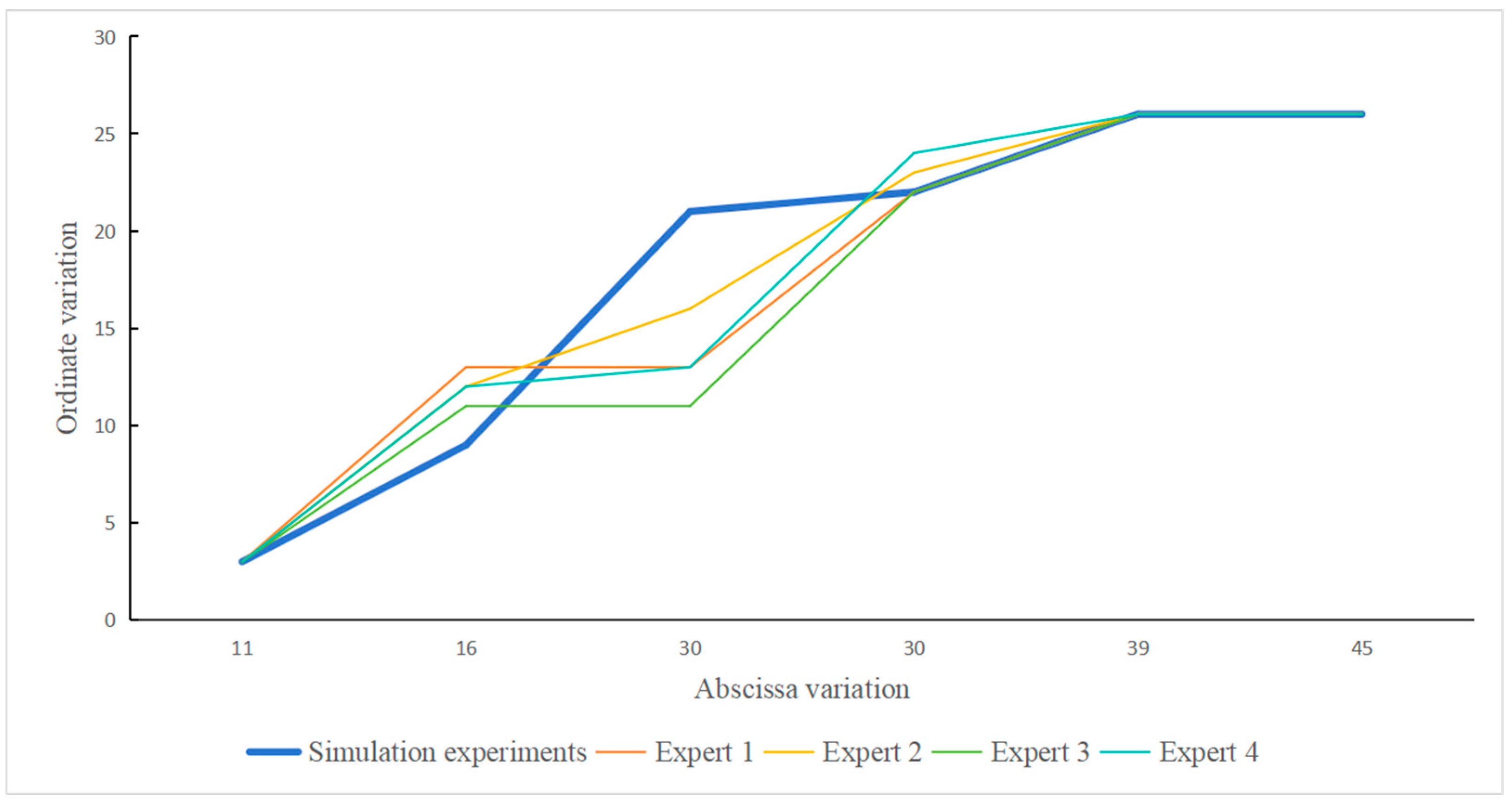
To verify that the proposed on-site collaborative path planning for construction robots conformed to those in practical engineering applications, this study invited four experts (with an average of eight years of experience) to evaluate the proposed method. A grid map containing obstacles, obtained through environmental mapping, was provided to them. Under the condition of predefined start and end node locations, the participants were asked to manually plan a path on the provided grid map. The results of the manual path planning were compared with those generated based on the improved A* algorithm proposed in this study. A fitting analysis was conducted to compare the coordinate variations in the manually optimized path and the one generated by the proposed method (Figure 14).
R 2 = 1 R S S T S S
R S S = 1 6 ( y i y s ) 2
T S S = 1 6 ( y i y ¯ ) 2
To analyze the degree of fit between the manual results and the one generated by the proposed method, this study uses the coefficient of determination R2 for evaluation. This metric is widely used to measure the degree of difference between predicted and actual values [45].
Here, yi represents the i-th vertical coordinate of the key nodes in the path planned by the technicians, and y ¯ is the mean of the vertical coordinates of the key nodes in the manually planned path. ys represents the i-th vertical coordinate of the key nodes in the path generated from the proposed method. The R2 value, calculated using Formula (10), is used to evaluate the fit between the manually planned paths and those generated using the proposed method. The Total Sum of Squares (TSS) represents the sum of the squared differences between the dependent variable and its mean. The Residual Sum of Squares (RSS) represents the sum of the squared differences between the values generated using the proposed method and the dependent variable. The closer the R2 value is to 1, the better the fit. Conversely, an R2 value closer to 0 or negative indicates a poor fit.
To simplify calculations and balance precision with efficiency, this study substitutes the coordinates of the selected key nodes from the proposed method (Figure 11) and the corresponding node coordinates obtained manually (Figure 14) into Formulas (11) and (12) for the calculation of R2. The fitting results are shown in Table 5. The goodness-of-fit values between the paths planned by the four experts based on their experience and the ones from the proposed method are approximately between 0.7 and 0.9. This indicates that the collaborative path planning for construction robots meets the requirements of actual construction site operations, demonstrating a certain degree of conformity.
Table 6 compares the average performance metrics between the path generated using the proposed method and manually, including task completion time, path length, path variation, and task success rate. The results show that collaborative path planning for construction robots demonstrates more significant advantages. The optimal path planned in the proposed method reduced planning time by nearly 10% compared to the manually planned paths. The path generated by the proposed method not only exhibited smaller variations and smoother transitions but also reduced path length by approximately 9%. This demonstrates that the proposed method in this study can also effectively achieve optimal values. Furthermore, a risk of collisions or near collisions exists in the manually planned paths, resulting in a task success rate of approximately 75%, where the path generated by the proposed method achieved a better result.
The path generated in the proposed method reduced planning time by nearly 10% compared to the path planned by experts. Additionally, the path generated in the proposed method exhibited smaller variations, greater smoothness, and an approximately 9% shorter path length. These results indicate that the proposed method in this study can achieve a better optimal level. Furthermore, due to the potential for collisions or near-collisions in manual path planning for construction robots, the success rate of completing the assigned task was smaller at approximately 75%. Although the validation involved four experts with an average of eight years of construction experience, this qualitative approach was adopted to ensure that the algorithmic path planning aligns with real-world operational logic. Their evaluations helped confirm that the simulation results are not only computationally optimal but also practically feasible. Future studies will incorporate quantitative validation using multiple benchmarks and real-world robotic deployment scenarios to enhance methodological robustness.

5. Conclusions

Addressing challenges such as limited automation, high dependency on manual labor, and prolonged construction timelines in traditional processes, researchers have increasingly focused on integrating construction robots to perform specific tasks. This approach not only seeks to improve construction efficiency but also aims to enhance automation within the industry, thereby offering innovative solutions for industry transformation. Beyond individual robots, the introduction of robot groups into construction tasks offers a more effective solution for handling complex, labor-intensive operations. This strategy significantly reduces labor dependence, increases efficiency, standardizes processes, and lowers overall construction costs. Additionally, the collaborative nature of robot groups ensures better coordination, leading to safer, more streamlined construction operations.
This study primarily investigates the path planning challenges associated with the collaborative operation of construction robot groups. By introducing an improved A* algorithm for the path planning and obstacle avoidance of leader robots and employing a leader–follower approach to guide the follower robots, this study offers a framework for collaborative navigation. The developed solution enables construction robot groups to autonomously identify and follow the safe and optimal paths within a construction environment. This research makes contributions to the field of smart construction and enhances the understanding of collaborative path planning and formation control for multi-robot systems operating in building construction settings.
Theoretical Contribution: This work extends the classical A* algorithm by incorporating obstacle density into the heuristic function and proposes a new node simplification strategy, contributing to the literature on robot motion planning in semi-structured environments.
Methodological Contribution: The integration of BIM-based grid mapping with multi-robot formation control demonstrates a systematic framework applicable to indoor masonry scenarios, providing a replicable simulation-to-field workflow.
Practical Contribution: Comparative results reveal that the proposed method shortens path length and reduces execution time by approximately 9–10% compared to expert-defined paths and increases the task completion success rate from 75% to 100%, highlighting practical advantages for labor-intensive and repetitive on-site tasks.
While this study demonstrates the feasibility and validity of collaborative path planning in simulated construction scenarios, several real-world constraints have not yet been incorporated into the current framework. These include sensor measurement errors, real-time communication latency between robots, and dynamic hazards such as unexpected obstacle appearances or human interference. To address these challenges, future research should aim to integrate robust perception technologies, such as millimeter-wave radar and computer vision systems, to enhance environmental awareness and obstacle detection in dynamic jobsite conditions. Additionally, incorporating these uncertainties into both simulation and field experiments will enable the development of more resilient and deployable planning frameworks for construction robotics. The application of artificial intelligence in decision-making could further optimize robot collaboration, improving both operational efficiency and autonomous capabilities on active construction sites.
The improved A* algorithm in this study focuses on minimizing global path length as a key indicator of efficiency; we acknowledge that this metric alone does not fully represent real-world task performance. In practical construction settings, the total task completion time is influenced by additional factors such as the robot’s acceleration and deceleration profiles, turning angles, and the logical sequence of construction tasks. Future studies should therefore consider a multi-objective optimization framework that incorporates these temporal and kinematic constraints to better reflect real-world operational demands.
This study is involved in the ongoing development of more intelligent, automated construction processes, with potential implications for improving productivity, safety, and sustainability within the construction industry.

Author Contributions

This study was conducted through a collaborative effort among all authors, each contributing to different aspects of the research. The roles and responsibilities of each author are outlined as follows: Y.F.: Writing—Original Draft, Methodology, Investigation, and Conceptualization; J.H.: Writing—Review and Editing, Data Curation, Software, and Visualization; X.W.: Software; W.X.: Methodology, Data Curation, and Validation; J.I.K.: Software and Validation; X.C. (Corresponding Author): Writing—Review and Editing, Funding Acquisition, and Project Administration. All authors have read and agreed to the published version of the manuscript.

Funding

The research described in this paper was conducted with the support of the Guangdong Natural Science Foundation (Grant #2022A1515110888), Guangzhou Natural Science Foundation (Grant #2023A04J1560), Guangdong Postgraduate Education Foundation (Education Development Grants #2024ANLK_024), Guangdong Science and Technology Innovation Program for Water Resources (Grant #2025-02), and South China Agricultural University Foundation (Education Development Grants #K23157/2022). The authors appreciate the support.

Data Availability Statement

The original contributions presented in this study are included in the article. Further inquiries can be directed to the corresponding author.

Conflicts of Interest

Author Wensheng Xu was employed by the company Zhuhai Huafa Urban Operation and Investment Holdings Co., Ltd. The remaining authors declare that the research was conducted in the absence of any commercial or financial relationships that could be construed as a potential conflict of interest.

References

  1. Zhu, Z.; Ning, S. Corporate digital transformation and strategic investments of construction industry in China. Heliyon 2023, 9, e17879. [Google Scholar] [CrossRef]
  2. Guo, Q.; Zhong, J. The effect of urban innovation performance of smart city construction policies: Evaluate by using a multiple period difference-in-differences model. Technol. Forecast. Soc. Change 2022, 184, 122003. [Google Scholar] [CrossRef]
  3. Lindsay, N.; Buehling, R.K.; Sun, L. A Sequential Task Addition Distributed Assignment Algorithm for Multi-Robot Systems. J. Intell. Robot. Syst. 2021, 102, 51. [Google Scholar] [CrossRef]
  4. Zhao, X.; Cheah, C.C. BIM-based indoor mobile robot initialization for construction automation using object detection. Autom. Constr. 2023, 146, 104647. [Google Scholar] [CrossRef]
  5. Gharbia, M.; Chang-Richards, A.; Lu, Y.; Zhong, R.Y.; Li, H. Robotic technologies for on-site building construction: A systematic review. J. Build. Eng. 2020, 32, 101584. [Google Scholar] [CrossRef]
  6. Melenbrink, N.; Werfel, J.; Menges, A. On-site autonomous construction robots: Towards unsupervised building. Autom. Constr. 2020, 119, 103312. [Google Scholar] [CrossRef]
  7. Pan, W.; Li, R.; Bock, T. Design and synthesis of the localization system for the onsite construction robot. In ISARC. Proceedings of the International Symposium on Automation and Robotics in Construction, Online, 27–29 October 2020; IAARC Publications: Edinburgh, UK, 2020; Volume 37, pp. 1501–1507. [Google Scholar]
  8. Wang, X.; Wang, S.; Menassa, C.C.; Kamat, V.R.; McGee, W. Automatic high-level motion sequencing methods for enabling multi-tasking construction robots. Autom. Constr. 2023, 155, 105071. [Google Scholar] [CrossRef]
  9. Wang, D.; Deng, H. Multirobot coordination with deep reinforcement learning in complex environments. Expert Syst. Appl. 2021, 180, 115128. [Google Scholar] [CrossRef]
  10. Ye, X.; Guo, H.; Luo, Z. Two-stage task allocation for multiple construction robots using an improved genetic algorithm. Autom. Constr. 2024, 165, 105583. [Google Scholar] [CrossRef]
  11. Fang, W.; Liao, Z.; Bai, Y. Improved ACO algorithm fused with improved Q-Learning algorithm for Bessel curve global path planning of search and rescue robots. Robot. Auton. Syst. 2024, 182, 104822. [Google Scholar] [CrossRef]
  12. Zhang, J.; Zhu, Z.; Xue, Y.; Deng, Z.; Qin, H. Local path planning of under-actuated AUV based on VADWA considering dynamic model. Ocean Eng. 2024, 310, 118705. [Google Scholar] [CrossRef]
  13. Hart, P.E.; Nilsson, N.J.; Raphael, B. A Formal Basis for the Heuristic Determination of Minimum Cost Paths. Ieee Trans. Syst. Sci. Cybern. 1968, 4, 100–107. [Google Scholar] [CrossRef]
  14. Li, R.; Zhou, C.; Dou, Q.; Hu, B. Complete coverage path planning and performance factor analysis for autonomous bulldozer. J. Field Robot. 2022, 39, 1012–1032. [Google Scholar] [CrossRef]
  15. Auh, E.; Kim, J.; Joo, Y.; Park, J.; Lee, G.; Oh, I.; Pico, N.; Moon, H. Unloading sequence planning for autonomous robotic container-unloading system using A-star search algorithm. Eng. Sci. Technol. Int. J. 2024, 50, 101610. [Google Scholar] [CrossRef]
  16. Zhang, Z.; Wang, S.; Zhou, J. A-star algorithm for expanding the number of search directions in path planning. In Proceedings of the 2021 2nd International Seminar on Artificial Intelligence, Networking and Information Technology (AINIT), Shanghai, China, 15–17 October 2021. [Google Scholar]
  17. Zheng, H.; Dai, M.; Zhang, Z.; Xia, Z.; Zhang, G.; Jia, F. The Navigation Based on Hybrid A Star and TEB Algorithm Implemented in Obstacles Avoidance. In Proceedings of the 2023 29th International Conference on Mechatronics and Machine Vision in Practice (M2VIP), Queenstown, New Zealand, 21–24 November 2023. [Google Scholar]
  18. Dijkstra, E.W. A note on two problems in connexion with graphs. Numer. Math. 1959, 1, 269–271. [Google Scholar] [CrossRef]
  19. Liu, L.; Lin, J.; Yao, J.; He, D.; Zheng, J.; Huang, J.; Shi, P. Path Planning for Smart Car Based on Dijkstra Algorithm and Dynamic Window Approach. Wirel. Commun. Mob. Comput. 2021, 2021, 8881684. [Google Scholar] [CrossRef]
  20. Alshammrei, S.; Boubaker, S.; Kolsi, L. Improved Dijkstra Algorithm for Mobile Robot Path Planning and Obstacle Avoidance. Comput. Mater. Contin. 2022, 72, 5939–5954. [Google Scholar] [CrossRef]
  21. Yen, C.; Cheng, M. A study of fuzzy control with ant colony algorithm used in mobile robot for shortest path planning and obstacle avoidance. Microsyst. Technol. 2018, 24, 125–135. [Google Scholar] [CrossRef]
  22. Li, J.; Wang, H. Research on AUV Path Planning Based on Improved Ant Colony Algorithm. In Proceedings of the 2020 IEEE International Conference on Mechatronics and Automation (ICMA), Beijing, China, 13–16 October 2020. [Google Scholar]
  23. Wu, L.; Huang, X.; Cui, J.; Liu, C.; Xiao, W. Modified adaptive ant colony optimization algorithm and its application for solving path planning of mobile robot. Expert Syst. Appl. 2023, 215, 119410. [Google Scholar] [CrossRef]
  24. Wang, P.K.C. Navigation strategies for multiple autonomous mobile robots moving in formation. J. Robot. Syst. 1991, 8, 177–195. [Google Scholar] [CrossRef]
  25. Desai, J.P.; Ostrowski, J.; Kumar, V. Controlling formations of multiple mobile robots. In Proceedings of the 1998 IEEE International Conference on Robotics and Automation (Cat. No.98CH36146), Leuven, Belgium, 20 May 1998. [Google Scholar]
  26. Wu, X.; Wang, S.; Xing, M. Observer-Based Leader-Following Formation Control for Multi-Robot with Obstacle Avoidance. IEEE Access 2019, 7, 14791–14798. [Google Scholar] [CrossRef]
  27. Wang, Y.; Wang, D.; Yang, S.; Shan, M. A Practical Leader–Follower Tracking Control Scheme for Multiple Nonholonomic Mobile Robots in Unknown Obstacle Environments. IEEE Trans. Control Syst. Technol. 2019, 27, 1685–1693. [Google Scholar] [CrossRef]
  28. Park, B.S.; Yoo, S.J. Connectivity-maintaining obstacle avoidance approach for leader-follower formation tracking of uncertain multiple nonholonomic mobile robots. Expert Syst. Appl. 2021, 171, 114589. [Google Scholar] [CrossRef]
  29. Li, X.; Liu, X.; Wang, G.; Wu, S.; Li, W. Adaptive virtual leader–leader–follower based formation switching for multiple autonomous tracked mobile robots in unknown obstacle environments. J. Frankl. Inst. 2024, 361, 106762. [Google Scholar] [CrossRef]
  30. Lewis, M.A.; Kar-Han, T. High Precision Formation Control of Mobile Robots Using Virtual Structures. Auton. Robot. 1997, 4, 387–403. [Google Scholar] [CrossRef]
  31. Beard, R.W.; Lawton, J.; Hadaegh, F.Y. A coordination architecture for spacecraft formation control. IEEE Trans. Control Syst. Technol. 2001, 9, 777–790. [Google Scholar] [CrossRef]
  32. Ding, W.; Zhang, L.; Zhang, G.; Wang, C.; Chai, Y.; Yang, T.; Mao, Z. Research on obstacle avoidance of multi-AUV cluster formation based on virtual structure and artificial potential field method. Comput. Electr. Eng. 2024, 117, 109250. [Google Scholar] [CrossRef]
  33. Cai, Z.; Wang, L.; Zhao, J.; Wu, K.; Wang, Y. Virtual target guidance-based distributed model predictive control for formation control of multiple UAVs. Chin. J. Aeronaut. 2020, 33, 1037–1056. [Google Scholar] [CrossRef]
  34. Zhen, Q.; Wan, L.; Li, Y.; Jiang, D. Formation control of a multi-AUVs system based on virtual structure and artificial potential field on SE(3). Ocean Eng. 2022, 253, 111148. [Google Scholar] [CrossRef]
  35. Balch, T.; Arkin, R.C. Behavior-based formation control for multirobot teams. IEEE Trans. Robot. Autom. 1998, 14, 926–939. [Google Scholar] [CrossRef]
  36. Cheung, C.; Rawashdeh, S.; Mohammadi, A. Jam Mitigation for Autonomous Convoys via Behavior-Based Robotics. Appl. Sci. 2022, 12, 9863. [Google Scholar] [CrossRef]
  37. Chen, G.; Shen, Y.; Qu, N.; He, B. Path planning of AUV during diving process based on behavioral decision-making. Ocean Eng. 2021, 234, 109073. [Google Scholar] [CrossRef]
  38. Ding, L.; Jiang, W.; Zhou, Y.; Zhou, C.; Liu, S. BIM-based task-level planning for robotic brick assembly through image-based 3D modeling. Adv. Eng. Inform. 2020, 43, 100993. [Google Scholar] [CrossRef]
  39. Cho, J.; Lee, J.; Kim, Y.; Shin, K. An analysis model for wind resistance performance of automated exterior wall painting robots in apartment buildings. KSCE J. Civ. Eng. 2014, 18, 909–919. [Google Scholar] [CrossRef]
  40. Jung, J.; Lee, S.; Myung, H. Indoor Mobile Robot Localization and Mapping Based on Ambient Magnetic Fields and Aiding Radio Sources. IEEE Trans. Instrum. Meas. 2015, 64, 1922–1934. [Google Scholar] [CrossRef]
  41. Yu, S.; Ryu, B.; Lim, S.; Kim, C.; Kang, M.; Han, C. Feasibility verification of brick-laying robot using manipulation trajectory and the laying pattern optimization. Autom. Constr. 2009, 18, 644–655. [Google Scholar] [CrossRef]
  42. Ben Salah, I.; Kramm, S.; Demonceaux, C.; Vasseur, P. Summarizing large scale 3D mesh for urban navigation. Robot. Auton. Syst. 2022, 152, 104037. [Google Scholar] [CrossRef]
  43. Thrun, S. Learning metric-topological maps for indoor mobile robot navigation. Artif. Intell. 1998, 99, 21–71. [Google Scholar] [CrossRef]
  44. Dierks, T.; Jagannathan, S. Control of Nonholonomic Mobile Robot Formations: Backstepping Kinematics into Dynamics. In Proceedings of the 2007 IEEE International Conference on Control Applications, Singapore, 1–3 October 2007. [Google Scholar]
  45. Zhang, H.; Wu, Z. The general goodness-of-fit tests for correlated data. Comput. Stat. Data Anal. 2022, 167, 107379. [Google Scholar] [CrossRef]
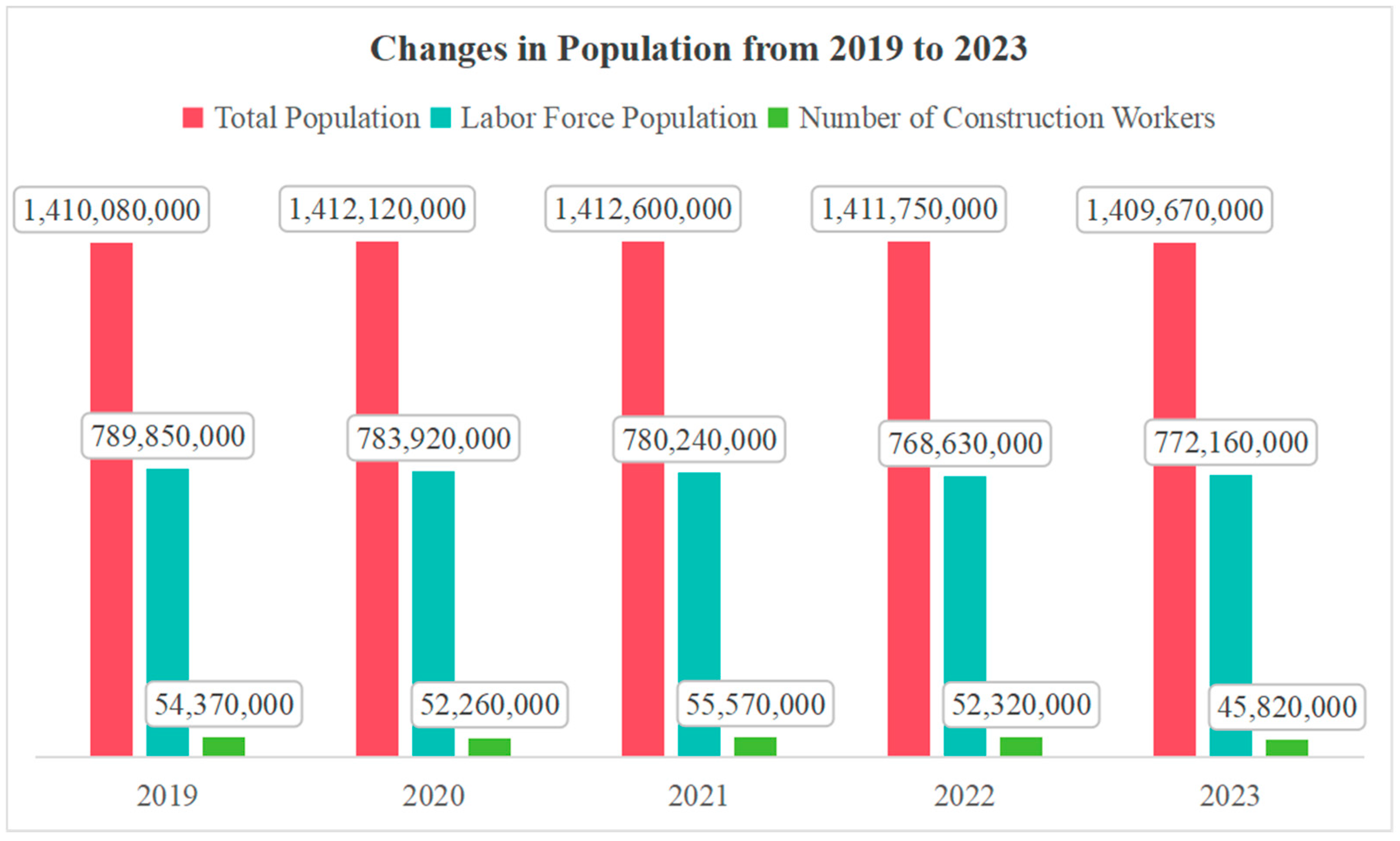
Figure 1. Changes in population from 2019 to 2023.
Buildings 15 03876 g001
Figure 2. Changes in average age of construction workers from 2019 to 2023.
Buildings 15 03876 g002
Figure 3. Formalization of building’s grid map.
Buildings 15 03876 g003
Figure 4. Mathematical model of the leader robot.
Buildings 15 03876 g004
Figure 5. Mathematical model of the follower robot.
Buildings 15 03876 g005
Figure 6. BIM model and grid conversion environment for the construction robot.
Buildings 15 03876 g006
Figure 7. Grid map conversion to 0–1 matrix.
Buildings 15 03876 g007
Figure 8. The proposed path planning process.
Buildings 15 03876 g008
Figure 9. The key nodes and improved path.
Buildings 15 03876 g009
Figure 10. Path planning for collaborative operation of robot group based on leader–follower approach. (a) The starting nodes of the leader, Follower 1 and 2 robots (b) The paths generated for the leader, Follower 1 and 2 robots.
Buildings 15 03876 g010
Figure 11. The main obstacle areas of the robot group working path.
Buildings 15 03876 g011
Figure 12. Changes in the heading angles of the leader and follower robots. (a) Changes in the heading angle between Follower 1 and Leader. (b) Changes in the heading angle between Follower 2 and Leader.
Buildings 15 03876 g012
Figure 13. The variation in distance L between the leader and follower robots.
Buildings 15 03876 g013
Figure 14. Coordinate variations for the paths generated using the proposed method and manually.
Buildings 15 03876 g014
Table 1. Algorithm performance comparison.
Type of AlgorithmScalability in Path GenerationSuitability in Path OptimizationComputational Efficiency
A* algorithmYesYesFastest
Dijkstra algorithmYesYesRelatively Fast
Ant Colony algorithmYesNoSlow
Table 2. Comparison of formation methods.
Type of Formation MethodsAdvantagesDisadvantages
Leader–Follower MethodSimple formation control structure, easy to implementHighly dependent on the leader
Virtual Structure MethodClear formation feedback, easy to determine and maintain formation behaviorRestricted in flexibility and adaptability, especially in case of obstacle avoidance
Behavior-Based Formation MethodStrong adaptability, better handle collision avoidance issuesLimited in clearly defining the overall behavior of the formation system, leading to lower stability
Table 3. Key node coordinates.
Key NodeHorizontal Coordinate ValueVertical Coordinate Value
P 1 (Star Node)113
P 2 169
P 3 3021
P 4 3022
P 5 3926
P 6 (End Node)4526
Table 4. Experimental parameters.
Parameter TypesValue
Initial heading angle of the leader robot θ L π/4
Initial heading angle of the follower robot θ F π/4
Desired distance between the leader and the followers L L F 2 m
Initial angle between the leader and follower φ L F π/2
Initial angle between the leader and follower φ L F 3π/4
Maximum linear velocity of the robot0.7 m/s
Minimum linear velocity of the robot0 m/s
Maximum linear acceleration of the robot0.4 m/s2
Minimum linear acceleration of the robot0 m/s2
Table 5. Path goodness-of-fit calculation.
InvestigatorTSSRSSR2
Expert 1415640.84
Expert 2414350.91
Expert 34521040.77
Expert 4444840.81
Table 6. Comparison between the simulated experimental path and the expert planned path.
Path Planning MethodPlanning Time (s)Path Length/mPath Variation RangeSuccess Rate
The proposed method547.722Minor100%
Manual method604.924.3Significant75%
Disclaimer/Publisher’s Note: The statements, opinions and data contained in all publications are solely those of the individual author(s) and contributor(s) and not of MDPI and/or the editor(s). MDPI and/or the editor(s) disclaim responsibility for any injury to people or property resulting from any ideas, methods, instructions or products referred to in the content.