Article

Mechanical Study on Leading Ductule and Pipe Roof Pre-Support Technologies in Tunnel Excavation

1
Ningbo Highway Municipal Design Co., Ltd., Ningbo 315000, China
2
School of Civil Engineering and Architecture, Wuhan Institute of Technology, Wuhan 430073, China
*
Authors to whom correspondence should be addressed.
Buildings 2025, 15(20), 3791; https://doi.org/10.3390/buildings15203791
Submission received: 26 August 2025 / Revised: 30 September 2025 / Accepted: 15 October 2025 / Published: 21 October 2025
(This article belongs to the Special Issue Application of Experiment and Simulation Techniques in Engineering)

Abstract

For the purpose of ensuring the construction safety of tunnel excavation, it is necessary to adopt a suitable pre-support technology to reinforce the surrounding rock. The pipe roof reinforcement method and the leading ductule method are the most commonly used and classical technologies during tunnel construction. This paper adopts the Huashan tunnel and the Xianglianshan tunnel as the engineering background, the numerical simulation is established based on Midas/GTS to analyze the mechanical performance of the pre-supports formed by the two methods during excavation, then the obtained results, such as stress, deformation, plastic zone, and settlement, are analyzed and discussed. The analysis and discussion illustrate that, during excavation, compared to the leading ductule reinforcement method, the pipe roof reinforcement method can effectively control the vault settlement and improve the stress state of the lining structure, as well as prevent the stress release from the surrounding rock. Thus, the pipe roof reinforcement method shows better reinforcement effectiveness and ensures construction safety.

1. Introduction

With the rapid development of urban underground transportation in China, tunnel engineering projects are flourishing day by day. In order to ensure the safety of tunnel project construction, it is necessary to adopt supporting technology during tunnel excavation. The pipe roof method is a classical advanced technology in tunnel excavation and underground projection, which has been adopted for many years. The basic principle of this method is to reinforce the surrounding rock near the tunnel before the excavation; thus, the pre-support is formed to ensure the construction can be conducted in a safe working environment [1,2,3,4]. Meanwhile, the leading ductule method is another key technology for tunnel excavation. This method is to insert a specially designed small tube into the hole; then, the concrete slurry is injected into the stratum structure on the tunnel face. Thus, the mechanical performance of the soil in the tunnel has been enhanced, leading to good support effectiveness for the tunnel excavation [5,6]. The leading ductule method can be combined with a steel arch truss in practical application to further ensure the safety of tunnel excavation. Furthermore, this combination can be incorporated into the stratum structure to form a complete support measurement, the stability of the tunnel excavation working face can be ensured, and the collapse and ground settlement can be prevented [2,7,8]. The pre-support and reinforcement measurement apply to the surrounding rock to prevent deformation, tunnel collapse, and tunnel roof collapse and ensure the safety of the construction. This purpose is achieved by the following procedure: installing some steel tubes around the tunnel outline, then tubes and the surrounding rock to form a complete reinforcement area based on the concrete slurry; thus, the reinforcement area can undertake the upper load [9,10]. A tunnel project in soft rock is a common situation in practical engineering, which makes it easy to meet the problems of large deformation, tunnel face extrusion, and arch vault collapse. These difficulties set obstacles to the construction of the tunnel. Thus, it is necessary to adopt a suitable pre-support measurement to ensure the stability of the construction [11,12,13,14,15,16].
Combined with the actual construction of the silty clay layer in the Harbin subway, Liu et al. [17] established a numerical calculation model to study the surface settlement, crown settlement, and internal force of the support structure during tunnel excavation and support under different working conditions. On this basis, the mechanism of advanced tubular support is defined, the stability analysis model of the silty clay layer roof excavation is established, and the stability of the roadway working face is evaluated. Taking Chongqing Metro Line 6 as the engineering background, Zhang [18] put forward the control measures for strengthening the three-line tunnel by small pipe grouting and strengthening the middle tunnel by concrete-filled steel tube piles. The excavation process of a subway tunnel with and without a reinforcement scheme is numerically simulated. The results show that the reinforcement scheme can effectively control the surface settlement within the limit value. An et al. [19] conducted the simulation on the deformation characteristics of the tunnel face; the influences of different parameters on the stability of the tunnel face have been discussed. Results indicate that the stability of the tunnel face can be enhanced by increasing the pipe diameter, reducing the initial displacement of the pipe end, and using a short circle length and a small excavation height.
Compared to other types of advanced pre-support technology, pipe roof pre-support is widely used in tunnel and underground engineering construction. Ma et al. [20], using the numerical simulation method, the surface settlement control effect of the pipe shed door system and L-shaped system under different spacing conditions is compared and analyzed in underground space adjacent to the existing structure. The results show that the pipe shed method can reduce the construction impact of new buildings. In general, L-shaped systems are more efficient when the distance (D) is less than or equal to 1/2 of the box culvert width (R). Zhang et al. [21], taking the Beijing Daxing Airport Line project as an example, established a thrust model and studied the well spacing, angle, buried depth, pipe diameter, and other parameters. The results show that the friction resistance of the subsequent pipe increases first and then decreases with the change in the advance pipe arrangement angle from 0° to 180°. With the increase in buried depth and pipe diameter, the absolute value of the incremental friction resistance of subsequent pipes gradually increases, but the increase rate remains unchanged. Through the three-dimensional numerical model of tunnel excavation, Zhang et al. [22]. found that the pipe top can be divided into four longitudinal sections according to the stress distribution: the tension section in front of the inlet casing arch, the tension section behind the tunnel working face, the tension section in front of the tunnel working face, and the compression section at the back of the pipe top. The secondary order of influence on the tunnel arch settlement, side wall convergence, and surface uplift is the excavation method, grouting radius of the pipe top, initial support thickness, and the pipe top layout.
In this paper, based on the Huashan tunnel and the Xianglianshan tunnel, the pipe roof and the leading ductule pre-supports numerical models are established based on Midas/GTS (v2018). Then, the stability during the tunnel excavation was investigated. The changing patterns of surrounding rock deformation, lining stress, surrounding rock plastic zone, vault settlement displacement, and ground surface settlement based on the two reinforcement technologies are simulated and analyzed. Based on the above results, the ability and performance of the pipe roof reinforcement method and the leading ductule method on the stability of the tunnel’s surrounding rock are evaluated, which aims to provide guidance for the adoption of the pre-support technology for tunnel construction.
The remaining contents can be described as follows: Section 2 introduces the engineering background, the modeling parameters, and the simulation details. Based on the obtained finite element simulation, Section 3 analyzes and discusses the stress, plastic zone, dome settlement displacement, and ground settlement, Section 3 analyzes and discusses the stress, plastic zone, dome settlement displacement, and ground settlement, Section 4 analyzes the practical engineering applications. And several conclusions are drawn in Section 5.

2. Numerical Simulations

2.1. Engineering Background

In this study, the research objectives are the adjacent tunnels, the Huashan tunnel and the Xianglianshan tunnel, which are located in Ningbo City, China. The lengths of the two tunnels are 2.4 km and 0.3 km, respectively. Both of these tunnels are designed as double-tube, top and bottom-separated tunnels for the first level road. For each tube, the lane width is 3 × 3.75 m, and the clear width and height are 14 m and 5 m, respectively. The two tunnels are constructed in a hilly area; the surface topography is sloping with a gradient of around 20–65°, and the hills are severely weathered and eroded. The corresponding stratum is tuff, rhyolitic tuff, and eluvial deposits containing silty clay.

2.2. The Modeling Parameters

C25 concrete is adopted to model the sprayed concrete; the ultimate compressive strength is 19.0 MPa. The pipe roof is simulated based on the steel tube with a diameter of 108 mm, and the small tube is the steel tube with a diameter of 42 mm. The pipe roofing and leading ductule were simulated by enhancing the material parameters of the reinforced zone. The composite support system, consisting of shotcrete and steel arches, is simulated by converting the elastic modulus of the steel arches to that of the shotcrete. The unit weight is also equivalently converted under the assumption that the shotcrete is fully compact. The conversion formula is given as follows [23]:
E = E 0 + A g E g A h
γ = γ 0 + n A g b γ g γ 0
where E, γ is the equivalent elastic modulus; E0 and Ah denote the elastic modulus and cross-sectional area of the shotcrete, respectively; Eg and Ag represent the elastic modulus and cross-sectional area of the steel arch, respectively; γg and γ0 represent the unit weight of the steel arch and the shotcrete, respectively; and n and b represent the number of steel arches per meter and thickness of shotcrete, respectively.
According to the relevant recommended parameters of highway tunnel design specifications and the geological survey data of the tunnel site area, the calculation parameters of the surrounding rock and supporting structure are shown in Table 1 and Table 2.

2.3. Finite Element Modeling

The rock and reinforced zone of the model were modeled using solid elements with the Mohr–Coulomb constitutive model, while the support structures were simulated using an elastic constitutive model [24,25,26]. The shotcrete in the primary support was simulated with shell elements, and the rock bolts were modeled using embedded truss elements.
To avoid the influence of boundary effects, the width of the model is set to four to five times the diameter of the tunnel [27]. Therefore, in the horizontal direction, the width of each side is determined as 40 m away from the tunnel boundary. The vertical height along the bottom is 40 m away from the tunnel boundary. The vertical overburden from the ground surface to the tunnel crown is defined as 30 m for deep, 20 m for shallow, and 10 m for ultra-shallow tunnels.
There are no constraints applied on the top of the tunnel, namely, the free boundary conditions, then the horizontal displacement constraints are applied to the two sides of the model, and for the bottom, the fixed constraints are adopted. Compared to the main tunnel section, the tunnel portal section generally has a shallow depth. Therefore, in this numerical model, the influence of tectonic stress is not considered, and only the self-weight stress of the soil is taken into account for the loading. According to the abovementioned content, the different analysis cases can be defined as Table 3.
The pre-support is applied to the range of 120° of the domes based on pipe roof and leading ductule pre-support technologies. According to the insert angles of the pipe roof and small tube and the spread radius of the concrete slurry, it can be calculated that the thickness of the reinforcement areas of the pipe roof and leading ductule methods is 2 m and 1 m, respectively. The detailed model of the tunnel can be seen in Figure 1.
The model is excavated by the positive step method with a bench length of 4 m. Initial support was installed immediately after each excavation round. Considering the time-dependent development of the shotcrete strength, the initial layer was designed with relatively low early-age strength to allow it to attain the target strength during the excavation of the lower bench. In addition, the hardening process of the shotcrete was scheduled to lag its application by one construction phase. The detailed procedures are shown in Table 4.

3. Results

3.1. Stress Analysis of the Surrounding Rock

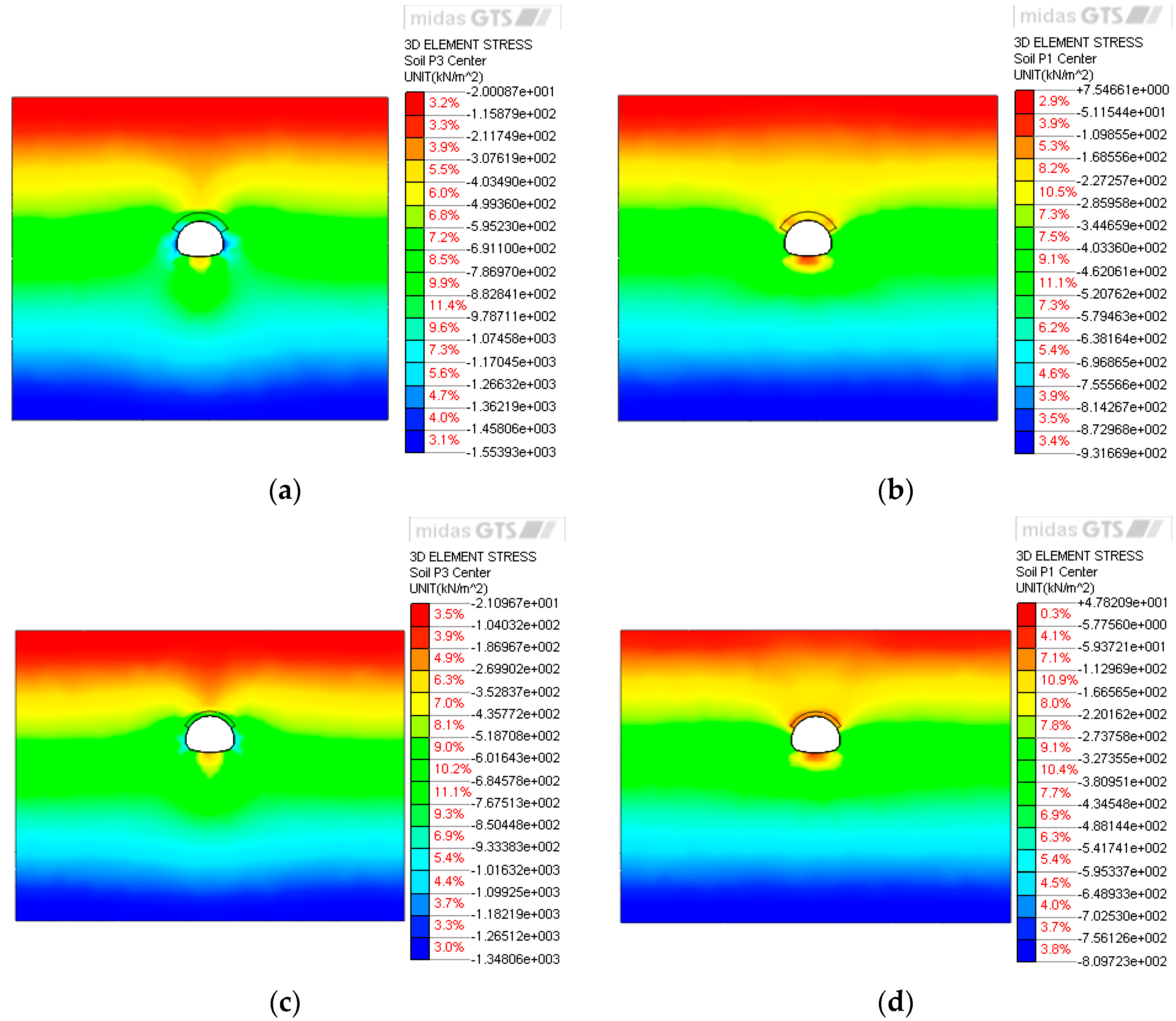
During tunnel excavation, the initial stress field in the surrounding rock is redistributed, leading to stress concentrations at key locations such as the crown, waist, foot, and invert of the tunnel. Stress variations in these regions account for more than 85% of the total stress changes in the surrounding rock. If the induced stress exceeds the strength of the rock mass during excavation and support, failure may occur. A stable stress distribution within a certain range is essential for maintaining the stability of the surrounding rock. Failure typically initiates at the periphery of the tunnel and progresses inward. After excavation, the stress distribution directly influences the deformation behavior of the support system. Based on numerical simulations, the maximum and minimum principal stresses under different cases are summarized in Table 5, and the stress distributions for Case I-1 and Case II-2 are illustrated in Figure 2.
From the stress distribution diagram, significant stress concentrations are observed during excavation at the tunnel vault, arch waist, sidewalls, arch foot, and both sides of the invert. A tensile stress zone is identified at the tunnel invert, while compressive stress dominates the sidewalls. The maximum stress occurs near the arch waist and arch foot, with notable stress variations around the vault and the lower part of the sidewalls.
Under the same pre-support condition, both the maximum and minimum principal stresses exhibit a positive correlation with the burial depth. Moreover, given the identical burial depth and surrounding rock conditions, different pre-support methods exert distinct influences on the stress distribution. When the pipe roof reinforcement method is applied, the maximum stress value is higher than that under the leading ductule method, whereas the difference in minimum stress between the two methods is marginal. This can be attributed to the larger reinforced area provided by the pipe roof method, which enables the pre-support system to withstand greater compressive stress, leading to an increase in the maximum principal stress. The analysis confirms that the pipe roof method enhances the stability of the surrounding rock more effectively, mitigating excessive stress changes during construction and reducing the risk of tunnel failure.

3.2. Plastic Zone Analysis of the Surrounding Rock

Tunnel excavation alters the stress state of the surrounding rock. After stress redistribution, if the secondary stress exceeds the compressive strength or the shear stress surpasses the shear strength, the surrounding rock enters a plastic state. Meanwhile, the initial support restricts deformation of the surrounding rock, and the contact stress between the support and the rock induces further plastic deformation.
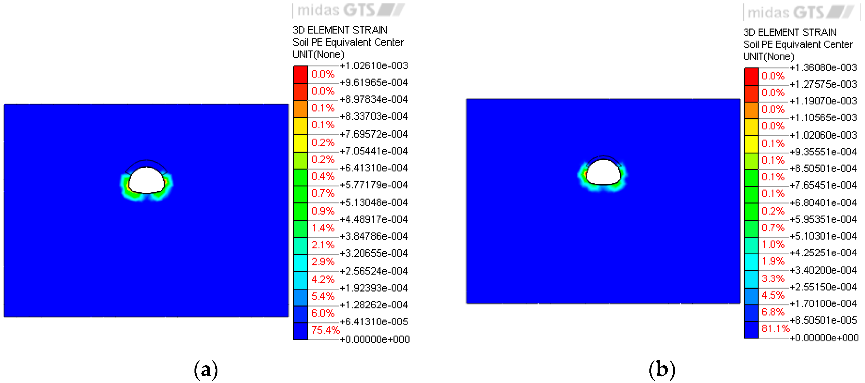
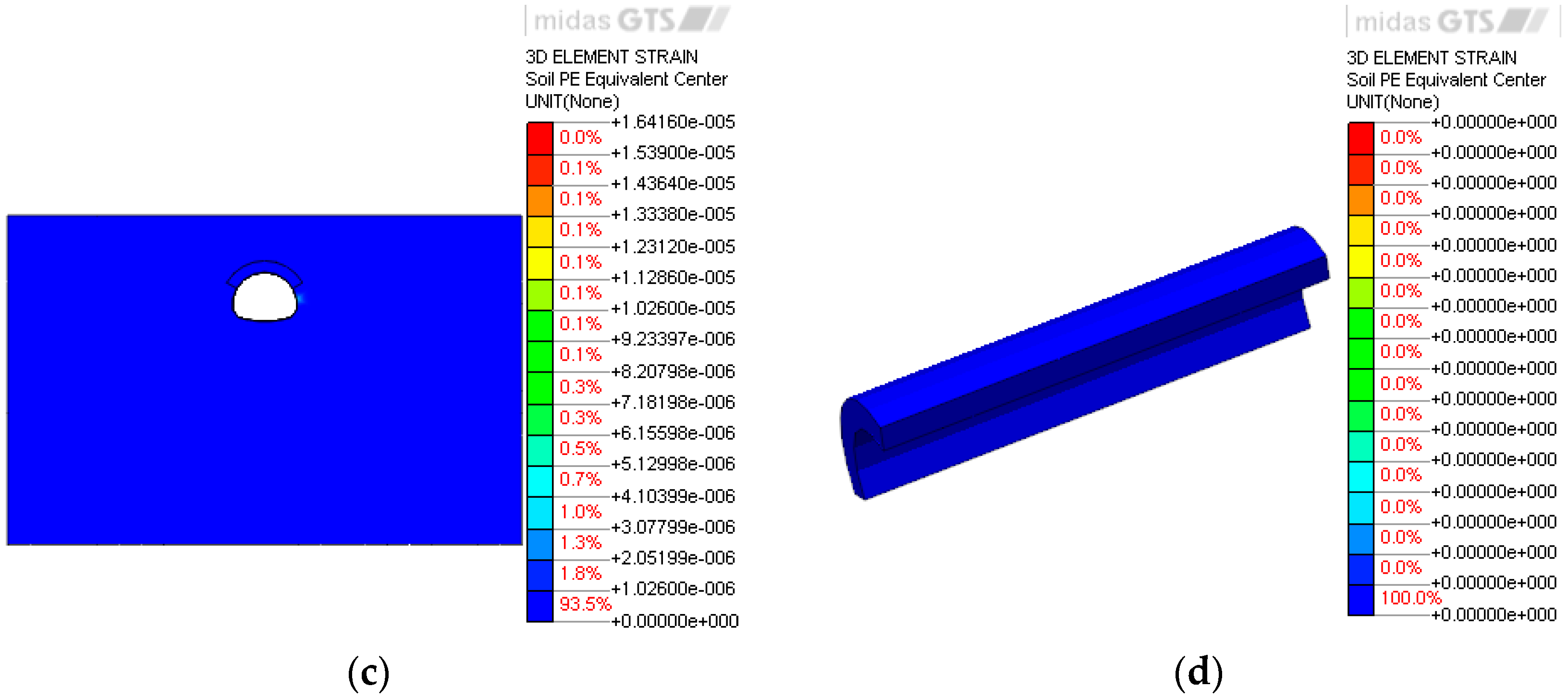
Based on the above, this study analyzes the severity and extent of plastic zones under different pre-support methods, particularly around the vault, to evaluate reinforcement effectiveness and suitable application conditions. The distribution characteristics of plastic zones are investigated, with the results illustrated in Figure 3.
During tunnel excavation, plastic zones of varying extents emerge in surrounding areas, including the vault, haunches, connections between reinforced zones and the tunnel, sidewalls, and areas near the bottom. Among these, plastic deformation is most pronounced at the sidewalls. Due to the geometric shape of the tunnel, stress concentration tends to occur at the sidewalls and near the bottom, where the maximum strain also develops. In contrast, at the tunnel vault, the presence of plastic zones is less noticeable due to reinforcement from pre-support measures.
Under the same pre-support method, the plastic zone in the surrounding rock expands as the burial depth increases—a trend particularly evident in poor rock conditions. For example, when the pipe roof pre-support method is applied in the V-grade surrounding rock, the plastic zone accounts for 11.7% of the total volume at a burial depth of 30 m. As the depth decreases to 20 m and 10 m, the proportion reduces to 9.4% and 5.1%, respectively. A similar variation trend is observed when using the leading ductule pre-support method.
Comparing the two pre-support techniques, the pipe roof method proves more effective in restraining the expansion of the plastic zone under shallow burial conditions, with only limited plasticity occurring in the reinforced areas and at the edges of the primary support connections. In contrast, the leading ductule method results in a relatively larger plastic zone within the reinforced section.

3.3. Stress Analysis of the Initial Support

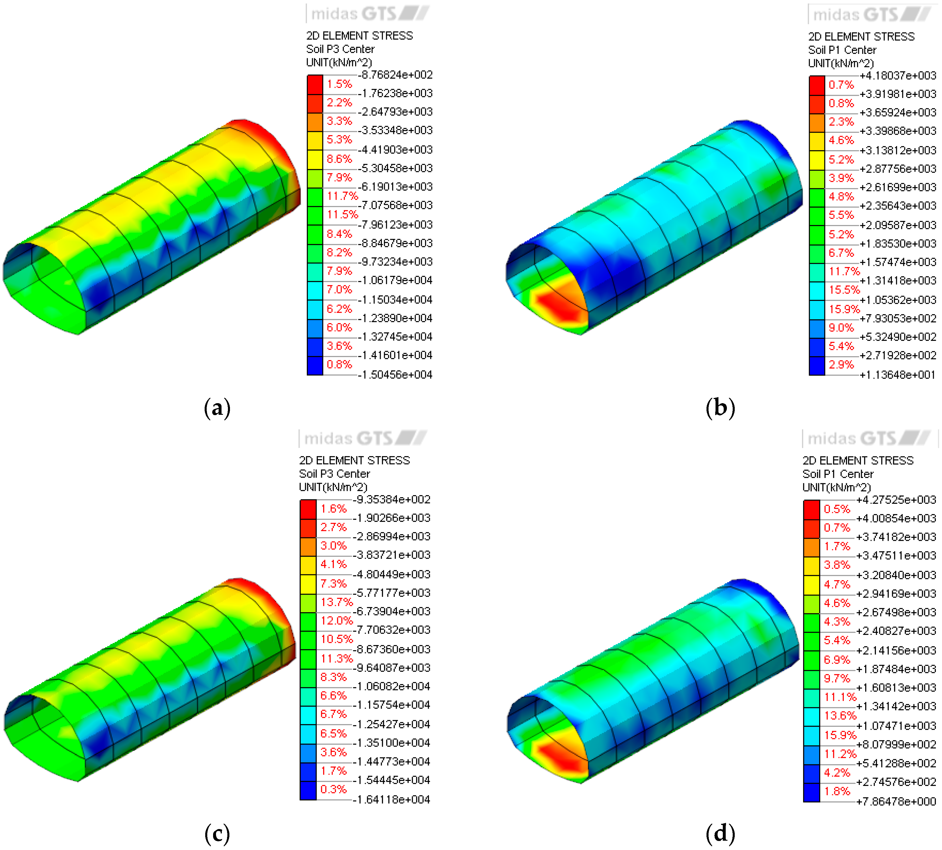
When the tunnel excavation starts, the radial stress along the surrounding rock is released to enhance its hoop stress, which applies to the initial support to cause large stress on it. In general, the concentrated compressive stress occurs in the area of the arch foot, and the tensile stress emerges at the vault and inverted arch position. Regarding this point, in this simulation, the maximum and minimum principal stresses under the different cases are analyzed. Taking Cases I-1 and I-2 as examples, the results are shown in Figure 4.
The results indicate significant stress concentrations at the tunnel vault, arch waist, sidewalls, and both sides of the invert. The maximum principal stress occurs near the junction of the arch foot with the upper and lower benches, highlighting a critical zone where compressive stress is most pronounced. A considerable tensile stress is observed at the invert. Given that the axial tensile strength of C25 concrete is 2.0 MPa, the calculated tensile stresses under various cases indicate a certain degree of structural deficiency at this location. As the burial depth increases, the tensile stress also rises, underscoring the importance of the invert in supporting the tunnel under soft rock conditions.
Under identical burial depth and rock conditions, the pipe roof reinforcement method reduces stress values at the arch waist and foot more effectively than the leading ductule method, owing to its superior capacity to restrict stress release in the surrounding rock. As shown in Figure 4 and Figure 5, the maximum principal stresses in Cases I-1 and I-2 are 15.0 MPa and 16.4 MPa, respectively, both occurring at the connection between the upper and lower benches. Since these values approach the standard axial compressive strength of C25 concrete (17 MPa), and considering construction uncertainties, the pipe roof method is recommended to enhance the safety and stability of the initial support.

3.4. Analysis of Vault Settlement Displacement

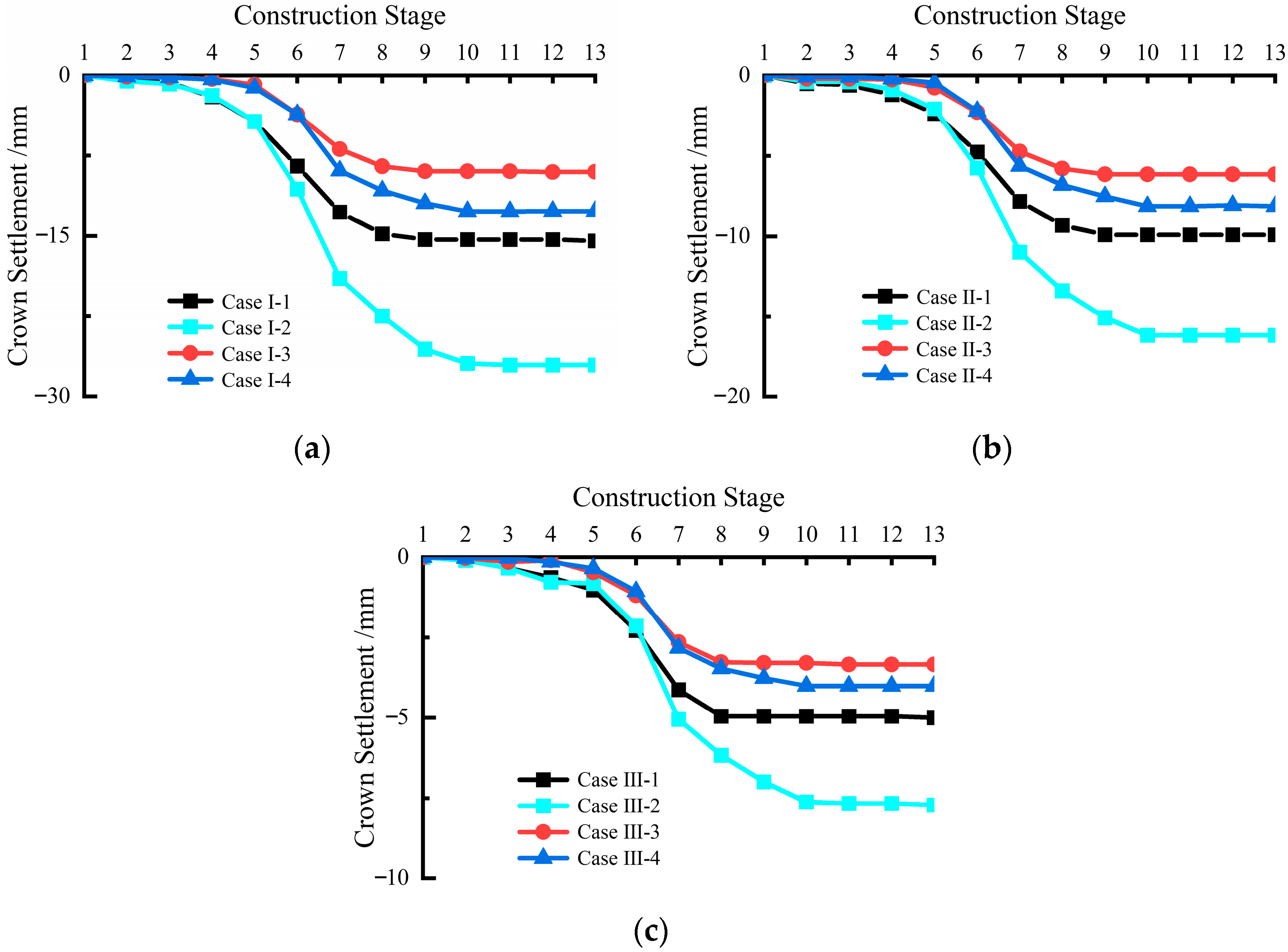
During the tunnel excavation, vertical and horizontal displacements occur in the surrounding rock due to the stress change. For the vertical displacement, it emerges in the areas above the tunnel vault and below the arch inverted position, the most obvious situation can be observed in the vault that is parallel to the tunnel axis and invert positions. The horizontal displacement is concentrated on the sidewalls on both sides of the tunnel. A monitoring section at a depth of 16 m was selected to record vault settlement displacements induced by excavation, as illustrated in Figure 5 and summarized in Table 6.
The results presented in Figure 6 and Table 6 show that the vault settlement trends under different cases are generally consistent. When the excavation face is far from the monitoring section, the settlement is negligible. As the face approaches the monitoring section, settlement begins to occur and increases rapidly, then the rate of increase slows down, eventually stabilizing. This behavior can be explained as follows: when the excavation face is far ahead, it has little influence on the monitoring section. As excavation progresses, the stress redistribution and disturbance caused by the advancing face affect the surrounding rock at the monitoring section, leading to deformation and the development of a plastic zone, which results in vault settlement. When the excavation face reaches the monitoring section, the formation of a free face significantly disturbs the surrounding rock, causing the vault settlement rate to peak. Subsequently, as excavation continues and initial support is installed, the settlement rate decreases and eventually stabilizes. Therefore, it is essential to install initial support in a timely manner after excavation to limit the excessive settlement of the surrounding rock.
Among the different cases, it can be seen that the pipe roof reinforcement method has a better effect on the prevention of the vault settlement than the leading ductule method. For example, when the burial depth is 30 m and V-grade surrounding rock, the final settlement is 15.9 mm based on the pipe roof reinforcement method, while the final settlement is 27.1 mm based on the leading ductule method. To keep the same burial depth for the IV-grade surrounding rock condition, the final settlements are, respectively, 8.8 mm and 12.3 mm for the pipe roof reinforcement method and the leading ductule method. From the abovementioned content, it can be seen that the pipe roof reinforcement method can achieve about 0.59 and 0.71 times the effects of the leading ductule method under the IV-grade and V-grade surrounding rock conditions, respectively, regarding vault settlement prevention. Therefore, under the same surrounding rock condition, the pipe roof reinforcement method shows better reinforcement efficiency than the leading ductule method, especially the V-grade surrounding rock.

3.5. The Ground Settlement Analysis

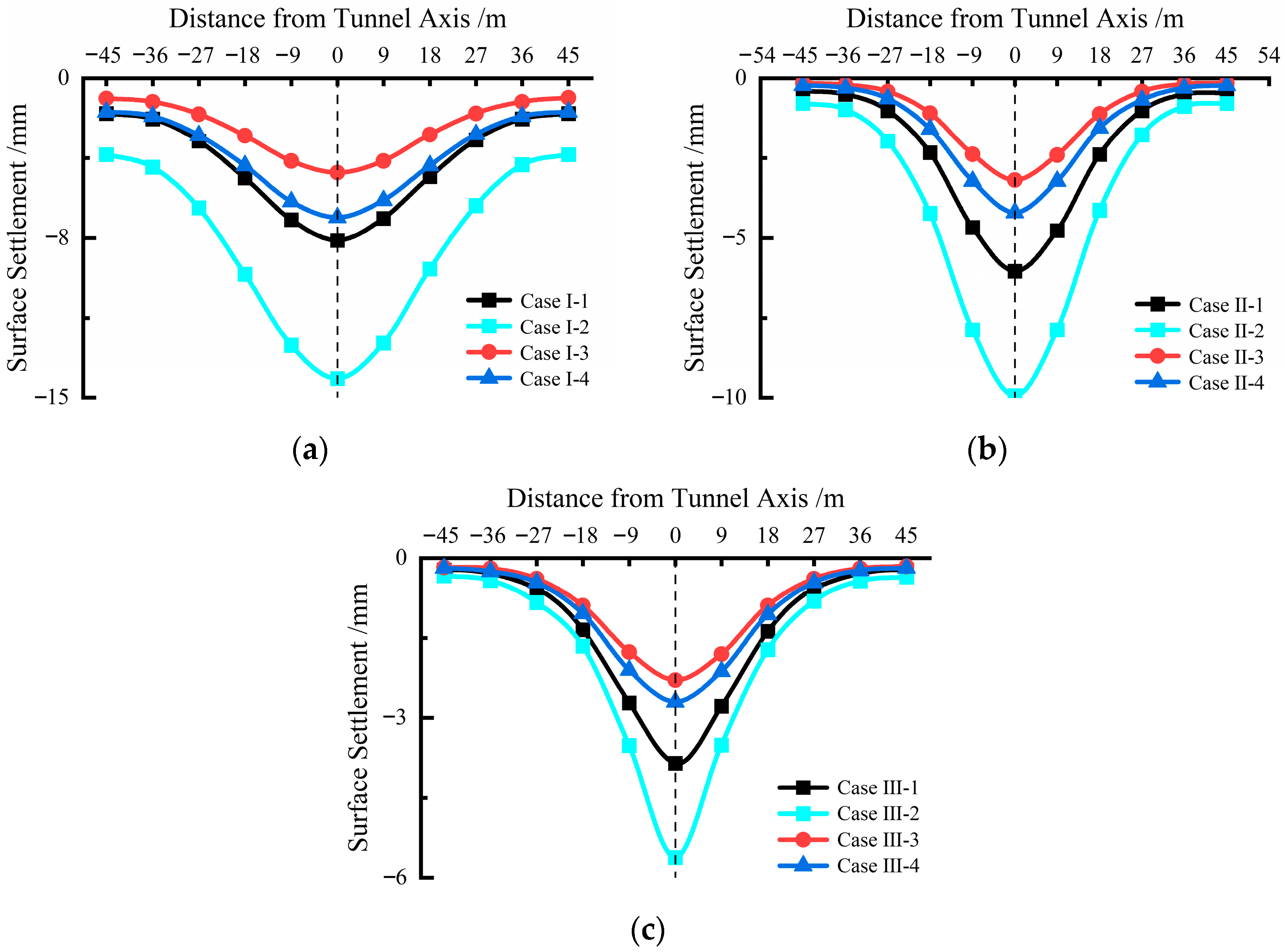
During tunnel excavation, the deformation of the surrounding rock near the tunnel gradually expands to the ground surface, resulting in the ground settlement to some degree. Regarding this point, the section of 15 m depth of the tunnel is determined to evaluate the settlement under the different cases. The analytical data of each case is extracted from the simulation and plotted in Figure 6, and the final settlements are shown in Table 7.
Based on the comprehensive analysis of Figure 7 and Table 7, it is clear that under the same surrounding rock condition, the pipe roof reinforcement method can achieve a better performance than the leading ductule method in terms of ground settlement prevention. According to the final settlements of the two methods under the different surrounding rock conditions, it can be seen that regardless of the tunnel burial depth, both of two methods can prevent the ground settlement; meanwhile, when the burial depth remains the same, the settlement when using the leading ductule method is about 1.2 times that when using the pipe roof reinforcement method, but both are within a safe range. Thus, in terms of the IV-grade surrounding rock, if there is a high limitation on the ground settlement, it is preferable to adopt the pipe roof method; otherwise, the leading ductule method can also be used. For the V-grade surrounding rock, the settlements of the pipe roof method and the leading ductule method are 7.6 mm and 14.1 mm, respectively, when the burial depth is 30 m. For the burial depth of 20 m, they are 6 mm and 9.9 mm, respectively. And for the burial depth of 10 m, they are 3.9 mm and 5.6 mm, respectively. According to the abovementioned data, it can be seen that with the burial depth increases, the settlement increasing rate based on the pipe roof method is lower than the leading ductule method, which means the pipe roof method has an obvious performance on the ground settlement prevention. To summarize, in terms of deep burial depth and the poor surrounding rock condition, it is preferable to adopt the pipe roof reinforcement method.

4. Engineering Applications

Based on the on-site topographic and geological conditions, the portal section of Huashan Tunnel was constructed using the pipe roof method for pre-support and the bench cut method for excavation, steel arch support, and composite lining. This approach is essentially consistent with the pre-support and excavation methods adopted in the numerical simulation.

4.1. Pre-Support Arrangements

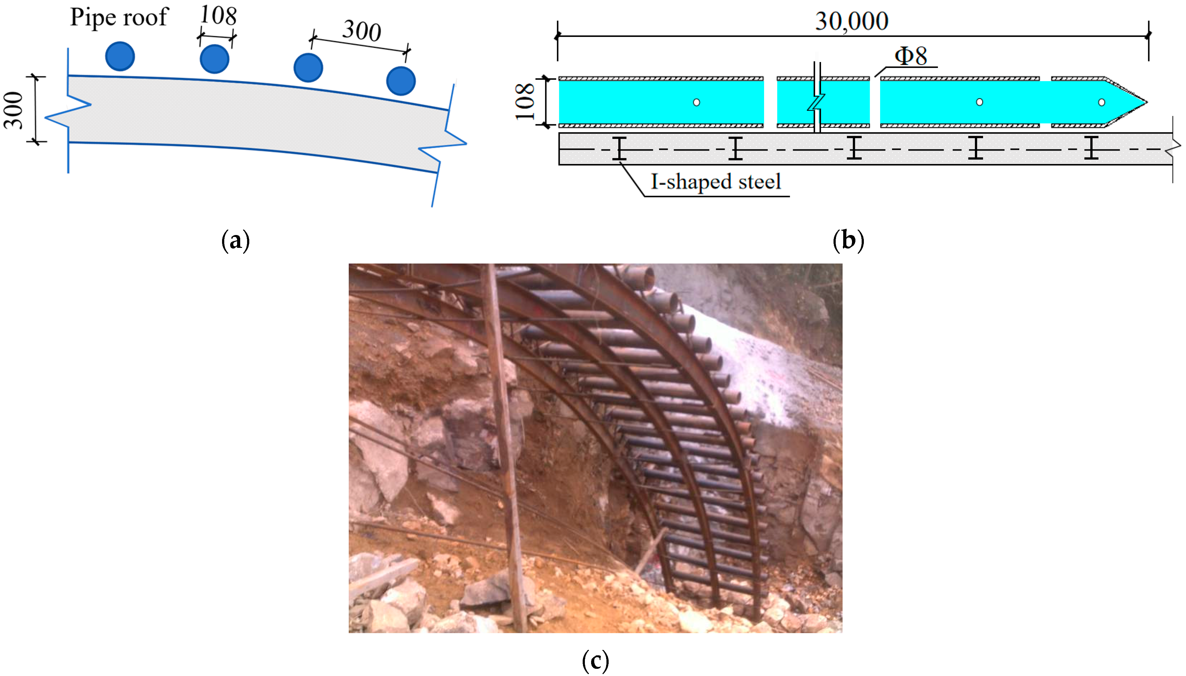
The portal section of the tunnel was constructed using hot-rolled seamless steel pipes with a specification of Φ108 × 9 mm. Grouting holes with diameters of 6–8 mm were drilled at 30 cm intervals along the pipe wall, arranged in four rows. Each pipe had a total length of 30 m and was installed at a spacing of 30 cm with an outward inclination angle of 1°. The overlapping length between adjacent longitudinal pipe sections was 3 m, and the pipes were arranged in a semicircular dense formation outside the excavation contour line at a distance of 0.3 m. Pipe roofs were combined with grouting, with a grouting pressure of 0.5–2.0 MPa.

4.2. Field Monitoring and Result Analysis

4.2.1. Monitoring Point Layout

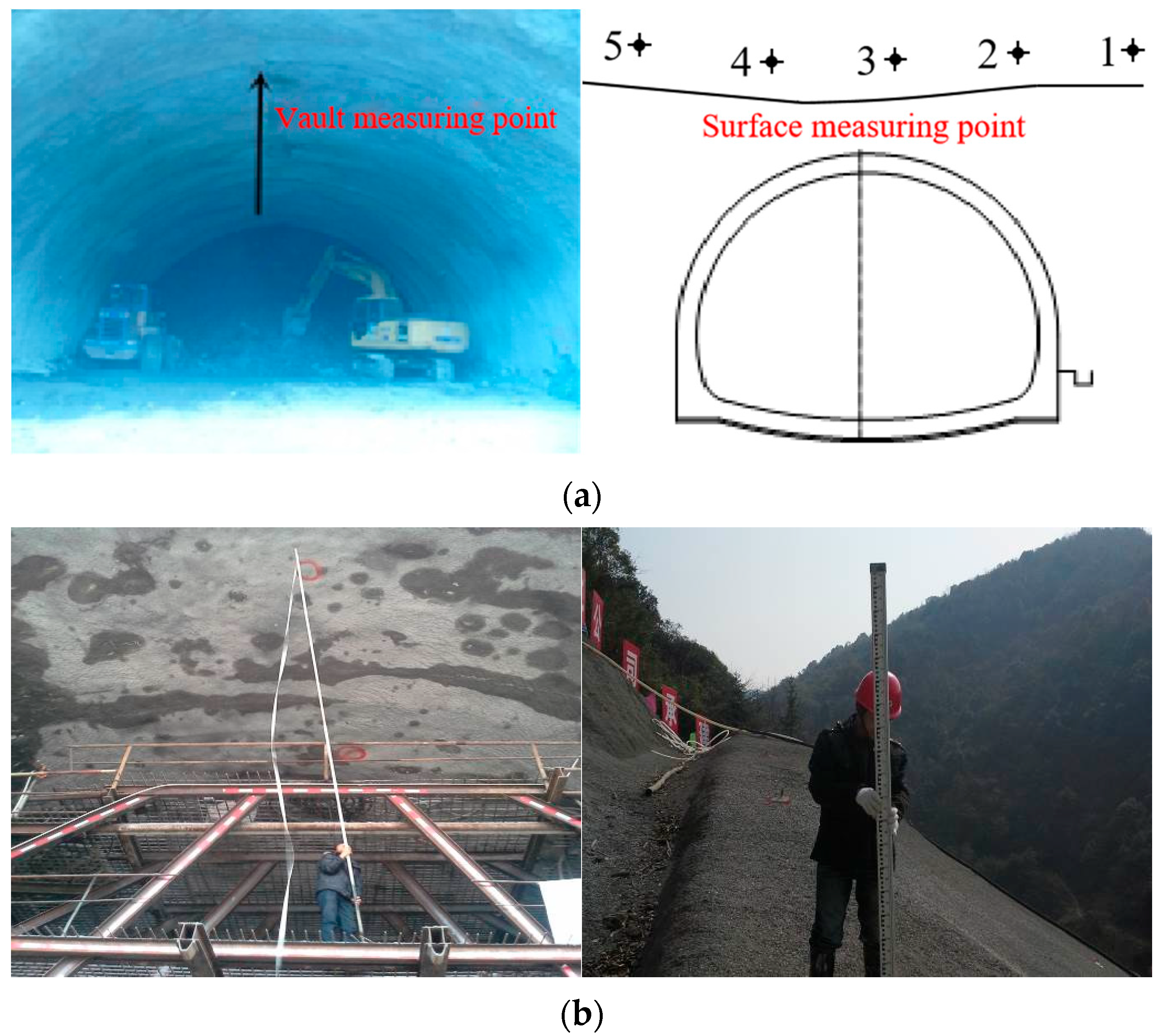
To monitor the deformation of the surrounding rock, monitoring points are strategically placed on both the vault and the ground surface of the tunnel. The measuring points are arranged as shown in Figure 8. Monitoring points were installed at YK10+274 for the vault settlement and at YK10+280 for the surface settlement to measure the deformation of the surrounding rock.

4.2.2. Result Analysis

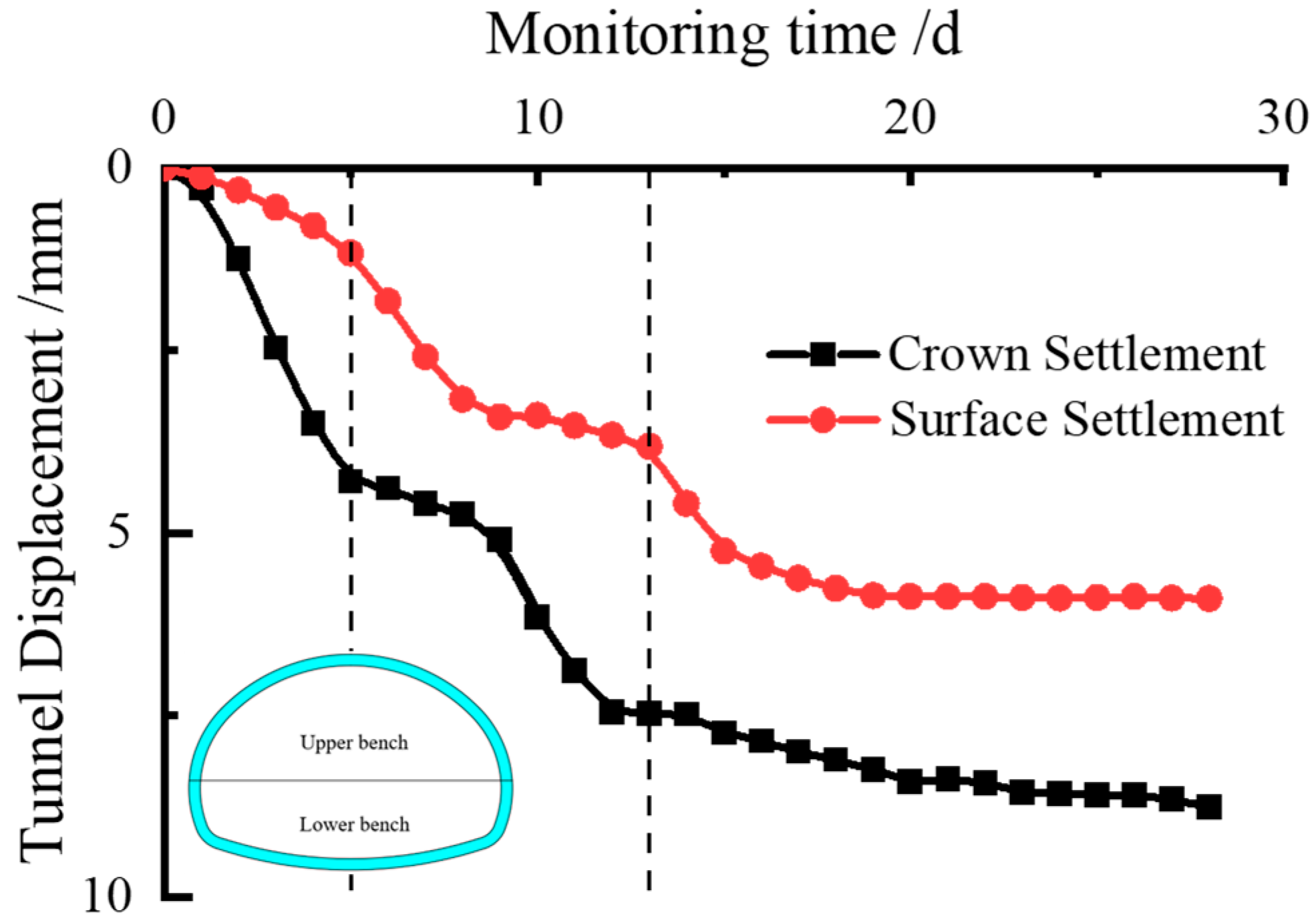
The crown settlement data from the YK10+274 section and the surface settlement data from the YK10+280 section, which were continuously monitored for 28 days until stabilization was achieved, were selected to demonstrate the typical tunnel displacement characteristics. The summarized monitoring data are shown in Figure 9 and Table 8.
(1)
During tunnel excavation, the crown settlement rate is closely related to the face position. When the upper bench face reached the monitoring section, the crown settlement rate increased significantly. As the face advanced further, the rate gradually decreased. The settlement rate peaked again when the lower bench face passed through, accompanied by a minor increase in settlement, before eventually stabilizing. The final crown settlement at this section was 8.76 mm. The numerical simulation results were slightly higher than the measured values, primarily due to the simplified assumption of horizontally homogeneous material for the surrounding rock in the numerical model, which did not fully account for the actual stratified ground and topographic variations.
(2)
The surface settlement trend was generally consistent with the crown settlement. The monitoring section YK10+280, located 10 m from the tunnel portal, exhibited minor settlement during the initial excavation phase due to construction disturbance. The settlement rate increased as the upper bench face approached the section, and a significant abrupt change occurred when the lower bench passed through. The final stabilized settlement value was 5.902 mm. As this point was directly above the tunnel, it experienced the maximum settlement. The numerical simulation results were slightly higher than the field measurements for the same reason mentioned above. Although blasting and construction activities caused some interference, the overall development of the settlement remained controllable under the effect of pipe roof pre-support, and the trend aligned well with the simulation results.
(3)
The pipe roof pre-support method significantly suppressed both crown and surface settlements. No major abrupt changes occurred throughout the excavation process, demonstrating that this technique effectively controls tunnel deformation and ensures subsequent construction safety.
In summary, the numerical simulation results generally agreed with the field monitoring data, demonstrating that the numerical method can serve as a reliable reference for predicting and controlling tunnel construction.

5. Conclusions

In this paper, the finite element simulation is adopted to model a tunnel excavation project; the different pre-support technologies, including the pipe roof reinforcement method and the leading ductule method, have been investigated to evaluate their support effectiveness. The analytical results, including the stress, plastic zone, vault settlement, and the ground settlement, are obtained and discussed. Based on the obtained results, there are several conclusions that can be drawn as follows:
(1)
Under greater burial depths, the maximum principal stress in the surrounding rock within the pipe roof reinforced zone is significantly higher than that observed with the leading ductule reinforcement. In contrast, under shallow burial conditions, the stress levels between the two methods are comparable. The plastic zone is primarily distributed in areas including the vault, arch waist, interface between the reinforced zone and the tunnel, sidewalls, and floor, exhibiting non-uniform thickness characteristics. Under shallow burial conditions, both pre-support methods effectively suppress the development of the plastic zone. These structures contribute to the stress redistribution of the surrounding rock and bear part of the external load, thereby reducing the compressive stress on the initial support and improving its mechanical state.
(2)
Despite its higher cost and more complex construction process, the pipe roof pre-support method demonstrates significant advantages in controlling the stress release and deformation of the surrounding rock due to its superior stiffness and larger reinforcement zone. It is particularly effective in preventing instability or structural failure under conditions of deep burial and weak surrounding rock. This method outperforms leading ductule pre-support in constraining the plastic zone and sharing the surrounding rock pressure, exhibiting a greater capacity to withstand high stress and demonstrating stronger adaptability and reliability in complex geological conditions.
(3)
Field monitoring demonstrated that the pipe roof pre-support effectively controlled the crown settlement within a safe range until it eventually stabilized. During construction, blasting and excavation activities induced certain surface settlements in the shallowly buried section; however, under the support of the pipe roof structure, surface deformation remained within acceptable limits and ultimately stabilized. The numerical simulation results showed good agreement with field measurements. Affected by the assumptions of the computational model, the simulated values were slightly higher than the measured data, indicating that the numerical method can effectively predict the deformation behavior of the surrounding rock induced by tunnel excavation. The simulation approach offers practical guidance for construction, and the conclusions of the study are considered reliable.

Author Contributions

Conceptualization, Y.J. and H.L. (Hui Liu).; methodology H.L. (Hao Luo).; validation, H.L. (Hui Liu). and J.G.; formal analysis, Y.J.; investigation, H.L. (Hui Liu).; resources, H.L. (Hui Liu).; data curation, Y.J.; writing—original draft preparation, Y.J. and H.L. (Hao Luo).; writing—review and editing, Y.J., H.L. (Hao Luo)., H.L. (Hui Liu). and J.G.; visualization, H.L. (Hui Liu).; supervision, H.L. (Hao Luo). and J.G.; project administration, Y.J.; funding acquisition, H.L. (Hui Liu). All authors have read and agreed to the published version of the manuscript.

Funding

This study was supported by the National Natural Science Foundation of China (52308373). The authors wish to express their gratitude to Wuhan Institute of Technology for financial support for this research.

Data Availability Statement

The original contributions presented in this study are included in the article. Further inquiries can be directed to the corresponding author.

Conflicts of Interest

Author Yunpeng Jiang was employed by Ningbo Highway Municipal Design Co., Ltd. The remaining authors declare that the research was conducted in the absence of any commercial or financial relationships that could be construed as a potential conflict of interest.

References

  1. Hisatake, M.; Ohno, S. Effects of pipe roof supports and the excavation method on the displacements above a tunnel face. Tunn. Undergr. Space Technol. 2008, 23, 120–127. [Google Scholar] [CrossRef]
  2. Zhang, Z.Q.; Li, H.Y.; Liu, H.Y.; Li, G.; Shi, X. Load transferring mechanism of pipe umbrella support in shallow-buried tunnels. Tunn. Undergr. Space Technol. 2014, 43, 213–221. [Google Scholar] [CrossRef]
  3. Yang, S.; Wang, M.; Du, J.; Guo, Y.; Geng, Y.; Li, T. Research of jacking force of densely arranged pipe jacks process in pipe-roof pre-construction method. Tunn. Undergr. Space Technol. 2020, 97, 103277. [Google Scholar] [CrossRef]
  4. Zarei, H.; Moarefvand, P.; Salmi, E.F. Numerical modeling of umbrella arch technique to reduce tunnelling induced ground movements. Environ. Earth Sci. 2019, 78, 291. [Google Scholar] [CrossRef]
  5. Gong, L.; Feng, J.; Zhou, P.; Sun, D.; Zhou, F.; Hu, H.; Wang, L. Study on bearing failure characteristics and parameters of pipe roof support in super shallow buried tunnel in soft surrounding rock. Tunn. Undergr. Space Technol. 2023, 140, 105283. [Google Scholar] [CrossRef]
  6. Yang, C.; Chen, Y.; Huang, D.; Wang, L. Arching effect between the pipes of a pipe umbrella support system in a shallow-buried tunnel. KSCE J. Civ. Eng. 2019, 23, 5215–5225. [Google Scholar] [CrossRef]
  7. Kim, J.; Kim, J.; Rehman, H.; Yoo, H. Ground Stability Analysis in Non-Open-Cut Tunneling Method Using Small-Diameter Steel Pipe Piles. Appl. Sci. 2020, 10, 6906. [Google Scholar] [CrossRef]
  8. Oke, J.; Vlachopoulos, N.; Diederichs, M.S. Improved input parameters and numerical analysis techniques for temporary support of underground excavations in weak rock. In Proceedings of the RockEng12, 21st Canadian Rock Mechanics Symposium, Edmonton, AB, Canada, 5–9 May 2012. [Google Scholar]
  9. Xiao, J.Z.; Dai, F.C.; Wei, Y.Q.; Xing, Y.C.; Cai, H.; Xu, C. Analysis of mechanical behavior in a pipe roof during excavation of a shallow bias tunnel in loose deposits. Environ. Earth Sci. 2016, 75, 293. [Google Scholar] [CrossRef]
  10. Li, Y.; Wang, W.; Yan, S.; Du, J. Theoretical Analysis on the Effectiveness of Pipe Roofs in Shallow Tunnels. Appl. Sci. 2022, 12, 9106. [Google Scholar] [CrossRef]
  11. Xiao, H.; Zhou, S.; Sun, Y. Stability Analysis and Case Study of Shallow Tunnel Using Pipe Roof Support. Geotech. Geol. Eng. 2019, 37, 1249–1260. [Google Scholar] [CrossRef]
  12. Liu, D.; Zhang, D.; Fang, Q.; Sun, Z.; Cao, L.; Li, A. Displacement Characteristics of Shallow-Buried Large-Section Loess Tunnel with Different Types of Pre-Supports: A Case Study of New Badaling Tunnel. Appl. Sci. 2019, 10, 195. [Google Scholar] [CrossRef]
  13. Huang, F.; Wu, C.; Jang, B.A.; Hong, Y.; Guo, N.; Guo, W. Instability mechanism of shallow tunnel in soft rock subjected to surcharge loads. Tunn. Undergr. Space Technol. 2020, 99, 103350. [Google Scholar] [CrossRef]
  14. Sun, Z.; Zhang, D.; Liu, D.; Tai, Q.; Hou, Y. Insights into the ground response characteristics of shallow tunnels with large cross-section using different pre-supports. Int. J. Rock Mech. Min. Sci. 2024, 175, 105663. [Google Scholar] [CrossRef]
  15. Bai, C.; Xue, Y.; Qiu, D.; Su, M.; Ma, X.; Liu, H. Analysis of factors affecting the deformation of soft rock tunnels by data envelopment analysis and a risk assessment model. Tunn. Undergr. Space Technol. 2021, 116, 104111. [Google Scholar] [CrossRef]
  16. Hu, M.; Zhang, Y.; Xu, W.; Wang, H.; Wang, R.; Yang, X.; Ma, J.; Huang, W. Large Deformations and Numerical Analysis of a Typical Soft Rock Tunnel in the Chuxiong Section of the Yunnan Central Water Diversion Project. Int. J. Geomech. 2024, 24, 05024002. [Google Scholar] [CrossRef]
  17. Liu, K.; Li, S.; Ding, W.; Hou, M.; Gong, Y.; Li, H. Pre-supporting mechanism and supporting scheme design for advanced small pipes in the silty clay layer. Tunn. Undergr. Space Technol. 2020, 98, 103259. [Google Scholar] [CrossRef]
  18. Zhang, C.; Zhang, Q.; Pei, Z.; Song, Z.; Wang, J. Construction sequence optimization and settlement control countermeasures of metro tunnels underpassing expressway. Adv. Civ. Eng. 2021, 2021, 8834368. [Google Scholar] [CrossRef]
  19. An, Y.L.; Zhou, J.; Ouyang, P.B.; Li, J.H. Analysis of tunnel face stability with advanced pipes support. J. Cent. South Univ. 2021, 28, 604–617. [Google Scholar] [CrossRef]
  20. Ma, P.; Shimada, H.; Sasaoka, T.; Hamanaka, A.; Dintwe, T.K.M.; Pan, D. Investigation on the Performance of Pipe Roof Method Adjacent to the Underground Construction. Geotech. Geol. Eng. 2021, 39, 4677–4687. [Google Scholar] [CrossRef]
  21. Zhang, Y.; Zhao, X.; Guo, F.; Tao, L.; Liu, J.; Liao, W.; Tan, L.; Yang, X. Influence of the Advance Jacked Pipe on the Jacking Force of the Subsequent Pipe Based on Pipe–Soil Full Contact Model. Lithosphere 2024, 2024, lithosphere_2023_216. [Google Scholar] [CrossRef]
  22. Zhang, X.; Zhang, D.; Rong, Y.; Ma, Y.; Yao, C.; Sun, Y. Study on the stability of tunnel in weak surrounding rock considering initial support parameters and excavation method. KSCE J. Civ. Eng. 2024, 28, 2427–2439. [Google Scholar] [CrossRef]
  23. Liu, X.J.; Zhang, Y.X.; Gao, S.J.; Huang, D.; Yang, C. Mechanism analysis and treatment technique of surrounding rock instability for tunnel portal section in weak surrounding rock. Rock. Soil. Mech. 2012, 33, 2229–2234. [Google Scholar]
  24. Qiu, W.; Kong, C.; Liu, K. Three-Dimensional Numerical Analysis of the Tunnel for Polyaxial State of Stress. Math. Probl. Eng. 2015, 2015, 301241. [Google Scholar] [CrossRef]
  25. Do, N.A.; Dias, D.; Oreste, P.; Djeran-Maigre, I. 2D numerical investigation of segmental tunnel lining behavior. Tunn. Undergr. Space Technol. 2013, 37, 115–127. [Google Scholar] [CrossRef]
  26. Zaid, M.; Mishra, S. Numerical analysis of shallow tunnels under static loading: A finite element approach. Geotech. Geol. Eng. 2021, 39, 2581–2607. [Google Scholar] [CrossRef]
  27. Yen, J.; Shou, K. Numerical simulation for the estimation the jacking force of pipe jacking. Tunn. Undergr. Space Technol. 2015, 49, 218–229. [Google Scholar] [CrossRef]
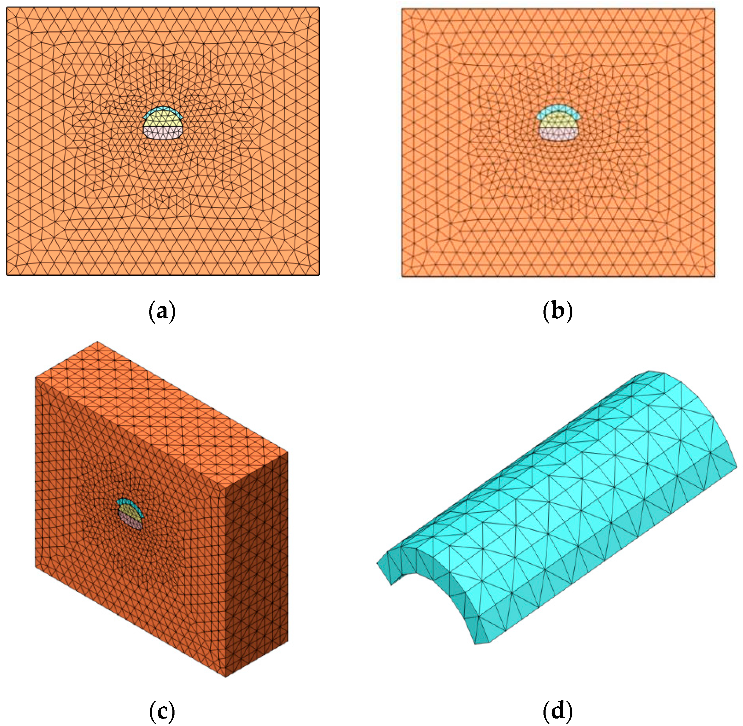
Figure 1. (a) The model with leading ductule reinforcement method; (b) the model with pipe roof reinforcement method; (c) the overall finite element model; and (d) the reinforcement area model.
Buildings 15 03791 g001
Figure 2. Stress of the surrounding rock under the different cases. (a) Case I-1 maximum principal. (b) Case I-1 minimum principal. (c) Case II-2 maximum principal. (d) Case II-2 minimum principal.
Buildings 15 03791 g002
Figure 3. Plastic zone size and distribution under the different cases. (a) Case II-1. (b) Case II-2. (c) Case III-3. (d) Case III-3.
Buildings 15 03791 g003aBuildings 15 03791 g003b
Figure 4. Stress of the initial support under the different cases. (a) Case I-1 maximum principal. (b) Case I-1 minimum principal. (c) Case I-2 maximum principal. (d) Case I-2 minimum principal.
Buildings 15 03791 g004
Figure 5. The settlement displacement at the monitoring section of the vault. (a) Case I-1~I-4. (b) Case II-1~II-4. (c) Case III-1~III-4.
Buildings 15 03791 g005
Figure 6. The ground settlement of the monitoring section. (a) Case I-1~I-4. (b) Case II-1~II-4. (c) Case III-1~III-4.
Buildings 15 03791 g006
Figure 7. Schematic image of the pipe roof (unit: mm): (a) cross-section; (b) longitudinal section; and (c) installation of on-site pipe shields.
Buildings 15 03791 g007
Figure 8. Measuring point layout: (a) measuring point layout; (b) on-site monitoring.
Buildings 15 03791 g008
Figure 9. Tunnel displacement–time.
Buildings 15 03791 g009
Table 1. The material properties of the rock bolt.
ComponentElastic Modulus (kN/m2)Poisson’s Ratio μUnit Weight
γ (kN/m3)
Diameter
D (m)
rock bolt2.1 × 1070.2780.025
Table 2. The material properties of the surrounding rock and sprayed concrete.
ItemIV Surrounding RockV Surrounding RockReinforcement AreaSoft ShotcreteHard Shotcrete
TypeSolidSolidSolidPlanePlane
Elastic modulus (kN/m2)1 × 1065 × 1053 × 1061.5 × 1072.3 × 107
Poisson’s ratio μ0.350.380.280.20.2
Unit weight
γ (kN/m3)
2220242323
Cohesion C (kN/m2)15050300--
Internal friction angle φ (°)282535--
Table 3. Analysis cases for finite element simulation.
ItemBurial DepthsSurrounding Rock GradeReinforcement Method
Case ICase I-130 mVP-S
Case I-230 mVSTGI
Case I-330 mIVP-S
Case I-430 mIVSTGI
Case IICase II-120 mVP-S
Case II-220 mVSTGI
Case II-320 mIVP-S
Case II-420 mIVSTGI
Case IIICase III-110 mVP-S
Case III-210 mVSTGI
Case III-310 mIVP-S
Case III-410 mIVSTGI
Note. P-S: pipe roof pre-support technology; STGI = leading ductule pre-support technology.
Table 4. The excavation procedures simulation.
ProcedureConstruction DescriptionProcedureConstruction Description
1The initial stress definition8To excavate upper step 6 and bottom step 5
2The advanced reinforcement area hardening9To excavate upper step 7 and bottom step 6
3To excavate upper step 110To excavate upper step 8 and bottom step 7
4To excavate upper step 2 and bottom step 111To excavate bottom step 8
5To excavate upper step 3 and bottom step 212Spraying the concrete on step 8
6To excavate upper step 4 and bottom step 313Hardening the sprayed concrete
7To excavate upper step 5 and bottom step 4
Table 5. The maximum and minimum principal stress values of the surrounding rock under the different cases.
CaseMaximum Principal Stress (MPa)Minimum Principal Stress (MPa)CaseMaximum Principal Stress (MPa)Minimum Principal Stress (MPa)
Case I-1−1.434−0.328Case II-3−1.078−0.158
Case I-2−1.165−0.338Case II-4−1.022−0.143
Case I-3−1.553−0.311Case II-1−0.628−0.068
Case I-4−1.49−0.186Case III-2−0.595−0.082
Case II-1−1.017−0.229Case III-3−0.644−0.058
Case II-2−0.977−0.147Case III-4−0.608−0.078
Table 6. The final settlement displacement at the monitoring section of the vault under the different cases.
CaseSettlement Displacement (mm)CaseSettlement Displacement (mm)
Case I-115.9Case II-35.8
Case I-227.1Case II-48.1
Case I-38.8Case III-14.6
Case I-412.3Case III-27.9
Case II-19.8Case III-33
Case II-216.2Case III-44.2
Table 7. The final settlement displacement of the monitoring section under the different cases.
CaseSettlement Displacement (mm)CaseSettlement Displacement (mm)
Case I-17.6Case II-33.2
Case I-214.1Case II-44.2
Case I-34.4Case III-13.9
Case I-46.5Case III-25.6
Case II-16Case III-32.3
Case II-29.9Case III-42.7
Table 8. The final settlement displacement of the monitoring section.
Monitoring
Section
Crown Settlement Displacement (mm)Monitoring
Section
Surface Settlement Displacement (mm)
YK10+2748.76YK10+2805.902
Disclaimer/Publisher’s Note: The statements, opinions and data contained in all publications are solely those of the individual author(s) and contributor(s) and not of MDPI and/or the editor(s). MDPI and/or the editor(s) disclaim responsibility for any injury to people or property resulting from any ideas, methods, instructions or products referred to in the content.