Article

Dynamic Response Analysis of Infilled RC Frames with Openings Under Instantaneous Column Removal Scenarios

1
Guangxi Key Laboratory of Green Building Materials and Construction Industrialization, Guilin 541004, China
2
College of Civil Engineering and Geomatics, Guilin University of Technology at Nanning, Nanning 530001, China
3
School of Civil Engineering, Guilin University of Technology, Guilin 541004, China
4
College of Earth Sciences, Guilin University of Technology, Guilin 541004, China
*
Author to whom correspondence should be addressed.
Buildings 2025, 15(20), 3778; https://doi.org/10.3390/buildings15203778
Submission received: 21 September 2025 / Revised: 13 October 2025 / Accepted: 16 October 2025 / Published: 20 October 2025
(This article belongs to the Section Building Structures)

Abstract

In order to further explore the role of infill walls in the progressive collapse resistance of reinforced concrete (RC) spatial frames, based on ANSYS/LS-DYNA finite element analysis software, the refined numerical models of pure RC spatial frames and infilled RC spatial frames were constructed, respectively. By comparing it with the experimental results, the validity and accuracy of the model are verified. Subsequently, the effects of column removal devices and infill wall openings on the progressive collapse resistance of RC spatial frames were studied. The results show that the residual displacement of the model with a complete column removal device is 238.1% higher than that of the model with an incomplete column removal device, and the stiffness is reduced by 68.8%. The results obtained by an incomplete column removal device are often unsafe. The open-hole infill wall will form a diagonal strut in the corresponding area. The strength of the strut near the fixed end has the most significant effect on the structural stiffness after the column is removed and plays a controlling role. The reduction in the effective area of the strut reduces the strength of the strut and weakens the structural stiffness. When the opening is arranged in the mid-span position, the structural stiffness decreases more significantly.

1. Introduction

Building structures under the action of fire, impact, explosion, and other occasional extreme loads may experience local damage [1], which can lead to the overall structure’s progressive collapse [2], resulting in a threat to people’s lives and property losses. The explosion of the Ronan Point apartment in 1968 first attracted the attention of engineering and academic circles to the problem of progressive collapse [3]. Following that initial research, through extensive experiments and theoretical analyses, researchers have systematically grasped the causes of progressive collapse, its analysis methods, and design approaches.
Marjanishvili [4] proposed four analytical methods for assessing the risk of the progressive collapse of structures—linear and nonlinear static analysis methods and linear and nonlinear dynamic analysis methods—and compared their advantages and disadvantages. Yu et al. [5] put forward a theoretical approach that can calculate the whole process of the pressurized arch mechanism. This evaluates the influence of boundary conditions by introducing two indicators, axial stiffness and rotational stiffness. Kang et al. [6] proposed a theoretical calculation model of a compression arch mechanism, which can more realistically reflect the reinforcement in a state of stress. Early work by Yi et al. [7] on the suspension mechanism considered full beam reinforcement but was limited to concentrated loads, a constraint addressed by Qian et al. [8] in their extended model incorporating uniform load effects. Beyond in situ tests [9,10], laboratory studies on substructures and scaled models have been prevalent. Dynamic tests by Qian et al. [11] and static tests by Yu et al. [12] on scaled specimens have quantified the influence of design span and slab action on collapse resistance. Ma et al. [13] demonstrated that the force mechanism is largely unchanged for different column removal scenarios in slab-column systems. Ultimately, the full-scale test by Adam et al. [14] confirmed that catenary action, enabled by robust load redistribution, is a principal resistance mechanism in real-scale structures following column loss. Sasani et al. [15] proposed a finite element modelling and analysis method of the RC element, considering steel bar fracture, and the analysis results showed that this modelling method was able to develop the suspension chain line mechanism, and identified and explained the root cause of the decrease in the vertical resistance of the beams after the peak force. Pham et al. [16] and Qian et al. [17] investigated the effect of different loading methods on the resistance mechanism of the RC beam–slab substructures against the progressive collapse, under the failure conditions of the inner columns and the corner columns, based on LS-DYNA. The study showed that the two loading methods produced significantly different damage modes, and the UDL method (uniform load loading method) could achieve a more uniform deformation of beams and slabs. Tsai et al. [18] carried out numerical simulations of finite element models for three different types of openings in infill walls with equal opening rates, and found that wing-type openings had the most favourable effect on the performance of the structure against successive collapses. Kong et al. [19] conducted a finite element modelling of the steel-reinforced, concrete, fully infill wall frames to develop a refined finite element model, and the analysis results showed that the preloaded out-of-face loads changed the in-face damage mode of infill wall RC frames and reduced the in-face strength of infill wall RC frames.
As non-load-bearing components in frame structures, infill walls are typically considered only for their self-weight in practical design, while their load-bearing contributions are often neglected. However, due to their inherent strength and stiffness, infill walls frequently interact with the primary frame, sharing a portion of the applied loads. While the influence of infill walls on seismic performance has been widely recognized, their role in progressive collapse scenarios remains insufficiently systematically investigated [20,21]. Previous studies have demonstrated that infill walls can form alternative load paths during collapse, significantly enhancing initial stiffness, collapse resistance capacity, and overall safety margins [22,23]. Consequently, their effects warrant careful consideration in progressive collapse analysis. For instance, Shan et al. [24] conducted tests on two-story, two-bay RC frames with infill walls under a middle-column removal scenario, revealing that the infill walls acted as struts during the initial, compressive arching, and catenary stages. This altered the strain distribution in beam reinforcements, load transfer mechanisms, and failure modes, with initial stiffness reaching 162% of that in bare frames. Similarly, Baghi et al. [25] reported that in single-story, single-bay infilled frames, the initial stiffness, ultimate load capacity, and corresponding displacement were approximately 500%, 220%, and 270% of those in bare frames, respectively.
Despite these findings highlighting the beneficial role of infill walls in mitigating progressive collapse, existing experimental studies are predominantly limited to simple components or scaled models [26]. A systematic understanding of the collaborative mechanisms between infill walls and full-scale frame structures, particularly the impact of wall openings, remains elusive. To address this gap, this study employs ANSYS/LS-DYNA to develop a finite element model of a two-story, two-bay, full-scale RC frame structure. The model simulates the progressive collapse process under instantaneous column loss conditions, aiming to systematically investigate the influence of infill walls on the dynamic response and failure mechanisms of the frame. Furthermore, the study introduces opening parameters in the infill walls to analyze how variations in opening size and location affect collapse resistance, load paths, and deformation patterns. This work provides original insights by critically evaluating the often-overlooked effect of column removal devices and systematically deciphering the controlling role of diagonal struts in open infill walls. The findings are expected to provide comprehensive insights for the anti-collapse design of practical engineering structures.

2. Finite Element Modelling and Validation

2.1. General Situation

2.1.1. Test Introduction

This study develops and validates a finite element model based on the progressive collapse tests by Adam et al. [14] and Buitrago et al. [27] on full-scale pure RC frame structures and infill wall RC structures subjected to corner column removal. The study investigates a full-scale two-story reinforced concrete frame structure with a column grid of 5 m × 5 m and a story height of 2.8 m. The specimen features a 200 mm thick flat slab, reinforced with double-layer bidirectional steel meshes composed of 12 mm diameter bars spaced at 200 mm intervals. To enhance moment resistance, 300 mm wide edge beams are incorporated along the slab perimeter. All frame columns have uniform cross-sections of 300 mm × 300 mm, with a standard longitudinal reinforcement, consisting of four 12 mm diameter bars. To improve structural robustness, one critical corner column is strengthened with four 20 mm diameter longitudinal bars. All columns are detailed with 8 mm diameter stirrups, spaced at 100 mm in confined regions and 150 mm in unconfined regions. Additionally, punching shear reinforcement is provided at all slab–column connections. The target compressive strength of the concrete is 30 MPa, and the yield strength of the steel reinforcement is 500 MPa. Detailed design specifications of the specimen are illustrated in Figure 1.

2.1.2. Load Arrangement and Column Removal Devices for Test

The load design adopted a load combination of 1.2 DL + 0.5 LL. Uniformly distributed concrete blocks were placed on the bay adjacent to the corner column, to apply an external load of 5.3 kN/m2. For the purpose of a sudden column removal device, the corner columns consisted of two sections of steel columns, which were connected to each other; the upper end of the columns to the test specimen; and the lower end of the columns to the ground by means of pin hinges. Before loading, the middle pin hinge is kept locked by the safety component. At the beginning of the test, the forklift is used to pull and unlock, to activate the corner column, and the steel column is hit to lose stability in an instant, so as to achieve the effect of a sudden removal of the column.

2.2. Finite Element Modelling

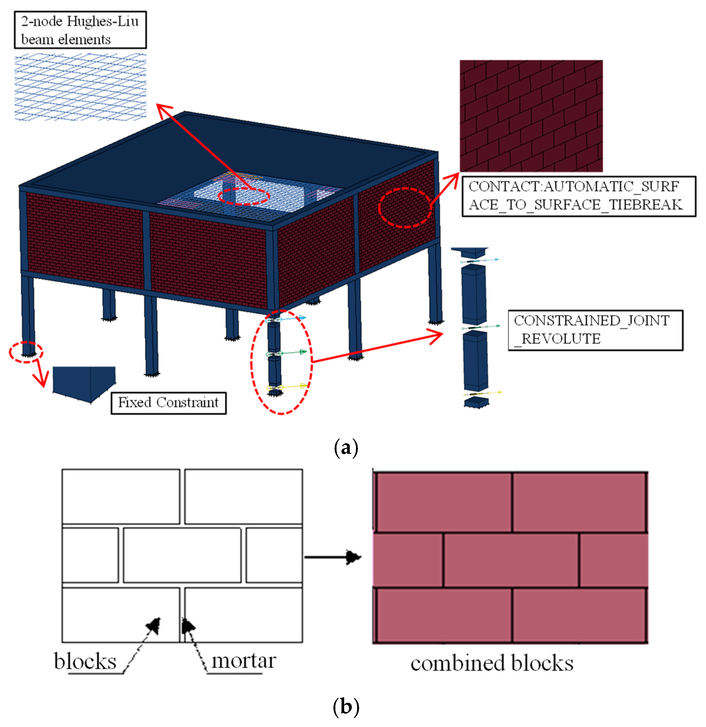
The modelling process commenced with the development of a refined finite element model for a pure RC frame, using ANSYS/LS-DYNA (R11.0). Subsequently, the infill wall RC frame was established by integrating masonry elements into the validated bare frame. As illustrated in Figure 2 and Figure 3, the developed refined finite element models for the pure and infilled RC frames are presented. The masonry infills were simulated by adopting the simplified micro-modelling approach put forward by Yu et al. [28]. As shown in Figure 3b, the mortar and blocks with the pre-existing thickness were simplified into a homogeneous material, and this homogeneous material was named “combined blocks”. The mortar is evenly wrapped around the block in the frame plane. The height of each composite block is the height of the block plus the width of the transverse mortar joint, and the width is the width of the block plus the width of the vertical mortar joint. Based on the sensitivity analysis of the grid size, the concrete grid was determined to be 100 mm and the reinforcement grid 50 mm, at which time the accuracy of the calculation results meets the requirements and does not significantly increase the computer’s storage resources and calculation time.

2.2.1. Selection of Elements and Materials

Concrete and infill wall blocks were modelled using an 8-node hexahedral solid element (Solid 164), and reinforcement was modelled using a 2-node Hughes–Liu beam element with a 2 × 2 Gaussian integral. The continuous surface cap model (*MAT_CSCM_CONCRETE) is utilized to simulate the nonlinear behaviour of concrete. This model automatically captures a series of critical nonlinear responses, including compressive hardening, post-peak softening, tensile cracking, confinement effects, and strain-rate effects. Earlier research by Yu et al. [28] has demonstrated that the original continuous surface cap model (*MAT_CSCM) can accurately replicate the damage patterns and resistance curves of infill walls. This model serves as the constitutive law for the homogenized ‘combined blocks’ material, capturing its key nonlinear responses. Additional trial computations indicate satisfactory consistency between the simulated and predicted time–displacement curves. Consequently, the simplified modelling approach, which employs this homogenized material model, is adopted in the present study to simulate the behavioural response of the infill wall. The reinforcement materials were characterized using the MAT_PLASTIC_KINEMATIC material model in LS-DYNA, which represents the steel’s stress–strain response with a bilinear elastic–plastic approximation. The embedded constraint method (*CONSTRAINED_BEAM_IN_SOLID) is implemented to simulate the composite action between reinforcing steel and concrete. The material model for the steel columns was defined as a linear elastic material *MAT_ELASTIC.

2.2.2. Load Arrangement and Column Removal Devices

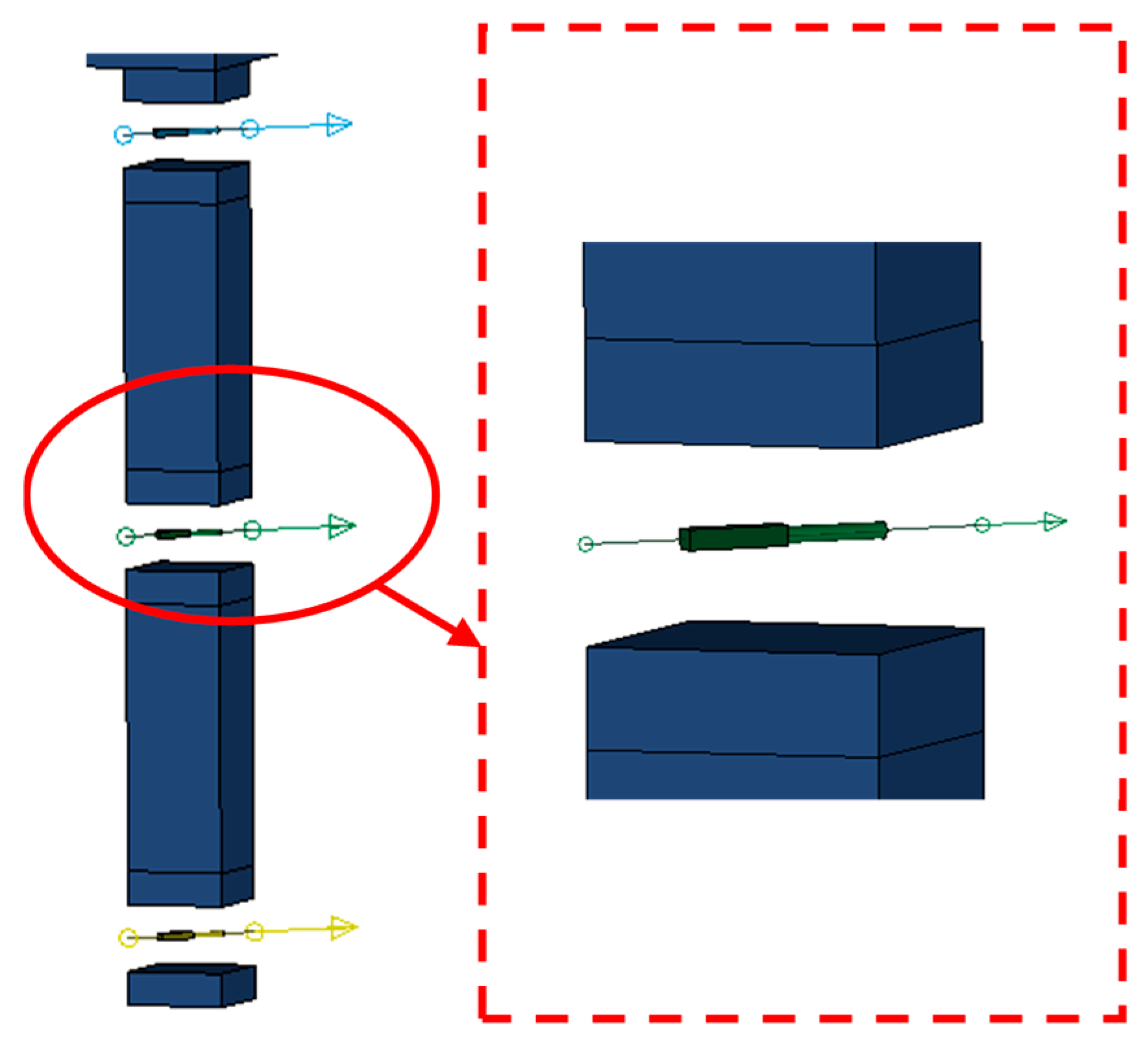
Gravity was applied globally to the model with LOAD_BODY_Y [29], whereas the live load was specifically imposed on the slab employing the *LOAD_SEGMENT keyword. As shown in Figure 4, for the column removal device in the finite element model, which consists of two sections of steel columns and three axle pins, the keyword *CONSTRAINED_JOINT_REVOLUTE is used to define the axle pins. To simulate the dynamic scenario of sudden column loss, the column removal is achieved by applying a forced displacement with a very short duration to the axle pins between the two steel columns, thereby instantaneously releasing the support. This approach allows the structure to vibrate freely under the action of gravity, capturing the inertial forces and dynamic amplification effects.

2.2.3. Masonry and Mortar Contact Mode

The masonry–mortar interface has a certain strength before failure [29], and after failure, the masonry and mortar joints can slide along the interface with each other. To accurately simulate the interaction between masonry and mortar, the keyword *CONTACT_AUTOMATIC_SURFACE_TO_SURFACE_TIEBREAK is used, that is, by defining the contact to reflect the crack development between the block and the block, between the block and the frame, and the sliding of the masonry. In the model, the failure of the masonry–mortar interface is characterized by a criterion based on its normal and shear strength properties (NFLS and SFLS). This criterion is formulated in Equation (1), where failure occurs when the combination of the acting normal stress σn and shear stress σs meets the defined threshold. The contact parameter tensile breaking strength of NFLS was determined to be 1.08 MPa, and shear breaking strength, SFLS, was determined to be 1.5 MPa, according to the research findings of Li et al. [26].
σ n 2 N F L S + σ S 2 S F L S 1

2.3. Validation of Finite Element Models

2.3.1. Comparison of Time–Displacement Curves

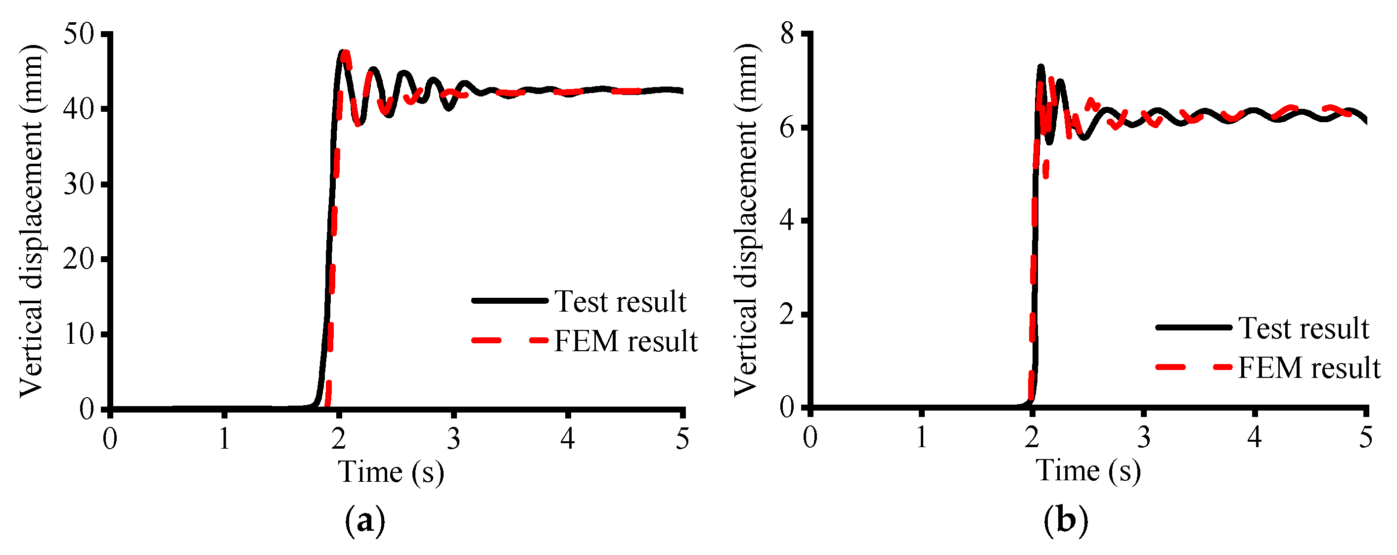
Figure 5a compares the numerical simulation results with the test results for the vertical displacement at the ground floor slab near the removed corner columns of the pure RC frame structure. The maximum displacement obtained from the simulation is 47.5 mm, which is 1.2% lower than the test results; the residual displacement obtained from the simulation is 42.4 mm, which is 0.9% lower than the test results, and it matches the trend of the time–displacement curves. These key parameters, namely the peak and residual vertical displacements, were directly extracted from the dynamic response history of the model. The close agreement demonstrates that the pure RC frame model can accurately simulate the dynamic response of the pure RC frame structure under sudden column removal.
Figure 5b compares the numerical simulation results of the vertical displacement at the ground floor slab near the removed corner column with the test results. In the test, the maximum value of displacement near the ground floor corner column is 7.8 mm, and the residual value is 6.3 mm. The simulation result of the maximum value of displacement near the corner column is 5% lower than the test result, and the simulation result of the residual value of displacement is 1.6% higher than the test result. Similarly, these displacement parameters were measured using the simulation output. The numerical simulation results are close to the experimental results, and the trend of time–displacement curves is in good agreement, so it can be seen that the infill wall RC frame model can also effectively predict the dynamic response.

2.3.2. Comparison of Damage Modes

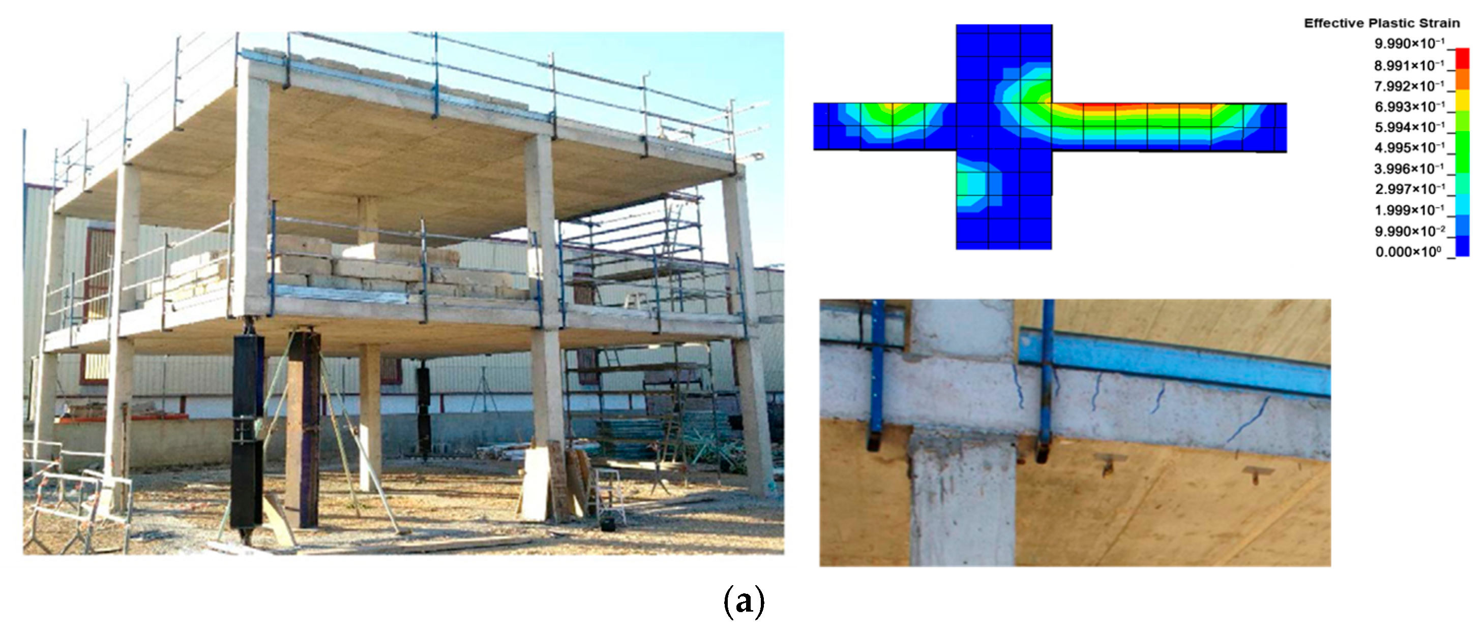
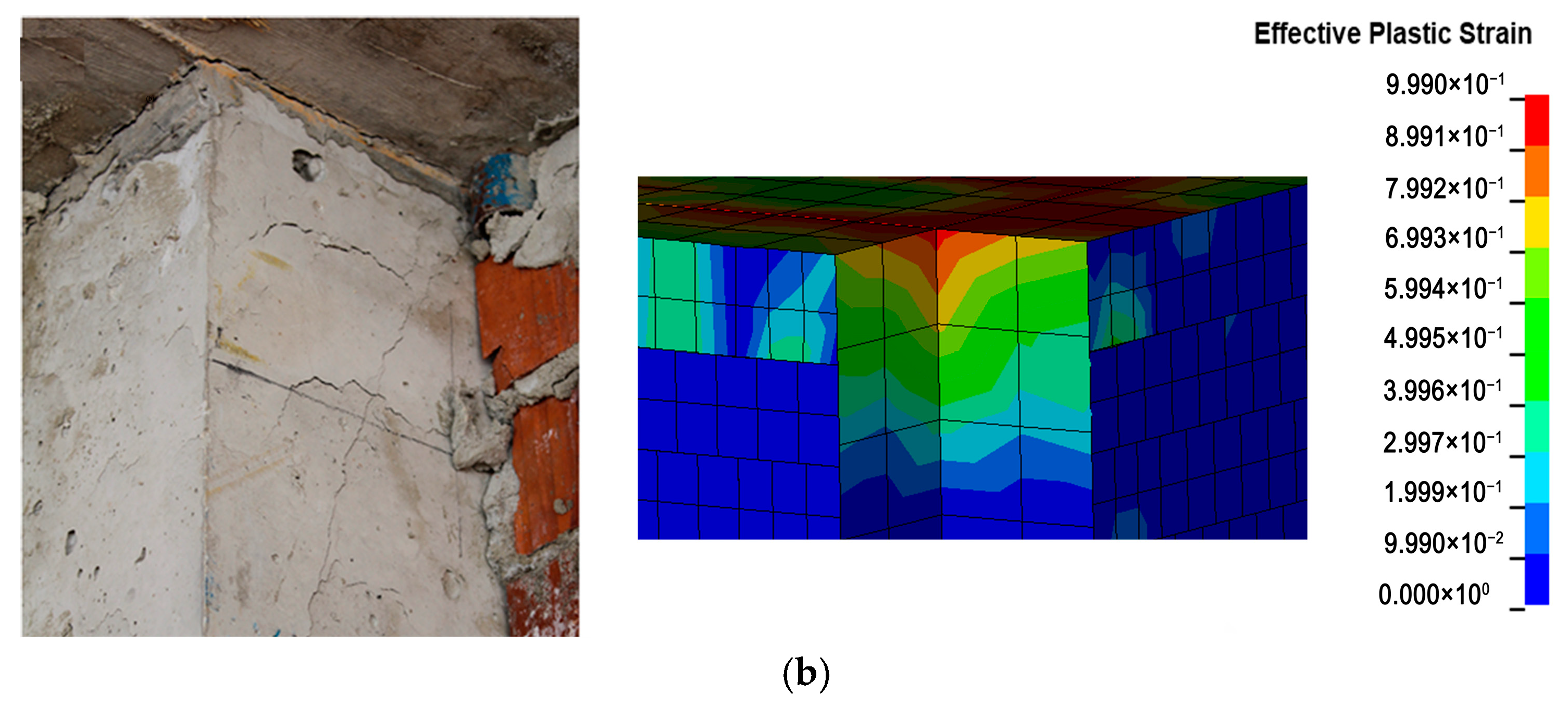
Figure 6 shows the damage modes of the pure RC frame structure and the damage modes of the finite element model. The experimental damage in the pure RC frame was primarily characterized by bending cracks at the slab–column nodes, with no extensive cracking observed elsewhere. As evidenced by Figure 6a, the finite element model successfully captured this failure mode. For the infill wall frame, the significant increase in initial stiffness provided by the masonry prevented visible cracking immediately after the column removal. However, subsequent static loading induced tensile cracks at the connection between the corner column and the second-story slab. The close agreement between these experimental observations and the numerical damage patterns in Figure 6b validates the model’s accuracy in simulating the damage mechanisms for both structural configurations.

3. Influence of Column Removal Devices

The real situation where the structure is subjected to incidental loads, such as explosion and impact, will result in the instantaneous removal of columns. This study aims to investigate the performance of the structure in the case of complete failure of corner columns, in order to provide more conservative research data for the structural design. The incomplete removal of the corner columns in the two tests still has an effect on the remaining structure, and the column removal device will co-vibrate with the structure, thus affecting the dynamic response of the structure to collapse.
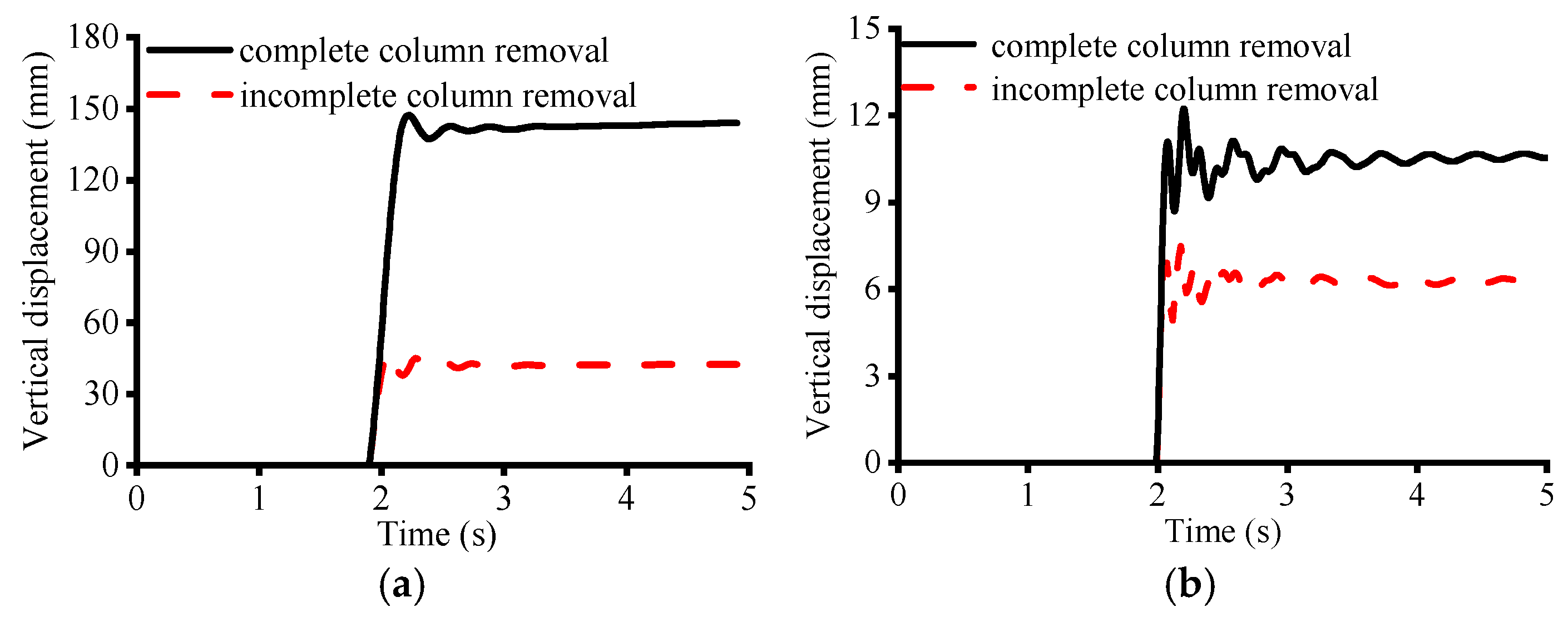
In order to investigate the effect of the column removal device on the results, two types of column removal models were established. One is defined as an incomplete column removal device, as shown in Figure 4; the other is defined as a complete column removal device by completely removing the corner columns using the keyword * MAT_ADD_EROSION. Figure 7 shows the time–displacement curves of the pure RC frame structure, and the infill wall RC frame structure with different column removal devices, respectively.
The analysis of the pure RC frame revealed a profound influence of the column removal method. Under the incomplete removal scenario, the structure exhibited a peak displacement of 47.5 mm and a residual displacement of 42.5 mm. In contrast, simulating complete column loss resulted in drastically larger displacements, with peaks reaching 147.4 mm and residual values of 141.4 mm. Structural stiffness, defined as the force per unit displacement, was calculated to be 3.2 × 10³ kN/m for the incomplete removal model, which plummeted to 1.0 × 10³ kN/m for the complete removal condition. The amplitude of the structure decreases, the period increases, and the damping ratio decreases during vibration, but the peak displacement of the model with a complete column removal device increases by 210.3%, the residual displacement increases by 238.1%, the vibration period increases by 41.7%, and the stiffness decreases by 68.8%, compared with that of the model with an incomplete column removal device. The analysis indicates that the incomplete column removal device notably augments the structural stiffness and damping ratio. This contributes to a longer vibration period, which in turn results in mitigated peak and residual displacements and a more rapid stabilization of the structural response.
For the infill wall RC frame structure, the peak displacement of the structure is 7.5 mm, the residual displacement is 6.3 mm, and the stiffness is 3.9 × 10⁴ kN/m for the incomplete column removal, and the peak displacement is 12.3 mm, the residual displacement is 10.6 mm, and the stiffness is 2.4 × 10⁴ kN/m for the complete column removal, and the amplitude of the structure decreases throughout the vibration process, the vibration period increases, and the damping ratio decreases, but the model of the complete column removal device is better than the incomplete column removal device, and the structure stabilizes faster. The model with the column removal device is 64.4% larger than the model with incomplete column removal in terms of peak displacement, 68.8% larger in terms of residual displacement, 18.2% larger in terms of vibration period, and 38.5% smaller in terms of stiffness. Due to the increase in the period of decrease in structural stiffness, it can be seen that the incomplete column removal device also increases the stiffness to damping ratio of the structure, which results in an increase in the period of vibration of the structure, and a decrease in the peak and residual displacements of the structure, which stabilizes more quickly.
In summary, by comparing the peak and residual displacements with different column removal devices, it can be seen that the effect of the column removal device on the structure is not negligible, and it has a greater effect on the stiffness of the pure RC frame structure. In reality, since the structure is subjected to accidental loads more often in the fully de-columnized condition, the results obtained by using incomplete column removal devices are often biased towards insecurity, so the complete column removal devices will be used in the next study and analysis.

4. Effect of Infill Wall Openings on Collapse Resistance of RC Space Frame Structures

The presence of masonry infill walls can significantly increase the overall structural stiffness and thus effectively reduce the risk of structural collapse. However, the door and window openings that may be provided in an infill wall can alter its stiffness accordingly, which in turn can weaken its contribution to the structural resistance to varying degrees, ultimately affecting the infill wall’s ability to resist progressive collapse. The research in this section aims to investigate the influence of the laws of these changes on the progressive collapse resistance of RC space frame structures by changing the locations of door openings, as well as the size and number of window openings, in depth.

4.1. Effect of Doorway Location on Resistance to Progressive Collapse

In order to investigate the effect of doorway position on the resistance of RC frame structure with an open infill wall to resist progressive collapse, a finite element model was designed, as shown in Figure 8, with the labelling D-L, where D denotes the open doorway, and L represents the distance from the centre of the doorway to the failure column.
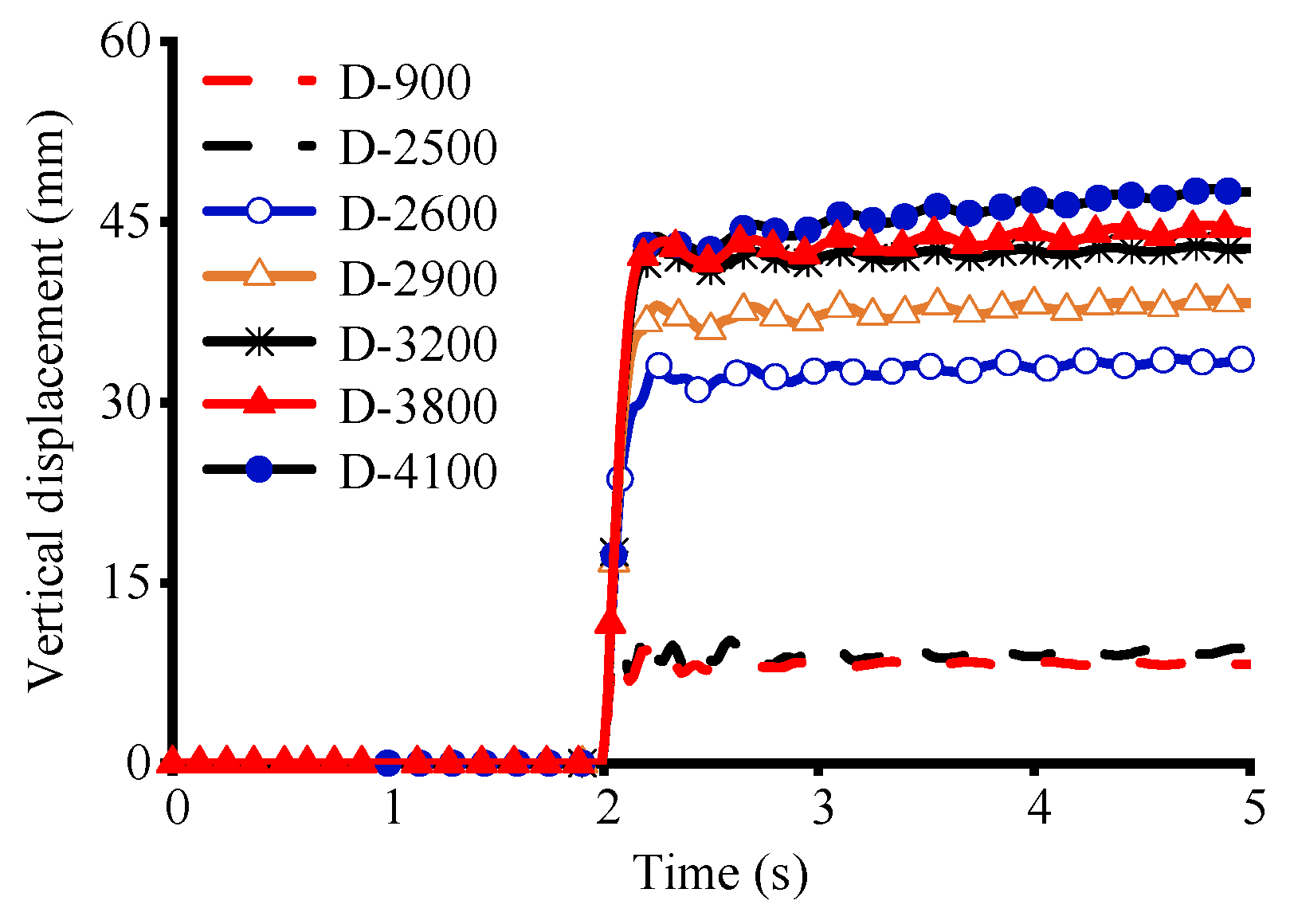
The time–displacement curves near the structural corner columns at different doorway locations are shown in Figure 9. With the increase in the value of L, the displacement near the structural corner column increases gradually. The displacement near the structural corner column increases by 19% when the door that is opening is 2500 mm away from the failure column compared with 900 mm away from the failure column, the structural vibration period increases by 0.9%, and the stiffness decreases by 18.1%; the displacement near the structural corner column increases by 296% when the distance is increased to 2600 mm, the structural vibration period increases by 9.3%, and the stiffness decreases by 71.5%; when the distance is increased to 3800 mm, the structural vibration period decreases by 9.3%, and the stiffness decreases by 71.5%; when the distance is increased to 3800 mm, the displacement near the structural corner column increases by 360%, the structural vibration period increases by 10.6%, and the stiffness decreases by 78.2%; and when the distance is increased to 4100 mm, the displacement near the structural corner column reaches the maximum value and increases gradually with the increase in time, and the time–displacement curve begins to not converge.
Figure 10 shows the curve of structural displacement versus the position of the open doorway, taking the distance from the centre of the doorway to the failure column as the horizontal coordinate, and taking the maximum displacement of the structure after removing the column as the vertical coordinate. It can be seen that the displacement near the corner columns of the structure increases with the increase in distance, and the rate of change in the displacement value near the corner columns of the structure is larger when 2500 < L < 2600.
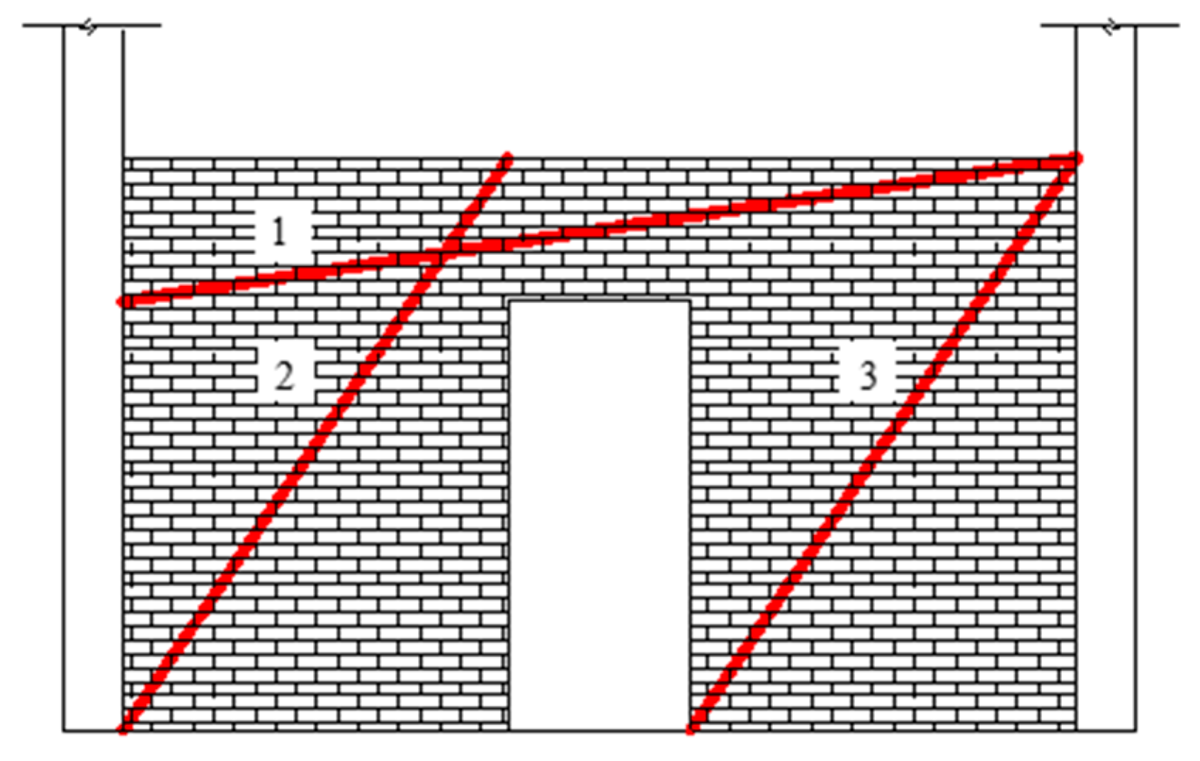
As shown in Figure 11, the infill wall can be equated to three struts to transfer the load when opening a doorway [30], and the width of the wall affects the effective area of the strut, which in turn affects the stiffness of the strut. Strut 1 is the same for different doorway locations, and strut 2 and strut 3 vary with the doorway location. The specimen after the failure of the corner column is equated to a cantilever member, subjected to uniform load, and the area near its fixed end (strut 2), is subjected to a larger bending moment and shear force, which plays a controlling role in the structural load-carrying capacity. The larger the distance between the doorway centre and the failed column, the smaller the effective area of strut 2, and the more the structural capacity is weakened, while strut 3 is located in the cantilever end and needs to withstand a much smaller applied load than strut 2, thereby having a limited enhancing effect on the structural load-carrying capacity, due to the increase in the effective area of strut 3, so the weakening of the effective area of strut 2 or the increase in the structural stiffness of the structure of the impact is more significant.
When L < 2500 mm, the effective area of strut 2 is large. The bearing capacity of the structure is sufficient to resist the load, and the influence of the change in the doorway location on area 2 is small. As a result, the rate of change in the displacement near the structural corner columns is very small. When 2500 < L < 2600 mm, the reduction in the effective area of strut 2 accelerates the rate of reduction in the structural load-bearing capacity, causing the rate of change in the displacement near the structural corner columns to increase abruptly. When L > 2600 mm, the effective area of strut 2 has been greatly reduced, and its contribution to the structural load-carrying capacity is also significantly decreased. At this time, continuing to reduce the effective area of strut 2 has a weaker influence on the structural load-carrying capacity. Therefore, the rate of change in the displacement near the structural corner column slows down.

4.2. Effect of Opening Rate and Number of Openings on Resistance to Progressive Collapse

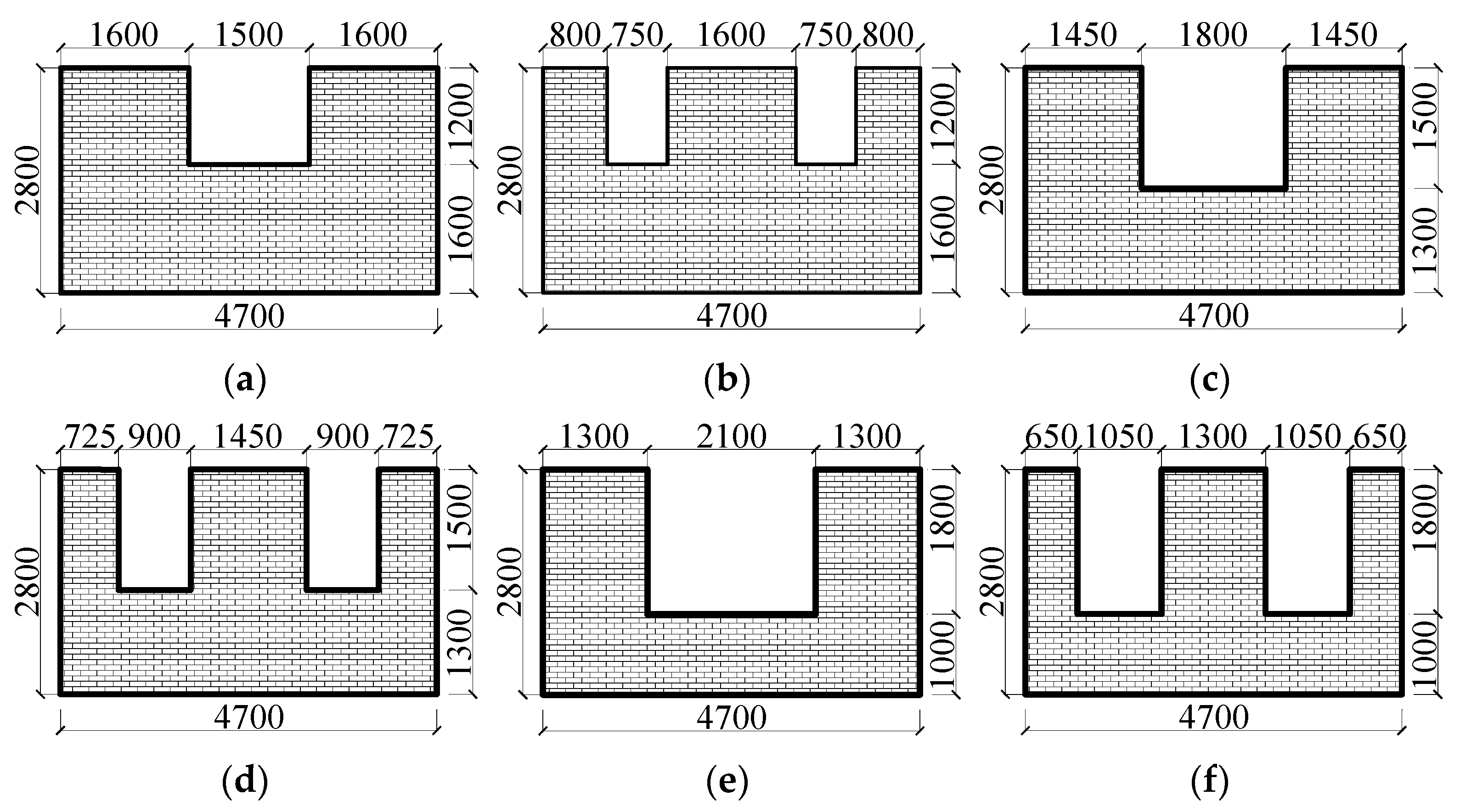
This section investigates the effect of opening size on the progressive collapse performance of the RC space frame. The analysis employs an infill wall model (Figure 12) derived from the validated prototype. In this model, the nomenclature W-P%-N is adopted, with W signifying a window opening, P the opening rate (opening area/wall area), and N the quantity of openings.
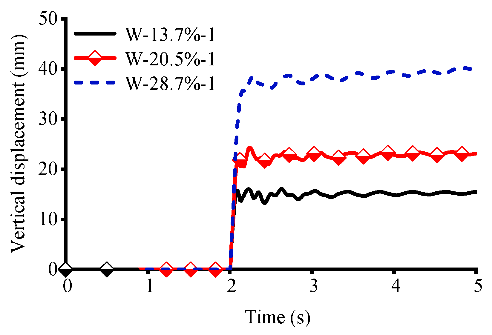
The time-displacement curves near the structural corner columns for different opening rates at one window opening are shown in Figure 13. When the opening rate increases from 13.7% to 20.5% with one window opening, the structural displacement increases by 51.5%, the vibration period increases by 15.4%, and the structural stiffness decreases by 34.0%. When the opening rate continues to increase to 28.7%, the structural displacement increases by 139.6%, the structural vibration period increases by 75%, and the structural stiffness decreases by 58.3%.
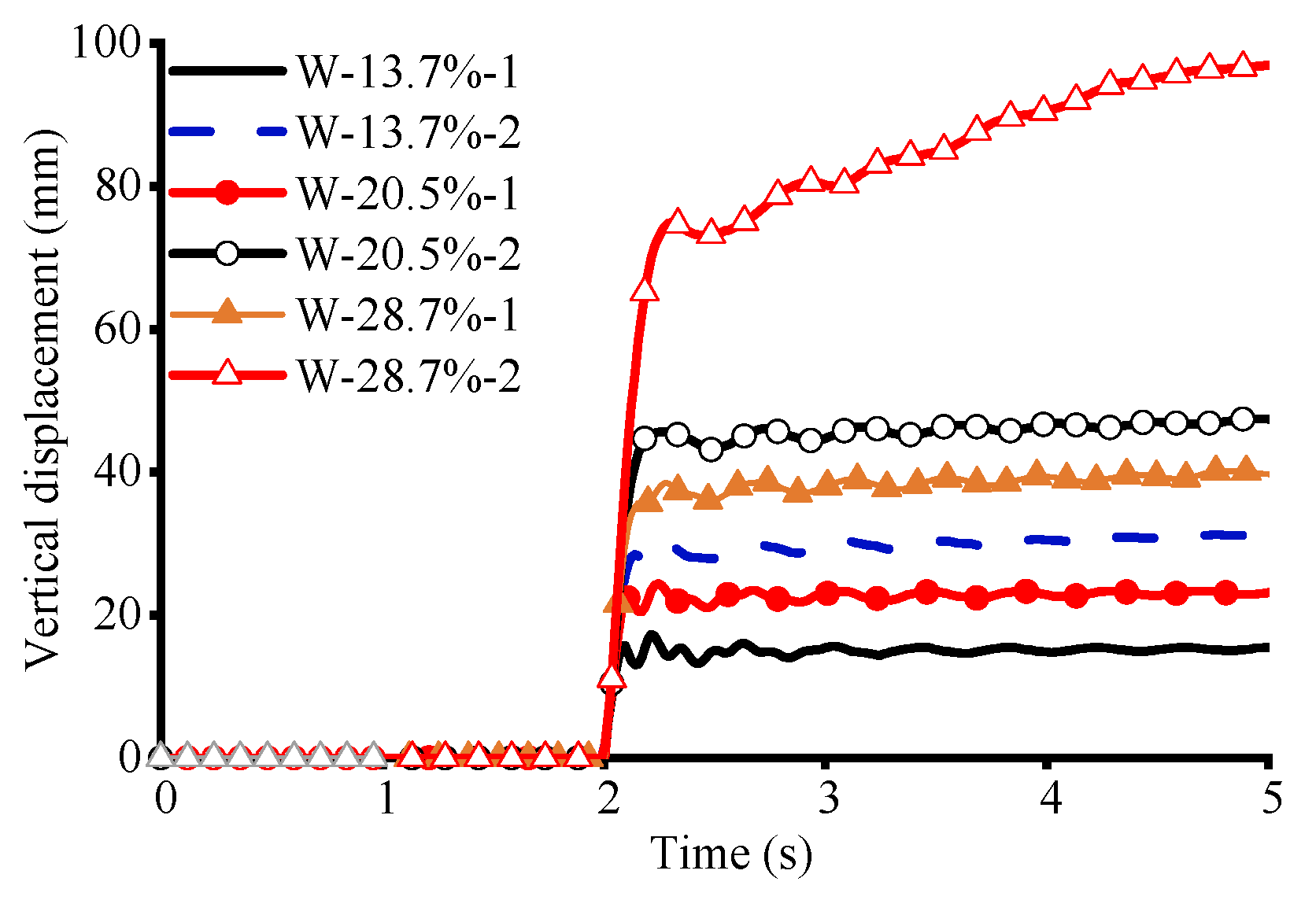
Figure 14 shows the time-displacement curves near the structural corner columns for different numbers of window openings under the three opening rates. As can be seen in Figure 15, when the opening rate is 13.7%, compared with one window opening, two window openings increase the structural displacement and vibration period by 73.3% and 0.7%, respectively, and decrease the structural stiffness by 43.3%. When the opening rate is 20.5%, two window openings increase the structural displacement and vibration period of one window opening by 149.6% and 11.4%, respectively, and decrease the stiffness by 46.7%. When the opening rate is 28.7%, compared with one window opening, two window openings increase the structural displacement and vibration period by 75% and 42.9%, respectively, and decrease the stiffness by 58.3% and 48.7%. The weakening of the structural stiffness, due to the increase in the number of openings, is more significant when the opening rate is larger, and the increase in the number of openings has a more significant impact on the structural stiffness than the increase in the opening rate.
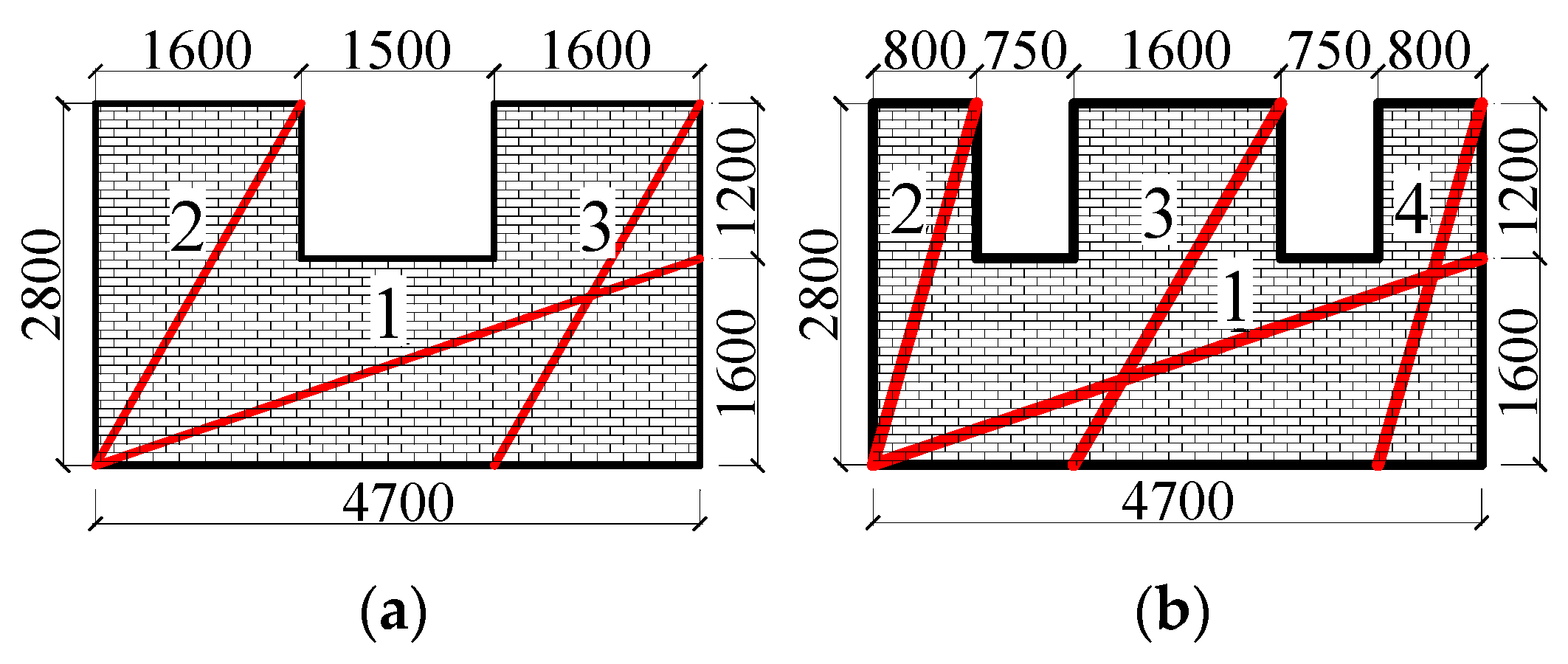
Figure 15 shows that, for example, when the opening rate is 13.7% in the structure, the infill wall can be equated to three and four compression rods to transfer the load when one and two windows are opened [30], and the width of the wall affects the effective area of the compression rods, which in turn affects the stiffness of the compression rods. For the same opening rate but different numbers of window openings, strut 1 remains the same, and the number of openings affects the strength of the remaining struts. The specimen after the failure of the corner column is equivalent to a cantilever member subjected to a uniform load, and the area near its fixed end (strut 2) is subjected to a larger bending moment and shear force, which plays a controlling role in the structural load-carrying capacity. When two window openings are opened, the effective area of strut 2 is reduced, and the structural load-carrying capacity is weakened, while the other struts located at the cantilever end need to withstand a much lower imposed load than strut 2, and thus strut 3 and strut 4 have a limited contribution to the structural load-carrying capacity; thus, the weakening or increasing of the effective area of strut 2 has a more sensitive effect on the structural stiffness. Since increasing the number of openings is stronger than increasing the rate of the openings for the weakening of the effective area of strut 2, the increase in the number of openings has a more significant effect on the structural stiffness than the increase in the rate of the openings.

5. Conclusions

This study elucidates the following key findings regarding the influence of infill walls on progressive collapse resistance, with particular emphasis on two original aspects: the effect of column removal methods and the behaviour of walls with openings.
  • A comparative analysis of refined finite element models with complete and incomplete column removal demonstrates that the simulation method exerts a non-negligible influence on the structural response. This effect is particularly pronounced for the pure RC frame, where the incomplete removal method significantly overestimates structural stiffness, leading to non-conservative and potentially unsafe predictions;
  • After the removal of corner columns in the infill wall with openings, diagonal struts will be formed in the corresponding area to transfer the load. The strength of the struts near the fixed end has the most significant effect on the structural stiffness and plays a controlling role. With the increase in the distance from the doorway to the failure column, the increase in the opening rate, and the increase in the number of openings, the effective area of the struts near the fixed end decreases, the strength of the struts decreases, and the structural stiffness is weakened. The value of the structural stiffness decreases by up to 78.2%;
  • The closer the door-opening position is to the fixed end, the more significantly the structural stiffness is weakened. When the position of the doorway moves from the centre of the wall length to the fixed end (2500 mm < L < 2600 mm), the structural stiffness decreases the most significantly. When it continues to move further towards the fixed end, the rate of decrease in structural stiffness slows down;
  • The analysis reveals that for opening ratios below 8%, structural stiffness is more sensitive to the number of discrete openings than to the overall opening ratio, highlighting the importance of opening dispersion.

6. Future Work

This study primarily focuses on corner column failure scenarios. However, internal or edge column failures are more prevalent in actual blast or impact events, which may trigger distinct internal force redistribution paths and collapse mechanisms (with significantly different contributions from catenary action, the beam mechanism, and compressive arch action). Furthermore, although the “complete removal” assumption is conservative, it fails to accurately simulate complex dynamic processes, such as debris impact and coupled wave-loading effects, that are generated by real explosions. Accordingly, future research should prioritize dynamic testing of infill walls with openings to validate numerical models, and extend investigations to more complex scenarios, including edge and internal column failures, composite slab interactions, and multi-hazard coupling effects.

Author Contributions

Conceptualization, J.-L.W. and Z.L.; methodology, Z.L.; software, H.L.; validation H.L. and Y.Z.; writing—original draft preparation, Y.Z.; writing—review and editing, T.-Q.X.; visualization, H.L. and Y.W.; supervision, T.-Q.X.; project administration, J.-L.W.; funding acquisition, Z.L. All authors have read and agreed to the published version of the manuscript.

Funding

This research is supported by the Guangxi Natural Science Foundation (Nos. AD25069101 and 2025GXNSFAA069803), and the National Natural Science Foundation of China (No. 52308489).

Data Availability Statement

The data presented in this study are available on request from the corresponding author.

Conflicts of Interest

The authors declare no conflict of interest.

References

  1. Zucca, M.; Tattoni, S.; Di Castri, M.; Simoncelli, M. On the collapse of a post-tensioned reinforced concrete truss bridge during the construction phases. Eng. Fail. Anal. 2024, 158, 107999. [Google Scholar] [CrossRef]
  2. Abdelwahed, B. A review on building progressive collapse, survey and discussion. Case Stud. Constr. Mater. 2019, 11, e00264. [Google Scholar] [CrossRef]
  3. Russell, J.M.; Sagaseta, J.; Cormie, D.; Jones, A.E.K. Historical review of prescriptive design rules for robustness after the collapse of Ronan Point. Structures 2019, 20, 365–373. [Google Scholar] [CrossRef]
  4. Marjanishvili, S.M. Progressive analysis procedure for progressive collapse. J. Perform. Constr. Facil. 2004, 18, 79–85. [Google Scholar] [CrossRef]
  5. Yu, J.; Tan, K.H. Analytical model for the capacity of compressive arch action of reinforced concrete sub-assemblages. Mag. Concr. Res. 2014, 66, 109–126. [Google Scholar] [CrossRef]
  6. Kang, S.B.; Tan, K.H. Analytical Model for Compressive Arch Action in Horizontally Restrained Beam-Column Subassemblages. ACI Struct. J. 2016, 113, 813–826. [Google Scholar] [CrossRef]
  7. Yi, F.; Yi, W.J.; Sun, J.M.; Zhou, Y.; Zhang, W.X.; He, Q.F. Experimental study on progressive collapse behavior of frame structures triggered by impact column removal. Eng. Struct. 2024, 321, 119022. [Google Scholar] [CrossRef]
  8. Qian, K.; Geng, S.Y.; Liang, S.L.; Fu, F.; Yu, J. Effects of loading regimes on the structural behavior of RC beam-column sub-assemblages against disproportionate collapse. Eng. Struct. 2022, 25, 1113470. [Google Scholar] [CrossRef]
  9. Sasani, M.; Sagiroglu, S. Gravity load redistribution and progressive collapse resistance of 20-story reinforced concrete structure following loss of interior column. ACI Struct. J. 2010, 107, 636–644. [Google Scholar] [CrossRef]
  10. Sasani, M.; Kazemi, A.; Sagiroglu, S.; Forest, S. Progressive Collapse Resistance of an Actual 11-Story Structure Subjected to Severe Initial Damage. J. Struct. Eng. 2011, 137, 893–902. [Google Scholar] [CrossRef]
  11. Qian, K.; Li, B. Dynamic performance of RC beam-column substructures under the scenario of the loss of a corner column—Experimental results. Eng. Struct. 2012, 42, 154–167. [Google Scholar] [CrossRef]
  12. Yu, J.; Luo, L.Z.; Fang, Q. Structure behavior of reinforced concrete beam-slab assemblies subjected to perimeter middle column removal scenario. Eng. Struct. 2020, 208, 110336. [Google Scholar] [CrossRef]
  13. Ma, F.; Gilbert, B.P.; Guan, H.; Xue, H.; Lu, X.; Li, Y. Experimental study on the progressive collapse behaviour of RC flat plate substructures subjected to corner column removal scenarios. Eng. Struct. 2019, 180, 728–741. [Google Scholar] [CrossRef]
  14. Adam, J.M.; Buitrago, M.; Bertolesi, E.; Sagaseta, J.; Moragues, J.J. Dynamic performance of a real-scale reinforced concrete building test under a corner-column failure scenario. Eng. Struct. 2020, 210, 110414. [Google Scholar] [CrossRef]
  15. Sasani, M.; Werner, A.; Kazemi, A. Bar fracture modeling in progressive collapse analysis of reinforced concrete structures. Eng. Struct. 2011, 33, 401–409. [Google Scholar] [CrossRef]
  16. Pham, A.T.; Lim, N.S.; Tan, K.H. Investigations of tensile membrane action in beam-slab systems under progressive collapse subject to different loading configurations and boundary conditions. Eng. Struct. 2017, 150, 520–536. [Google Scholar] [CrossRef]
  17. Qian, K.; Cheng, J.F.; Weng, Y.H.; Fu, F. Effect of loading methods on progressive collapse behavior of RC beam-slab substructures under corner column removal scenario. J. Build. Eng. 2021, 44, 103258. [Google Scholar] [CrossRef]
  18. Tsai, M.H.; Huang, T.C. Progressive collapse analysis of an RC building with exterior partially infilled walls. Struct. Des. Tall Spec. Build. 2011, 22, 327–348. [Google Scholar] [CrossRef]
  19. Kong, J.; Zhai, C.; Wang, X. In-plane behavior of masonry infill wall considering out-of-plane loading. Period. Polytech.- Civ. Eng. 2016, 60, 217–221. [Google Scholar] [CrossRef]
  20. Qian, K.; Lan, D.Q.; Fu, F.; Li, B. Effects of infilled wall opening on load resisting capacity of RC frames to mitigate progressive collapse risk. Eng. Struct. 2020, 223, 111196. [Google Scholar] [CrossRef]
  21. Qian, K.; Li, B. Effects of Masonry Infill Wall on the Performance of RC Frames to Resist Progressive Collapse. J. Struct. Eng. 2017, 143, 04017118. [Google Scholar] [CrossRef]
  22. Brodsky, A.; Yankelevsky, D.Z. Resistance of reinforced concrete frames with masonry infill walls to in-plane gravity loading due to loss of a supporting column. Eng. Struct. 2017, 140, 134–150. [Google Scholar] [CrossRef]
  23. Stinger, S.M.; Orton, S.L. Experimental Evaluation of Disproportionate Collapse Resistance in Reinforced Concrete Frames. ACI Struct. J. 2013, 110, 521–529. [Google Scholar]
  24. Shan, S.D.; Li, S.; Xu, S.Y.; Xie, L.L. Experimental study on the progressive collapse performance of RC frames with infill walls. Eng. Struct. 2016, 111, 80–92. [Google Scholar] [CrossRef]
  25. Baghi, H.; Oliveira, A.; Valençac, J.; Cavaco, E.; Neves, L.; Júlio, E. Behavior of reinforced concrete frame with masonry infill wall subjected to vertical load. Eng. Struct. 2018, 171, 476–487. [Google Scholar] [CrossRef]
  26. Li, S.; Shan, S.; Zhai, C.; Xie, L. Experimental and numerical study on progressive collapse process of RC frames with full-height infill walls. Eng. Fail. Anal. 2016, 59, 57–68. [Google Scholar] [CrossRef]
  27. Buitrago, M.; Bertolesi, E.; Sagaseta, J.; Calderón, P.A.; Adam, J.M. Robustness of RC building structures with infill masonry walls: Tests on a purpose-built structure. Eng. Struct. 2021, 226, 111384. [Google Scholar] [CrossRef]
  28. Yu, J.; Gan, Y.P.; Wu, J.; Wu, H. Effect of concrete masonry infill walls on progressive collapse performance of reinforced concrete infilled frames. Eng. Struct. 2019, 191, 179–193. [Google Scholar] [CrossRef]
  29. Qian, K.; Wang, D.F.; Huang, T.; Weng, Y.H. Initial damage and residual behavior of RC beam-slab structures following sudden column removal—Numerical study. Structures 2022, 36, 650–664. [Google Scholar] [CrossRef]
  30. Shan, S.; Li, S.; Wang, S. Effect of infill walls on mechanisms of steel frames against progressive collapse. J. Constr. Steel Res. 2019, 162, 105720. [Google Scholar] [CrossRef]
Figure 1. Pure RC frame and infill wall RC frame structural entities: (a) pure frame structural entities; (b) infill wall frame structural entities.
Buildings 15 03778 g001
Figure 2. Finite element modelling of pure RC frame.
Buildings 15 03778 g002
Figure 3. Finite element modelling of infill wall RC frames: (a) model of reinforced concrete; (b) simplified details of microscopic modelling.
Buildings 15 03778 g003
Figure 4. Finite element column removal device.
Buildings 15 03778 g004
Figure 5. Time–displacement curves: (a) pure frame; (b) infill wall frames.
Buildings 15 03778 g005
Figure 6. The failure modes of pure RC frame structure and infill wall RC frame structure under experiment and finite element: (a) pure RC frame; (b) infill wall RC frame.
Buildings 15 03778 g006aBuildings 15 03778 g006b
Figure 7. Time–displacement curves:(a) pure RC frames; (b) infill wall RC frames.
Buildings 15 03778 g007
Figure 8. Finite element modelling of open doorways.
Buildings 15 03778 g008
Figure 9. Effect of the location of the door opening on the time–displacement curve.
Buildings 15 03778 g009
Figure 10. Distance–displacement curve of door opening.
Buildings 15 03778 g010
Figure 11. Load transfer route when opening the door.
Buildings 15 03778 g011
Figure 12. Finite element model of infill wall openings: (a) W-13.7%-1; (b) W-13.7%-2; (c) W-20.5%-1; (d) W-20.5%-2; (e) W-28.7%-1; and (f) W-28.7%-2.
Buildings 15 03778 g012
Figure 13. Effect of opening rate on time-displacement curves.
Buildings 15 03778 g013
Figure 14. Effect of numbers of window openings on time-displacement curves.
Buildings 15 03778 g014
Figure 15. Load transfer route when opening the window: (a) W-13.7%-1; (b) W-13.7%-2.
Buildings 15 03778 g015
Disclaimer/Publisher’s Note: The statements, opinions and data contained in all publications are solely those of the individual author(s) and contributor(s) and not of MDPI and/or the editor(s). MDPI and/or the editor(s) disclaim responsibility for any injury to people or property resulting from any ideas, methods, instructions or products referred to in the content.