Article

Study on Mooring Design and Hydrodynamic Performance of Floating Offshore Wind Turbines with CFRP Mooring Lines

1
School of Architecture and Civil Engineering, Jiangsu University of Science and Technology, Zhenjiang 212100, China
2
College of Naval Architecture and Ocean Engineering, Jiangsu University of Science and Technology, Zhenjiang 212100, China
3
School of Civil Engineering, Hohai University, Nanjing 210024, China
4
National and Local Unified Engineering Research Center for Basalt Fiber Production and Application Technology, Southeast University, Nanjing 210096, China
5
School of Civil Engineering, Shandong Jianzhu University, Jinan 250101, China
*
Authors to whom correspondence should be addressed.
Buildings 2025, 15(20), 3734; https://doi.org/10.3390/buildings15203734
Submission received: 3 September 2025 / Revised: 7 October 2025 / Accepted: 14 October 2025 / Published: 16 October 2025

Abstract

To address the issues of traditional mooring lines, such as high self-weight, low strength, and poor durability, Carbon-Fiber-Reinforced Polymer (CFRP) was investigated as a material for mooring lines of offshore floating wind turbines, aiming to achieve high performance, lightweight design, and long service life for mooring systems. Based on a “chain–cable–chain” configuration, a CFRP mooring line design is proposed in this study. Taking a 5 MW offshore floating wind turbine as the research object, the dynamic performance of offshore floating wind turbines with steel chains, steel cables, polyester ropes, and CFRP mooring lines under combined wind, wave, and current loads was compared and analyzed to demonstrate the feasibility of applying CFRP mooring lines by combining the potential flow theory and the rigid–flexible coupling multi-body model. The research results indicate that, compared to traditional mooring systems such as steel chains, steel cables, and polyester ropes, (1) under static water, the CFRP mooring system exhibits a larger static water free decay response and longer free decay duration; (2) under operating sea conditions, the motion response and mooring tension of the offshore floating wind turbine with CFRP mooring lines are smaller than those with steel cables and steel chains but greater than those with polyester ropes; and (3) under extreme sea conditions, the motion responses of the offshore floating wind turbine with CFRP mooring lines are smaller than those with steel wire ropes and steel chains but close to the displacement responses of the polyester rope system, while the increase in mooring tension is relatively moderate and the safety factor is the highest.

1. Introduction

With the saturation of nearshore wind resources, there is a growing and evident trend in the expansion of offshore wind power into deep-sea territories. Floating offshore wind turbines, characterized by their large capacity, high power generation efficiency, strong environmental adaptability, minimal ecological impact, and low construction costs, have become the key to developing deep-sea wind resources. As the critical component of floating offshore wind turbines, the mooring line can prevent displacement or drifting due to wave and current actions, which could ensure the safety of both the turbines and maritime traffic. Existing mooring lines are primarily made of chains, steel cables, and synthetic fiber ropes (such as polyester and polyethylene). With the increase in water depth and sea conditions becoming more severe, the disadvantages of traditional mooring systems, including high self-weight, low fatigue strength, poor long-term durability, and high installation and maintenance costs, have become a bottleneck hindering the advancement of floating wind turbines into deep waters. Replacing these traditional mooring lines with CFRP cables can meet the demands for lightweight, long-life, and high-performance mooring systems in floating offshore wind turbines owing to their exceptional properties such as light weight, high strength, superior fatigue resistance, and excellent corrosion durability. Compared to traditional mooring systems such as anchor chains, steel cables, and polyester ropes, CFRP mooring lines offer high-strength and lightweight characteristics, resulting in lower requirements for installation vessels and floating structures. Consequently, transportation and installation costs can be effectively reduced. In addition, the excellent corrosion resistance of CFRP mooring lines minimizes the need for frequent inspections and anti-corrosion maintenance, leading to a significant reduction in life-cycle operation and maintenance costs. With the continuous expansion of carbon fiber production capacity and ongoing optimization of cable manufacturing processes, the foundation for large-scale production of CFRP mooring lines has become increasingly well-established. Relevant enterprises already possess numerous mature production lines, providing the necessary basis for large-scale conversion and production. In conclusion, the application of CFRP mooring line provides an effective approach to overcome the performance limitations of mooring technology and promotes the development of offshore wind power towards deep-sea areas.
Due to the early dominance of fixed-bottom wind turbines in the offshore wind industry and the long-standing high cost of carbon fiber, there were relatively few related studies on the application of CFRP mooring lines. Based on pultruded helical CFRP rods, D. Jackson et al. [1] proposed a CFRP mooring cable design for floating offshore drilling platforms after comparing the physical and mechanical properties of steel wire ropes, polyester ropes, HMPE ropes, and CFRP tendons. By a numerical simulation method, Eduardo [2] analyzed the mechanical behavior of stranded and helical CFRP mooring lines under tensile and bending loads. The results indicated that helical CFRP mooring cables exhibited higher breaking loads and greater minimum bending radius. Currently, CFRP materials are also being utilized in other marine structures due to the excellent physical and chemical performance of carbon fiber. For instance, Menezes et al. [3] investigated a 1000 m tension-leg production riser using a composite structure comprising ±20° carbon fiber laminate layers and circumferential glass fiber reinforcement. To verify the feasibility of CFRP composite production risers, the axial tension–pressure failure load envelope of the overall structure was analyzed. Amaechi et al. [4] conducted stress analysis on a deep-water CFRP riser using finite element analysis software (ANSYS ACP 19.0), examining the safety factors of the overall structure under various loading conditions and performing certain optimizations on key parameters. Zhang et al. [5,6] considered failure mechanisms such as tensile failure and torsional failure of umbilical cables and analyzed their reliability. The application of carbon fiber composite materials in marine pipes and cables can not only meet lightweight requirements but also enhance structural strength.
In contrast to the limited research on CFRP mooring lines, existing studies on CFRP cables primarily focused on terrestrial structures such as cable-stayed bridges, suspension bridges, tied-arch bridges, and prestressed spatial cable structures. Studies on CFRP cables for cable-stayed bridges began in 1987 with Meier’s proposal to use CFRP cables for the envisioned 8400 m span Gibraltar Strait bridge [7]. Since then, scholars have conducted extensive theoretical, numerical, and experimental studies on key aspects of CFRP cables, including their physical and mechanical properties [8], fatigue performance [9], creep behavior [10], and durability [11], as well as structural performance such as anchorage performance [12], vibration characteristics [13,14], wind resistance [15], seismic behavior [16], and economic performance [17] in long-span cable-stayed bridges. The findings showed that CFRP cables possessed excellent short-term and long-term mechanical properties. Their application in long-span cable-stayed bridges could significantly enhance both the static and dynamic performance of the bridge structures, meeting the demands for high performance, long service life, and lightweight design, thereby overcoming the durability and span limitations of traditional long-span cable-stayed bridges. Up to now, CFRP cables have been deployed in several small- and medium-span cable-stayed bridges, such as the 124 m Stork bridge in Switzerland [18], the 110 m Laroin cable-stayed bridge in France [19], the 80 m Herning bridge in Denmark [20], and the 200 m Tuohaihe cable-stayed bridge in China [21]. Monitoring data from these real-world applications indicated that the CFRP cables exhibited excellent in-service performance. Through theoretical and numerical studies, Yang et al. [22] compared the static and dynamic behaviors of suspension bridges employing CFRP cables versus those with steel cables, which demonstrated that the application of CFRP cables could significantly enhance the span capacity, load-carrying efficiency, and seismic and wind resistance of suspension bridges, confirming the feasibility of CFRP cables. To address key challenges related to the application of CFRP cables in suspension bridges, the bending resistance of CFRP main cables [23], the frictional performance between CFRP cables and saddles/clamps [24], and the anti-slip behavior at the cable–clamp interface [25] have been investigated, which indicated that CFRP cables designed using conventional methods could meet the structural requirements of suspension bridges. Novel CFRP hangers for tied-arch bridges were developed with a single cable, achieving an ultimate load capacity of 1600 kN, and they were successfully installed in the 127 m Stuttgart City bridge in Germany in 2020 [26]. These cables maintained linear elastic behavior even after being subjected to 11 million cycles of fatigue loading [27]. Based on shake-table tests on a scaled model of a 5.4 m diameter CFRP cable dome, the acceleration and strain responses of the structure under various types of seismic waves were studied [28]. The results showed that adopting appropriate CFRP cable structural forms tailored to different regional conditions could effectively reduce the seismic response of long-span spatial structures.
Although the application of FRP cables in terrestrial structures has acquired considerable achievements, the marine environment presents significantly more complex conditions characterized by the interplay of wind, waves, cyclones, and currents. Floating offshore wind turbines are subjected to combined environmental loads from wind, waves, and currents, making the dynamic performance of CFRP mooring systems under such complex loading crucial. However, due to differences in service conditions, achievements from studies on FRP cables in land-based structures cannot be directly applied to CFRP mooring systems for floating offshore wind turbines. Therefore, there is an urgent need to conduct dedicated research on the structural design and dynamic performance of CFRP mooring systems for floating wind turbines. In this study, a CFRP mooring line with a “chain–cable–chain” configuration is designed for a 5 MW floating offshore wind turbine. Through time-domain analyses of dynamic responses, the hydrodynamic performance of a floating system moored with steel chains, high-strength steel cable, polyester ropes, and CFRP cables is compared. The feasibility of using CFRP mooring lines for floating offshore wind turbines is validated, providing a scientific basis and theoretical foundation for the broader application of CFRP mooring lines.

2. Design of CFRP Mooring Line and Mooring System

2.1. Design of CFRP Mooring Line

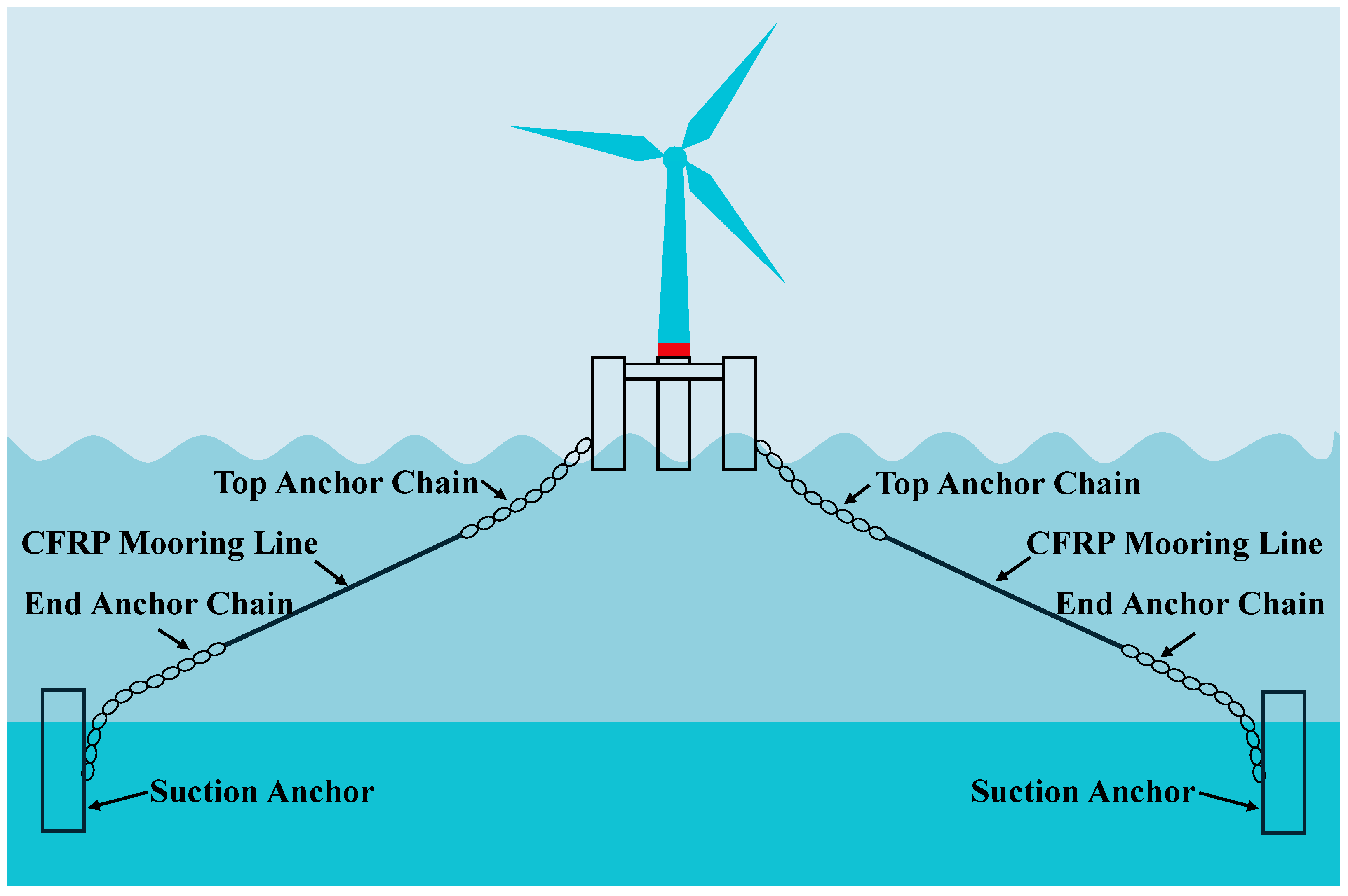
Existing mooring lines for floating offshore wind turbines can be categorized into two structural types: all-chain structures and “chain–cable–chain” composite structures. Compared to all-chain structures characterized by high self-weight and poor corrosion resistance, “chain–cable–chain” composite structures balance cost, performance, and environmental adaptability, and they are composed of an anchor chain at the seabed, a middle segment of synthetic or composite cable, and another chain section near the water surface. By leveraging the wear resistance and reliability of chains together with the elasticity and lightweight properties of the middle cable, the “chain–cable–chain” composite structure has become an efficient and economically optimized mooring option for floating offshore wind turbines. According to the material used for the middle cable segment, current “chain–cable–chain” structures can be divided into two types: the “chain–steel cable–chain” structure for water depths up to 1000 m and the “chain–polyester rope–chain” structure for depths beyond 1000 m. However, with the increase in water depth, floating wind turbines face challenges such as greater mooring loads, increased material usage for the submerged cable, and higher pretension near the structure. These factors pose significant difficulties for the positioning and operation of conventional mooring systems in deep water. In this study, based on the “chain–cable–chain” configuration, a novel mooring structure is proposed by replacing the traditional polyester rope or steel wire with lightweight, high-strength, fatigue-resistant, and corrosion-resistant CFRP cables. To be specific, the “chain–CFRP cable–chain” mooring structure consists of a top steel chain segment, a middle CFRP mooring cable, and a bottom steel chain segment, which is shown in Figure 1.

2.2. Design of CFRP Mooring Line System

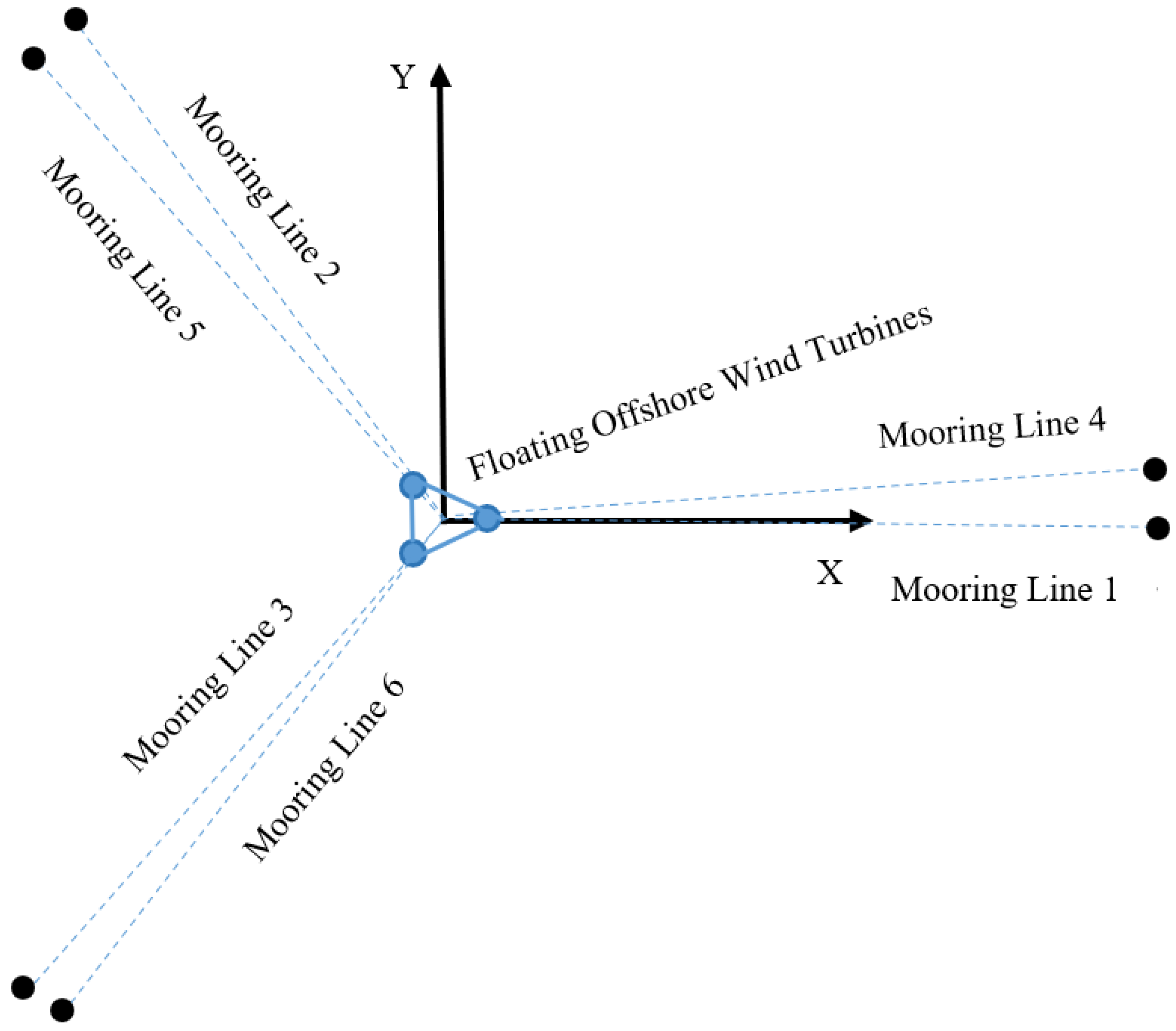
Compared to barge-type, tension-leg, and spar-type floating offshore wind turbines, semi-submersible platforms have become the preferred structural configuration due to their lower construction costs, easier installation, greater deployment flexibility, well-established technology, and applicability over a wider range of water depths. Taking the 5 MW triple-column semi-submersible floating wind turbine as example, a triangular six-line radial mooring pattern is adopted, as shown in Figure 2. Specifically, the triangular platform foundation is restrained by six CFRP mooring lines, which provide restoring forces to distribute the impact of wind, waves, and currents, thereby enhancing the overall stability of the turbine. The projected angles between the CFRP mooring lines in the three main directions on the horizontal plane are 120°, while the two adjacent lines within the same main direction are separated by 5°. The design parameters of the CFRP mooring lines and the coordinates of the mooring system are provided in Table 1 and Table 2, respectively.

3. Theoretical Fundamentals for Dynamic Analysis of Offshore Floating Wind Turbines

3.1. Motion Control Equation

The offshore floating wind turbine system comprises both rigid components (such as the floating platform) and flexible components (such as blades, the tower, and mooring lines), forming a coupled rigid–flexible multibody structure. Under combined environmental loads from wind, waves, and currents, complex dynamic interactions occur among these components. Therefore, it is necessary to establish a coupled rigid–flexible multibody dynamics model that integrates the blades, nacelle, tower, floating platform, and mooring lines. Based on multibody coupling theory and multibody dynamics, the fully coupled dynamic response of the offshore floating wind turbine system can be investigated by considering wind loads, current loads, and wave-induced forces. Due to the strong adaptability to complex geometries, convenience for multi-physics coupling analysis, and high computational efficiency, the three-dimensional potential flow theory has been widely used for analyzing the dynamic response of offshore floating structures, which assumes an inviscid and irrotational flow of an ideal fluid. In this paper, a coupled rigid–flexible multibody dynamics model of the floating offshore wind turbine is established using the three-dimensional potential flow theory. Taking into account the combined effects of wind, waves, and currents, the dynamic responses of the floating wind turbine and its mooring system are thoroughly analyzed.
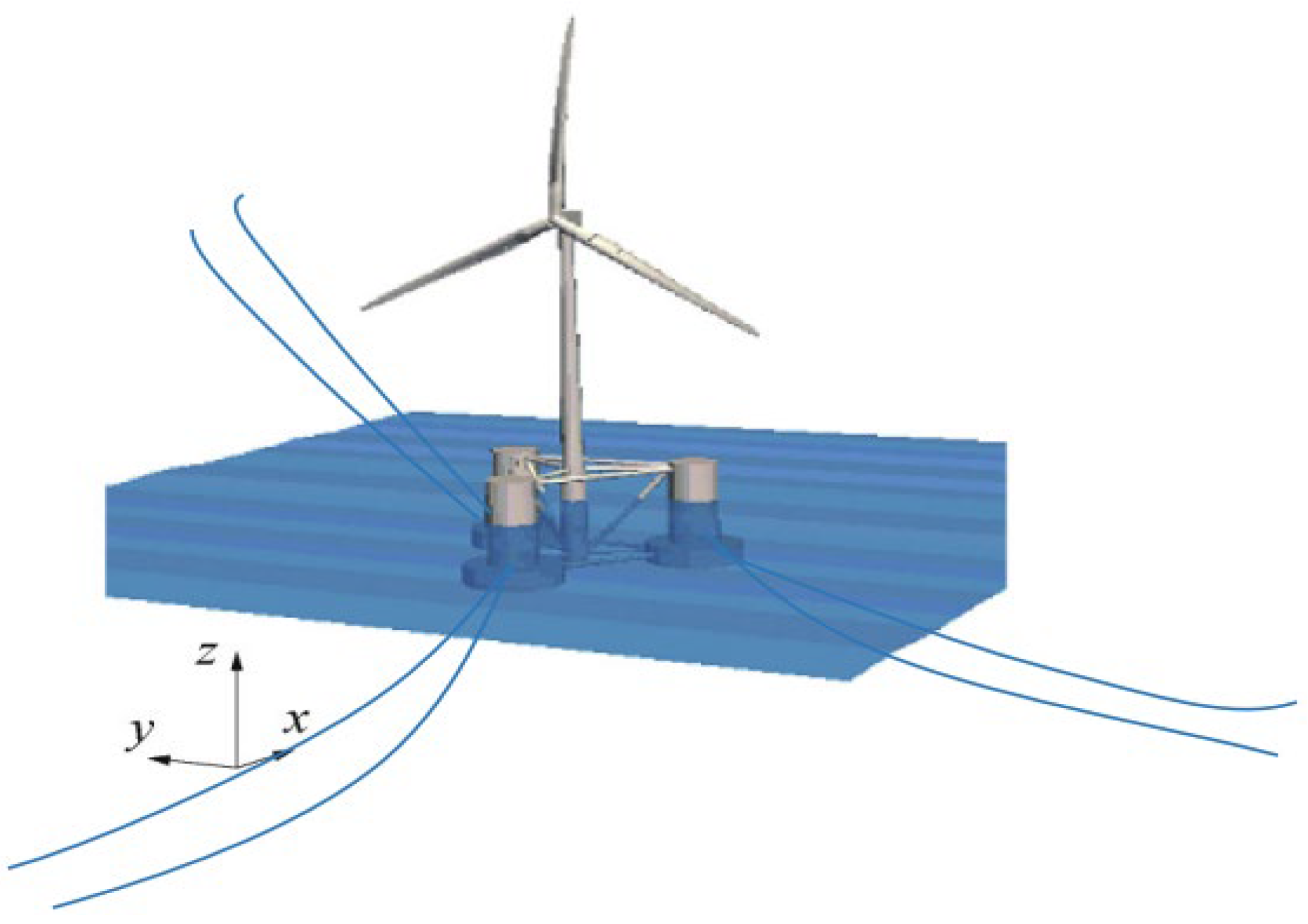
By integrating multibody dynamics, multi-physics coupling theory, and numerical analysis methods, a coupled rigid–flexible multibody dynamics model is established that incorporates the blades, nacelle, tower, floating platform, and mooring lines, as shown in Figure 3.
Assuming waves are harmonic (e.g., regular waves), the motion response of the offshore floating wind turbine exhibits the same frequency as the wave excitation force. Based on three-dimensional potential flow theory, the frequency-domain equations of motion for the offshore floating wind turbine are established as follows:
[ ω 2 ( M j k + A j k ( ω ) ) + i ω ( B j k ( ω ) + B v i s c ) + C j k ] X k ( ω ) = F e x c ( j ) ( ω ) + F a e r o ( j ) ( ω )
where ω is the motion frequency of the offshore floating wind turbine, Mjk denotes the structural mass matrix, Ajk represents the added mass matrix, Bjk is the radiation damping matrix, Bvisc refers to the empirically corrected viscous damping term, Cjk stands for the hydrostatic restoring matrix, Fexc indicates the wave excitation force, Faero corresponds to the aerodynamic load, and Xk(ω) signifies the frequency-domain response of the floating wind turbine system.
By applying the frequency response function method to analyze the frequency-domain equations of motion for the offshore floating wind turbine, the motion response function X(ω,t) under unit-amplitude harmonic wave excitation can be obtained, as shown in Equation (2), where D is the amplitude of the wave excitation force, K(ω) denotes the response amplitude operator (RAO) of the motion transfer function, t represents time, and ϕ is the initial phase angle.
X ω , t = D Re K ( ω ) exp [ i ( ω t + ϕ ) ]
Taking the wave nonlinearity and transient motion responses into account, the frequency-domain parameters are converted into the time domain via the impulse response function. Subsequently, the time-domain motion equations of the offshore floating wind turbine system under combined wind–wave–current loads are established based on d’Alembert’s principle, where Xk(t) denotes the time-domain response of the offshore floating wind turbine system; Ajk represents the infinite-frequency added mass; B is the damping matrix; C refers to the hydrostatic stiffness restoration matrix; R indicates the retardation function matrix (velocity impulse response matrix); τ stands for the motion time prior to the current time t; and F(t) is the total external force, which includes wave excitation force Fexc, aerodynamic load (or wind load) Faero, and mooring line restoring force Fmoor.
( M j k + A j k ) X ¨ k ( t ) + B X ˙ k ( t ) + C X k ( t ) + 0 t R ( t τ ) X ˙ k ( τ ) d τ = F ( j ) ( t )
F ( j ) ( t ) = F e x c ( j ) ( t ) + F a e r o ( j ) ( t ) + F m o o r ( j ) ( t )

3.2. Environmental Loading Condition

To ensure the safety and reliability of offshore floating wind turbines, this study investigates their dynamic responses under various sea conditions. The most unfavorable environmental load case is considered, in which wind, waves, and currents all act in the same direction—specifically along the positive x-axis at 0°. The motion responses and mooring tensions of the floating wind turbine system under combined wind–wave–current loads are analyzed for both normal operating conditions and a once-in-50-year extreme sea state. The wind and wave loads are simulated using the API wind spectrum model and the JONSWAP wave spectrum model, respectively. The relevant parameters are listed in Table 3.
Under operating sea conditions, the wind load acting on the wind turbine blades, tower, and the substructure above the foundation is considered. In extreme sea conditions, when the turbine is in a feathered shutdown state, the wind load on the rotor, tower, and the substructure above the foundation is taken into account. As shown in Equation (5), the wind load is calculated using the thrust coefficient method, where ρ is the air density, AR is the swept area of the blades, Cs is the shape coefficient, and Ch is the height coefficient.
F a e r o = 1 2 ρ a A R C s C h U 0 2
Based on the Morison equation and taking into account the coupling effects of waves and currents, the wave and current loads on the offshore floating wind turbine are calculated as shown in Equation (6), where CD is the drag coefficient, ρw is the density of seawater, Ap is the projected area of the offshore floating wind turbine perpendicular to the flow direction, and Vf is the total flow velocity considering the coupling effect of waves and currents.
F e x c = 1 2 C D ρ w A p V f 2

3.3. CFRP Mooring System Design and Dynamic Analysis Workflow for Offshore Floating Wind Turbines

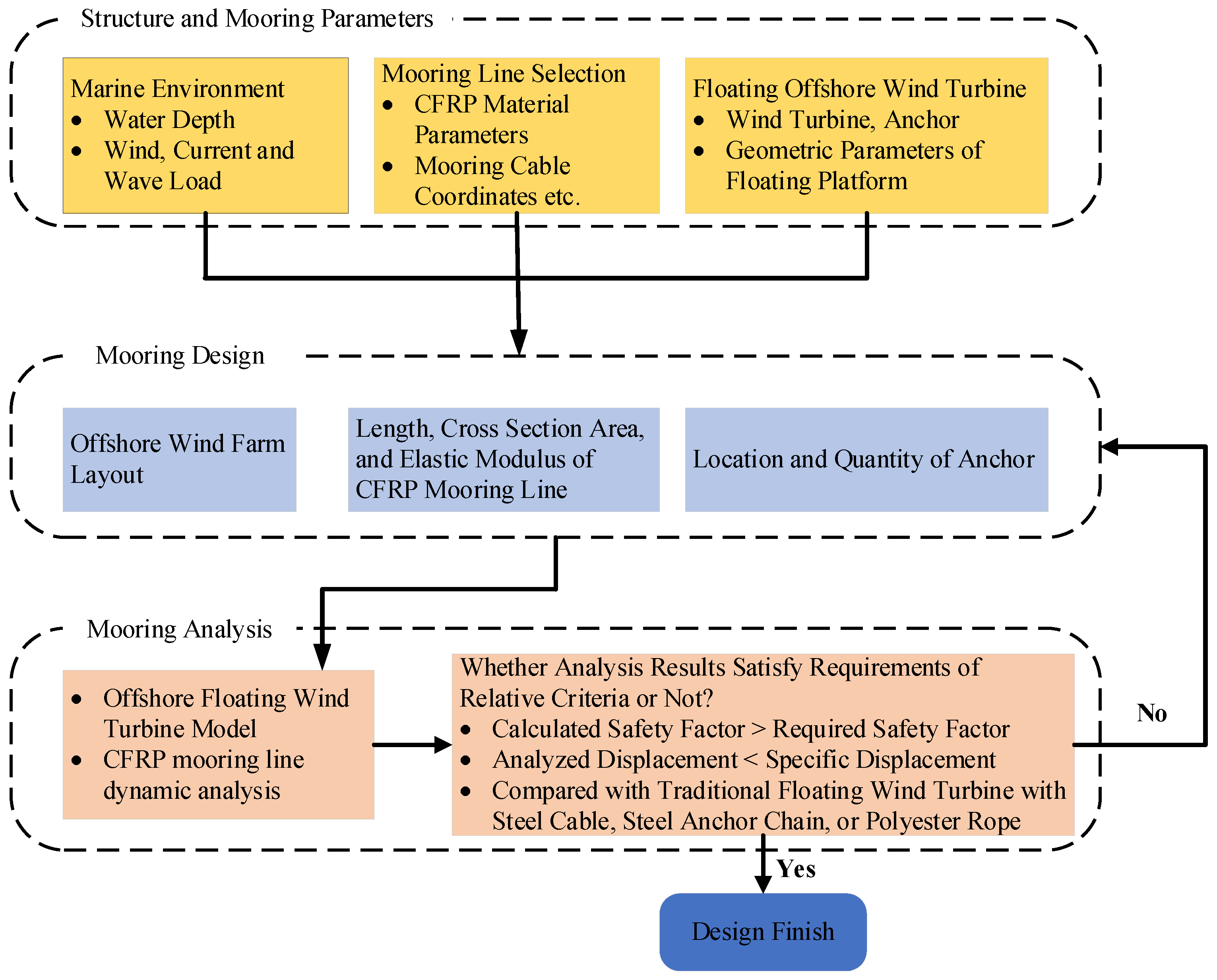
The procedure for the mooring design and dynamic analysis of an offshore floating wind turbine with CFRP mooring lines is illustrated in Figure 4. The specific steps are as follows:
(1) The structural parameters of the offshore floating wind turbine and the mooring system parameters should be determined, including the geometric parameters of the floating wind turbine, mooring line coordinates, environmental load cases, etc., and based on these parameters, a numerical simulation model is established.
(2) According to static and dynamic stiffness models, traditional mooring lines such as chains, steel cables, and polyester ropes are replaced with CFRP cables. After that, the structural parameters of the CFRP mooring line are preliminarily designed, including length, cross-sectional area, elastic modulus, etc.
(3) Based on the preliminary design from Step (2), a numerical simulation analysis of the dynamic performance of the offshore floating wind turbine moored with CFRP mooring lines is conducted. Then, whether the simulation results meet the requirements is checked. If not, Step (2) is repeated; if yes, the design is completed, and the numerical simulation results are output.

4. Results and Discussion

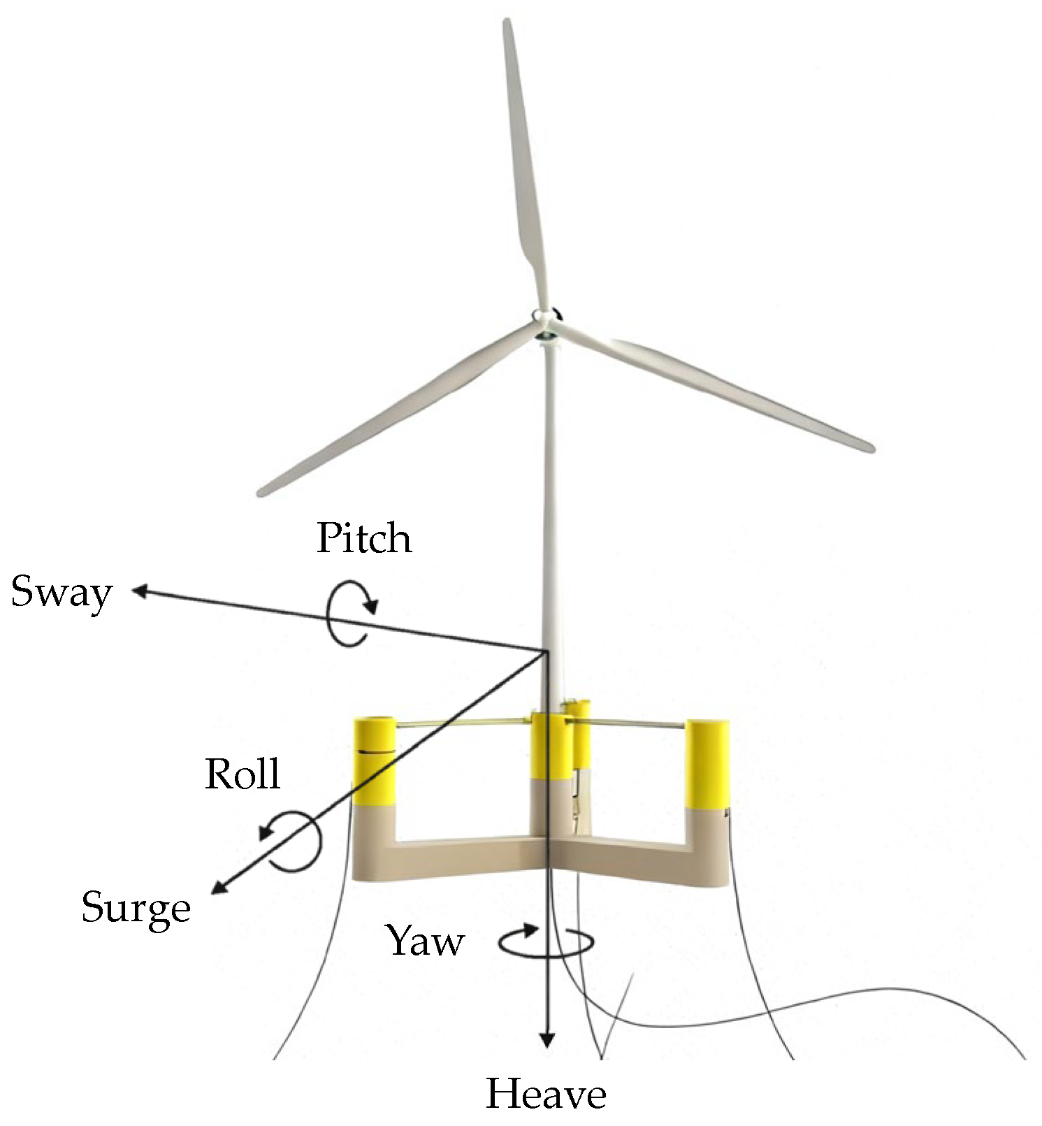
Under the combined loads of wind, waves, and currents, an offshore floating wind turbine undergoes complex three-dimensional spatial motions. As a rigid body, its motion in three-dimensional space can be decomposed into six independent degrees of freedom, comprising three translational motions (surge, heave, sway) and three rotational motions (roll, pitch, yaw), as illustrated in Figure 5.

4.1. Free Decay Response Analysis of a 5 MW Offshore Floating Wind Turbine in Still Water

To understand and evaluate the fundamental hydrodynamic characteristics of an offshore floating wind turbine with CFRP mooring lines in a wave-free environment, a free decay response analysis in still water was conducted in this study. The design parameters of mooring systems with different materials, including steel chain, steel cable, polyester rope, and CFRP mooring line, are provided in Table 4.
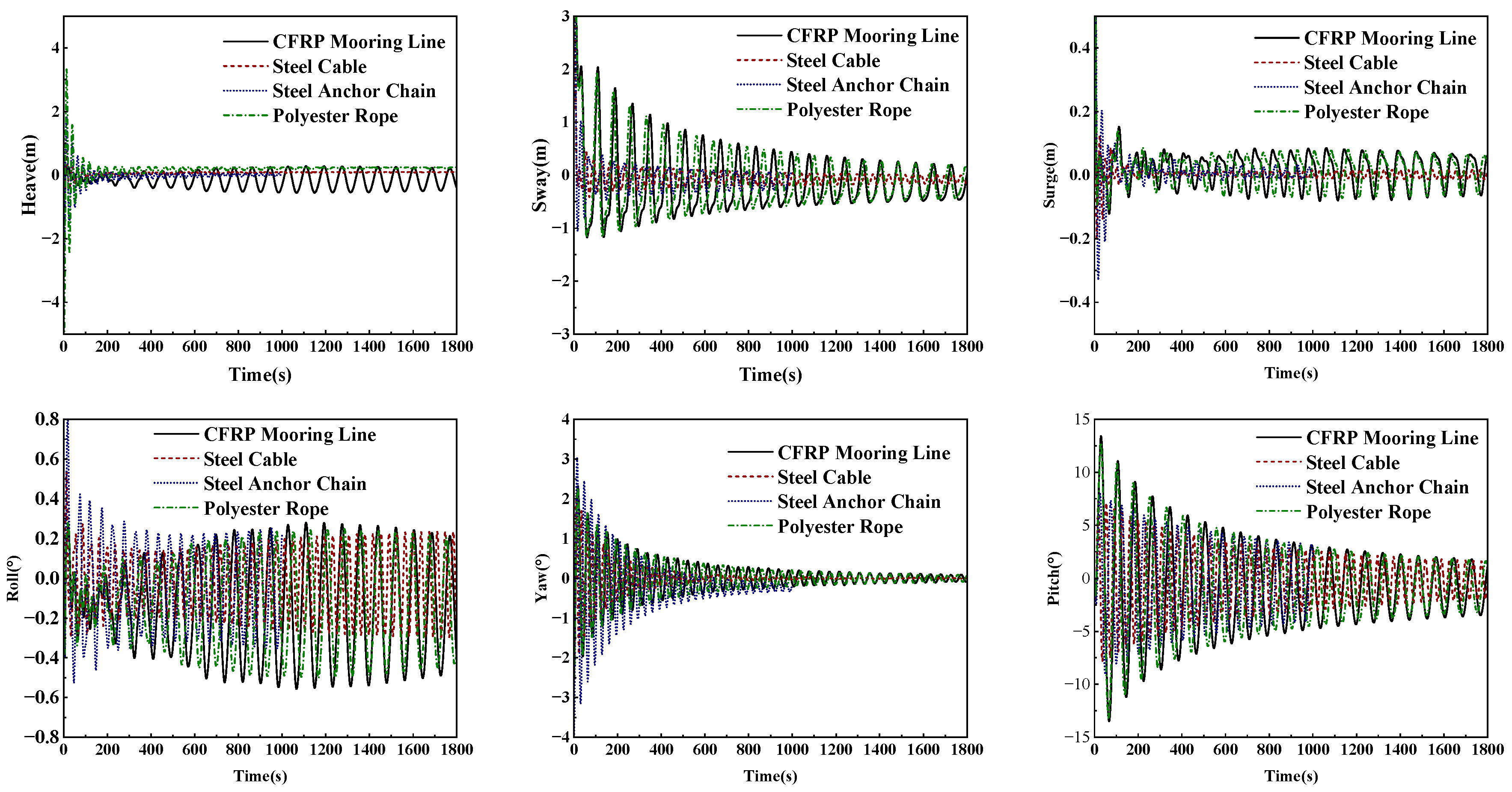
Taking the initial displacement of the floating structure into consideration, a free decay response analysis of an offshore floating wind turbine with steel chains, steel cable, polyester ropes, and CFRP mooring lines was comparatively conducted without wind, waves, or currents. The initial heave displacement was set to 2 m, while the initial displacements in roll, pitch, and yaw were set to 0°. The results of the free decay response analysis are presented in Figure 6. As shown in Figure 6, the surge, sway, roll, and yaw responses of the floating wind turbine are relatively small under still-water conditions, while the heave and pitch responses are more significant. However, the free decay responses gradually diminish as time progresses, and the steady-state motions in all six degrees of freedom eventually stabilize near the zero position. Compared to traditional steel wire ropes, steel chains, and polyester ropes, the CFRP mooring system exhibits larger free decay responses and a longer decay duration. According to equations of free vibration for multi-degree-of-freedom (MDOF) systems, the magnitude and duration of the decay responses for mooring systems made of different materials are primarily influenced by the restoring stiffness and effective mass of the mooring system. Owing to lower restoring stiffness and lighter weight, the CFRP mooring lines result in a longer natural period and lower natural frequency of the system. Therefore, the CFRP mooring system demonstrates relatively larger free decay responses and an extended decay duration. The free decay response analysis of the offshore floating wind turbine in still water can obtain essential dynamic characteristics of various mooring systems, which provides a foundation for further time-domain analysis of the floating wind turbine’s dynamic behavior.

4.2. Time-Domain History Response Analysis of Offshore Floating Wind Turbine with CFRP Mooring Lines

To validate the feasibility of the mooring design for the offshore floating wind turbine with CFRP cables, the time-domain history response analysis of a 5 MW triple-column semi-submersible floating wind turbine moored with steel chain, steel cable, polyester rope, and CFRP mooring lines was conducted under different sea conditions.

4.2.1. Time-Domain History Response Analysis of Offshore Floating Wind Turbine Under Operating Sea Conditions

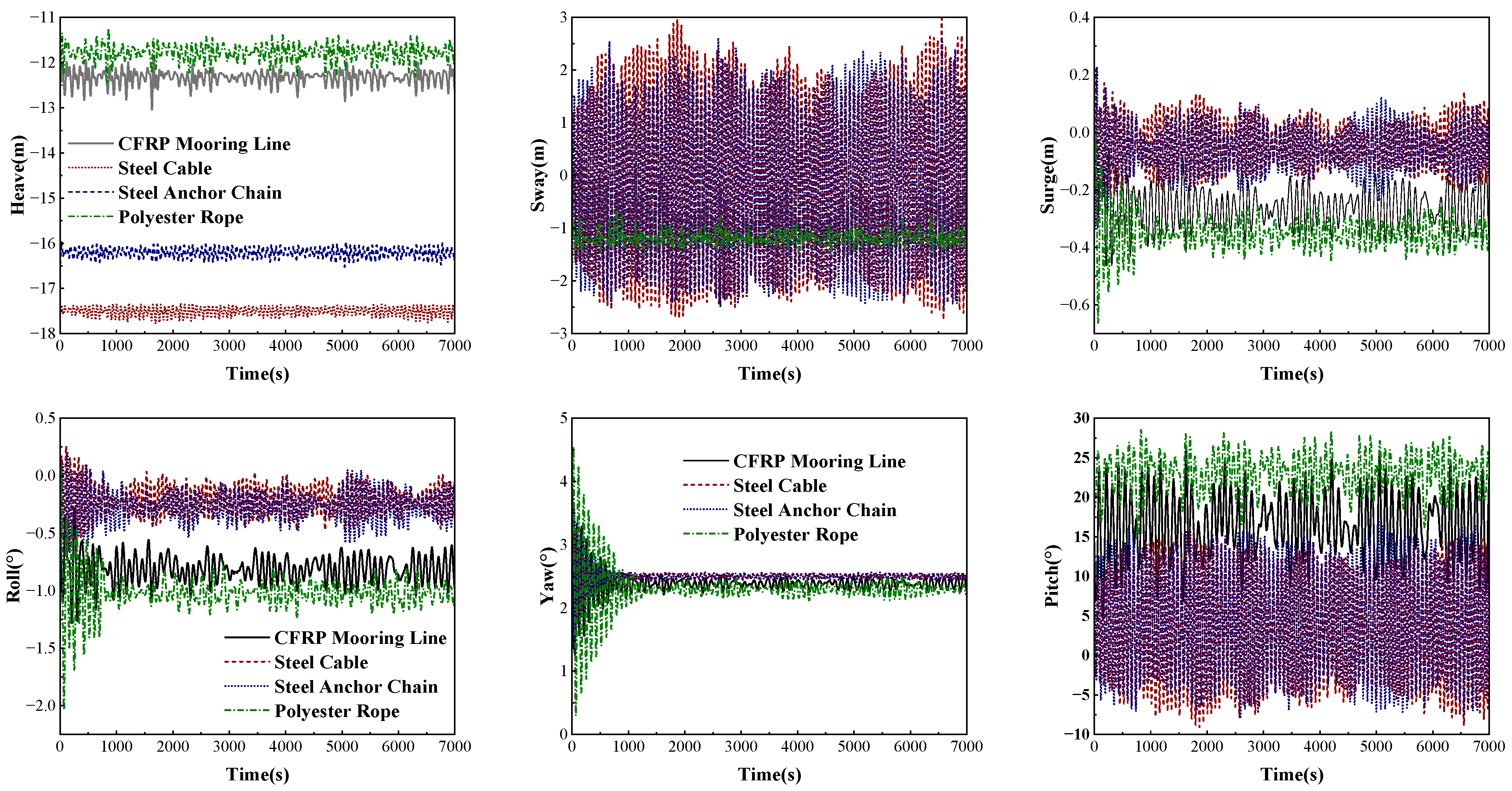
The motion of an offshore floating wind turbine primarily includes horizontal movements represented by surge and sway, vertical movement represented by heave, and rotational motions represented by pitch, roll, and yaw. Under normal operating sea conditions, the time-history displacement responses of the floating wind turbine with different types of mooring lines are shown in Figure 7 and Table 5. As shown in Figure 7 and Table 5, the motion responses of surge, sway, roll, and yaw of the floating wind turbine moored with different types of mooring lines are relatively small. In contrast, the heave and pitch motions governed by wave actions exhibit significantly larger amplitudes due to the considerable increase in wave height amplifying their wave-frequency responses. Compared with traditional mooring lines, the motion responses of the floating wind turbine with CFRP mooring lines lie between those of the steel chain and polyester rope systems, owing to its elastic modulus being lower than that of steel wire ropes and chains but higher than that of polyester ropes. The maximum displacement of the floating wind turbine with CFRP mooring lines is 13.05 m (6% of the water depth), which satisfies the maximum allowable horizontal displacement requirement (15–25% of water depth) specified in API RP 2FP1 [31]. It has been demonstrated that the CFRP mooring system can ensure the safe operation of the offshore floating wind turbine.
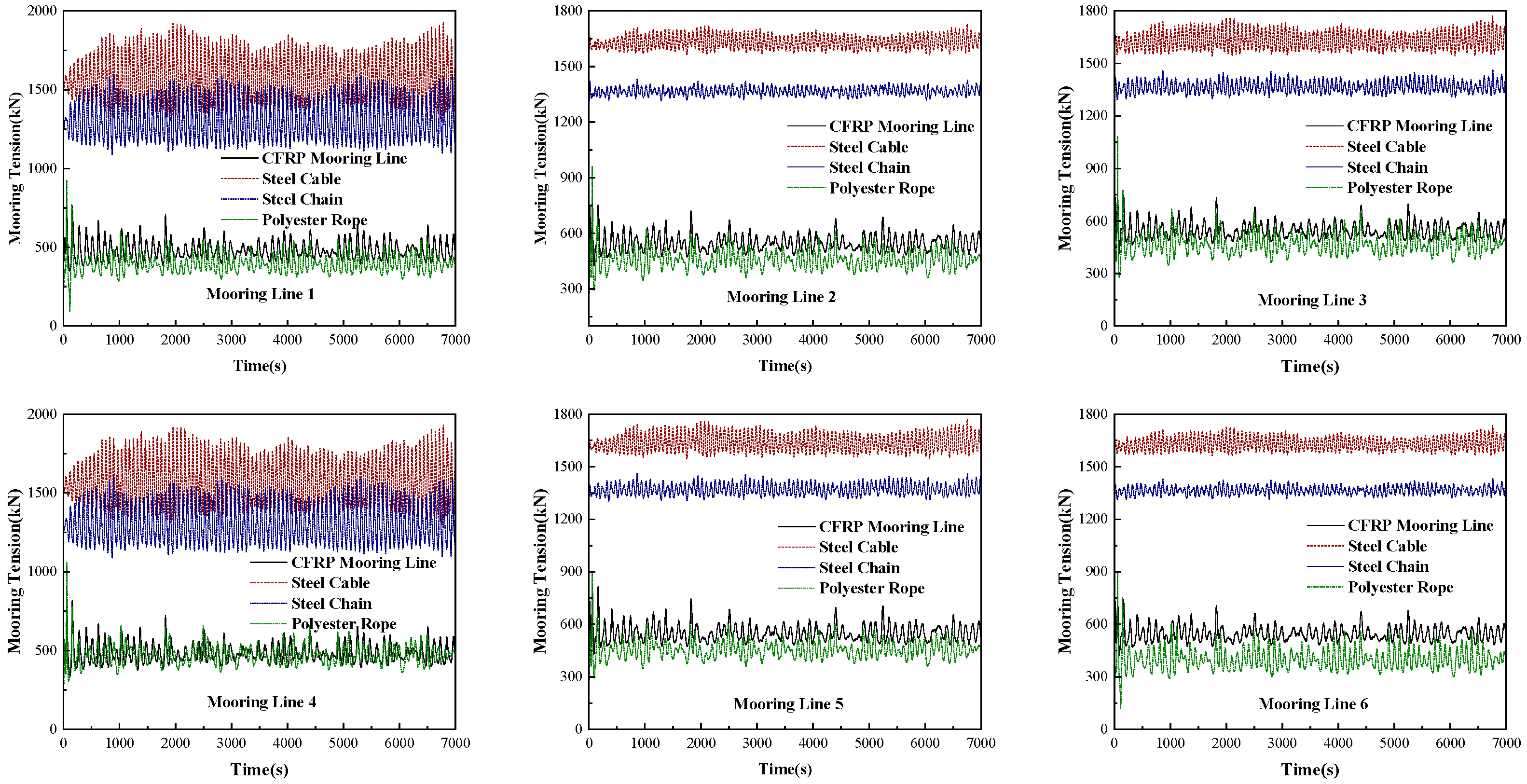
As shown in Figure 8 and Table 6, the variations in mooring tensions for the offshore floating wind turbine with different mooring lines under operating sea conditions are compared. Due to the high elastic modulus, large axial stiffness, and small deformation range, the steel cable exhibits the highest mooring force under operating conditions. Although the steel chain has a lower elastic modulus and axial stiffness and a significant self-weight, its catenary configuration provides partial gravitational restoring force, sharing some of the load. As a result, the mooring tension of the steel chain falls in the medium range. Compared to steel cables and steel chains, CFRP mooring lines have a lower elastic modulus and ductility. Owing to their lightweight and high-strength properties, CFRP mooring lines significantly reduce gravitational loads. Under operating sea conditions, the mooring force of CFRP mooring lines is noticeably smaller than that of steel wire ropes and steel chains. With the lowest elastic modulus but high ductility, polyester ropes can absorb energy through elastic deformation, which can reduce the peak mooring force and make the mooring tension of polyester ropes the smallest among all the materials.
It can be seen from Table 6 that CFRP mooring lines exhibit the highest safety factor (all exceeding 4.30) under the same working sea conditions due to their high specific strength. Compared to mooring lines made of other materials, CFRP mooring lines demonstrate the highest operational safety and reliability. Additionally, the maximum mooring tension of CFRP mooring lines is 836 kN, which meets the specifications of API RP 2SM [31].

4.2.2. Time-Domain History Response Analysis of Offshore Floating Wind Turbine Under Extreme Sea Conditions

With deterioration of the Earth’s ecosystem environment, natural disasters are taking place more frequently in recent years. In particular, deep-sea areas are experiencing increasingly strong winds and high waves, which raises the probability of extreme sea conditions. Therefore, it is of important scientific significance and practical value that the time-history response of offshore floating wind turbines with CFRP mooring lines under extreme sea conditions is analyzed and studied. Based on the scenario of once-in-50-year extreme sea conditions and considering the fracture of Mooring Line #1, a comparative analysis of the time-domain response histories of offshore floating wind turbines with mooring lines made of different materials was conducted in this paper.
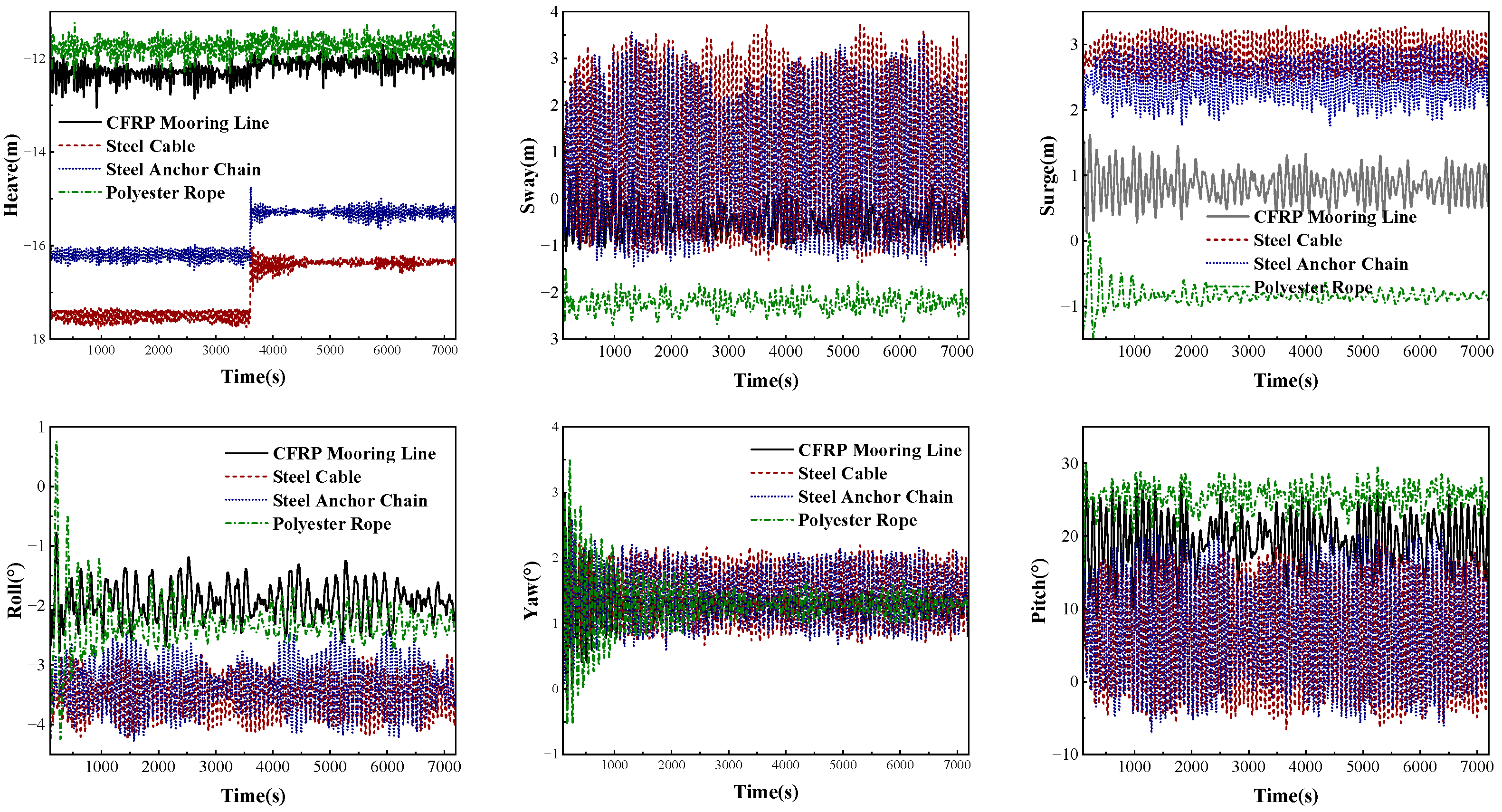
The displacement time-history response results of offshore floating wind turbines with different mooring materials under extreme sea conditions are shown in Figure 9 and Table 7. Compared to the operating sea conditions, the displacement response of the offshore floating wind turbine under extreme sea conditions with broken mooring lines increases to varying degrees. Depending on the extent of the displacement change, the changes in the displacement response of the offshore floating wind turbine can be categorized into two types: steady-state offset and exacerbated dynamic response. As shown in Figure 9 and Table 7, the displacement responses in surge, sway, roll, yaw, and pitch show minor changes, which belongs to the steady-state offset. As mooring systems consist of multiple mooring lines, redundancy design is adopted in offshore floating wind turbines. Although the fracture of one mooring line reduces the overall stiffness, the remaining lines can provide considerable restraining force, resulting in a relatively small decline in the stability of the offshore floating wind turbine. Therefore, the floating wind turbine undergoes steady-state changes in surge, sway, roll, yaw, and pitch directions, whose displacement response variations are small. Although the heave response of the offshore floating wind turbine relies less on the mooring stiffness, the fracture of the mooring line leads to a decrease in the total damping of the system. With the weakness of the energy dissipation capacity of the heave motion, the floating wind turbine is more sensitive to wave excitation force components close to its natural heave frequency. Under low-damping conditions, resonant responses can be easily triggered. As result, a sharp increase in the heave displacement amplitude is caused, which induces an exacerbated dynamic response in heave.
Under the same extreme sea conditions, the higher elastic modulus of steel cables and chains, compared to CFRP and polyester ropes, results in a stiffer overall mooring system response. After the failure of a mooring line, the movement of the floating offshore wind turbine relies on the geometric configuration changes (including displacement and angle variations, etc.) in the remaining steel cables and steel anchor chains. This results in greater displacement of the floating offshore wind turbine moored with steel cables/anchor chains than that moored with CFRP mooring lines/polyester ropes.
The low elastic modulus of CFRP mooring lines makes a relatively more uniform tension distribution among the mooring lines under normal operating conditions. When one mooring line fails, its tension is redistributed among the remaining lines. Compared to steel cable and steel anchor chain systems with a less uniform tension distribution, the maximum tension increase caused by tension redistribution in the uniformly tensioned CFRP mooring system is relatively small. Due to their high elasticity and low modulus, the remaining CFRP mooring lines can accommodate the tension increase through elongation without immediate failure or causing excessive displacement of the floating offshore wind turbine.
For polyester ropes with a lower elastic modulus, larger elastic elongation, and lower tension level, the strain energy released by the slackening of the polyester rope is relatively small when one mooring line fails. Moreover, the remaining polyester ropes can absorb part of the displacement required for the motion response of the floating offshore wind turbine through further elastic elongation. In other words, part of the motion of the floating offshore wind turbine will convert into additional elongation of the remaining polyester ropes. Therefore, the displacement time-history response of polyester ropes under extreme sea conditions is relatively small.
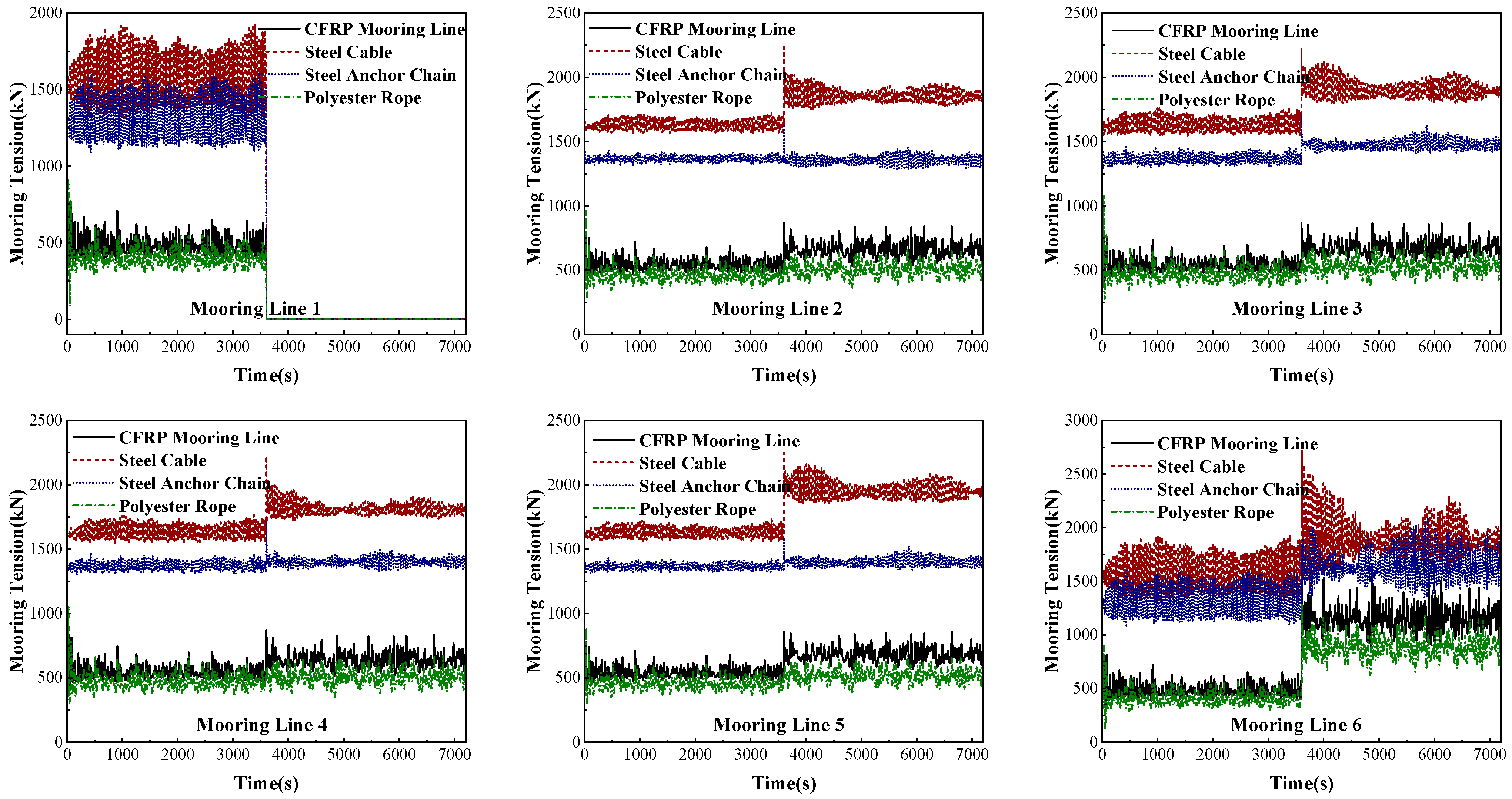
As shown in Figure 10 and Table 8, the variations in mooring tension for the offshore floating wind turbine with different mooring materials under extreme sea conditions are illustrated. At t = 3600 s, the mooring tensions in the remaining lines increase sharply when Mooring Line 1 fractures. Due to their high axial stiffness and limited elongation capacity, the steel cables and steel anchor chains establish a high-rigidity constraint system for the floating wind turbine. When one mooring line fails, the load originally borne by that line is instantaneously redistributed to the remaining lines. Consequently, the mooring tension in the remaining steel cables and steel anchor chains increases abruptly to provide sufficient restoring force for the floating wind turbine. As a result, the mooring tension in steel cables and steel anchor chains exhibits a substantial increase under extreme sea conditions.
In contrast, CFRP mooring lines with lower stiffness can absorb a significant portion of the suddenly increased load through substantial elastic elongation. Meanwhile, the intact CFRP mooring lines make the floating wind turbine move in the direction opposite to the broken line with a large offset displacement, which can effectively dissipate the surge in fracture energy and enable the system to reach a new equilibrium under a more relaxed geometric configuration. The above changes in geometry maintain relatively stable tension levels in the system. Although the tension in the remaining CFRP mooring lines still experiences a sudden increase, the magnitude is relatively small due to their low stiffness and large offset displacement.
In addition to the low stiffness and large deformation capacity, polyester ropes exhibit significant nonlinear stiffness behavior, which indicates low stiffness under low tension, but they gradually stiffen as the tension increases. Thus, the load transfer causes a sharp increase in tension in the remaining lines at the moment of a single polyester line failure. However, the remaining polyester ropes undergo considerable elastic deformation due to their low initial stiffness, which effectively absorbs the peak tension impact. As the deformation increases, the stiffness of the polyester ropes gradually rises. This leads to an increase in the mooring restoring force, which can avoid an abrupt tension surge when the lines resist the impact load in a rigid manner. Moreover, the high material damping of polyester ropes makes them able to dissipate more energy through internal friction under dynamic loading, particularly during the intense adjustment process after a fracture.
Under extreme sea conditions, the mean and peak mooring tensions are highest for steel cables, followed by steel anchor chains. Both polyester rope and CFRP mooring lines exhibit relatively lower mean and peak tensions. Due to their light weight and high strength, the safety factors of CFRP mooring lines are the highest, which are all greater than 1.67 and meet the requirements of API RP 2SM [31]. This indicates that CFRP mooring lines exhibit strong operational stability and safety under extreme sea conditions, proving their feasibility for application in floating offshore wind turbines.

5. Conclusions

Based on the chain–cable–chain configuration, this paper proposes a “chain–CFRP cable–chain” mooring system for an offshore floating wind turbine. Using a multibody coupling model and multibody dynamics theory, the mooring design and dynamic performance of the floating wind turbine with CFRP mooring lines were investigated. The main conclusions are as follows:
(1) The mooring system composed of a top steel chain segment, a middle CFRP cable section, and a bottom steel chain segment can effectively combine the wear resistance and installation convenience of steel chains with the lightweight and high-strength properties of CFRP material, which ensures both the safety and economic efficiency of the mooring system for offshore floating wind turbines.
(2) Under still-water conditions, the heave and pitch responses of the floating wind turbine moored with different materials are significant. Due to the low restoring stiffness and light weight, the CFRP mooring system exhibits a larger free decay response and a longer decay duration.
(3) Under operating sea conditions, the motion response and mooring tension of the floating wind turbine with CFRP cables fall between those of systems using steel chains and polyester ropes due to the low elastic modulus and ductility, which can ensure the safe operation of the floating wind turbine.
(4) Under extreme sea conditions, the dynamic response of the floating wind turbine in heave becomes more pronounced. The low stiffness and large offset displacement of the CFRP mooring lines can effectively mitigate sharp changes in displacement and tension caused by cable failure. This indicates that the CFRP mooring lines can achieve integrated performances in offshore floating wind turbines as a replacement for traditional mooring systems.
Author Contributions

Conceptualization, Y.Y. and R.X.; methodology, Y.Y. and M.L.; software, R.X. and J.S.; validation, Y.Y., Y.L., and X.W.; formal analysis, Y.Y.; investigation, Y.Y. and W.S.; resources, Y.Y. and H.L.; data curation, Y.Y.; writing—original draft preparation, Y.Y. and R.X.; writing—review and editing, Y.Y., M.L., and X.W.; visualization, Y.Y. and J.S.; supervision, Y.Y. and Y.L.; project administration, Y.Y. and W.S.; funding acquisition, Y.Y. and J.S. All authors have read and agreed to the published version of the manuscript.

Funding

This research was funded by National Natural Science Foundation of China (grant number 51808265 and 52508262), Natural Science Foundation of the Jiangsu Higher Education Institutions of China (grant number 18KJB560005), Key Research and Development of Shandong Province (grant number 2019GSF111013), Postgraduate Research & Practice Innovation Program of Jiangsu Province (grant number SJCX24_2548, SJCX24_2556, KYCX24_4135, KYCX24_4138), Jiaxing Public Welfare Research Program Project (grant number 2024AY10011), Science and Technology Plan Project of Zhejiang Provincial Market Supervision and Administration Bureau in 2025 (grant number ZD2025021), Natural Science Foundation of Jiangsu Province (grant number BK20241015), and MTIC-JUST Joint Innovation Center Development Fund (grant number 2025MTIC-JUST005).

Data Availability Statement

The data presented in this study are available on request from the corresponding author.

Conflicts of Interest

The authors declare no conflicts of interest.

References

  1. Jackson, D.; Shepheard, B.; Kebadze, E. CFRP Mooring Lines for MODU Applications. In Proceedings of the Offshore Technology Conference, Houston, TX, USA, 2–5 May 2005. [Google Scholar]
  2. Eduardo, A.W.M.; Laris, V.S.; Carlos, A.C.J.; Felipe, F.L.; Sandro, C.A. Numerical and Experimental Analysis of Tensile and Bending Behavior of CFRP Cables. Polym. Polym. Compos. 2017, 25, 643–650. [Google Scholar]
  3. Luz, F.F.; de Menezes, E.W.; Cimini, C.A.; Amico, S.C. Numerical Analysis of Carbon Fiber Cables for Mooring Lines Under Tensile and Bending Loading. Int. J. Offshore Polar Eng. 2018, 28, 387–392. [Google Scholar] [CrossRef]
  4. Amaechi, C.V.; Gillett, N.; Agbomerie, C.O.; Hou, X.; Ye, J. Composite risers for deep waters using a numerical modelling approach. Compos. Struct. 2019, 210, 486–499. [Google Scholar] [CrossRef]
  5. Zhang, Y.; Guo, Z.; Zhao, H.; Ma, G.; Zhang, F. Analysis of torsional instability and reliability of marine flexible pipelines. Ocean Eng. 2021, 228, 701–709. [Google Scholar] [CrossRef]
  6. Zhang, Y.; Zhang, H.; Xia, R.; Jiang, S.; Wang, F. Reliability analysis of carbon fiber rod-reinforced umbilical cable under tension using an improved sampling method. Pet. Sci. 2024, 21, 2769–2778. [Google Scholar] [CrossRef]
  7. Urs, M. Proposal for a carbon fiber reinforced composite bridge across the Strait of Gibraltar at its narrowest site. Proc. Inst. Mech. Eng. 1987, 201, 73–78. [Google Scholar]
  8. Yang, Y.; Fahmy, M.F.M.; Guan, S.; Pan, Z.; Zhan, Y.; Zhao, T. Properties and applications of FRP cable on long-span cable-supported bridges: A review. Compos. Part B Eng. 2020, 190, 107934. [Google Scholar] [CrossRef]
  9. Shi, J.; Guo, R.; Xian, G. Fatigue performance of kiloton CFRP cable after hygrothermal and freeze–thaw cycles. Int. J. Fatigue 2025, 200, 1031–1042. [Google Scholar] [CrossRef]
  10. Jiang, Z.; Fang, Z.; Fang, C.; Li, Q.; Wang, Z. Experimental investigation on high-temperature creep behavior of carbon fiber reinforced polymer cable. Compos. Struct. 2022, 291, 3301–3315. [Google Scholar] [CrossRef]
  11. Wang, M.; Chen, B.; Jiang, H.; Zhuge, P. A Study on the Impact of Temperature on the Anchoring Durability of Carbon-Fiber-Reinforced Polymer Cables. Materials 2025, 18, 411–417. [Google Scholar]
  12. Feng, B.; Wang, X.; Wu, Z. Static and Fatigue Behavior of Multitendon CFRP Cables with Integrated Anchorages. J. Compos. Constr. 2019. [Google Scholar] [CrossRef]
  13. Yang, Y.; Zhou, Z.; Guan, Y.; Shi, J.; Zhan, Q.; Fahmy, M.F.M.; Wu, B. Nonlinear Coupled Vibration Behavior of BFRP Cables on Long-Span Cable-Stayed Bridges under Parametric Excitation. Buildings 2023, 13, 3082. [Google Scholar] [CrossRef]
  14. Yang, Y.; Wang, X.; Wu, Z. Experimental Study of Vibration Characteristics of FRP Cables for Long-Span Cable-Stayed Bridges. J. Bridge Eng. 2015, 20, 04014074. [Google Scholar] [CrossRef]
  15. Zhang, X.; Ying, L. Wind-resistant performance of cable-supported bridges using carbon fiber reinforced polymer cables. Wind Struct. 2007, 10, 121–133. [Google Scholar] [CrossRef]
  16. Liang, R.; Zhi, F.; Kai, W. Design and behavior of super-long span cable-stayed bridge with CFRP cables and UHPC members. Compos. Part B Eng. 2019, 164, 72–81. [Google Scholar]
  17. Liu, Y.; Gu, M.; Liu, X.; Tafsirojjaman, T. Life-Cycle Cost Analysis of Long-Span CFRP Cable-Stayed Bridges. Polymers 2022, 14, 1740. [Google Scholar] [CrossRef]
  18. Meier, U. Carbon Fiber Reinforced Polymer Cables: Why? Why Not? What If? Arab. J. Sci. Eng. 2012, 37, 399–411. [Google Scholar] [CrossRef]
  19. Dehmous, H.; Hélène, W. Multi-scale reliability analysis of composite structures-Application to the Laroin footbridge. Eng. Fail. Anal. 2011, 18, 988–998. [Google Scholar] [CrossRef]
  20. Christoffersen, J.; Hauge, L.; Bjerrum, J. Footbridge with Carbon-Fibre-Reinforced Polymers, Denmark. Struct. Eng. Int. 1999, 9, 254–256. [Google Scholar]
  21. Qi, L.; Bai, J.; Wu, H.; Xu, G.; Xiong, H.; Yang, Y. The first engineering application of 10MN CFRP cables in cable-stayed bridge in China. Structures 2024, 68, 9901–9916. [Google Scholar] [CrossRef]
  22. Yang, Y.; Wang, X.; Wu, Z. Evaluation of the Static and Dynamic Behaviors of Long-Span Suspension Bridges with FRP Cables. J. Bridge Eng. 2016, 21, 801–810. [Google Scholar] [CrossRef]
  23. Zhuge, P.; Qiang, S.; Hou, S.; Liu, M. Research on Bending Performance of CFRP Main Cable in Saddle of Suspension Bridge. China J. Highw. Transprot 2011, 24, 57–62. [Google Scholar]
  24. Hou, S.; Zhuge, P.; Qiang, S.; Li, C. Experimental Investigation of Friction Properties between CFRP Main Cable and Saddle of Suspension Bridge. J. Southwest Jiaotong Univ. 2011, 46, 391–397. [Google Scholar]
  25. Hou, S.; Qiang, S.; Liu, M.; Zhuge, P. Experimental investigation of tribological perperties between CFRP main cable and clamp. J. Shenzhen Univ. Sci. Eng. 2012, 29, 201–206. [Google Scholar]
  26. Zhuge, P.; Zhang, Z.; Wang, S.; Ding, Y.; Qiang, S. Anti-slip performance of interface between carbon fiber-reinforced plastic main cable and cable clamp for large-span suspension bridges. J. Southwest Jiaotong Univ. 2014, 49, 208–212. [Google Scholar]
  27. Meier, U.; Winistoerfer, A.U.; Haspel, L. World’s first large bridge fully relying on carbon fiber reinforced polymer hangers. In Proceedings of the SAMPE Rurope Conference, Amsterdam, The Netherlands, 30 September–1 October 2020. [Google Scholar]
  28. Qin, W.; Gao, H.; Xi, Z.; Feng, P.; Li, Y. Shaking table experimental investigations on dynamic characteristics of CFRP cable dome. Eng. Struct. 2023, 281, 115748. [Google Scholar] [CrossRef]
  29. Zhang, Z.; Wang, X.; Zhang, X.; Zhou, C.; Wang, X. Dynamic responses and mooring line failure analysis of the fully submersible platform for floating wind turbine under typhoon. Eng. Struct. 2024, 301, 117334. [Google Scholar] [CrossRef]
  30. Zhong, F.; Lian, Y.; Zheng, J.; Chen, W.; Ma, G.; Solomon, C.S.Y. Effects of the shared lines with different materials on the mooring response of the floating wind farm. Chin. J. Ship Res. 2024, 19, 59–70. [Google Scholar]
  31. API RP 2SM; Recommended Practice for Design, Analysis, and Maintenance of Moorings for Floating Production Systems: API RP 2FP1. American Petroleum Institute: Washington, DC, USA, 1993.
Figure 1. “Chain–CFRP cable–chain” mooring structure.
Buildings 15 03734 g001
Figure 2. CFRP mooring line system.
Buildings 15 03734 g002
Figure 3. Coupled rigid–flexible multibody dynamics model.
Buildings 15 03734 g003
Figure 4. Design and dynamic analysis procedure for an offshore floating wind turbine with CFRP mooring lines.
Buildings 15 03734 g004
Figure 5. Offshore floating wind turbine with 6 degrees of freedom.
Buildings 15 03734 g005
Figure 6. Free decay responses of offshore floating wind turbine with mooring lines of different materials.
Buildings 15 03734 g006
Figure 7. Displacement time history of mooring lines of different materials under operating sea conditions.
Buildings 15 03734 g007
Figure 8. Mooring tensions of mooring lines of different materials under operating sea conditions.
Buildings 15 03734 g008
Figure 9. Displacement time history of mooring lines of different materials under extreme sea conditions.
Buildings 15 03734 g009
Figure 10. Mooring tensions of mooring lines of different materials under extreme sea condition with Mooring Line 1 failing after 3600 s.
Buildings 15 03734 g010
Table 1. Design parameters of the CFRP mooring lines.
ComponentsLength (m)Diameter (mm)Weight (kg/m)Elastic Modulus (GPa)Tensile Strength (MPa)Axial Stiffness (kN)
Top Anchor Chain58.576.6113.3519012807.53 × 105
CFRP Cable99015411.915024002.79 × 106
End Anchor Chain131.576.6113.3519012807.53 × 105
Table 2. Mooring coordinates of CFRP mooring line system.
Coordinate NamesMooring Line NumberCoordinate
Mooring Pipe1, 4(44.3, 0, −18)
2, 5(−22.1, 38.3, −18)
3, 6(−22.1, −38.3, −18)
Anchorage Points1(1084.4, 0, −200)
2(−542.2, 939.1, −200)
3(−542.2, −939.1, −200)
4(1080.2, 94.5, −200)
5(−621.9, 888.3, −200)
6(−458.3, −982.8, −200)
Table 3. Parameters of wind–wave–current Load.
Environmental LoadsLoading ConditionReference Wind Speed U0 (m/s)Spectral Peak Frequency fpStandard Deviation of Wind Speed σWind Profile Exponent
Wind LoadOperating sea condition110.032.00.12
Extreme sea condition400.056.50.10
Environmental LoadsLoading ConditionSignificant Wave Height Hs (m)Spectral Peak Period Tp (s)Peak Enhancement Factor γCurrent Velocity Vf (m/s)
Wave–Current LoadOperating sea condition26.363.30.25
Extreme sea condition7.5133.32
Table 4. Design parameters of the CFRP mooring lines.
Material TypeDiameter (mm)Weight (kg/m)Elastic Modulus (GPa)Tensile Strength (MPa)
Steel Chain [29]76.6113.351901280
Steel Cable [29]12088.742101770
Polyester Rope [30]20645.9715685
CFRP Cable [8]15411.91502400
Table 5. Displacement response statistics of mooring lines of different materials under operating sea conditions.
Material TypeItemsHeave/mSway/mSurge/mRoll/°Yaw/°Pitch/°
CFRP Mooring LineAverage−12.33−0.96−0.26−0.822.3816.38
Standard Deviation0.150.360.070.120.174.01
Maximum−11.860.38−0.06−0.283.7726.26
Minimum−13.05−1.67−0.47−1.281.264.49
Steel CableAverage−17.51−0.02−0.05−0.222.503.44
Standard Deviation0.091.570.080.130.106.76
Maximum−17.782.980.22−0.663.4415.72
Minimum−17.33−2.74−0.310.261.49−9.08
Steel Anchor ChainAverage−16.21−0.09−0.06−0.272.494.35
Standard Deviation0.101.440.080.140.136.92
Maximum−16.532.630.23−0.833.5617.31
Minimum−15.98−2.54−0.340.201.35−7.98
Polyester RopeAverage−11.78−1.19−0.35−1.022.3023.01
Standard Deviation0.170.120.060.160.322.43
Maximum−12.44−0.670.005−2.044.5428.52
Minimum−11.24−1.47−0.660.040.3015.02
Table 6. Mooring tension statistics of mooring lines of different materials under operating sea conditions.
Material TypeItemsMooring Line 1/kNMooring Line 2/kNMooring Line 3/kNMooring Line 4/kNMooring Line 5/kNMooring Line 6/kN
CFRP Mooring LineAverage480548547483550545
Peak763791801816836775
Safety Factor4.794.624.574.484.384.72
Steel CableAverage156616311632156616371630
Peak192917261772193217691734
Safety Factor2.733.062.982.732.983.04
Steel Anchor ChainAverage130113661366130213711365
Peak160114311462160314651432
Safety Factor1.471.641.611.471.611.64
Polyester RopeAverage394458468470454400
Peak92496110811057889897
Safety Factor2.342.252.002.042.432.41
Table 7. Displacement response statistics of mooring lines of different materials under extreme sea conditions.
Material TypeItemsHeave/mSway/mSurge/mRoll/°Yaw/°Pitch/°
CFRP Mooring LineAverage−12.10−0.460.85−1.941.2819.42
Standard Deviation0.120.290.210.270.113.14
Maximum−11.701.371.33−1.251.5326.24
Minimum−12.63−0.980.34−2.621.0112.24
Steel CableAverage−16.381.122.74−3.481.476.12
Standard Deviation0.081.510.260.320.427.31
Maximum−16.033.743.31−2.832.1919.32
Minimum−16.97−1.352.32−4.200.70−6.56
Steel Anchor ChainAverage−15.290.942.40−3.321.456.95
Standard Deviation0.091.400.310.410.417.61
Maximum−14.993.563.04−2.392.1620.59
Minimum−15.67−1.411.76−4.220.66−6.09
Polyester RopeAverage−11.71−2.23−0.84−2.311.3025.42
Standard Deviation0.150.170.060.200.131.55
Maximum−11.28−0.01−0.64−1.681.6629.44
Minimum−12.23−2.62−1.01−2.770.9721.47
Table 8. Mooring tension statistics of mooring lines of different materials under extreme sea conditions with Mooring Line 1 failing after 3600 s.
Material TypeItemsMooring Line 2/kNMooring Line 3/kNMooring Line 4/kNMooring Line 5/kNMooring Line 6/kN
CFRP Mooring LineAverage605611596614815
Peak8688718748571678
Safety Factor3.343.303.183.422.18
Steel CableAverage17491770172717951725
Peak22352220222422502719
Safety Factor2.222.162.162.201.94
Steel Anchor ChainAverage13641422138813831469
Peak16181714172115892101
Safety Factor1.371.261.261.391.12
Polyester RopeAverage481498486484638
Peak961108110578891285
Safety Factor1.921.711.752.091.68
Disclaimer/Publisher’s Note: The statements, opinions and data contained in all publications are solely those of the individual author(s) and contributor(s) and not of MDPI and/or the editor(s). MDPI and/or the editor(s) disclaim responsibility for any injury to people or property resulting from any ideas, methods, instructions or products referred to in the content.