Article

Retrofitting of Existing Residential Masonry Buildings Through Integrated Seismic and Energy Aspects: A Case Study of the City of Niš in Serbia

by
Jelena Savić
*,
Andrija Zorić
,
Dušan Ranđelović
,
Miloš Nedeljković
and
Danijela Đurić Mijović
Faculty of Civil Engineering and Architecture, University of Niš, Str. Aleksandra Medvedeva 14, 18000 Niš, Serbia
*
Author to whom correspondence should be addressed.
Buildings 2025, 15(20), 3729; https://doi.org/10.3390/buildings15203729
Submission received: 7 September 2025 / Revised: 5 October 2025 / Accepted: 13 October 2025 / Published: 16 October 2025
(This article belongs to the Section Building Structures)

Abstract

The comprehensive renovation of existing buildings has become imperative and is recognized as a central priority within the European Union’s agenda (European Green Deal). The objectives of this initiative include reducing energy consumption, mitigating environmental pollution, and achieving long-term decarbonization targets. This research addresses the case of load-bearing masonry buildings constructed in the post-World War II period, characterized by specific geometric and volumetric features. Current regulations on seismic design and thermal protection reveal significant deficiencies in both the structural safety and the energy performance of these buildings. Recent seismic events and the increasing demand for electricity further highlight the urgency of integrated retrofitting measures that simultaneously enhance structural resistance and improve thermal protection. This research aims to develop an integrated retrofitting approach that simultaneously improves seismic resistance and energy efficiency. A review of strengthening techniques and thermal upgrades was carried out, followed by a critical assessment of their applicability. The proposed intervention combines two comparable seismic reinforcement schemes with thermal improvements, implemented through a one-sided reinforced cement mortar overlay coupled with external thermal insulation materials. Analyses demonstrate that the retrofit increases the structural resistance to agR = 0.10 g and upgrades the building envelope to current energy efficiency requirements. The results confirm that the method is both effective and feasible, offering a replicable solution for similar residential masonry buildings. This study concludes that integrated retrofitting can extend building service life, enhance occupant safety and comfort, and provide a practical framework for large-scale application in sustainable renovation practices, which is especially significant for Serbia and other Balkan countries, considering that the analyzed case study buildings are characteristic representatives for these regions.

1. Introduction

When creating a safer, healthier, and more economical built environment, architectural and structural engineers are faced with a serious task when it comes to the existing building stock. As emphasized in the European Green Deal strategies (European Commission, 2024), to reduce energy consumption and emissions of harmful gases, and improve and enhance environmental conditions, it is necessary, among other measures to improve existing buildings. Existing buildings built in the period after World War II, from 1945 to 1969, as well as those pre-dating 1945, as stated in [1,2], make up between 50 and 60% of the total architectural heritage. These are primarily masonry buildings, designed for both individual and collective housing, in Serbia and the surrounding Balkan countries, as well as throughout Europe. Existing masonry buildings from the post-war period, 60 years old and older, are extremely vulnerable to seismic activity. During an earthquake, it is mostly masonry structures which are damaged, and the causes of the structural damage can vary [3]. The dominant damage occurs in buildings that were built without design documentation, with unprofessional construction of structural elements, with poorly designed structural details and connections, and with a poor quality of performed works and installed materials.
Deficiencies in terms of the energy efficiency of existing buildings mainly stem from the absence of regulations in this area at the time of construction, which means that the buildings were built without the use of thermal insulation, as well as from several decades of the deterioration of materials exposed to the elements. Existing buildings without adequate thermal protection exhibit excessive heat passing through the building envelope, which leads to a higher energy consumption and poorer thermal comfort. Today, in all European countries, including Serbia, a rulebook [4] is in force, which defines the minimum requirements that a building, whether new or existing, must satisfy in terms of thermal protection. The application of a subsequently added thermal envelope in existing buildings is a thermal protection measure that has been actively applied for quite a long time. Until recently, in the construction practice, measures for the structural strengthening and rehabilitation of existing buildings, as well as interventions aimed at enhancing the thermal protection, were separate and independent of one another. Integrated approaches for simultaneous seismic and energy rehabilitation have emerged in recent years as improved strategies, offering holistic solutions that optimize interventions and maximize benefits. The proposed approach introduces one-step, noninvasive, and compatible façade-based solutions that address both the seismic safety and energy efficiency with minimal cost and disruption. The methodology accounts for performance targets defined by the legislation, compatibility among techniques, construction time, and compliance with seismic and building codes. The approach demonstrates cost-effective interventions that balance the construction expenses with the improved seismic resistance, energy efficiency, and reduced environmental impact. Both types of buildings selected for the analysis are commonly found in the existing building stock in Serbia, neighboring Balkan countries, and more broadly across Europe. Their characteristic simple geometric forms and an orthogonal layout of load-bearing walls greatly facilitate the implementation of integrated retrofit measures.
In recent years, an increasing number of published scientific studies on the topic of the integral seismic and thermal rehabilitation of existing buildings can be found in the literature. Researchers such as Penazzato, Illampas, and Oliveira [5] highlight the challenges and opportunities of an integral renovation, particularly in the application of modern, sustainable materials. Today, the focus of research and sustainable retrofitting is, as stated in their paper, Feroldi et al. [6], viewed from the constructive, energetic, and architectural aspects. Requena-Garcia-Cruz and co-authors [7] noted that many 1960s–1970s buildings are highly vulnerable to seismic damage. The most commonly used materials for reinforcing masonry walls are steel, in the form of profiles or grids, and fiber-reinforced polymers (FRPs) combined with mortar layers. Other in-plane techniques, have also been applied to strengthen single-leaf masonry. However, these alternative methods generally involve higher construction costs compared with steel grids or FRP strips. Another paper [7] highlights that reinforcing masonry walls helps prevent diagonal shear failure. As concluded in [8], a retrofitting strategy combining reinforced cement coatings, thermal insulation, and the renovation of windows and/or glazing systems is similar to the methods used in this paper. This is similar to earlier studies [9], which demonstrate the use of more advanced materials (TRM jackets) and external thermal insulation panels for the seismic and energy retrofitting of entire buildings. Among the energy renovation measures examined in the referenced studies, and concurrently mandated by current regulations, is the replacement of existing windows with new units featuring at least double glazing, without a thermal break.
Many researchers from the Balkans focus on issues related to existing masonry buildings, given the high prevalence of masonry buildings in these areas as well. After the recent earthquakes that hit Croatia in 2020, there was a need for the seismic rehabilitation of a large number of multi-residential historic buildings. A case study was presented by Milovanović et al. [10] on existing multi-residential buildings, including one structure over 100 years old. The unique importance of their research is the presentation of an easy and smooth application of integral renovation in such old buildings, while fulfilling all the requirements of modern regulations. Engineers Ademović et al. [11] handle the modern approach to seismic and energy rehabilitation, looking at the application of innovative methods and materials, concluding that “integrated retrofit has not yet been proposed and there are several open issues to be solved”. In addition to prominent scientists and engineers who consider this field in Europe, similar problems are encountered by Besen and Boarin [12] within the existing built heritage of unreinforced masonry buildings in New Zealand. Their research is focused on improving rehabilitation methods in active seismic areas, where there are also problems related to climate change, to preserve the cultural heritage. Several researchers, such as Caruso et al. [13], have proposed a comprehensive analysis that integrates seismic, energy, environmental, economic, and social aspects, while also highlighting the potential of modern seismic control methods for retrofitting existing masonry structures with minimal intervention to architectural details [14].
This paper aims to investigate the possibilities and limitations of an integrated approach of seismic and energy improvement, on the example of characteristic existing buildings in the city of Niš in Serbia. The energy and seismic retrofitting packages include the reinforcement of existing walls, the installation of thermal insulation on both the façade and selected interior walls, as well as on floor and roof slabs, the installation of reinforcing elements, and the replacement of window elements with technically upgraded units. The proposed strengthening technique can be applied on the exterior of the building, along the façade walls, as well as inside the building in the stairwell. Exterior interventions, i.e., outside the residential units, are favorable because they do not disrupt the normal functioning of the occupants or, at least, minimize discomfort during construction. This type of seismic rehabilitation fully aligns with thermal rehabilitation, i.e., the application of thermal insulation to elements that separate heated from unheated spaces. In addition to the significant potential for practical application that these integrated methods possess, there remains the potential for further improvement, which would result in increased implementation.

2. Integrated Building Performance Assessment

The complexity of the problem, significant financial requirements, and the need for reliable results necessitate a systematic, phased, and multidisciplinary methodology. This approach ensures a rigorous analysis and provides a framework that can be adapted for the assessment and renovation of other residential buildings with similar characteristics. The primary objectives are to extend the service life of buildings and to ensure safe and comfortable living conditions.
The proposed methodology (Figure 1) begins with identifying a representative group of residential buildings that require rehabilitation. In the first phase, all relevant documentation and data must be collected to establish a solid basis for further analysis. The second phase focuses on seismic assessment to ensure an adequate level of resistance and safety in potential earthquakes. The third phase examines the building’s energy performance. Together, these assessments allow for defining the scope of interventions that balance structural reinforcement, energy efficiency, and indoor comfort.
Because the existing buildings impose constraints, the optimal solutions must reconcile the extent and complexity of structural strengthening with energy performance goals. The methodological framework integrates structural, seismic, and energy analyses, which have traditionally been addressed separately. Its applicability and multidisciplinary nature are demonstrated through case study analyses.
This preparatory phase aims to establish a comprehensive understanding of the building and its construction period. Existing documentation—such as drawings, plans, sections, calculations, and records of modifications—facilitates the process, while the absence of such material necessitates new surveys, raising costs and time demands. Visual inspections, often repeated, are essential for characterizing the structural elements and their dynamic response. The construction data provides an insight into material properties, construction techniques, and applicable design codes.
The assessment must define structural dimensions, materials, and current conditions, leading to conclusions about the load-bearing capacity and reliability. Particular emphasis is placed on identifying and documenting damage, aided by detailed recording and photography. The involvement of domain experts ensures reliable interpretations. Analysis at this stage must also address the causes of the observed damage and verify the compliance with Eurocode 8 (Part 3) [15], which requires that structures both avoid collapse and limit damage under the expected seismic actions.

2.1. Seismic Assessment

The seismic assessment and rehabilitation of existing buildings is a special design task and an issue that is significantly different from the aseismic design of new buildings. We owe this conclusion to the fact that existing buildings have a large number of unknowns required for rehabilitation, starting with the quality of the built-in materials and the construction method; it can also be questionable whether the state of the construction is in accordance with the design documentation.
At this stage, an analysis must be conducted to provide an answer regarding the leading causes of the observed damage. The impact of all previously performed works, additions, excavations, and changes on the global and local stability must also be analyzed. Special attention must be paid to existing damaged or undamaged buildings in seismic areas, for which the assessment of the supporting structure’s condition is carried out separately according to Eurocode EN 1998-3 [15]. Eurocode 8—Part 3 refers to the assessment of the condition of individual buildings in order to decide on the necessary interventions in the structure and to undertake strengthening measures in case of seismic events.
The global behavior of a masonry structure depends on several factors, the most important of which are the mechanical characteristics of masonry materials, the structure’s geometry, additional nonlinear effects, conceptual design, and stiffness properties [16]. The issue of seismic vulnerability assessment and the rehabilitation of existing buildings with poor performance is, therefore, a complex process. “Seismic vulnerability” can be conventionally defined as a measure of a structure’s inadequate response to seismic events [17]. The calculation model for the structure is based on the information collected from previous tests. The assessment of the load-bearing elements’ capacity is conducted based on the observed limit state and stress state of the element, whereby the components may be subjected to the effects of normal force, bending moment, and shear force.

2.2. Energy Performance Assessment

The shortcomings of existing buildings in terms of energy efficiency are mainly the result of the lack of regulations in this area at the time of their construction, as well as the deterioration of materials during their protracted service. The primary deficiencies related to energy efficiency that have been identified in the existing buildings from the observed period are
  • The absence of thermal insulation or the application of inadequate insulation. This includes vertical, horizontal, and inclined building envelope structures. Even when insulation was used, insufficient attention was paid to its installation and details, resulting in thermal bridges being a common occurrence in these buildings. As a consequence of such a condition of the buildings, more energy for heating and cooling is required.
  • Inefficient carpentry. In buildings from the observed period, windows and doors had a much lower thermal resistance, which allowed the easy passage of heat. Single-glazed windows and frames of low thermal quality were used, as opposed to the multi-layered, hermetically sealed frames found in most modern buildings.
  • Inefficient and outdated mechanical equipment for heating, ventilation, and air conditioning. Heating was mainly provided by oil, gas, and solid fuel stoves, while cooling was provided by air conditioning systems or, in some cases, not at all. Older equipment has less efficiency compared with modern systems.
To assess the thermal protection of existing buildings and determine their basic properties, the following indicators are most often used: the thermal transmittance U (W/m2 K); coefficients of transmission heat loss HT [W/K]; ventilation heat losses (air infiltration) HV [W/K]; specific transmission heat losses HT [W/(m2 K)]; and total volumetric heat losses qV [W/m3]. The occurrence of heat losses through the walls represents a large part of the total energy losses from a building, so the use of adequately insulated walls has become necessary. In the case of existing buildings where these deficiencies have been identified, the effects of thermal bridges must be analyzed, as well as the influence of the hygrothermal performance of the materials used in the building. In this way, heat losses are assessed, as well as the risk of the condensation of water vapor inside and on the surfaces of the structures that separate the heated from the unheated spaces. Based on the conducted analysis, it can be further concluded that it is necessary to provide conditions that achieve an optimal balance between reducing the energy consumption and providing comfortable and healthy indoor conditions. Materials and products must be selected in a way that is compatible with the original materials and which adequately conforms to the form and structure of the existing building.
To improve the energy efficiency of a particular facility, different packages of energy rehabilitation measures can be formed. Different categories of remedial measures imply improving the energy efficiency of buildings from the minimum levels (prescribed by the rulebook on the conditions, content, and manner of issuing certificates on the energy properties of buildings) to the most favorable levels.

3. Conditions and Needs for Existing Buildings—Case Study Description

A preliminary and precise assessment of the current state of both individual buildings and the entire building stock is of essential importance for the preservation, restoration, and improvement of our living environment. To develop an effective method for renovation and improvement, it is necessary to comprehensively review and systematize all typologies of the existing building stock, including their shortcomings from a constructive and thermal–technical perspective, as outlined in Table 1. The methodology is based on the national typology of residential buildings in Serbia, developed through the TABULA project [18], as well as on the current energy regulations in the building industry, with the aim of forming a single and structured typology of residential buildings. The typology is defined by common parameters, such as the period of construction and the size of the buildings. Typical representative buildings are used as examples for the analysis of the existing energy consumption and the assessment of potential savings that can be achieved by applying energy rehabilitation measures. The method developed in this way can effectively address the deficiencies and resulting problems, while also promoting the freer and more frequent application of integral renovation. The potential of multi-family buildings according to the period of construction is seen through the periodization as given in the Serbian residential building typology, which was established “based on the criteria of data availability but also significant changes in the construction doctrine” [18]. The construction period is a crucial criterion for potential analyses because it reveals the typical characteristics and shortcomings of the building in relation to the materials, construction techniques, requirements, and regulations applied during that specific period. Housing construction in the first post-war years, observing both World War I and II, took place within modest limits, with poorer construction quality and neglect for the spatial–functional and sociological requirements of the users. A simple building form characterizes these buildings, and in terms of structures, the buildings met the minimum building regulations. Masonry buildings from that period have been particularly vulnerable to seismic events, as evidenced by the significant damage sustained during the earthquakes in Italy, Croatia, Turkey, Albania, and Serbia [19].

3.1. Overview of Seismic Design Rules and Requirements for Masonry Buildings

Given that Serbia is located in a region of considerable seismic activity, the Temporary Technical Regulations for construction in seismic areas were adopted for the first time in the area of the former SFR of Yugoslavia, only after the devastating earthquake in Skopje in 1963 [20]. It was then that the method of construction which significantly increased the resistance of buildings began to be applied. The next version of the rulebook, related to the technical norms for the construction of high-rise buildings in seismic areas, was issued in 1981 [21] and remained in force in Serbia until 2019. The Eurocodes were officially adopted as valid regulations for the design of seismically resistant structures of buildings in Serbia in 2019 [16,22]. Calculation according to Eurocode EN 1998-1 is based on two basic requirements under the effect of an expected earthquake: the requirement that the structure does not collapse and the requirement to limit the damage to the structure. When it comes to analyzing existing buildings, Part 3 [15] is significant, as it refers to assessing the condition of individual buildings to determine the necessary interventions in construction and to undertake strengthening measures in the event of seismic effects. The design of masonry structures is regulated by appropriate regulations, starting with the regulations for the design of masonry walls from 1949 [23] and continuing through a series of rules introduced in the former Yugoslavia, culminating in the current Eurocode 6 [24] and Eurocode 8 [16]. A comparison of the provisions related to the design of unreinforced masonry URM from different regulations that were in force from 1949 to the present is shown in Table 2 [25].
The masonry buildings analyzed in this paper primarily date from the early 1960s. According to Yugoslav regulations from that period, masonry buildings are classified into the following three types: (a) URM, which are called ordinary masonry (OM); (b) confined masonry with tie-columns (CM); (c) reinforced masonry (RM). Usually, masonry buildings (URM) or (OM) were required to have horizontal confining tie-beams at the floor slabs and roof levels. Confined masonry (CM) buildings differ from OM by vertical confining tie-columns, which are placed at all points of bearing walls facing, meeting, and crossing. Reinforced masonry walls (RMs) consist of masonry elements and steel reinforcing bars that are placed horizontally and vertically in the joints of the mortar layer. Table 3 presents a comparative analysis of building height restrictions, which have evolved in response to changes in regulations. The stories for OM and CM buildings are shown, as this type of masonry wall is most often found in existing buildings. Table 3 shows that the PTP-12 [20] regulation allowed the construction of higher OM buildings (up to four stories) in seismic zone VIII, while the newer regulation [21] limited the height of the building to a maximum of two stories [25].
The seismic design of masonry buildings, according to Eurocode 8, Part 1, Section 9.6 [16], can be carried out by one of the following approaches: (i) a prescriptive approach called “Rules for Simple Buildings”, which applies to typical low-rise buildings and different levels of seismic hazard, (ii) an engineering analysis and design approach, which requires the verification of collapse safety for each structural element in the building. The assessment of the capacity of the bearing elements is carried out depending on the observed limit state and stress state of the element, whereby the elements may be exposed to the effect of a normal force, bending moment, and shear force. “Rules for Simple Buildings” defines the allowed number of floors above the ground, depending on the seismic acceleration of the ground at the location and the method of construction. Shear walls are placed in two orthogonal directions, with a minimum area Amin in each direction, which is expressed as pA, the minimum percentage of the total floor area. These values are defined by the National Annex of each country [22].

3.2. Constructive Analysis and Assessment of the Condition of the Observed Buildings

The masonry buildings that are the subject of this analysis were built at the end of the 1950s and the beginning of the 1960s of the last century, in a period when there were still no regulations governing the construction of buildings in seismically active areas. In that period, a well-known catalog with 60 conceptual designs of typical apartments, titled “Overview of standardized designs of small residential buildings” [27] was published, which determined the direction of residential construction in the following period. Based on these data, it can be concluded that, from the aspect of the architectural design of residential buildings, recognizable uniformity and design in the spirit of collectivism dominated in the cities. Some of the buildings observed during this period have undergone specific changes over time. These changes most often include the adaptation of the attic space into a living space, followed by interventions on loggias, terraces, and various types of superstructures. Based on the available documentation and an overview of the existing buildings from the period after World War II, it is concluded that there are two types, i.e., two geometric shapes of buildings.
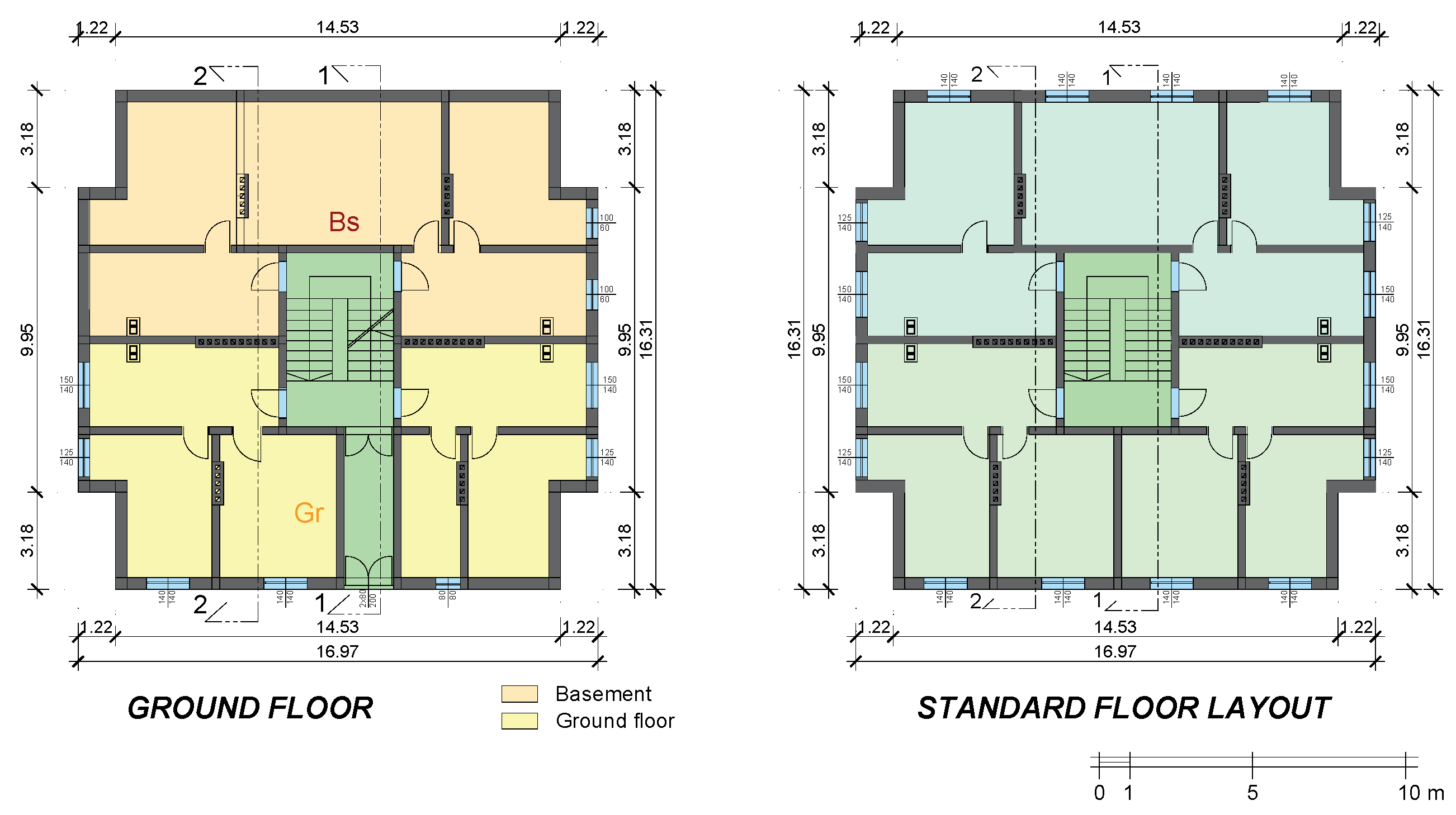
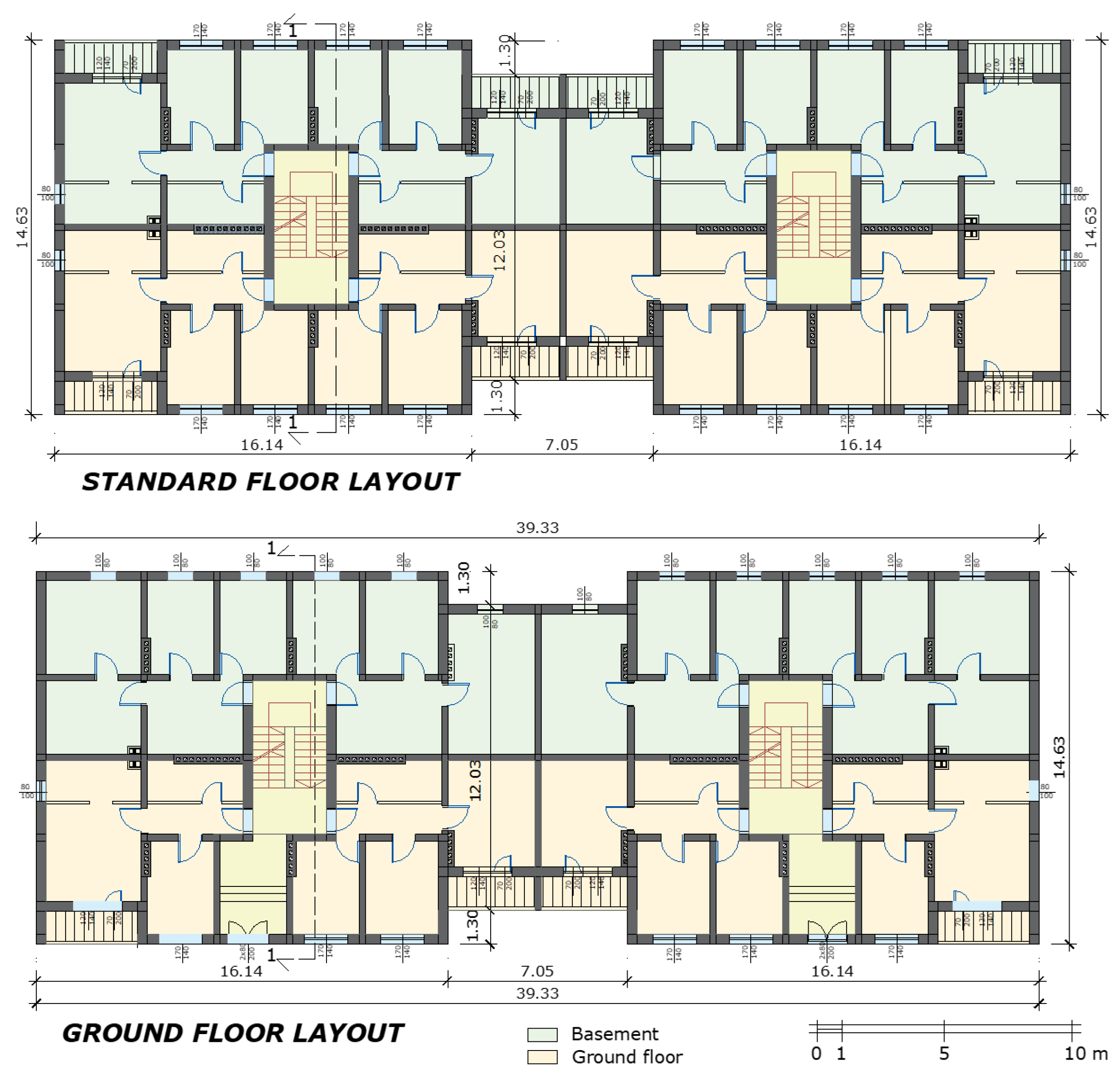
The first type, referred to as Type I (Figure 2), is nearly square in shape at the base, with dimensions of 16.97 m in the x-direction and 16.31 m in the y-direction. The second type, Type II, has a rectangular base with dominant load-bearing walls along the x-direction in the length of 39.33 m and 14.63 m in the y-direction (Figure 3). Both types have a total of five above-ground floors and a basement under one part of the building.
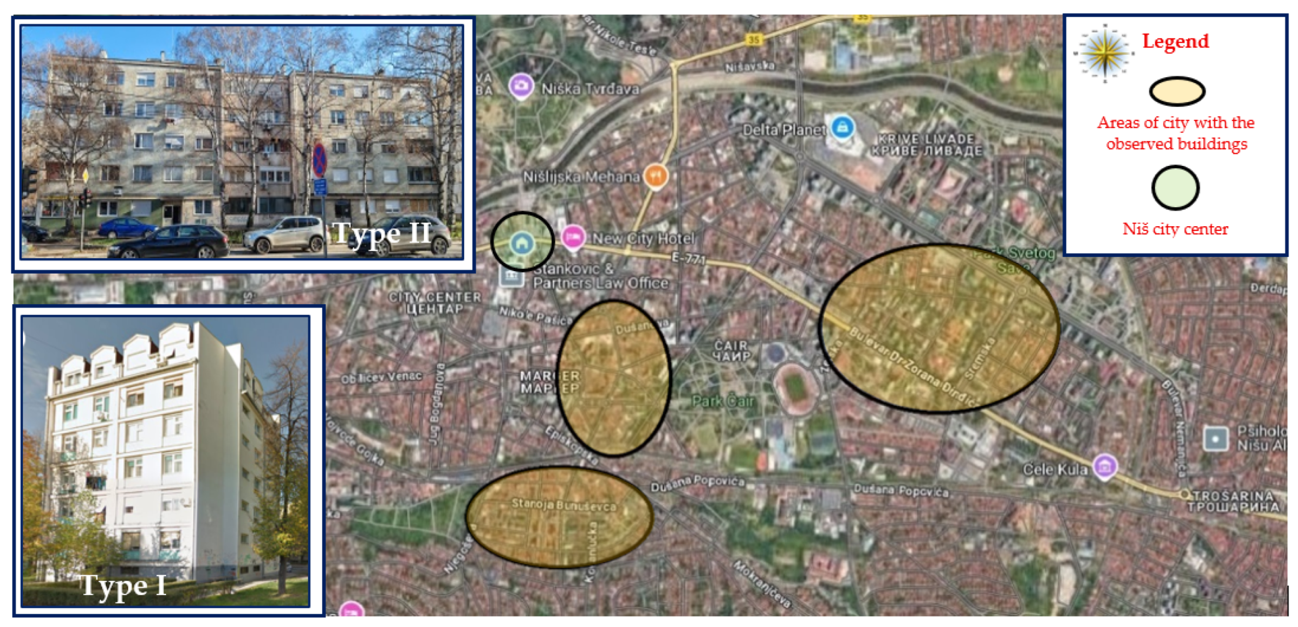
Figure 4 illustrates the areas of the city with the highest number of buildings constructed during the observed period. Out of a total of 100 identified structures, 40% are square-based buildings (Type I), while 60% are elongated rectangular geometry buildings (Type II).
These buildings were selected for the analysis because they represent the predominant urban typologies (square plan, Type I, and elongated rectangular, Type II), are characteristic of structures vulnerable to both seismic- and energy-related deficiencies, and provide sufficient structural and energy data, allowing the assessment of interventions with the greatest potential impact on building performance and the urban environment. If we look at the buildings from a structural point of view, we can conclude that most of these buildings have walls without tie-columns. The building envelope comprises a system of interconnected solid brick walls that extend continuously from the foundation to the roof. The external and internal load-bearing walls are made of solid brick, with the dimensions 250 × 120 × 65 mm, with a thickness varying between 38 cm and 25 cm throughout the building. The examination of the class of building bricks, built into the walls of buildings from the observed location, was carried out by the Institute of Civil Engineering and Architecture of the Faculty of Civil Engineering and Architecture in Niš. On that occasion, it was determined that the average compressive strength of the brick was 11.43 N/mm2, and the individual minimum compressive strength was 10.17 N/mm2. It was not possible to test the installed mortars, so, based on numerous previous studies, the compressive strength of the lime mortar in upper stories was adopted as fm = 1.0 N/mm2 (M1 MPa), and for the cement–lime mortar in the basement and ground floor, the value fm = 2.5 N/mm2 (M2.5 MPa) was taken. According to experimental research on similar structures, the concrete compressive strength of 25 MPa was determined, which approximately corresponds to class C20/25 according to Eurocode 2 [28].
Partition walls are also solid brick walls, measuring 7 and 12 cm in thickness. The walls are connected by lintels, parapets, and beams whose composition and quality are not fully known. All external walls are plastered on both sides. The ceiling is a reinforced concrete slab with a system of reinforced concrete beams. Each building had a centrally placed staircase, but no elevators were provided. A large number of existing buildings have so far had specific interventions, which consisted of the addition of one to three floors built on top of the existing structure. In the observed buildings, the average area ranges from 260 to 560 m2, and in some buildings, it is even larger.
Suppose we begin with the fundamental analysis of the representation of the area of structural walls and the number of floors of the building, as outlined in EN 1998-1 [16]. In that case, it can be concluded that, despite the significant share of load-bearing walls (Table 4), buildings with ordinary masonry walls of four stories or more are not permitted in seismic areas with a ground acceleration ag = 0.1 g (Table 3).
For an adequate seismic performance, a building must have a sufficient percentage of pA, min in each horizontal direction on each floor. The prescribed values for n and pA, min are found in the National Annex of Eurocode 8 [22]. According to the seismic hazard map of the Republic Seismological Institute of Serbia [29], a horizontal ground acceleration of 0.1 g corresponds to the Niš location, and the “safe” values of WI/n range from a minimum of 1.25% for severe damage to 1.67% for moderate damage. It should be noted that these values refer to URM (OM) buildings and buildings up to three floors above ground, while higher floors are not allowed in this case.

4. Combined Building Retrofitting Techniques

In the context of combined seismic and energy renovation, it is crucial to consider their compatibility from the outset, particularly in terms of the potential spatial overlap, the scope of application, the level of invasiveness, and the desired level of performance. The choice of the most optimal solutions must be based on the acquired knowledge and the conclusions reached about the behavior of the structure within the framework of previously conducted analyses [30]. Bearing in mind the specificity and complexity of the works, the cost of materials, and the application of specialized technologies, it is necessary to consider the problem from an economic perspective as well. The aim is to design and analyze single-stage interventions that reduce the economic costs while maintaining acceptable performance targets. Integrated seismic and energy retrofitting creates synergies that reduce costs and improve seismic performance, whereas applying only thermal or only seismic measures is insufficient and can lead to both structural vulnerability and wasted resources.
In the scientific literature, various types of integrated seismic and energy solutions for rehabilitation have been proposed, which, as stated in [31], can be grouped according to the method, location, and scope of implementation. Based on previous theoretical and experimental research and experiences from practical applications, the two methods that were most often applied were selected and presented, namely the reinforcement of horizontal joints of masonry walls and the application of reinforced cement coatings. The chosen methods yielded several positive results and reactions during the long-term application period and were well integrated into the existing masonry system. The preparation of the walls for the execution of these interventions, as well as the strengthening itself, involves a series of activities that are the same or very similar in both methods. The observed methods imply interventions on the existing envelope, while the invasiveness depends on the operational strategy. Depending on whether the reinforcement will be applied only from the outside of the existing walls, this will reduce the need to relocate residents, thereby improving the cost-effectiveness of the method.

4.1. Seismic Strengthening

4.1.1. Reinforcement of Horizontal Joints of Masonry Walls

The procedure begins with the removal of the existing plaster from the joints to a depth of one-third of the wall’s width (Figure 5). Before removing the plaster from the joints, the wall must be stabilized and secured. After cleaning and washing the joints, a new mortar, extension, or cement is applied.
The reinforcement of masonry walls in joints is carried out with horizontal reinforcement, whereby the amount of reinforcement must be at least 2 Ø 6 mm for every 20 cm of wall height (Figure 6). This method is used to connect damaged parts of the wall, increase the bearing capacity, and additionally secure the masonry structures. Due to the good adhesion of the ribbed reinforcing bars and the mortar, whereby the reinforcement takes over the tensile stresses, the load-bearing capacity of the wall during shear increases.
The reinforcing bars are placed in the horizontal joints after applying the first layer of plaster, which is up to 2 cm thick. Care is taken to leave enough space (minimum 1.5 cm) for using the second layer of plaster. After the completion of this phase, the seismic strengthening of the masonry structure, it is possible to continue with the next one, which involves installing the thermal envelope and replacing the existing joinery.

4.1.2. Application of Reinforced Cement Coatings

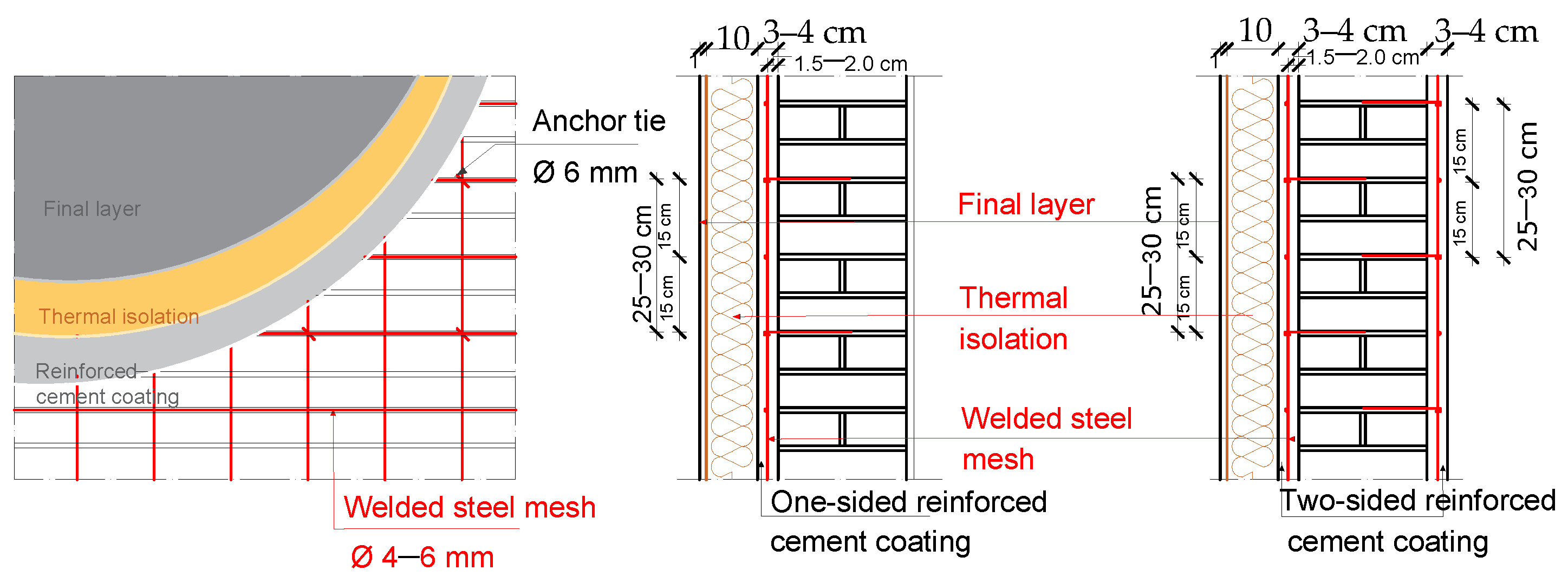
This method envisages the application of a combination of reinforcing mesh and cement coatings on one or both sides of the wall [17]. For construction, the wall should first be prepared, the mortar joints should be cleaned to a depth of 10–15 mm, and then the cracks, if any, should be filled with the appropriate mixture, and the wall should be wetted with water and sprayed with cement milk. The first layer of 1.5–2.0 cm thick cement mixture can then be applied to the wall prepared in this way. A reinforcing mesh made of rods ∅ 4, 5, 6, 8, and 10 mm at 15 cm or 20 cm in both directions is placed over it, and it must be anchored in the wall (Figure 7). The holes in which the anchors are placed should have a minimum diameter of 5 cm, so that a layer of cement or epoxy mixture protects the anchors well. By applying the last final layer of cement mixture, the total thickness of the applied layers should not exceed 4 cm. These reinforcements are carried out continuously from the foundation to the intended floor. Reinforcement mesh must be anchored in vertical and horizontal beams.
Figure 6 and Figure 7 illustrate the practical implementation of the seismic wall strengthening system, showing the low thickness of the complete system and its compatibility with the existing masonry base, which are the key advantages of these strengthening measures.

4.2. Energy Upgrading of Buildings

Previous measurements, recordings with appropriate equipment, and specific calculations have shown that heat losses through opaque walls, floor slabs, the roof, and other structural elements constitute a significant portion of a building’s total energy losses, highlighting the necessity of adequately insulated structures. The proposed solution, as seen in Table 5, involves interventions on the following structures:
  • External walls—adding thermal insulation of mineral stone wool with a thickness of 8 cm on the outside of the façade wall with a thin final layer of plaster. The thermal insulation layer is fixed to the wall with plastic dowels, which should be long enough to pass through the thermal insulation and the cement mortar layer, and enter the brick wall. For the thermal insulation to be well fixed to the wall, it is necessary to use 6–8 dowels per m2. At the corners, a larger number of 8–12 pieces per m2 is required.
  • Walls to the unheated staircase—the addition of thermal insulation material over the structurally reinforced wall.
  • Roofing—the application of thermal insulation in panels made of 16 cm extruded expanded polystyrene (XPS), which is placed over the existing sealing structure, with appropriate layers of vapor-permeable and waterproof membrane below and a waterproofing system over the thermal insulation material.
  • Floor construction above an unheated space—it is planned to add 6 cm of thermal insulation material from the bottom side of the plate, with a thin final layer of plaster.
  • Glazing—the replacement of existing old wooden single-glazed windows with secondary windows. The heat transmission coefficient of old wooden windows is 3.0 W/m2 K, while with double thermally insulated glass it is 1.30 W/m2 K. A PVC double-glazed window comprising two panes of 4 mm float glass, one with a 1% normal emissivity coating, and a 15 mm argon-filled cavity should be used.
  • Doors—the solution also includes replacing doors facing unheated spaces with thermally insulated doors.
According to the Rulebook on the Energy Efficiency of Buildings in Serbia [32], a building is considered energy efficient when minimum comfort requirements (air, thermal, light, and acoustics) are met, and the final energy consumption does not exceed the prescribed maximum values depending on the type and purpose of the building. For existing multi-family residential buildings, the maximum annual energy consumption for heating is set at 70 kWh/m2.
In addition, the annex “Thermal Protection and Water Vapor Diffusion” defines the threshold values of thermal envelope parameters, including the heat transfer coefficient (U), water vapor diffusion, the occurrence of surface condensation, and the thermal protection properties of external elements during the summer period. The regulation specifically prescribes the maximum permissible heat transfer coefficients for existing buildings, as presented in Table 5.
It is also important to emphasize another requirement from the Rulebook on the Conditions, Content, and Procedure for Issuing Certificates on the Energy Performance of Buildings [32]: existing buildings undergoing reconstruction, extension, renovation, adaptation, rehabilitation, or energy retrofitting must achieve an improvement of at least one energy class.

5. Seismic Analysis and Retrofitting of Existing Masonry Buildings

The two most common types of unreinforced masonry buildings in the city of Niš, Republic of Serbia (Figure 2 and Figure 3), were analyzed in terms of seismic demands.
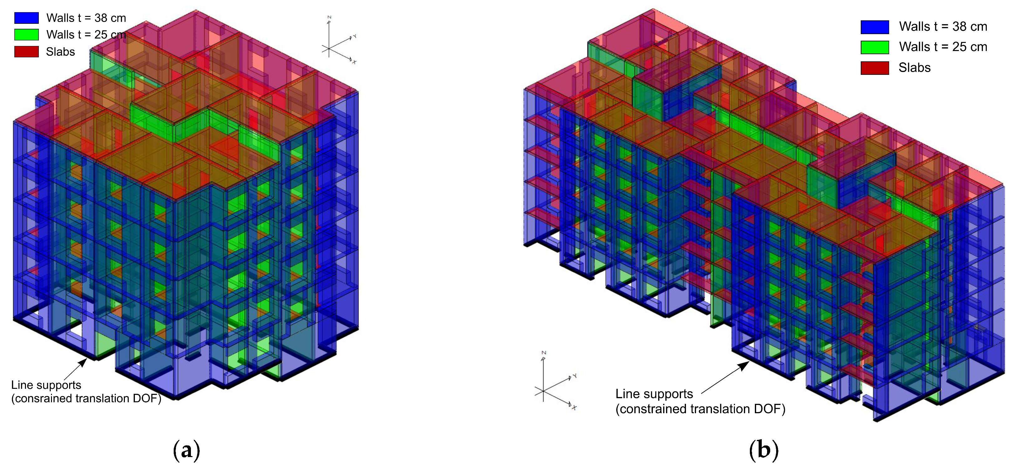
The analyses were performed using the finite element method (FEM) and commercial software “Radimpex Tower 8.5”. The masonry walls and slabs were modeled with shell elements (Figure 8). The foundation of the structure was not the subject of this case study analysis, where it is assumed that the building is fixed at the foundation level, which is a common assumption in the seismic analysis of buildings. Therefore, appropriate line supports on the walls at the foundation level were defined in the numerical model, constraining the translation degrees of freedom (Figure 8).
Considering the experimentally obtained normalized mean compressive strength of the clay masonry units of group 1 fb = 10 MPa, and the estimated value of the compressive strength of the mortar in the basement and on the ground floor fm = 2.50 MPa, and on other floors fm = 1.00 MPa, the characteristic compressive strengths of the masonry are [24,33] as follows:
fk = K fb0.70 fm0.30 = 0.55·100.70 · 2.500.30 = 3.629 MPa (basement and ground floor),
fk = K fb0.70 fm0.30 = 0.55 · 100.70 · 1.000.30 = 2.757 MPa (other floors).
The short-term secant modulus of elasticity of masonry walls is [24,33]
E = KE fk = 1000 · 3.629 = 3629 MPa (basement and ground floor),
E = KE fk = 1000 · 2.757 = 2757 MPa (other floors).
The masonry walls and reinforced concrete slabs have been modeled with linear elastic material models. For the masonry walls’ moduli of elasticity, Equations (3) and (4) were applied, while the standard modulus of elasticity of concrete class C20/25 of 30 GPa was used [28].
The dead load comprises the self-weight of the structural elements and an additional load of 2.50 kN/m2 intensity, whereas the live load for category A (residential activities) is 2.00 kN/m2 [34,35]. The loads are uniformly distributed over all floor slabs. The snow load was not analyzed, considering that the factor for the quasi-permanent value of a snow load is equal to zero; therefore, snow load is not included in the seismic masses. The seismic effects were calculated using a modal response spectrum linear–elastic analysis and q-factor approach [15,16,22,36], where twelve fundamental periods were considered, providing effective modal masses larger than 90%. The seismic forces were calculated for the following input parameters: importance class II γI = 1.0, behavior factor for unreinforced masonry structure q = 1.50, ground type C and elastic response spectrum type 1 S = 1.15, TB = 0.20 s, TC = 0.60 s, TD = 2.00 s, and reference peak ground acceleration on type A ground at the building location agR = 0.10 g. Class II is recommended for an ordinary multi-family housing building according to the standard [16], while the adopted behavior factor is in accordance with the provisions of the national annex for the URM [22]. The identification of the ground type was performed based on the available basic geological maps and results of geotechnical investigations at locations near the analyzed building area. The reference peak ground acceleration was defined based on the seismic hazard map of the Republic of Serbia for a return period of 475 years [29]. To account for the effects of cracking, the analyses were conducted with one half of the initial stiffness of the masonry walls, while the slabs are treated as rigid diaphragms.
The dynamic characteristics (fundamental periods), seismic shear forces, inter-story drift ratios, seismic walls shear demands, and strength capacities of the analyzed building types were analyzed and presented in the following sections.

5.1. Dynamic Characteristics, Seismic Shear Forces, and Inter-Story Drift Ratios

The modal and seismic analyses were conducted considering seismic masses, which include the full intensity of the dead load and the quasi-permanent value of the live load. According to the fundamental periods, it is observed that the structures are relatively stiff (Table 6).
The distribution of the seismic story shear forces for the analyzed buildings was also examined (Figure 9). It can be concluded that the base shear forces in the x and y directions are approximately the same in the case of building Type I. In contrast, for building Type II, the base shear force in the x direction is approximately 7% larger than the base shear force in the y direction.
Another essential factor of the seismic response of the structure is the inter-story drift ratio. The maximal inter-story drift ratio is at the second floor in the case of building Type I and at the first floor in the case of building Type II (Figure 10). It is essential to mention that the inter-story drift ratios are less than the limitation value, considering that the masonry structures are generally stiff.

5.2. Seismic Strength Safety Verification

The safety verification should be conducted by comparing the seismic demands due to the reduced seismic action according to the q-factor approach with the seismic capacities of load-bearing structural elements (shear masonry walls). The seismic capacities of walls at the ground floor were defined based on the experimentally obtained normalized mean compressive strength of the clay masonry units and the estimated value of the compressive strength of mortar, appropriately divided by the confidential factor. Considering that the knowledge level for the analyzed buildings is limited, the adopted confidential factor is CFKL1 = 1.35 [15,36]. Accordingly, the shear capacity of unconfined masonry wall VRd,mw could be obtained as [24]
V Rd , mw = f vd   t   l c = f vk γ m CF KL 1   t   l c = min f vko + 0.4 σ d ; 0.065 f b γ m CF KL 1   t   l c ,
where fvko = 0.20 N/mm2 is the characteristic initial shear strength of masonry (clay masonry units and general-purpose mortar class M2.5) [24]; σd is the design compressive stress; t and lc are the thickness and compressed length of the wall, respectively; and γm = 1.50 is the partial safety factor for masonry material [22].
For reinforced retrofitted masonry walls, the shear capacity of the unconfined masonry wall VRd,mw is increased for the design capacity of horizontal reinforcement VRd,s [16,22,24] according to
V Rd , r = V Rd , mw + V Rd , s = min f vko + 0.4 σ d ; 0.065 f b γ m CF KL 1   t   l c + 0.9   A sw   f yk γ s ,
where Asw is the total area of the horizontal shear reinforcement; fyk is the characteristic strength of reinforcing steel (500 MPa for the analyzed cases); and γs = 1.0 is the partial safety factor for reinforcing steel material [16,22,24].
Another condition that should be satisfied in the case of reinforced masonry walls is [24]
V Rd , mw + V Rd , s t   l 2.0   N mm 2
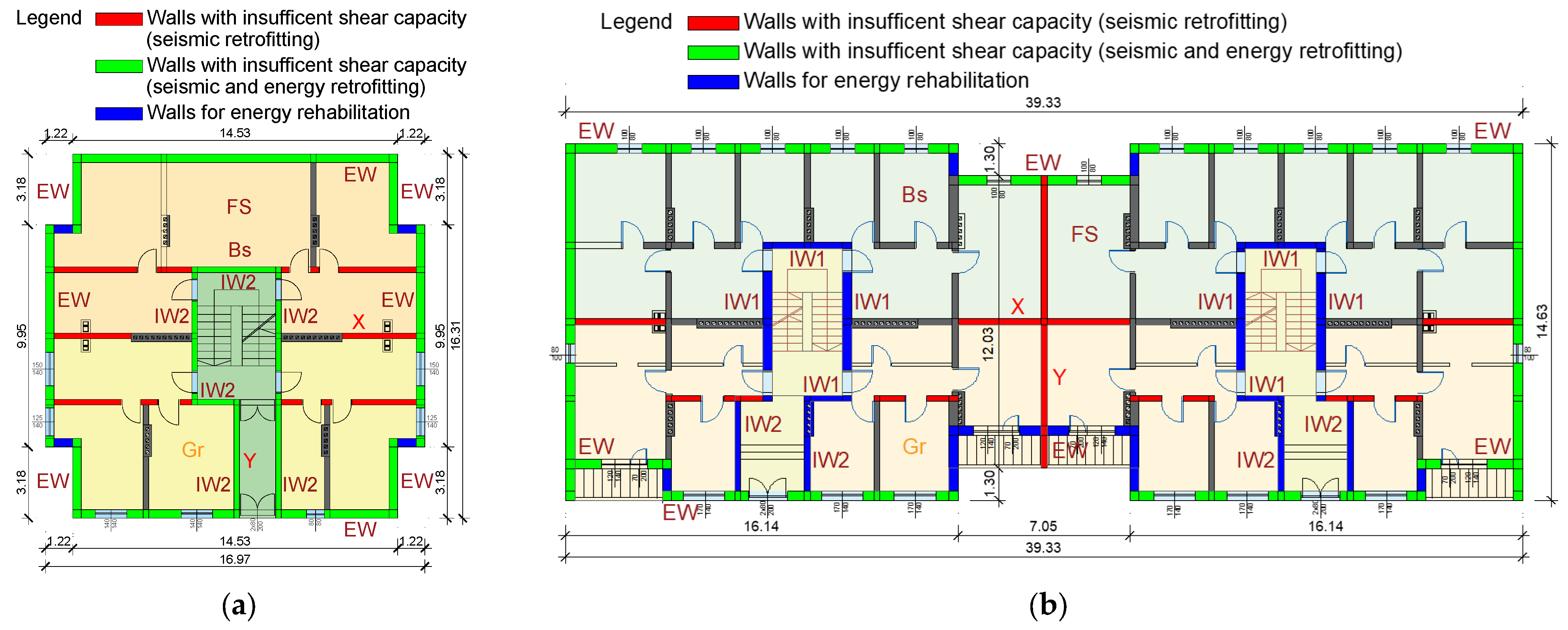
The overall seismic strength safety verification was conducted for all masonry walls, and the walls with an insufficient shear capacity are marked in Figure 11. Details of the analysis for one characteristic wall in each direction (Figure 11) are presented in Table 7 for the sake of brevity. The comparative analysis encompasses seismic shear demand VEd, shear capacity VRd (calculated using Equations (5) and (6)), and the shear demand/capacity ratio for analyzed cases of an existing unconfined masonry structure (OM) and a retrofitted reinforced masonry structure (RM). In the case of the reinforced masonry wall retrofitting technique, the reinforcing mesh is placed in the plaster layer on the external side of the façade walls and on both sides of the internal walls, where the applied welded fabric reinforcement mesh is Ø 4/20 [37].
Considering the results of the conducted analyses, one may conclude that the shear demand/capacity ratio (VEd/VRd,r) for the retrofitted walls (RM) is less than 1, meaning that the standard requirement for seismic demand not exceeding capacity is fulfilled. Therefore, it can be concluded that the retrofitting method involving the application of reinforcement mesh in the plaster layer placed on one or both wall sides could be adequate for upgrading the seismic capacity of existing load-bearing masonry residential buildings.

6. Analysis of the State of Energy Efficiency Improvement

The effective design of thermal bridges, the appropriate thickness of thermal insulation on partitions, appropriate joinery, and the proper sealing of joints between openings and joinery result in energy-efficient buildings. The implementation of these measures achieves a healthy climate in the premises for people to stay, the protection of structures from harmful influences (such as moisture and temperature), lower energy consumption for heating and cooling, and the preservation of the natural environment. Energy calculations at the building level were performed according to the EN ISO 13790:2008 standard [38], utilizing URSA GF 2 software, which complies with Serbian standards in the field of energy efficiency. The software is designed for producing energy passports in accordance with the Regulation on the Conditions, Content, and Method of Issuing Certificates on the Energy Properties of Buildings, as well as the accompanying standards SRPS EN 52003; SRPS U.J5.520; SRPS U.J5.530 [32,39,40,41].
Table 8 shows a comparative analysis of the situation regarding the technical thermal characteristics of the structures that make up the thermal envelope of the building from the case study. Based on the analysis of the existing situation, it is concluded that the constructions separating the heated from the unheated spaces have U-values two to nine times higher than the maximum prescribed values (Table 5). The consequences of this situation are a low internal surface temperature, significant heat losses, poor air quality in the premises, and other accompanying indicators. Also, in some of the mentioned structures, condensation occurs in the winter period, which again leads to possible harmful effects and damage.
This data collectively demonstrates how specific renovation measures, such as improvements to external walls, flat roofs, windows, and floor constructions (Figure 11), contribute to enhanced energy efficiency by reducing the heat loss and overall energy demand for heating. Table 8 quantifies the savings in specific annual energy required for heating compared with the existing state: 77% (151.67 kWh/m2) after improvement for building Type I and 57.6% (81.84 kWh/m2) after improvement for building Type II. It is concluded that the implementation of the external thermal insulating composite system (ETICS) and the replacement of all windows and doors lead to a considerable improvement in the thermal technical characteristics of the observed buildings and their energy efficiency upgrade, as stated in [42]. It is also important to emphasize that energy regulations in Serbia stipulate that newly constructed buildings must belong to at least energy class C. Therefore, it can be concluded that interventions on the entire thermal envelope of a building can achieve an energy performance equivalent to new construction standards [43].

7. Conclusions

The impaired security and stability of buildings, as well as the impaired quality of housing, lead to numerous new problems of a technical, urban, social, economic, and legal nature, which necessitate the initiation of a process of the significant renovation and improvement of residential buildings and the spaces in which they exist. Current efforts focus on developing more accurate and comprehensive methods that account for seismicity, energy efficiency, climate change, and material degradation, while remaining practical for engineering application. Integrating these solutions into existing simulation software could overcome key barriers to widespread adoption. This study provides an overview of integrated seismic and energy retrofitting techniques in Serbia and the wider Balkan region, highlighting feasible approaches and areas for further improvement. The main limitations of the program include the required ownership documentation, permit acquisition procedures, the costs of strengthening works for residents, and the need for temporary relocation. Decisions are made by a majority of owners, while legal procedures for dissenting owners are complex. Strengthening interventions may also reduce interior apartment space or require partial reconfiguration.
This paper presents and discusses an integrated structural and energy retrofitting system specifically designed for masonry buildings. The proposed method combines an effective layer of reinforced cement coating with an external insulation layer, which are both applied exclusively to the exterior masonry surfaces. The results demonstrate a significant enhancement of seismic performance, with delayed collapse mechanisms, while the simultaneous renovation of windows and external insulation improves the building’s energy efficiency by a factor of three to four compared with individual interventions. Comparable improvements were observed in seismic performance, confirming the effectiveness of the integrated retrofitting approach. Applied energy retrofitting measures also solved the problem of condensation in structures that separate heated from unheated spaces. The obtained results show that even with the minimum required thickness of the thermal insulation material, which complies with the maximum permitted values of the heat transmittance prescribed by the regulations, the improvement is substantial. Overall, the findings confirm that multi-objective seismic–energy retrofitting can generate strong synergies, lowering economic costs through reduced installation time, materials, and labor, and enabling an improvement of seismic performance.
The findings indicate that the implementation of isolated measures entails considerable limitations and potential adverse consequences. In particular, the thermal retrofitting of existing masonry buildings without concurrent structural strengthening may not only result in significant seismic vulnerability but also in the inefficient use of financial resources. This highlights that seismic strengthening alone, without concurrent thermal insulation and energy upgrading, is insufficient to address the problems caused by inadequate thermal protection, emphasizing the need for an integrated retrofitting approach.
The long-term benefits of this approach include enhanced seismic resistance and energy efficiency, resulting in lower heating and cooling costs and an extended service life of the building.

Author Contributions

Conceptualization, J.S. and A.Z.; methodology, J.S.; software, J.S., A.Z., and M.N.; validation, A.Z., M.N., and D.R.; formal analysis, J.S., A.Z., and M.N.; investigation, A.Z. and M.N.; resources, J.S. and M.N.; data curation, J.S., A.Z., and D.R.; writing—original draft preparation, J.S. and A.Z.; writing—review and editing, A.Z. and D.R.; visualization, D.Đ.M.; supervision, J.S. and A.Z.; project administration, D.R. and D.Đ.M.; funding acquisition, J.S., A.Z., and D.R. All authors have read and agreed to the published version of the manuscript.

Funding

This research was supported by the Ministry of Science, Technological Development, and Innovation of the Republic of Serbia, under the Agreement on Financing the Scientific Research Work of Teaching Staff at the Faculty of Civil Engineering and Architecture, University of Niš—registration number: 451-03-137/2025-03/200095 dated 4 February 2025.

Institutional Review Board Statement

Not applicable.

Informed Consent Statement

All original contributions presented in this study are contained within the article. For further information, please contact the corresponding author.

Data Availability Statement

The original contributions presented in this study are included in the article. Further inquiries can be directed to the corresponding author.

Conflicts of Interest

The authors declare no conflicts of interest.

References

  1. Popović, M.J.; Ignjatović, D.; Radivojević, A.; Rajčić, A.; Đukanović, L.j.; Ćuković Ignjatović, N.; Nedić, M. National Typology of Residential Buildings in Serbia; Faculty of Architecture, University of Belgrade and GIZ—Deutsche Gesellschaft fur Internationale Zusammenarbeit: Belgrade, Serbia, 2013; p. 379. ISBN 978-86-7924-102-3. [Google Scholar]
  2. Pohoryles, D.; Bournas, D.; Da Porto, F.; Santarsiero, G.; Triantafillou, T.; Oliveira, D.; Jelle, B.P. Technologies for the Combined Seismic and Energy Upgrading of Existing Buildings; EUR 31012, EN.; Publications Office of the European Union: Luxembourg, 2022; ISBN 978-92-76-49257-3. [Google Scholar] [CrossRef]
  3. Izol, R.; Işık, E.; Avcil, F.; Arslan, M.H.; Arkan, E.; Büyüksaraç, A. Seismic performance of masonry structures after 06 February 2023 earthquakes; site survey and FE modelling approach. Soil Dyn. Earthq. Eng. 2024, 186, 108904. [Google Scholar] [CrossRef]
  4. Regulations of Energy Efficiency of Buildings; Official Gazette of the Republic of Serbia. No. 61/2011; Official Gazette of the Republic of Serbia: Beograd, Serbia, 2011. (In Serbian)
  5. Penazzato, L.; Illampas, R.; Oliveira, D.V. The Challenge of Integrating Seismic and Energy Retrofitting of Buildings: An Opportunity for Sustainable Materials? Sustainability 2024, 16, 3465. [Google Scholar] [CrossRef]
  6. Feroldi, F.; Marini, A.; Belleri, A.; Passoni, C.; Riva, P.; Preti, M.; Giuriani, E.; Plizzari, G.A. Miglioramento e adeguamento sismico di edifice contemporanei mediante approccio integrato energetico, architettonico e strutturale con soluzioni a doppio involucro a minimo impatto ambientale. Progett. Sismica 2014, 5, 31–47. [Google Scholar] [CrossRef]
  7. Requena-Garcia-Cruz, M.-V.; Díaz-Borrego, J.; Romero-Sánchez, E.; Morales-Esteban, A.; Campano, M.-A. Assessment of Integrated Solutions for the Combined Energy Efficiency Improvement and Seismic Strengthening of Existing URM Buildings. Buildings 2022, 12, 1276. [Google Scholar] [CrossRef]
  8. Facconi, L.; Lucchini, S.S.; Minelli, F.; Grassi, B.; Pilotelli, M.; Plizzari, G.A. Innovative Method for Seismic and Energy Retrofitting of Masonry Buildings. Sustainability 2021, 13, 6350. [Google Scholar] [CrossRef]
  9. Kallioras, S.; Bournas, D.; Koutas, L.; Molina, F.J. Integrated seismic and energy retrofitting of masonry-infilled RC buildings with textile-reinforced mortar and thermal insulation: Full-scale tests on a five-story prototype. J. Build. Eng. 2024, 98, 111006. [Google Scholar] [CrossRef]
  10. Milovanović, B.; Bagarić, M.; Gaši, M.; Stepinac, M. Energy renovation of the multi-residential historic building after the Zagreb earthquake—Case study. Case Stud. Therm. Eng. 2022, 38, 102300. [Google Scholar] [CrossRef]
  11. Ademovic, N.; Formisano, A.; Penazzato, L.; Oliveira, D.V. Seismic and energy integrated retrofit of buildings: A critical review. Front. Built Environ. 2022, 8, 963337. [Google Scholar] [CrossRef]
  12. Besen, P.; Boarin, P. Integrated energy retrofit with seismic upgrades to future-proof built heritage: Case studies of unreinforced masonry buildings in Aotearoa New Zealand. Build. Environ. 2023, 241, 110512. [Google Scholar] [CrossRef]
  13. Caruso, M.; Buttazzoni, M.; Passoni, C.; Labò, S.; Marini, A.; Pinho, R. An updated multi-criteria decision-making method for the sustainable renovation of buildings including environmental, economic and social life-cycle metrics. J. Build. Eng. 2024, 98, 110967. [Google Scholar] [CrossRef]
  14. Günay, H.; Torunbalcı, N. Retrofit of Masonry Structures with Seismic Control Methods and Architectural Design Requirements. J. Archit. Eng. 2023, 29, 1594. [Google Scholar] [CrossRef]
  15. EN1998-3:2005; Eurocode 8-Design of Structures for Earthquake Resistance-Part 3: Assessment and Retrofitting of Buildings. European Committee for Standardization: Bruxelles, Belgium, 2005.
  16. EN1998-1:2005; Eurocode 8-Design of Structures for Earthquake Resistance-Part 1: General Rules, Seismic Actions and Rules for Buildings. European Committee for Standardization: Bruxelles, Belgium, 2005.
  17. Tomaževič, M. Earthquake—Resistant Design of Masonry Buildings, Series on Innovation in Structures and Construction—Vol. 1; Imperial College Press: London, UK, 1999. [Google Scholar]
  18. Popović, M.J.; Dusan, I.; Radivojević, A.; Rajcic, A.; Đukanović, L.; Ignjatovic, N.C.; Nedić, M. National Typology of Residential Buildings in Serbia; Faculty of Architecture, University of Belgrade; GIZ-Deutche Gesellschaft fur Internationale Zusammenarbeit: Belgrade, Serbia, 2013. [Google Scholar]
  19. Blagojević, P.; Brzev, S.; Cvetković, E. Seismic Retrofitting of Mid-Rise Unreinforced Masonry Residential Buildings after the 2010 Kraljevo, Serbia Earthquake: A Case Study. Buildings 2023, 13, 597. [Google Scholar] [CrossRef]
  20. PTP-12. Privremeni Tehnički Propisi za Građenje u Seizmičkim Područjima (Provisional Technical Regulations for Construction in Seismic Regions); Official Gazette of SFRY No. 39/64; Yugoslav Institute for Standardization: Belgrade, Serbia, 1964. (In Serbian) [Google Scholar]
  21. PTN-S. Pravilnik o Tehničkim Normativima za Izgradnju Objekata Visokogradnje u Seizmičkim Područjima (Technical Regulations for the Design and Construction of Buildings in Seismic Regions); Official Gazette of SFRY No. 31/81 (Amendments 49/82, 29/83, 21/88,52/90); Yugoslav Institute for Standardization: Belgrade, Serbia, 1981; Available online: https://iisee.kenken.go.jp/worldlist/64_Serbia/64_Serbia_Code.pdf (accessed on 20 July 2025)(In Serbian; Partial English Version).
  22. SRPS EN 1998-1/NA:2018; Evrokod 8—Projektovanje Seizmički Otpornih Konstrukcija—Deo 1: Opšta Pravila, Seizmička Dejstva i Pravila za Zgrade—Nacionalni Prilog, Institut za Standardizaciju Srbije (Eurocode 8-Design of Structures for Earthquake Resistance-Part 1: General Rules, Seismic Actions and Rules for Buildings—National Annex). Institute for Standardization of Serbia: Belgrade, Serbia, 2018. (In Serbian)
  23. PTP-Z. Privremeni Tehnički Propisi za Zidove od Opeke (PTP-7) (Temporary Technical Regulations for Brick Walls); Official Gazette of Federal People Republic of Yugoslavia No. 32/47; Yugoslav Institute for Standardization: Belgrade, Serbia, 1949. (In Serbian) [Google Scholar]
  24. EN1996-1-1:2005; Eurocode 6-Design of Masonry Structures-Part 1-1: General Rules for Reinforced and Unreinforced Masonry Structures. European Committee for Standardization: Bruxelles, Belgium, 2005.
  25. Blagojević, P.; Brzev, S.; Cvetković, R. Simplified Seismic Assessment of Unreinforced Masonry Residential Buildings in the Balkans: The Case of Serbia. Buildings 2021, 11, 392. [Google Scholar] [CrossRef]
  26. PTN-Z. Pravilnik o Tehničkim Normativima za Zidane Zidove (Technical Norms Regulation for Masonry Walls); Official Gazette of SFRY No. 87/91; Yugoslav Institute for Standardization: Belgrade, Serbia, 1991. (In Serbian) [Google Scholar]
  27. Keković, A.; Čemerigić, Z. Moderna Niša 1920–1941. Arhitektura Grada, Društvo Arhitekata Niša, Niš 2006 (Modern Niš 1920–1941. Architecture of the City, Society of Architects of Niš, Niš 2006); Society of Architects of Niš: Niš, Serbia, 2006. (In Serbian) [Google Scholar]
  28. EN1992-1-1:2004; Eurocode 2-Design of Concrete Structures-Part 1-1: General Rules and Rules for Buildings. European Committee for Standardization: Bruxelles, Belgium, 2004.
  29. Republički Seizmološki Zavod. Available online: https://www.seismo.gov.rs/Seizmicnost/SH_2018_Ubrzanje_lat_475_WGS84.pdf (accessed on 22 July 2025).
  30. Petronijević, P.; Momčilović-Petronijević, A.; Stanimirović, M. Condition Assessment and Structural Rehabilitation of the St. Nicholas Church in Crna Trava. Facta Univ. Ser. Archit. Civ. Eng. 2021, 19, 279–293. [Google Scholar] [CrossRef]
  31. Pohoryles, D.A.; Bournas, D.A.; Da Porto, F.; Santarsiero, G.; Triantafillou, G.; Oliveira, D.; Jelle, B.P. Technologies for the Combined Seismic and Energy Upgrading of Existing Buildings, 1st ed.; Publication Office of the European Union, Joint Research Centre: Luxembourg, 2022. [Google Scholar]
  32. Pravilnik o Uslovima, Sadržini i Načinu Izdavanja Sertifikata o Energetskim Svojstvima Zgrada, “Službeni Glasnik RS”, br. 69/2012, 44/2018—Dr. Zakon i 111/2022 (Regulation on the Condition, Content, and Method of Issuing Certificates on the Energy Properties of Buildings, Official Gazette of the Republic of Serbia”, No. 69/2012, 44/2018—Other law and 111/2022); Official Gazette of the Republic of Serbia: Belgrade, Serbia, 2012. (In Serbian)
  33. SRPS EN 1996-1-1/NA:2019; Evrokod 6—Projektovanje Zidanih Konstrukcija—Deo 1-1: Opšta Pravila za Armirane i Nearmirane Zidane Konstrukcije—Nacionalni Prilog, Institut za Standardizaciju Srbije (Eurocode6-Design of Masonry Structures-Part 1-1: General Rules for Reinforced and Unreinforced Masonry Structures—National Annex). Institute for Standardization of Serbia: Belgrade, Serbia, 2019. (In Serbian)
  34. EN1991-1-1:2002; Eurocode1-Actions on Structures-Part 1-1: General Actions-Densities, Self-Weigth, Imposed Loads for Buildings. European Committee for Standardization: Bruxelles, Belgium, 2002.
  35. SRPS EN 1991-1-1/NA:2015; Evrokod1—Dejstva na Konstrukcije—Deo 1-1: Opšta Dejstva—Zapreminske Težine, Sopstvena Težina, Korisna Opterećenja za Zgrade—Nacionalni Prilog, Institut za Standardizaciju Srbije (Eurocode1-Actions on structures-Part 1-1: General Actions-Densities, self-weigth, imposed loads for buildings—National Annex). Institute for Standardization of Serbia: Belgrade, Serbia, 2015. (In Serbian)
  36. SRPS EN 1998-3/NA:2018; Evrokod 8—Projektovanje Seizmički Otpornih Konstrukcija—Deo3: Procena Stanja I Ojačanje Zgrada—Nacionalni Prilog, Institut za Standardizaciju Srbije (Eurocode 8-Design of Structures for Earthquake Resistance-Part 3: Assessment and retrofitting of buildings—National Annex). Institute for Standardization of Serbia: Belgrade, Serbia, 2018. (In Serbian)
  37. EN 10080:2005; Steel for the Reinforcement of Concrete—Weldable Reinforcing Steel—General. European Committee for Standardization: Bruxelles, Belgium, 2005.
  38. EN ISO 13790:2008; Energy Performance of Buildings—Calculation of Energy for Space Heating and Cooling. European Committee for Standardization: Bruxelles, Belgium, 2008.
  39. SRPS EN ISO 52003-1:2017; Energy Performance of Buildings—Indicators, Requirements, Ratings and Certificates—Part 1: General Aspects and Application to the Overall Energy Performance (ISO 52003-1:2017). International Organisation for Standardization (ISO): Geneva, Switzerland, 2017.
  40. SRPSS.U.J5.520; Toplotna Tehnika u Građevinarstvu—Proračun Difuzije Vodene Pare u Zgradama (Heat in Civil Engineering—Calculation of Water Vapour Diffusion in Buildings). ISO: Belgrade, Serbia, 1997. (In Serbian)
  41. SRPS.U.J5.530; Toplotna Tehnika u Građevinarstvu—Proračun Faktora Prigušenja i Proračun Kašnjenja Oscilacija Temperature Kroz Spoljašnje Građevinske Pregrade Zgrada u Letnjem Razdoblju (Heat in Civil Engineering—Calculation of Damping Factor and Lating of Temperature Oscillations in the Summer Period Through the Exterior Building Partitions). ISO: Belgrade, Serbia, 1997. (In Serbian)
  42. Randjelović, D.; Vasov, M.; Ignjatović, M.; Bogdanović, I.P.; Kostić, D. Impact of trombe wall construction on thermal comfort and building energy consumption. Facta Univ. Ser. Archit. Civ. Eng. 2018, 16, 279–292. [Google Scholar] [CrossRef]
  43. Lević, B.; Đukanović, L.; Dimitrijević, B. Possibilities and Scope of Comprehensive Renovation of Multi-family Residential Buildings in Cultural-historic Areas: A Case Study of Protected Building in the Old Part of Belgrade. Facta Univ. Ser. Archit. Civ. Eng. 2025, 23. [Google Scholar]
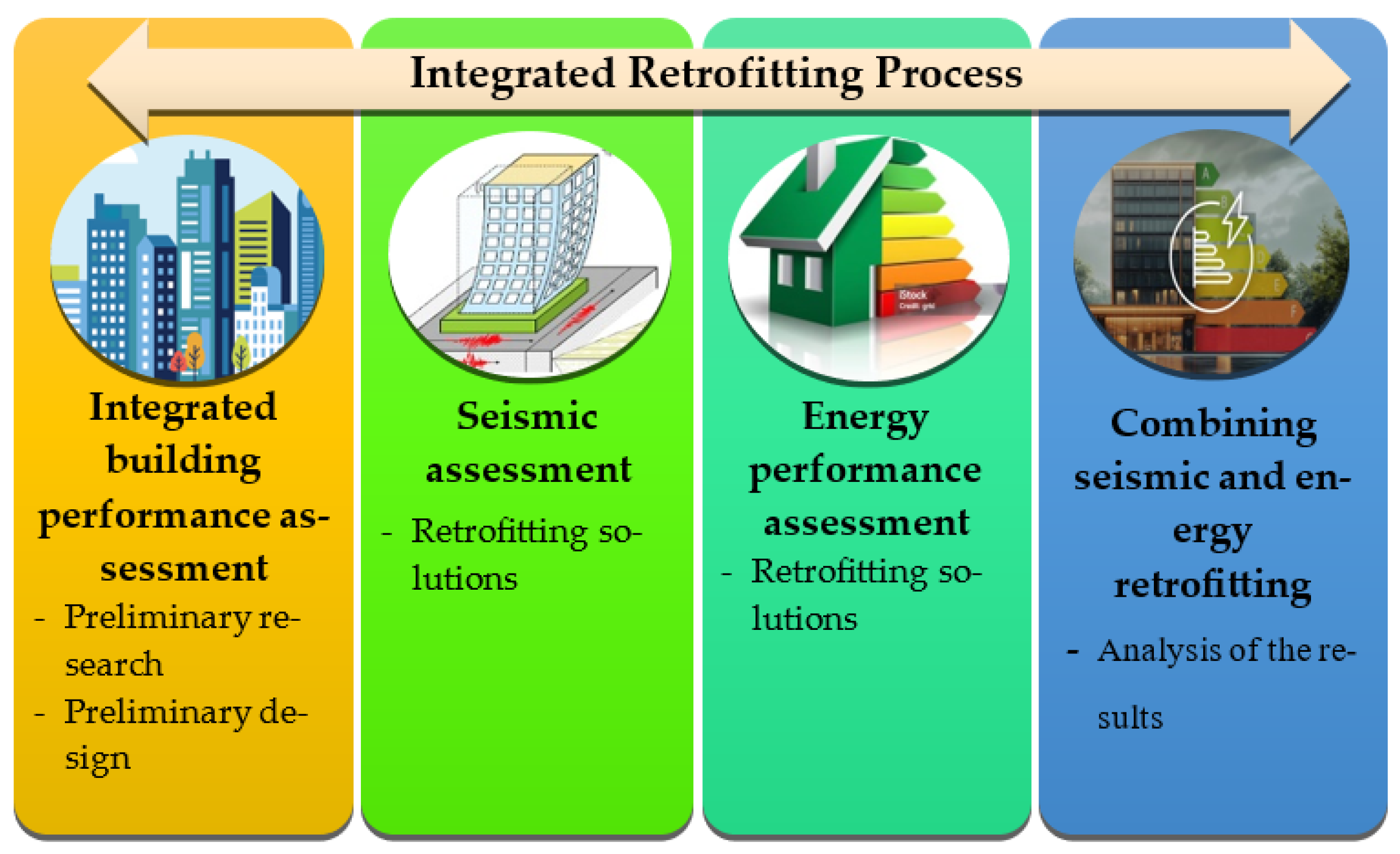
Figure 1. Graphic representation of the integrated retrofitting process.
Buildings 15 03729 g001
Figure 2. Plan of a building with a square layout—Type I.
Buildings 15 03729 g002
Figure 3. Plan of a building with a rectangular layout—Type II.
Buildings 15 03729 g003
Figure 4. Multi-family apartment buildings built in the period from 1945 to 1963 in Niš (city parts marked with elliptical shapes).
Buildings 15 03729 g004
Figure 5. Illustration of seismic strengthening techniques—repointing.
Buildings 15 03729 g005
Figure 6. Reinforcement of horizontal joints with ribbed reinforcement.
Buildings 15 03729 g006
Figure 7. The energy and seismic retrofitting packages include the reinforcement of existing walls and the installation of thermal insulation.
Buildings 15 03729 g007
Figure 8. Numerical model of analyzed buildings: (a) building Type I; (b) building Type II.
Buildings 15 03729 g008
Figure 9. Story shear forces: (a) building Type I—X direction; (b) building Type I—Y direction; (c) building Type II—X direction; (d) building Type II—Y direction.
Buildings 15 03729 g009aBuildings 15 03729 g009b
Figure 10. Inter-story drift ratio: (a) building Type I; (b) building Type II.
Buildings 15 03729 g010
Figure 11. Walls with insufficient shear capacity and energy efficiency: (a) building Type I; (b) building Type II.
Buildings 15 03729 g011
Table 1. Serbian residential building typology applied in the methodology adopted in the IEE Project TABULA [18].
Type of Low-Rise HousingFamily Housing
(Up to 4 Apartments)
Multi-Family Housing
(More Than Four Apartments per Entrance)
Type of High-Rise HousingFurther
Building
Types:
Const. PeriodSingle-Family HousesTerraced HousesMulti-Family HousesApartment BlocksConst. PeriodHigh-Rise
1. <1919Buildings 15 03729 i001Buildings 15 03729 i002Buildings 15 03729 i003Buildings 15 03729 i0041946–1960Buildings 15 03729 i005
2.
1919–1945
Buildings 15 03729 i006Buildings 15 03729 i007Buildings 15 03729 i008Buildings 15 03729 i0091961–1970Buildings 15 03729 i010
3.
1946–1960
Buildings 15 03729 i011Buildings 15 03729 i012Buildings 15 03729 i013Buildings 15 03729 i0141971–1980Buildings 15 03729 i015
4.
1961–1970
Buildings 15 03729 i016Buildings 15 03729 i017Buildings 15 03729 i018Buildings 15 03729 i0191981–1990Buildings 15 03729 i020
5.
1971–1980
Buildings 15 03729 i021Buildings 15 03729 i022Buildings 15 03729 i023Buildings 15 03729 i024Further data is not available
6.
1981–1990
Buildings 15 03729 i025Buildings 15 03729 i026Buildings 15 03729 i027Buildings 15 03729 i028
7.
1991–2011
Buildings 15 03729 i029Buildings 15 03729 i030Buildings 15 03729 i031Buildings 15 03729 i032
Table 2. Comparative presentation of design provisions for URM-type buildings according to different regulations (1949–present).
ProvisionDesign MethodMaterial RequirementsWall Thickness
Allowable StressUltimate Limit StatesMortar StrengthClay Brick Strength
PTP-7 [23]
(period 1949–1964)
////25–38 cm
PTP-12 [20]
(period 1964–1980)
// ***/25–38 cm
PTN-S [21]
(period 1981–2019)
✓ *2.5–5.0 MPa ****10–15 MPaMin. 19 cm
PTN-Z [26]
(period 1991–2019)
✓ *2 MPa ****, 10 MPa *****10 MPaMin. 24 cm/19 cm
(exterior/interior walls)
EN 1998–1 [16]
(period 2020–present)
/✓ **5.0 MPa5.0 MPaMin. 24 cm
(effective thickness)
✓ Applecable * Strength only. ** Strength plus serviceability. *** Cement–lime–sand mortar except for single-story buildings in seismic zones VII and VIII. **** Cement–lime–sand mortar. ***** Cement mortar.
Table 3. Comparison of building height restrictions in different seismic zones for different types of masonry buildings (OM and CM) in regulations from 1964 to the present.
Seismic Intensity
(MSC)
PTP-12 (1964–1980)
OM      CM
Number of Stories (n)
PTN-S (1981–2019)
OM      CM
Number of Stories (n)
EN1998-1 (2020–Present)
OM        CM
Number of Stories (n)
VII56353 **4 **
VIII46242 **3 **
IX35n/a *3n/a *2 **
* n/a—not acceptable, ** limited with minimum area of shear walls for “simple masonry buildings” and with approximation between seismic intensity and acceleration: VII—0.10 g, VIII—0.15 g, IX—0.20 g.
Table 4. Shear walls area with respect to the floor area in the observed buildings.
Percentage of Load-Bearing Shear Walls—X DirectionWall Index Per Floor
WI/n
Percentage of Load-Bearing Shear Walls—Y DirectionWall Index Per Floor
WI/n
Building “Type I”9.7%1.94%8.7%1.74%
Building “Type II”9.3%1.86%10.7%2.14%
Table 5. The thermal transmittance for existing and retrofitted case study buildings.
Existing Building Thermally Retrofitted Building
Name of the StructureImage of the Existing ConstructionStructure
Composition
U
(W/m2 K)
U max
(W/m2 K)
Image of the Improved ConstructionStructure CompositionU
(W/m2 K)
External wall
EW
Buildings 15 03729 i0331. lime mortar 2 cm
2. solid brick 38 cm
3. extension mortar 3 cm
1.2140.40Buildings 15 03729 i0341. lime mortar 2 cm
2. solid brick 38 cm
3.cement mortar 4 cm
4. insulation 8 cm
5. plaster 1 cm
0.321
Wall towards the unheated staircase
IW1
Buildings 15 03729 i0351. lime mortar 2 cm
2. solid brick 38 cm
3. lime mortar 2 cm
1.1070.55Buildings 15 03729 i0361. lime mortar 2 cm
2. solid brick 38 cm
3. cement mortar 4 cm
4. insulation 5 cm
5. lime mortar 2 cm
0.419
Internal wall towards the unheated staircase
IW2
Buildings 15 03729 i0371. lime mortar 2 cm
2. solid brick 25 cm
3. lime mortar 2 cm
1.4290.55Buildings 15 03729 i0381. lime mortar 2 cm
2. solid brick 25 cm
3. cement mortar 4 cm
4. insulation 5 cm
5. lime mortar 2 cm
0.458
Floor structure above the unheated basement
FS
Buildings 15 03729 i0391. parquet on bitumen 2 cm
2. screed 2.5 cm
3. ribbed floor slab 20 cm
4. lime mortar 2 cm
1.2580.40Buildings 15 03729 i0401. parquet on bitumen 2 cm
2. screed 2.5 cm
3. ribbed floor slab 20 cm
4. lime mortar 2 cm
5. insulation 6 cm
6. plaster 1 cm
0.363
Flat roof structure
FRS
Buildings 15 03729 i0411. gravel 7 cm
2. waterproofing insulation 1 cm
3. lean of concrete for a drop ≥3 cm
4. ribbed floor slab 20 cm
5. lime mortar 2 cm
1.9090.20Buildings 15 03729 i0421. gravel 7 cm
2. waterproofing insulation 1 cm
3. insulation 16 cm
4. vapor barrier
5. lean of concrete for a drop ≥3 cm
6. ribbed floor slab 20 cm
7. lime mortar 2 cm
0.191
WindowsBuildings 15 03729 i043Old wooden single-glazed windows with a secondary window3.501.30Buildings 15 03729 i044PVC double-glazed window based on two panes of 4 mm float glass, one with a standard emissivity coating, and a 15 mm argon-filled cavity1.30
Table 6. Fundamental periods of the analyzed cases.
BuildingX DirectionY DirectionTorsional
Type I0.3431 s0.4078 s0.2439 s
Type II0.3813 s0.3292 s0.2858 s
Table 7. Comparative analysis of seismic shear demands and capacities of characteristic masonry walls for cases of existing and retrofitted case study buildings.
BuildingWallGeometrySeismic DemandSeismic Shear Capacity
Unconfined Masonry (OM)Reinforced Masonry
(RM)
t [cm]lc [cm]NEd [kN]MEd [kNm]VEd [kN]VRd,mw [kN]VEd/VRd,mwVRd,s [kN]VRd,r [kN]VEd/VRd,r
Type IX25330819.92335.02268.49243.441.103141.37384.810.698
Y254651032.57752.41454.16318.781.425141.37460.150.987
Type IIX25340614.35111.43340.59205.301.659141.37346.670.982
Y25415853.88246.44303.62271.141.120141.37412.510.736
Table 8. Analysis of the energy required for heating in the state before and after the implementation of specific measures of comprehensive renovation.
Building Type IBuilding Type II
Before ImprovementAfter ImprovementBefore ImprovementAfter Improvement
Area of the heated space Af (m2)786.92786.9219091909
Volume of the heated space Ve (m3)3367.753367.756641.56641.5
Thermal envelope surface Ae (m2)1714.411714.413289.053289.05
Heat losses of the thermal envelope HT (W/K)2470.27793.264597.11490.5
Total heat loss H (W/K)3435.371195.386487.013380.42
Specific annual energy required for heating (kWh/m2)196.0744.4142.0560.21
Energy ClassBuildings 15 03729 i045Buildings 15 03729 i046Buildings 15 03729 i047Buildings 15 03729 i048
Disclaimer/Publisher’s Note: The statements, opinions and data contained in all publications are solely those of the individual author(s) and contributor(s) and not of MDPI and/or the editor(s). MDPI and/or the editor(s) disclaim responsibility for any injury to people or property resulting from any ideas, methods, instructions or products referred to in the content.