Article

Mechanical Response of Composite Wood–Concrete Bonded Facade Under Thermal Loading

Laboratory of Composite Materials for Construction (LMC2), University Claude Lyon 1, 82 bd Niels Bohr, 69622 Villeurbanne, France
*
Author to whom correspondence should be addressed.
Buildings 2025, 15(20), 3664; https://doi.org/10.3390/buildings15203664
Submission received: 8 September 2025 / Revised: 29 September 2025 / Accepted: 2 October 2025 / Published: 11 October 2025
(This article belongs to the Special Issue The Latest Research on Building Materials and Structures)

Abstract

The integration of wood and concrete in building structures is a well-established practice typically realized through mechanical connectors. However, the thermomechanical behavior of wood–concrete composite façades assembled via adhesive bonding remains underexplored. This study introduces a novel concept—the adhesive-bonded wood–concrete façade, termed “Hybrimur”—and evaluates the response of these façade panels under thermal gradients, with a focus on thermal bowing phenomena. Four full-scale façade prototypes (3 m high × 6 m wide), consisting of 7 cm thick concrete and 16 cm thick laminated timber (GL24h), were fabricated and tested both with and without insulation. Two reinforcement types were considered: fiberglass-reinforced concrete and welded mesh reinforcement. The study combines thermal analysis of temperature gradients at the adhesive interface with analytical and numerical methods to investigate thermal expansion effects. The experimental and numerical results revealed thermal strains concentrated at the wood–concrete interface without inducing panel failure. Thermal bowing (out-of-plane deflection) exhibited a nonlinear behavior influenced by the adhesive bond and the anisotropic nature of the wood. These findings highlight the importance of accounting for both interface behavior and wood anisotropy in the design of hybrid façades subjected to thermal loading. A tentative finite element model is proposed that utilizes isotropic wood with properties that limit the accuracy of the results obtained by the model.

1. Introduction

The concept of timber–concrete composite (TCC) structures was first developed in the early 20th century [1]. Initial designs involved connecting concrete slabs to timber beams using nails and steel reinforcements, as illustrated in Yeoh’s study [2]. Originally, TCC technology was predominantly applied in bridge construction, starting in the United States in the 1930s and then spreading to Australia and New Zealand in the 1950s [3] and, eventually, to Europe in the 1990s. After a decline in the 2000s, TCC technology has seen a resurgence [4], particularly in the reinforcement of existing timber floors using shear connectors and thin concrete layers [5,6]. Regarding hybrid façades, Pozza [7] examined the seismic behavior of prefabricated TCC walls and demonstrated their suitability for seismic zones, with experimental results consistent with Eurocode 8 design values. Hybrid timber–concrete structures offer several advantages over traditional reinforced concrete or concrete–steel systems. They enhance structural stiffness and stability, compensate for the limitations of timber in resisting wind loads, and provide the necessary ductility for seismic design. TCC systems can support up to 60% more load compared to conventional timber beams, and their increased stiffness, particularly when ultra-high-performance fiber-reinforced concrete (UHPFRC) is used, helps to reduce long-term deformations [8,9]. Augeard et al. [10] showed that beams made from glued laminated timber (GLT) and UHPFRC exhibit a stiffness increase of approximately 70% to 85% compared to similarly sized glued laminated timber beams. In terms of thermal performance, prefabricated timber frame systems provide effective insulation due to the low thermal conductivity of timber, which is two to four times lower than that of conventional insulating materials [11]. Recent industry trends have included increasing the thickness of exterior walls to improve insulation material installation, with studies such as that of Ge et al. [12] and Sorensen et al. [13] demonstrating significant reductions in heat loss and gain in prefabricated timber wall systems. Comparative studies on materials and construction technologies have revealed significant variations in environmental impact and performance. For instance, Keena et al. [14] showed that prefabricated steel buildings offer substantial savings in embodied energy and mass. Conversely, Frênette et al. [15] indicated that traditional materials such as brick and extruded polystyrene, as well as reinforced concrete structures, have a higher environmental impact compared to timber products. Pérez-García et al. [16] highlighted that multi-layer structural panels (MSPs) incorporating timber reduce material and energy requirements, leading to cost savings and lower CO2 emissions. This is consistent with the findings of J.C Martins et al. [17], who emphasized the importance of connection stiffness for optimizing the performance of composite systems. Various connection technologies, including discrete, continuous, and adhesive connections, play a crucial role in this optimization. Du et al. [18] studied the shear behavior of cross-laminated timber screws, showing that factors such as concrete strength, and screw diameter significantly influence the shear capacity and stiffness of connections. Clouston et al. [19] and Branco et al. [20] demonstrated that adhesive connections can provide high stiffness. Previous research has explored the use of hybrid beams combining glued laminated timber (GLT), ultra-high-performance fiber-reinforced concrete (UHPC), and fiber-reinforced polymers (FRPs). Ferrier et al. (2010) [21] investigated a hybrid beam concept in which the GLT section was reinforced with UHPC on the upper surface of the compressed zone and FRP on the lower surface of the tensioned zone. The results indicated that this combination significantly enhances structural efficiency compared to traditional GLT beams. Due to the high Young’s modulus of UHPC, hybrid beams benefit from increased bending stiffness, allowing for a reduction in height or an increase in span while maintaining optimal performance. Using concrete reinforced with FRP or steel bars substantially increases the ultimate capacity of the beam, surpassing that of similarly sized GLT beams. FRP bars maintain elastic behavior under high loads without altering bending stiffness, unlike steel bars, which modify stiffness once their yield limit is reached. However, enhancing both compressed and tensioned areas also increases the likelihood of shear failure. Ferrier et al. (2012) [22] emphasized the importance of considering combined shear and transverse tensile stresses for hybrid beams, particularly when the span is less than 17 times the height of the beam, to accurately predict deflection. The equations used for GLT beams are also applicable to hybrid beams. The primary challenge of hybrid systems, however, lies in managing the thermal stresses induced by temperature differentials, which can lead to panel deformation and bending. This issue is well documented but not fully understood within civil and mechanical engineering practices [23,24]. In some cases, these thermal stresses can be as significant as those generated by permanent and live loads, potentially causing concrete cracking, construction challenges, and serviceability issues such as the debonding of façade attachments due to excessive deformation [25,26,27,28]. The literature indicates that non-composite panels exhibit minimal thermal deformation due to the low shear transfer of non-composite connectors, allowing the façade layer to expand and contract with little constraint. This design is common in prefabricated panel construction [7]. However, even though these panels are designed in a non-composite manner, the presence of connecting elements imparts a degree of composite action, often referred to as partially composite action. Panel deformation is also affected by differential shrinkage of the layers during construction, as well as creep of the panel and connectors.
Losch [29] identified sources of bowing based on environmental factors (such as temperature and humidity) and structural factors (such as creep and uneven pre-stress). Lower humidity accelerates concrete shrinkage, and a consistent humidity differential between the faces of the panel induces bowing, a common occurrence in heated buildings where the interior humidity is lower than outside [29]. Post [30] conducted thermal bowing tests on 12.2 m insulated wall panels (IWPs) with temperature gradients up to 56 °C. The thermal bowing observed in these tests was influenced by the fixation at the restrained end of the wall and the degree of composite action [30]. It was also shown that thermal bowing is more pronounced in IWPs due to a greater thermal gradient compared to solid panels of the same thickness [25]. The fully composite response of glued wood–concrete panels is complex, as it involves two bonded materials with different thermal expansion coefficients, making it essential to quantify deformation at the adhesive joint. While the present experimental conditions do not involve severe environmental exposure, it is important to highlight that wood is a hygroscopic material whose mechanical properties are highly sensitive to moisture content. Numerous studies [31] have shown that variations in wood moisture content between 12% and 20% can lead to significant reductions in mechanical performance—up to 20% for elastic moduli and as much as 40% for strength values. In long-term real-life applications, such environmental factors—moisture cycling, biological degradation, and temperature variations—may compromise the integrity of the timber component if not properly accounted for in the design and protection strategy.
This study presents the results of an experimental program investigating the thermal bowing of glued wood–concrete façade panels. The panels are fully prefabricated before being placed on the building site. The bonding is carried out by first applying a polymer to the wood; then, sanding is performed, and the concrete is cast. The novelty of the proposed method is the fact that all studs were removed to test the effect of the difference in temperature (ΔT) between the inner and outer parts of the panel (ΔT = 50 °C).
Four full-scale panels (6 m in length), both insulated and non-insulated, were tested. To the authors’ knowledge, few studies have focused on the thermal deformation of insulated façade panels.
The objective of this study is to evaluate the response of glued wood–concrete façade panels subjected to thermal gradients, with particular emphasis on the phenomenon of thermal bowing. The study isolates the effect of temperature by excluding other factors such as creep, humidity, and mechanical connections, which will be addressed in future research. The humidity will be limited, since the panels are for building use only; some moisture can appear due to a thermal effect and condensation, but this effect is not considered here. Glued laminated timber (glulam) is a hygroscopic material whose dimensions vary with changes in ambient humidity. Variations in moisture content cause swelling or shrinkage, a phenomenon that is strongly anisotropic. Longitudinal deformation, parallel to the grain, is negligible (typically less than 0.1–0.3% for a 0–30% change in moisture content), whereas radial and tangential deformations are significantly higher, reaching 3–6% and 6–10%, respectively. The lamination process, which bonds thin, kiln-dried timber layers, reduces the magnitude and irregularity of these dimensional changes compared to solid wood. Nonetheless, glulam remains sensitive to moisture fluctuations, particularly across the width and thickness of its cross-section. In humid environments, the material expands transversely, while in dry conditions it contracts, which can lead to surface checking, cracking, or stress concentrations at adhesive joints. Only dry environments are considered in this study.

2. Analytical Method Development

The stresses induced by temperature gradients in concrete elements are well recognized, but remain inadequately understood in civil and mechanical engineering practice. In certain cases, these thermal stresses can be as significant as those caused by permanent and temporary loads, potentially resulting in cracking of the concrete, structural issues, and serviceability problems such as the detachment of façade anchors due to excessive deformations. For insulated concrete sandwich panels (ICSPs) with foam insulation, many existing studies have focused on experimental investigations [32]. While some efforts have been made to define the behavior of sandwich panels through approaches such as force equilibrium [33], classical beam theory [34], and adaptations of various composite theories, these methods are generally unsuitable for accurately describing the behavior of ICSPs. They often lack rigorous theoretical development and have not been experimentally validated, rendering them unreliable for a precise prediction of the response of concrete sandwich structures under transverse loads. Analytical methodologies for insulated concrete sandwich panels (ICSPs) proposed by researchers such as Hassan et al. [32], Naito et al. [33], and Pessiki et al. [35] typically model these structures as classical Euler–Bernoulli beams, focusing primarily on flexural deformation [36]. These studies then attribute unexpected additional deformations of sandwich beams to a reduction in the moment of inertia using the concept of the composite ratio. Some researchers have also attempted to predict buckling based on constant temperature loads applied to one face of the concrete sandwich wall panel (CSWP). However, these methods have only been developed and validated for fully composite panels [37,38]. Furthermore, recent research in Italy has investigated the performance of sandwich panels under combined mechanical and thermal loads [39]. Several analytical models are available for calculating slip and shear stresses in glued wood–concrete façade panels under thermal loading. These models generally rely on simplifying assumptions and analytical equations to determine the deformations due to the thermal bending of the panels and the stresses in various parts of the structure. The thermal bending is caused by the differential expansion and contraction of the wood and concrete when subjected to temperature variations. These models account for the material properties of the panel and the temperature variations it experiences.
The analytical method developed in this section is based on the model and assumptions initially implemented in the work of Granholm (1949) [40]. The method combines this model with the approach used in the work of Holmberg and Plem (1965) [41] and extends the application of the model to panels of different layer sizes that are subjected to thermal bending with varying properties of concrete and wood. Each method for calculating thermal bending assumes that the connection medium does not transfer heat and the coupled temperature–displacement study does not fully consider the possibility of thermal bridges at specific points on the panel. The assumptions associated with the analyses are as follows:
  • The structural behavior is limited to elasticity and small deformations, and the constitutive relationship is assumed to be linear.
  • Displacements and rotations are limited, the displacement at the center of the panel is assumed to be zero, and the supports are placed at the ends of the panel.
  • The temperature on the walls is constant so that the thermal gradient is assumed to act on a single layer, with the thermal load applied to the exterior face of the concrete while the wood is exposed to the ambient temperature of the environment.
  • The method does not consider the shrinkage of the concrete.
It is assumed that there is perfect adhesion between the materials, meaning the panel is fully composite.
The panel will undergo out-of-plane deformations and stresses, the magnitude of which will depend on the stiffness of the connection medium and the dimensions of the element. The purpose of this section is to determine the shear stress due to this thermal loading (Figure 1), which can be expressed as a combination of flexural slip (1), associated with the curvature of the panel, and axial slip (2). The width of the panel, the bending stress, and the normal stress are represented by, σ F l e x i o n , and σ a x i a l , respectively. Note that subscripts 1 and 2 represent the top and bottom layers of the panel, respectively. The slip due to bending can be expressed by the following equation.
φ f l e x i o n = ( r 1 + r 2 )   v
r 1 ,   r 2 are the distances from the centroids of the heated and unheated wythes, respectively, to the centroid of the entire section.
v: bowing due to temperature differential
The slip due to the internal axial force (force in blue on Figure 1) can be deduced from the value of the internal axial force (force in red):
τ b = d d x ( A 1 σ a x i a l 1 )
τ b = E c A 1 d d x ( A 1 σ a x i a l 1 )
E c is the modulus of elasticity of the concrete, E b is the modulus of elasticity of the wood, τ is the shear stress in the middle layer of the intermediate layer, A 1 is the area of the top layer, and Φ a x i a l 1 is the slip due to axial deformation in the top layer. The shear stress τ is the stiffness per unit area of the panel (K) multiplied by the slip in the bonding medium, τ = K x ϕ. the total slip due to axial deformation can be expressed as the sum of the slips on the two walls.
Φ a x i a l = Φ a x i a l 1 + Φ a x i a l 2
By taking the sum of the moments at the centroid of the cross-sectional area
M = M f l e x i o n + M a x i a l + M t h e r m i q u e
where M f l e x i o n l is the sum of the moments in the two walls due to the panel’s curvature. M a x i a l is the sum of the moments in the two walls, calculated as the internal axial force multiplied by the distance to the centroid of the cross-sectional area, M t h e r m i q u e and is the bending moment due to temperature change.
M f l e x i o n = E c I 1 v E b I 1 v
M a x i a l = A 1 σ a x i a l 1 r 1 + A 2 σ a x i a l 2 r 2
M t h e r m i q u e = A 1 c T E c
The sum of the moments takes the form
M = E c I 1 v E b I 2 v + E c ( A 1 r 1 Φ a x i a l 1 ) + E b ( A 2 r 2 Φ a x i a l 2 ) A 1 c T E c r 1
where c is the coefficient of thermal expansion of the concrete.
ΔT is the temperature differential in the sandwich panel (T2–T1). I 1 is the moment of inertia, and r is the distance between the axis of the walls and the centroid of the cross-sectional area. Indices 1 and 2 represent the top and bottom walls, respectively. This equation is the fundamental equation for bending problems; therefore, the pair of differential equations governing the behavior of the panel is as follows:
Φ K b t 1 + t 2 E c   t 1 t 2 Φ = r 1 + r 2 v v a 2 ( r 1 + r 2 ) Φ = a 2 ( r 1 + r 2 ) c T
By applying the boundary conditions φ = 0 when x = 0, and v″ = 0 when x = L/2, and by introducing the term
c 2 = K ( t 1 + t 2 ) / t 1 t 2 E c
Φ = c T β χ sinh χ β x cosh χ l 2 β
τ = K Φ
where
t 1 : thickness of the heated wythe.
t 2 : thickness of the unheated wythe.
x: abscissa measured from mid-span.
a 2 : ratio of the composite to the non-composite moment of inertia.
β 2 : equal to 1 − α2.

3. Thermomechanical Modeling of Panels

This section focuses on the development of a finite element model to determine the mechanical response of the panel (strains, deflections, and temperature gradients at the interface) under thermal loading.
The simulation is performed in Abaqus using a model that accounts for the interaction between temperature changes and structural deformation (coupled thermal-mechanical analysis).
  • The first part of the model is thermal and transient, used to calculate the temperature distribution within the panel in response to applied thermal gradients.
  • The second part is structural, allowing the evaluation of the panel’s mechanical response based on the applied nodal temperatures. The transient approach was chosen for the following reasons:
(a) The variable temperatures applied to the surface of the panel are not assumed to remain constant for long periods.
(b) The temporal variation in temperature is considered in the analysis.

3.1. Basic Equations

Fully coupled thermal-mechanical analysis is essential when the stress analysis depends on the temperature distribution, and vice versa. As outlined earlier, the initial step involves applying a thermal load governed by the principle of energy conservation. According to classical heat transfer theory [40], this principle states that the heat flux entering a body per unit time must equal the heat flux leaving it. In three-dimensional space (x, y, z), this is expressed as:
ρ c T t =   k ( 2 T x 2 +   2 T y 2 + 2 T z 2 ) + Q
where ρ is the density in kg/m3; c is the specific heat capacity in J/kg·K; T is the temperature in absolute units (K); Q is the heat generation rate within the body in W/m3; and k is the thermal conductivity in W/m·K. The following equation describes the thermal boundary conditions.
The effects of temporal variation can be included directly, and the solution to the heat conduction equation (Equation (14)) is uniquely determined if an initial condition is given as well as a boundary condition on part or all the domain’s boundary. The initial condition involves providing a temperature distribution over the entire domain at t = 0, and it is specified as follows:
T x , y , z , 0 = T 0 ( x , y , z )
The boundary condition for the solution of Equation (14) is given by the following:
k T n = h c T s T f + h r T s T f
where n is the direction of the heat flux; h c is the heat transfer coefficient of the solid surface; T s is the temperature of a solid surface; T f is the temperature of a fluid; and h r is the radiative heat transfer coefficient, given as follows:
h r = ε s σ T s 2 + T f 2 T s + T f
where εs is the emissivity of the surface, which indicates the efficiency of a surface as an emitter and ranges from zero to 1; and σ is the Stefan-Boltzmann constant, equal to 5.669 × 10⁻⁸ W/m2·K4 [42].
Equations (14)–(17) are derived from classical heat transfer theory, based on Fourier’s law and the first law of thermodynamics, as described by Incropera et al. [40].
Equation (16) varies with time due to the transient nature of the heat flux. The coefficients hc are combined into an overall coefficient h to model heat transfer to the solid through a fluid boundary layer. The finite element formulation leads to a first-order differential equation.
k T n + c T n = F n
Here, [k] is the elemental matrix for thermal conduction/convection; [c] is the elemental matrix for thermal capacity; {Tn} is the vector of nodal temperatures of the element; {Fn} is the vector of nodal heat input for the element, defined at boundary nodes using Equation (18). The dot represents the partial derivative with respect to time. In ABAQUS/Standard, temperatures are integrated using a backward difference scheme, and the nonlinear coupled system is solved using the Newton–Raphson method. In ABAQUS/Standard, temperatures are integrated using a backward difference scheme, and the nonlinear coupled system is solved using the Newton–Raphson method. An exact implementation involves a nonsymmetric Jacobian matrix, as shown in Equation (19) [41].
k u u k u θ k θ u k θ θ u θ = R u R θ
In this context, the terms Δu and Δθ represent corrections to the incremental displacements and temperatures, respectively. The coefficients k i j are submatrices of the fully coupled Jacobian matrix, while R u and R θ denote the mechanical and thermal residual vectors, respectively. Solving this system of equations requires the use of a nonsymmetric matrix storage and solution scheme, as both mechanical and thermal equations must be solved simultaneously. The Newton–Raphson method employed exhibits quadratic convergence when the solution estimate lies within the convergence radius of the algorithm, with the exact implementation used by default.
The convergence criteria of the Newton–Raphson method rely on two main conditions: (i) the norm of the residual forces—including both mechanical and thermal components—must be reduced below a predefined tolerance, and (ii) the incremental corrections in displacements and temperatures must be sufficiently small. These criteria ensure the nonlinear system reaches a stable and accurate solution at each increment. In ABAQUS V 2020, convergence is controlled through relative and absolute tolerances, with default settings generally providing reliable accuracy [43].

3.2. Numerical Calculation Assumptions

For the purpose of this analysis, wood and concrete are assumed to behave as isotropic, linear elastic materials. While this is a reasonable approximation for concrete, it is a simplification for wood, which is an orthotropic material by nature. This assumption may affect the accuracy of stress and deformation predictions, especially in directions perpendicular to the wood grain or under thermal loading conditions. For the bonded assemblies, the interfaces between wood–adhesive and adhesive–concrete are assumed to be perfect, implying no gaps or sliding, and all materials exhibit isotropic elastic behavior that is independent of moisture content. The interface between the concrete and timber is not modeled; perfect adhesion is considered, with full contact element between the two layers. Surface-based cohesive behavior provides a simplified way to model cohesive connections with negligibly small interface thicknesses using the traction-separation constitutive model. It can also model “sticky” contact (surfaces can bond after coming into contact).
In Abaqus you can also define cohesive contact where two parts of your model connect together using cohesive material (Abaqus cohesive contact). This modeling in Abaqus is known as Surface-based Cohesive Behavior. The cohesive surface behavior can be defined for general contact in Abaqus/Explicit and contact pairs in Abaqus/Standard (with the exception of the finite-sliding, surface to-surface formulation). Cohesive surface behavior is defined as a surface interaction property.
The finite element mesh comprises C3D8T elements (Figure 3), which are eight-node linear bricks that allow for trilinear interpolation of displacements and temperatures. The elements have an approximate size of 3 mm, providing a high level of mesh resolution. This fine mesh size ensures sufficient accuracy, eliminating the need for further mesh refinement studies.
For this configuration, tetrahedral elements were selected due to the geometric complexity of the model. The mesh structures for both configurations are depicted in Figure 2.
The boundary conditions, consistent with the experimental setup, involved fixing the panel at the ends, with all displacements and rotations constrained ( u x = u y = u z = u R x = u R y = u R z = 0). Figure 2 illustrates the boundary conditions of the facade.
The analysis performed is indeed a fully coupled temperature–displacement analysis, where thermal and structural fields are solved simultaneously within the same step. The nodal temperatures referenced come from the coupled solution and are not imposed from a prior thermal-only step.
Figure 2. Mesh configuration of the panel (C3D8T elements).
Buildings 15 03664 g002
Figure 3. Boundary conditions (in yellow/blue boxes) and applied loading.
Buildings 15 03664 g003

4. Materials and Structures

The wood used in the facade design consisted of glulam elements of strength class GL24H. Table 1 shows the mechanical properties derived from EN 1995 [44]: bending strength f m , g , k ; tensile strength parallel to the grain f t , 0 , g , k compressive strength parallel to the grain f c , 0 , g , k shear strength f v , g , k ; mean modulus of elasticity parallel to the grain E 0 , g , 05 ; and characteristic modulus of elasticity parallel to the grain E 0 , g , m e a n . Given the anisotropic nature of wood, only the properties in the fiber direction are considered, as glulam is significantly stiffer and stronger parallel to the grain. This assumption is consistent with the expected load direction and structural behavior of the material.
The external skin of the concrete is strength-class C40/50 concrete. The mechanical properties of the concrete are summarized below [45], where f c k , ε c u , and E c m represent the cylindrical compression strength, strain corresponding to the maximum compression stress, and Young’s modulus, respectively. The adhesive used is a two-component epoxy resin (EPONAL 371), whose main mechanical properties are specified by the manufacturer. It is essential to include the specific heat capacity (C) and density (ρ) of the constituent materials, as well as the coefficients of thermal expansion for concrete and wood. These coefficients are necessary to obtain the mechanical response and have been estimated based on data from the literature. The connection was considered perfect, since the thickness of the adhesive joint did not exceed 1 mm.
The values of the thermal properties of glued laminated timber were assessed based on data from the literature [43,46,47]. The specific heat capacity and thermal conductivity of concrete are calculated using the equations provided in Eurocode NF EN 1992-1-2 [48]. At ambient temperature, the coefficient of thermal expansion (α) of concrete ranges from 6 × 10 6 to 13 × 10 6 [49]. The use of isotropic timber in the initial model is justified by the dominance of the longitudinal modulus E L in bending, making the influence of E R and E T negligible.
The Poisson’s ratio (µ) of the wood is considered constant, with a fixed value set at h = 12%, to ensure the evaluation of deformations at the interface without introducing any hydraulic load.

4.1. Experimental Program and Test Conditions

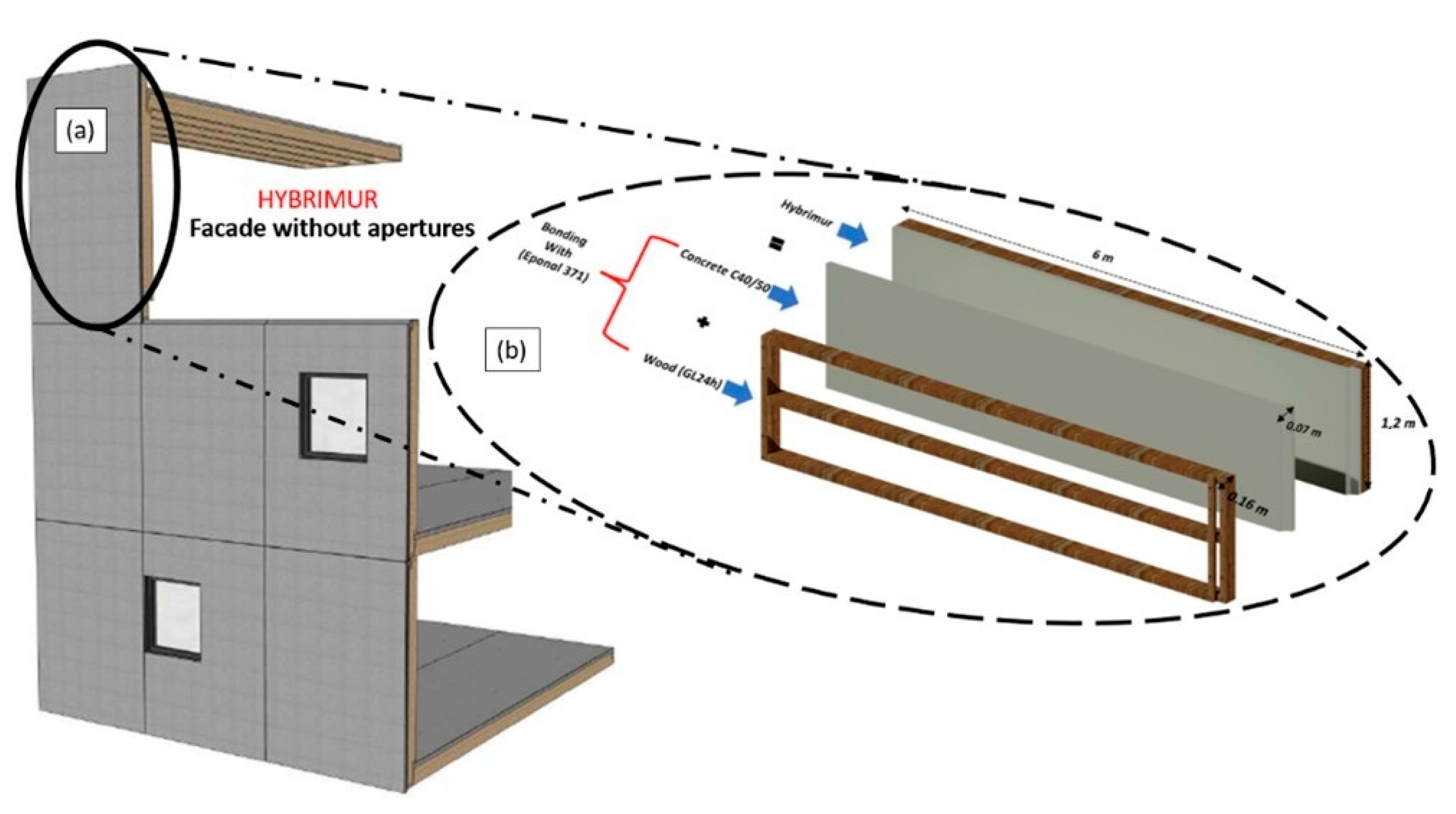
The test panel design is depicted in Figure 4. Each panel, fabricated by the company Cruard, has dimensions of 6 m in length and 1.2 m in width. The panels consist of a 7 cm thick concrete layer and a 16 cm thick timber layer, designed to reduce overall weight and minimize greenhouse gas emissions. Two configurations were evaluated: one incorporating fiber reinforcement and insulation, and another without these components. Fibers were incorporated into the concrete matrix as an alternative to conventional reinforcement techniques. The panels were bonded using Eponal epoxy adhesive, as outlined by Augeard et al. [10]. It is important to note that, in practical applications, the timber layer is oriented towards the interior of the building, while the concrete layer is exposed to external environmental conditions. In order to increase the safety in case of later debonding of the concrete layer, the concrete cross-section is increased on the top of the panel by a timber cross-section reduction. This does not modify the interface properties of Figure 1, since it is only on one side of the panel and full bonding of the concrete is obtained on the length of the panel. The boundary conditions are not modified in comparison to Figure 1. This issue concerns only safety. The analytical model does not consider the end-concrete properties, while they are considered in the FEM model.
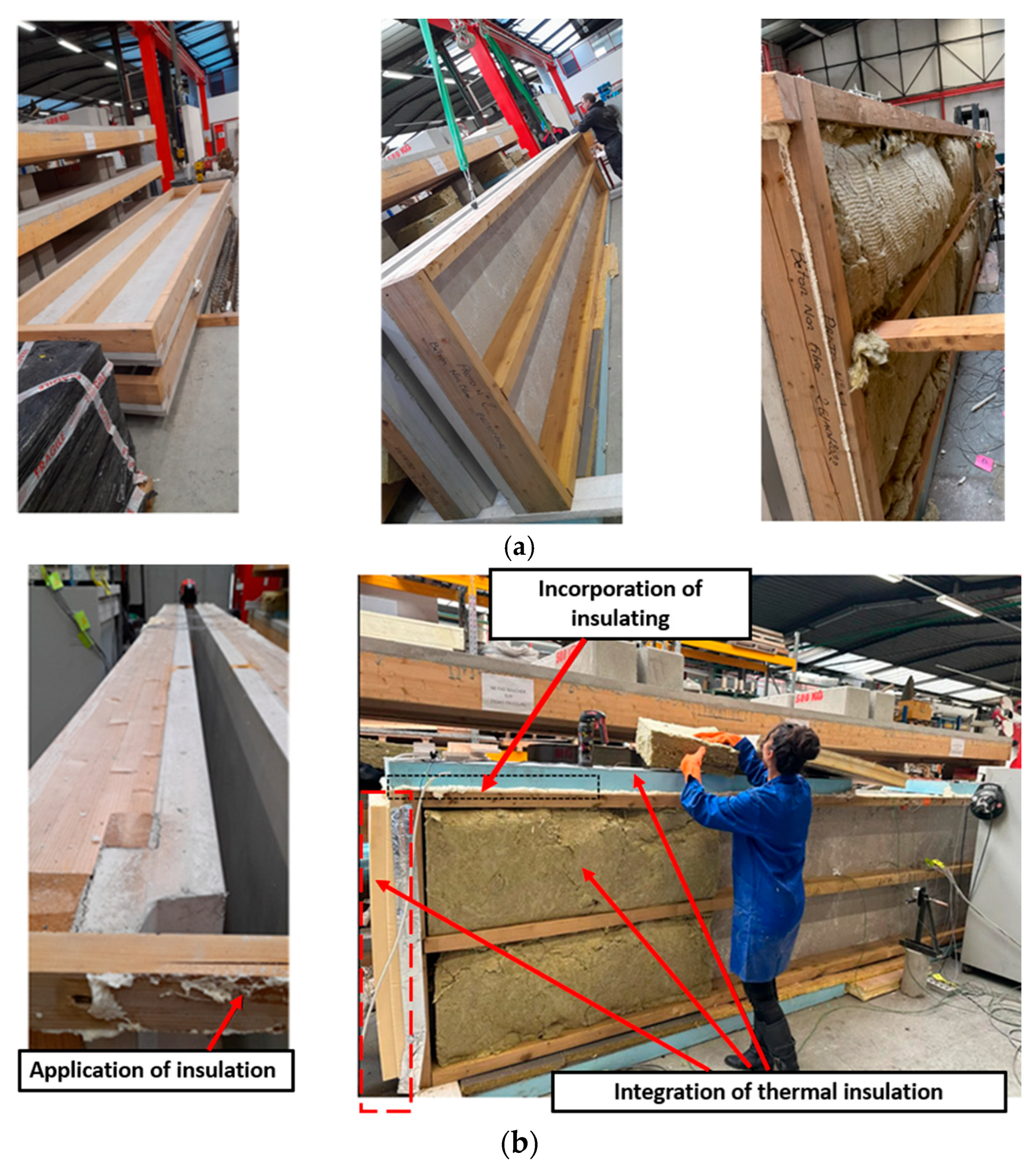
The testing conditions for this configuration are illustrated in Figure 5b and Table 2. The tests were conducted in a laboratory setting, where two panels were positioned opposite each other to ensure consistent test repeatability and maximize efficiency. During the testing, the wood side of the panels was exposed to ambient air, while the inner concrete surface was heated to 70 °C, creating a temperature gradient of 50 °C.
This high temperature ensures that the thermal gradient across the composite panel is sufficiently large to generate measurable thermal strains and stresses at the wood–concrete interface. The 50 °C gradient between the heated concrete and ambient wood surface reflects realistic environmental conditions during summer peaks or in regions with high solar exposure, allowing the investigation of thermally induced mechanical effects that the façade would face in service. Using these temperatures also tests the adhesive bonding performance under extreme but plausible thermal loading, which is critical for validating the durability and safety of the proposed hybrid façade system.
Upon reaching this temperature, the tests were paused to apply glass wool insulation around the panels, both to evaluate its effectiveness and to achieve a more uniform temperature distribution across the panels. To further optimize the insulation, additional cut panels and insulating foam were placed on top of the heated panels. The cooling phase of each panel was monitored and recorded. After this, the tests were resumed to assess the effect of the insulation on the thermal performance of the façade.

4.2. Instrumentation

4.2.1. Temperature Sensors

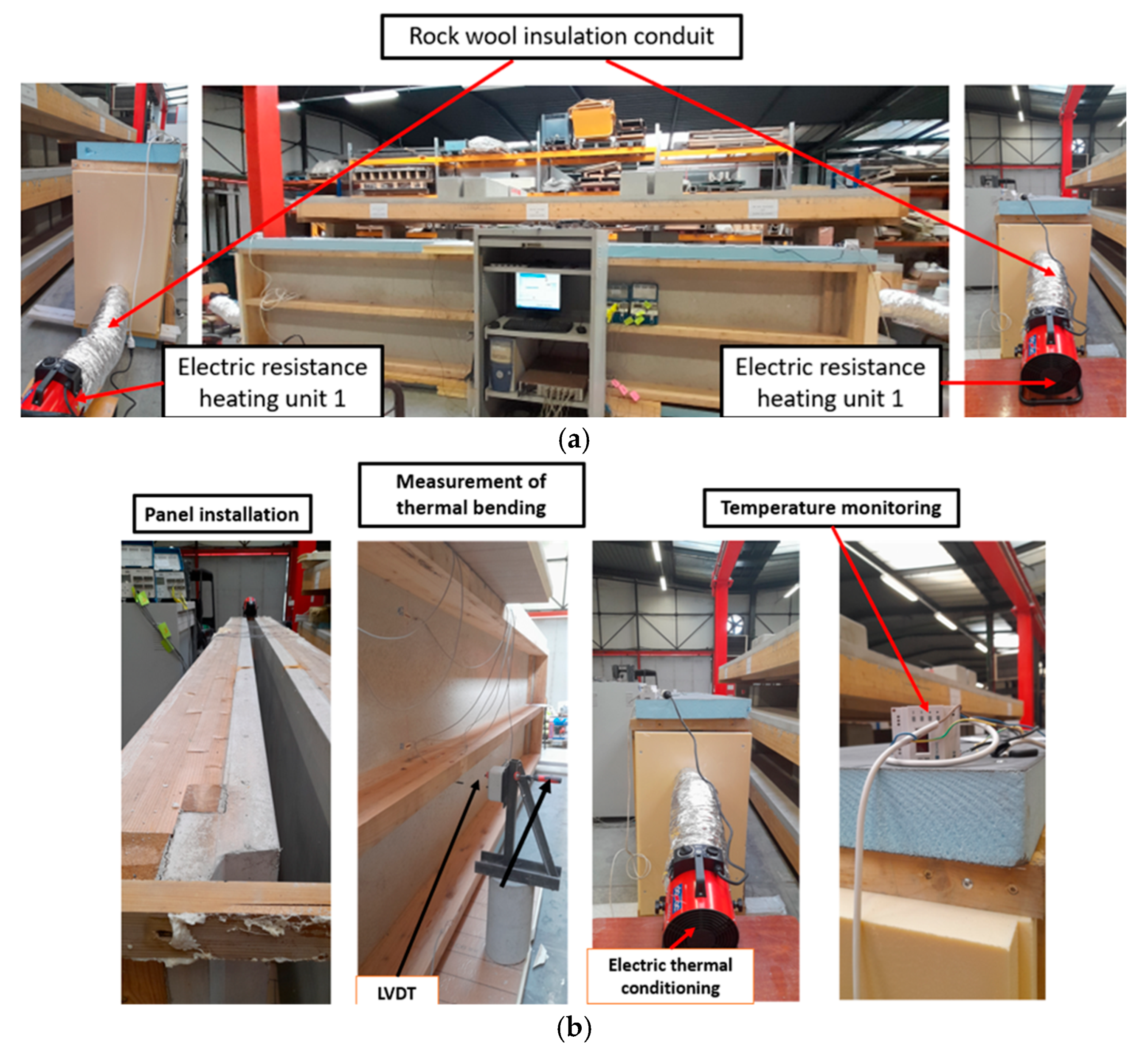
For this study, the panels were subjected to heating using two 3.0 kW electric heaters, each equipped with spiral heating elements. This configuration was chosen to ensure uniform and efficient heat distribution, even in confined spaces. The electric heaters are equipped with an integrated thermostat and an adjustment knob for precise temperature control. They feature a multi-position switch that allows for selection between two heating powers (1.5 kW or 3.0 kW) and a fan mode. The blow angle can be adjusted from 0 to 20°, with an airflow rate of 286 m3/h. To optimize heat distribution across the panels, the heaters were positioned at the ends of the panels. Heat transfer to the panels was facilitated through soundproofed rock wool ducts, compliant with standard M1, with a diameter of 200 mm and a length of 10 m. These ducts effectively channel the hot air while providing sound insulation. The thermal gradient was controlled using the H-Tronic HTS 1000 device. The thermal switch was strategically positioned and connected to the heaters at the ends of the panels to ensure precise regulation of heat distribution. K-type temperature sensors were installed to measure the temperature gradient. One sensor was placed on the concrete that was exposed to the ambient laboratory temperature (K1), and another sensor was positioned on the heated concrete (K2). This setup allows for accurate monitoring of the thermal gradient variations between the unheated and heated concrete surfaces. All components and their placements in this setup are illustrated in Figure 6. Additionally, temperature measurements from thermocouple K1 (on the timber side Figure 7) remained close to ambient conditions (Figure 8), indicating that the wood was not significantly thermally affected. Therefore, orthotropic thermal and mechanical effects were considered negligible in this context.

4.2.2. LVDT and Strain Gauges

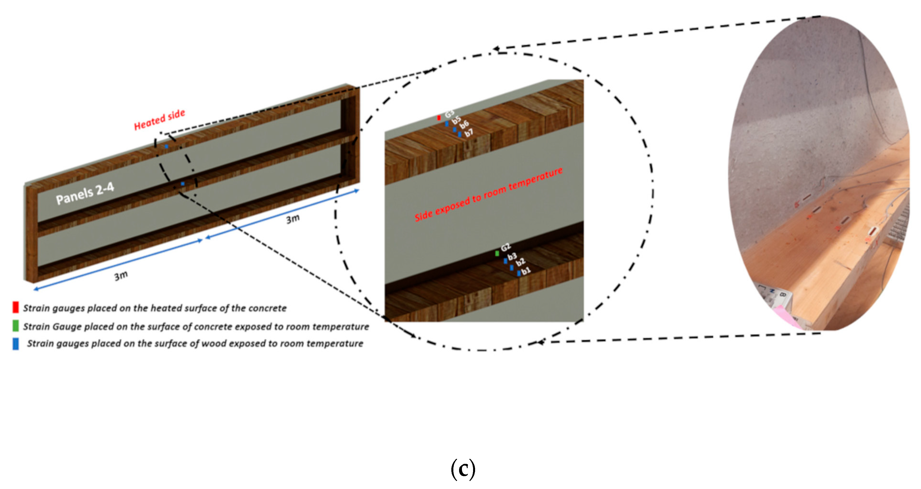
To evaluate thermal expansion, three 30 mm strain gauges were installed on the wooden sections of the panel (Figure 7 and Table 3). One strain gauge was placed on the cooled concrete, another on the heated concrete, and an additional gauge was positioned on the outer surface of the concrete exposed to the ambient environment. The specific locations of these gauges are illustrated in Figure 7. The following table provides a summary of the gauge locations and their designations on each panel.
The temperature evolution over time on both the heated and unheated concrete surfaces was continuously recorded using the K-type sensors, providing detailed data on the thermal gradient development during the tests (Figure 8).

5. Results and Discussion

5.1. Analysis of Theoretical Results

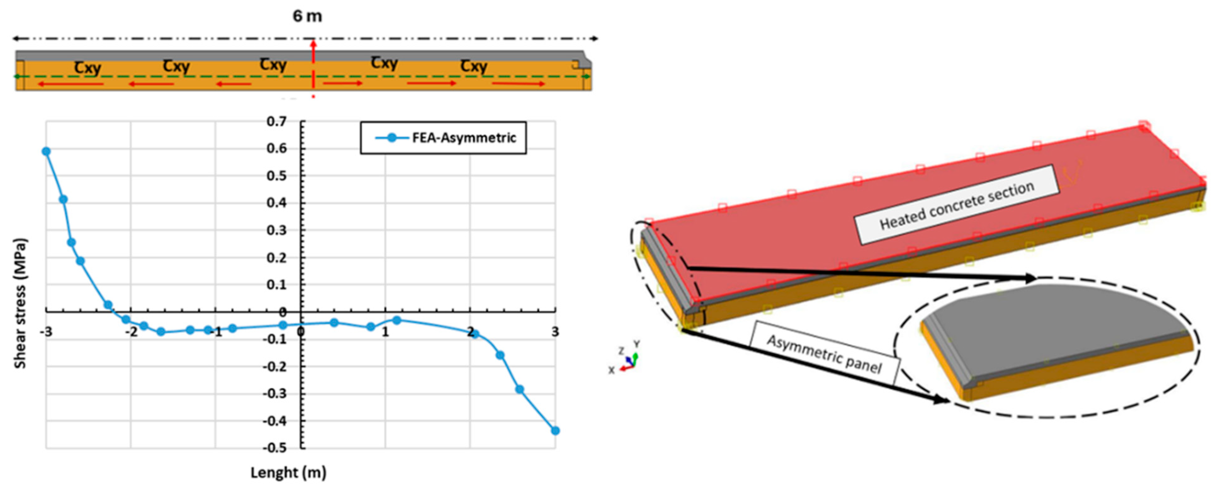
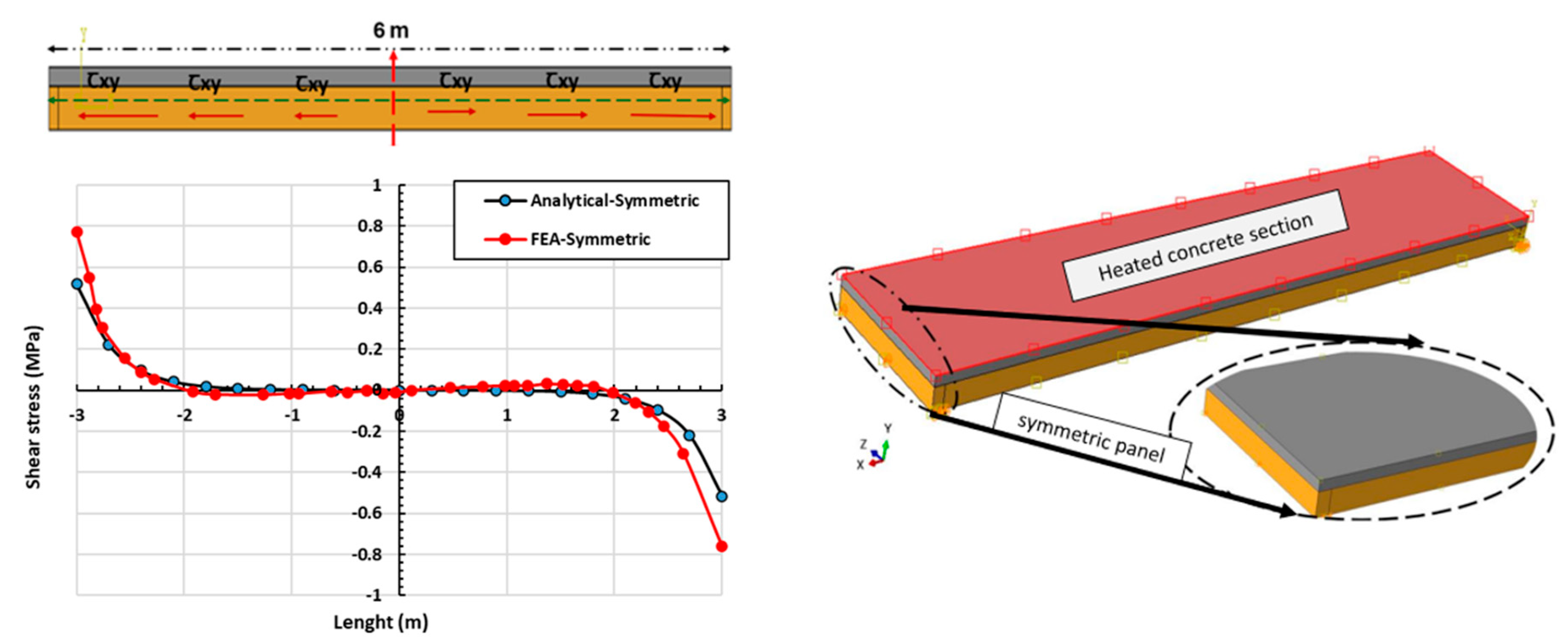
To better understand the shear stress behavior under thermal loading, two panel configurations were modeled: an asymmetric panel, representing the actual prefabricated configuration, and a symmetric panel, used to isolate the influence of geometric symmetry on stress distribution. The asymmetric panel (see Figure 9) reflects the real construction scenario, in which the concrete face is slightly offset from the timber layer to accommodate geometric tolerances and alignment along the building façade. This configuration results in non-uniform thermal loading and mechanical boundary conditions, leading to an asymmetric distribution of shear stress (in red on Figure 9 and Figure 10). In contrast, the symmetric panel (see Figure 10) is an idealized model with perfectly aligned, identical layers, ensuring geometric and material symmetry. This reference case allows a clearer interpretation of the effects that were induced purely by asymmetry.
Importantly, the thermal loading conditions applied in the simulations were not assumed arbitrarily. They were directly derived from experimental measurements. The temperature evolution over time, recorded during the heating tests, is presented in Figure 8 and served as a basis for defining the time-dependent thermal gradients implemented in the numerical models.
The shear stress distributions along the length of the façades are depicted in Figure 9 and Figure 10, which also include the finite element modeling results for the beams. Initially, we focus on the shear stress values obtained from finite element simulations and theoretical calculations for a temperature gradient of 50 °C. Table 4 summarizes the evolution of shear stress for both models at various points on the panel. A comparative analysis of the shear stress results derived from finite element simulations and theoretical modeling was conducted. The maximal shear stress was 48%, according to the value obtained through finite element analysis. Table 4 provides a detailed summary of the shear stresses under a thermal gradient of 50 °C. A discrepancy between the theoretical and finite element results is evident, ranging from 20% to 32%. Notably, the numerical simulation closely replicates the theoretical deformation profile, with shear stress values at the edges measured at 0.52 MPa analytically and 0.77 MPa through finite element analysis (refer to Figure 9). Analysis of both surfaces indicates that shear stresses are greatest at the edges and decrease to zero along the bonded length of the panel, consistent with expectations for a bonded connection. Additionally, it is important to note that the temperature distribution is simplified and idealized in the theoretical model, with the system assumed to be perfectly insulated. For the asymmetric panel shown in Figure 10, the analysis of the thermo-mechanical behavior of the façade demonstrates a distinct response compared to the initial tests. The stress profile exhibits a notably asymmetric distribution, with shear stress values at the edges ranging from 0.6 MPa to 0.4 MPa. Moreover, the shear stress does not tend to be zero along the length of the panel, as shown in Figure 10. This behavior is attributed to the non-uniform thermal loading applied to the asymmetric configuration, in contrast to the uniform distribution used in symmetric panels. The comparison highlights how symmetry in geometry and thermal loading affects stress distribution. In the asymmetric case, experimental results confirm an uneven shear stress profile, differing from the expected symmetric behavior.
These findings emphasize the importance of maintaining uniform thermal loading in panel design, as it significantly influences the mechanical response under thermal stress. Analysis of both surfaces indicates that the shear stresses are maximal at the edges and decrease to zero along the bonded length of the panel, which is consistent with expectations, given the bonded nature of the connection. It is also important to note that in the theoretical modeling, the temperature distribution is simplified and idealized, with the system considered to be perfectly insulated. For the asymmetric panel illustrated in Figure 9, the analysis of the thermo-mechanical behavior of the façade reveals a distinct response compared to the initial tests performed. The stress profile shows a marked asymmetric distribution, with shear stress values at the edges ranging from 0.6 MPa to 0.4 MPa.
Furthermore, the shear stress does not tend to cancel out along the length of the panel. This observation can be attributed to a non-uniform application of the thermal loading, unlike the homogeneous distribution applied to the symmetric panels. The comparison between symmetric and asymmetric panels highlights the influence of symmetry on the distribution of stresses under thermal loading (Figure 9); the experimental results reveal an asymmetric distribution of stresses, contrary to the expected distribution for symmetric panels. These observations underscore the crucial importance of thermal loading uniformity in the design and analysis of panels, as it directly affects their mechanical behavior under thermal stress.

5.2. Validation of the Numerical Model

5.2.1. Temperature Gradient (∆T) Results

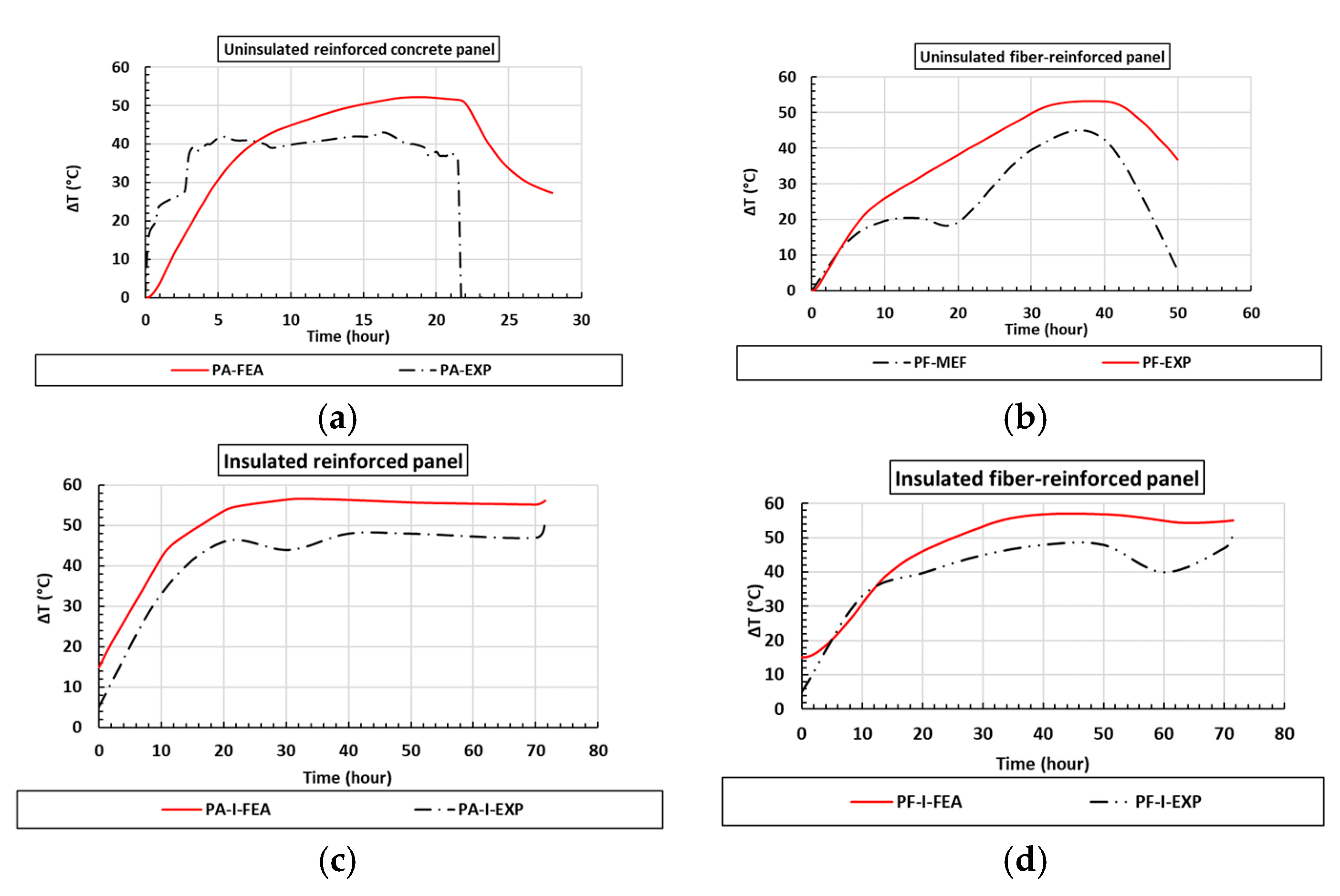
Figure 11 shows the variation in the temperature gradient ∆T (°C) at the interface between the wood and concrete for two types of concrete: reinforced (PA) and fiber-reinforced (PF). According to the results summarized in Table 5, the discrepancies between the numerical values and those measured during thermal expansion tests range from −8% to −19%. For the uninsulated reinforced panel (Figure 11a), the temperature gradient at the interface reached 51 °C, which aligns closely with the experimentally generated gradient. The temperature increase was uniform and linear, rising to 43 °C during the heating phase and then decreasing to 29 °C during the cooling phase. When compared to the experimental curve, there is a noticeable increase in the temperature gradient of up to 10 °C, which is inconsistent with the numerical thermal gradient that continues to rise over time. In the case of the uninsulated fiber-reinforced panel (Figure 11b), the numerical temperature gradient at the interface was 51 °C while, experimentally, it was 42 °C—indicating a 9 °C difference. This discrepancy suggests that the numerical simulation yields a higher temperature gradient than that observed experimentally.
One possible explanation for this overestimation lies in the assumptions made regarding material behavior, particularly the isotropic assumption for the wood in the numerical model. The real anisotropic and fibrous nature of wood can cause non-uniform heating and localized temperature variations that are not captured when assuming isotropy. This simplification affects the heat transfer predictions at the wood–concrete interface and likely contributes to the higher temperature gradients predicted by the model. Other parameters, such as linear elasticity, constant wall temperature, or an absence of shrinkage/creep, may modify the results; shrinkage and creep may exert the greatest influence on the results.
Moreover, other factors contribute to these differences, including variability in experimental heating durations (ranging from 20 to 70 h) and the idealized boundary and initial conditions assumed in the simulations. From the experimental point of view, the outside temperature could change slightly during the night that may cause some small differences between modeling and experimental results (Figure 11). It is also possible to think that perfect insulation of the panel is idealized in modeling, which is more difficult to do in real experiments.
These cause the numerical model to exhibit a more uniform and continuous increase in temperature gradient, whereas experimental results show thermal lag and fluctuations. The inclusion of insulation (Figure 11c,d) resulted in increases of 5 °C for the fiber-reinforced panel and 6 °C for the reinforced panel. Two distinct phases were considered: the heating phase and the transient regime. Overall, while the isotropic wood assumption is a reasonable simplification, incorporating anisotropic thermal properties in future models could improve the accuracy of the predicted temperature gradients and reduce discrepancies between numerical and experimental results.
Figure 12 illustrates the isotherms of the steady-state temperature gradients generated across all facades. It is evident that for the insulated facades, the temperature distribution at the interface is considerably higher, ranging from 65 °C to 68 °C.

5.2.2. Thermal Bending

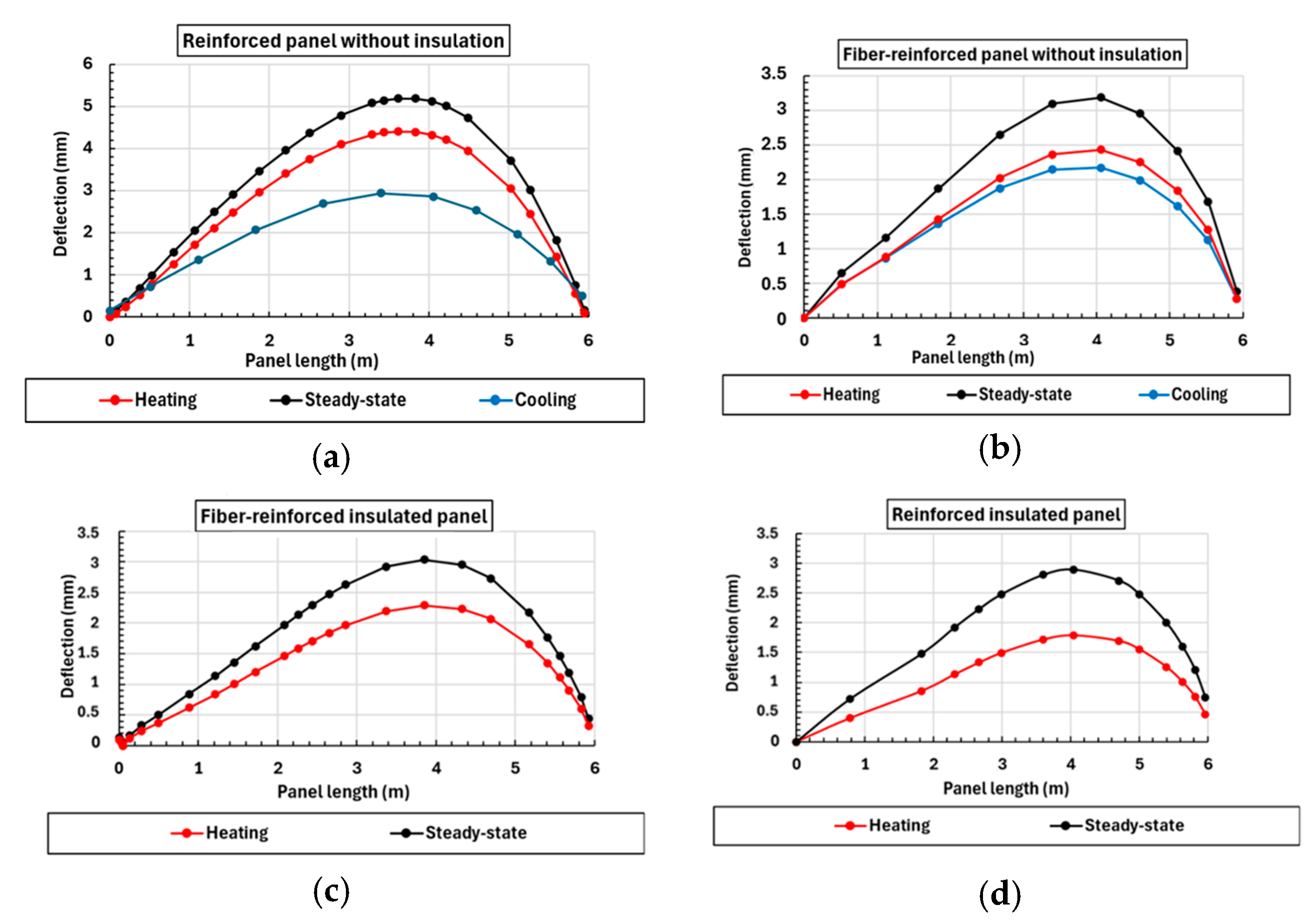
Figure 13 illustrates the vertical displacement along the panel length. All panels exhibit deformation in response to the applied thermal load. Due to the clamped boundary conditions at the ends ( u x = u y = u z = u R x = u R y = u R z = 0), displacements are constrained to zero at these fixed ends and reach a maximum at 4 m along the length, as opposed to 3 m, aligning with the observed structural asymmetry of the panels. Additionally, thermal deflections were measured at the midpoint of the panel’s length on the heated side of the concrete.
It is also observed from the curves that a residual displacement remains at the free end of the heated panel, with deformation amplitudes between 0.3 mm and 0.5 mm. This residual deformation indicates that the panel does not fully recover its original shape upon cooling, which may suggest viscoelastic or irreversible deformation behavior in the wood–concrete system, possibly due to the differential thermal expansion and the anisotropic properties of timber.
The comparison between numerical and experimental values during thermal expansion tests reveals discrepancies ranging from 30% to 67%, particularly in the early stages. While these differences may seem large, they are expected, given the idealized assumptions in the numerical model (such as perfect material homogeneity and simplified boundary conditions). For instance, in the absence of insulation (Figure 13a), the numerically predicted deflection for the reinforced panel was 5 mm, while the experimental result was 1.9 mm: a difference of 62%. This mismatch could be attributed to an underestimation of the stiffness or thermal inertia in the model or to moisture effects not accounted for numerically. It is also important to note that the model is a tentative finite element model and only considers isotropic wood; this limits the accuracy of the results obtained by the model.
Despite these discrepancies, the maximum deflections remained below the serviceability limit (L/300 = 20.0 mm) defined by the Eurocode 5 standard. However, several test cases reached up to 68% of this threshold, indicating that even thermal loading alone, without mechanical load, can produce substantial deflections. This highlights the importance of accounting for thermal effects in serviceability design, especially in hybrid structures with dissimilar materials.
The addition of thermal insulation was shown to significantly reduce deflections. In the case of the reinforced panel (Figure 13c), deflection dropped to 2.1 mm with insulation compared to 5 mm without. This demonstrates the effectiveness of insulation in limiting thermal bowing by slowing the temperature gradient and thereby reducing differential expansion between the layers.
Interestingly, in the case of fiber-reinforced panels (Figure 13b), the deflection difference between insulated and non-insulated cases was only 0.1 mm, suggesting that panel stiffness or reinforcement distribution plays a greater role in thermal deformation behavior than insulation alone.
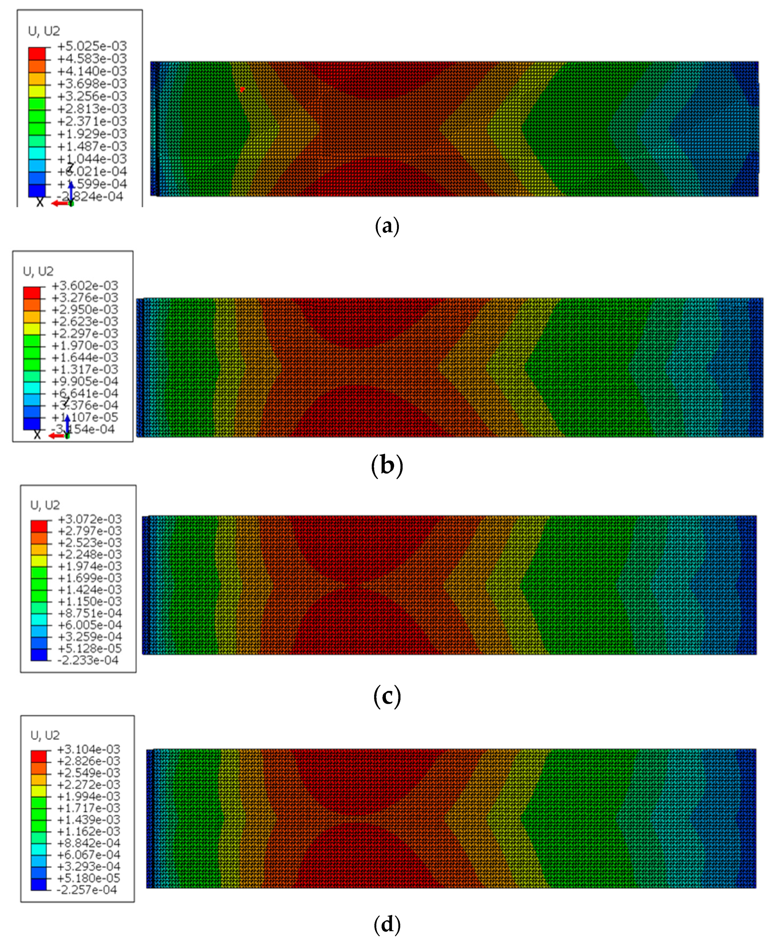
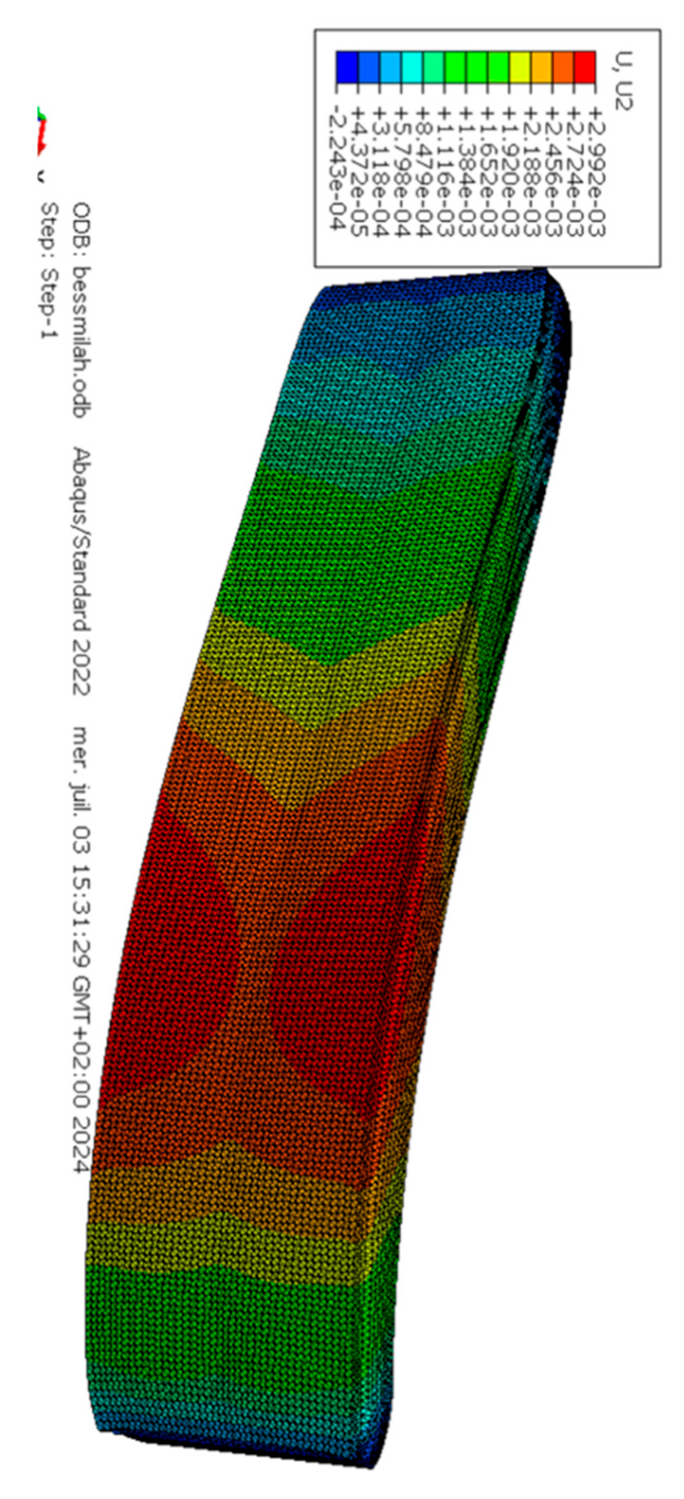
Additionally, Figure 14 and Figure 15 show minimal vertical displacement variations during the steady-state regime, with only about 1 mm fluctuation during heating and cooling transitions. This behavior confirms that most deformation occurs during the transient phase, reinforcing the need to consider time-dependent thermal loading in design and analysis.
It is noted that, for the uninsulated panels, the maximum deflection occurs primarily near the edges of the panel. In contrast, for the insulated panels, the maximum deflection is closer to the center of the panel. This phenomenon reflects the thermal distribution in the heated area of the concrete and confirms the hypothesis that displacements are concentrated in the less asymmetric regions of the panel, as illustrated by the displacement isotherms. This shift in the deflection peak location highlights how insulation affects the heat transfer path and the resulting thermal gradient. In uninsulated configurations, the rapid edge heating leads to localized thermal expansion, causing greater edge deflection. In contrast, insulation promotes a more gradual and uniform temperature profile across the panel width, shifting the expansion-induced bending towards the center.

5.2.3. Thermal Strains

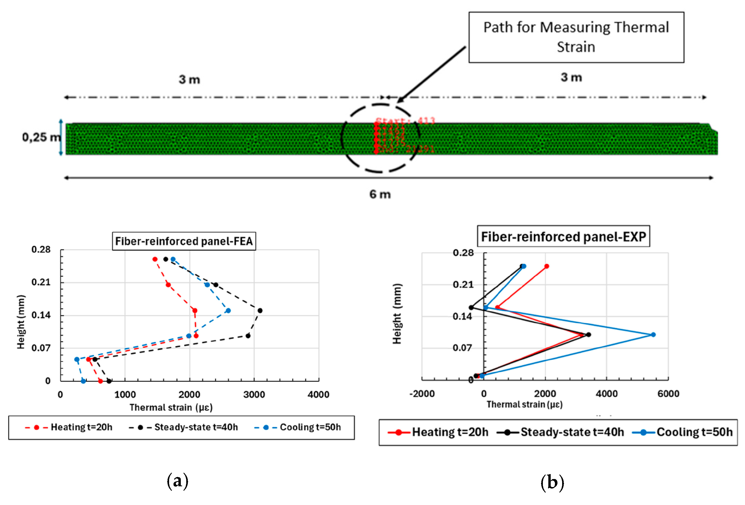
To monitor the evolution of thermal strains, a path was established along the height of the panel, as depicted in Figure 16. Strain tracking was performed under three conditions: heating phase, steady state, and cooling phase, as illustrated in Figure 17. Throughout these phases, an increase in thermal strains was consistently observed at the interface between the concrete and wood for all panels—both fiber-reinforced and reinforced, irrespective of the presence of insulation—except for the uninsulated reinforced concrete panel, which exhibited divergent behavior during the heating phase. For the fiber-reinforced panel without insulation (Figure 17a), numerical simulations indicate a slight increase in thermal strains, remaining within the range of 2099 to 2082 µε, while experimental results estimate thermal strains of 3403 µε. During the steady state, numerical simulations show thermal strains of 2903 µε at the interface compared to 3403 µε in experimental observations (Figure 16b). In the cooling phase, numerical strains decrease to 2598 µε, while experimental measurements reveal a continuous increase in strains, reaching 5506 µε. This observed discrepancy is rational, as concrete retains heat and has not fully cooled. Finite element modeling shows a global expansion of both wood and concrete, whereas experiments reveal localized compression in the concrete, ranging between −57 µε and 187 µε during the heating and cooling phases. This compression is evident in Figure 16, where thermal strain isovalues (E33) show strains reaching −75 µε in the concrete. For the fiber-reinforced panel with insulation (Figure 16c), both experimental and numerical results show comparable levels of expansion, varying from 305 µε to 426 µε in the concrete during heating and steady-state regimes. At the adhesive joint, numerical simulations show an increase in strain from 3192 µε to 3762 µε, while experimental results indicate a nearly constant strain of 5039 µε in both regimes (Figure 16d). Experimental observations of the cooled section of the wood (Figure 16d) reveal compression, with strain decreasing from −445 µε to −253 µε during heating, and increasing from −445 µε to −564 µε during the steady-state regime. Conversely, the modeling indicates expansion up to 766 µε. As previously mentioned, the wood was modeled as isotropic in the numerical simulations. However, this discrepancy can be partly attributed to the fibrous and anisotropic nature of wood, which may cause non-uniform heating and localized contraction in some areas, while other regions expand. During heating, the non-uniform temperature distribution likely explains the decrease in strain, whereas the steady-state regime reflects more uniform heating and expansion. Similar trends are observed for the reinforced panel (Figure 16e), with comparable tension levels in both numerical and experimental results at the interface. During the heating regime, numerical thermal strain increases from 634 με to 911 με and, in the steady-state regime, it rises from 911 με to 1041 με. Figure 16f highlights areas of both tension and compression in the wood that arise during heating and steady-state regimes, which are due to its fibrous structure. Additionally, in the heated concrete, compression up to −343 με is observed, contrasting with numerical tension estimated at 400 με.

6. Conclusions

This study has provided new insights into the thermo-mechanical behavior of adhesively bonded wood–concrete façade panels subjected to significant thermal gradients. The experimental investigation, supported by analytical and numerical modeling, demonstrated that thermal effects alone can induce measurable strains, bowing, and interface stresses without necessarily causing failure. Fiber-reinforced concrete panels exhibited greater compatibility with timber than traditionally reinforced panels, as reflected in reduced temperature gradients, lower strains, and improved deflection control. The addition of insulation primarily altered the timing of thermal responses rather than their magnitude, though it proved effective in limiting thermal bowing in reinforced panels.
Discrepancies between experimental and numerical results underline the limitations of simplified assumptions, particularly the isotropic modeling of wood and idealized boundary conditions. More advanced models that incorporate the anisotropy of timber, nonlinear adhesive behavior, and time-dependent effects such as creep and moisture variations are needed to improve prediction accuracy.
Overall, the findings emphasize that thermal lag, reinforcement type, and material compatibility are decisive factors in the serviceability of hybrid façades. Extreme deflections observed under thermal gradients, even in the absence of mechanical loading, highlight the necessity of explicitly accounting for thermal effects in structural design. Future work should expand this research to long-term environmental exposure, including moisture cycles and combined thermo-mechanical loading, to fully assess the durability and reliability of bonded hybrid façades. The discrepancies between simulations and experiments highlight the limitations of simplified modeling approaches, particularly regarding adhesive joints, boundary conditions, and the anisotropic properties of wood. Incorporating temperature-dependent and nonlinear material behavior would likely improve prediction accuracy.
Overall, the results confirm that thermal lag, rather than maximum gradient, governs deformation patterns. They also underline the importance of reinforcement type in hybrid systems, as fiber-reinforced concrete demonstrated more favorable thermal compatibility with wood. Finally, the extreme deflections observed without mechanical loading stress the need to treat thermal effects as a fundamental factor in structural design. Future work should include the role of moisture and creep in both wood and concrete. From a structural perspective, moisture-induced dimensional variations generate additional stresses in composite systems, especially in bonded wood–concrete assemblies where differential movements may affect the integrity of the adhesive interface. Over time, repeated wetting and drying cycles can accelerate creep and compromise durability.

Author Contributions

Data curation, Formal analysis, Writing—original draft, R.A.; Writing—review and editing, Methodology, L.M.; Supervision, Writing—review and editing, E.F. All authors have read and agreed to the published version of the manuscript.

Funding

French Environmental agency ADEME, project Hybridal.

Data Availability Statement

The original contributions of this study are included in the article Further inquiries can be directed to the corresponding author.

Acknowledgments

The authors would like to express their gratitude to the French agency ADEME for the financial support of the Hybridal 2 project, and to the companies CRUARD Charpente and Jousselin for their assistance in preparing the test specimens.

Conflicts of Interest

The authors declare no conflicts of interest.

Nomenclature

symboldescriptionunits
a 2 ratio of the composite to the non-composite moment of inertia
β 2 equal to 1 − α2.
ΔTthe temperature differential in the sandwich panel (T2–T1).°C
ϕflexionslip due to bendingmm/mm
Φ a x i a l 1 slip due to axial deformation in the top layer.mm
τthe shear stress in the middle layer of the intermediate layerMPa
xabscissa measured from mid-span.mm
υbowing due to temperature differentialmm
A 1 area of the top layermm2
E b modulus of elasticity of the woodMPa
E c modulus of elasticity of the concreteMPa
I 1,2 moment of inertia. Indices 1 and 2 represent the top and bottom walls, respectivelymm4
M a x i a l sum of the moments in the two wallsN.mm
M b e n d i n g sum of the moments in the two walls due to the panel’s curvatureN.mm
M t h e r m a l bending moment due to temperature change.N.mm
t 1 thickness of the heated wythemm
t 2 thickness of the unheated wythemm
Kstiffness per unit areaN/mm
r1distances from the centroids of the heated and unheated wythesmm
r2distances from the centroids of the unheated and unheated wythesmm
rdistance between the axis of the walls and the centroid of the cross-sectional areamm

References

  1. Richart, F.E.; Williams, C.B. Tests of Composite Timber and Concrete Beams; Bulletin, no. 343; University of Illinois at Urbana Champaign, College of Engineering. Engineering Experiment Station: Champaign, IL, USA, 2007; Available online: https://hdl.handle.net/2142/4444 (accessed on 10 September 2025).
  2. Yeoh, D.; Fragiacomo, M.; De Franceschi, M.; Heng Boon, K. State of the art on timber-concrete composite structures: Literature review. J. Struct. Eng. 2011, 137, 1085–1095. [Google Scholar] [CrossRef]
  3. Rodrigues, J.N.; Dias, A.M.P.G.; Providência, P. Timber-concrete composite bridges: State-of-the-art review. BioResource 2013, 8, 6630–6649. Available online: https://bioresources.cnr.ncsu.edu/resources/timber-concrete-composite-bridges-state-of-the-art-review/ (accessed on 10 September 2025). [CrossRef]
  4. Weaver, C.A.; Davids, W.G.; Dagher, H.J. Testing and analysis of partially composite fiber-reinforced polymer-glulam-concrete bridge girders. J. Bridge Eng. 2004, 9, 316–325. [Google Scholar] [CrossRef]
  5. Parisi, M.A.; Piazza, M. Restoration and Strengthening of Timber Structures: Principles, Criteria, and Examples. Pract. Period. Struct. Des. Constr. 2007, 12, 177–185. [Google Scholar] [CrossRef]
  6. Naito, C.J.; Hoeman, J.M.; Shull, J.S.; Saucier, A.; Salim, H.A.; Bewick, B.T.; Hammons, M.I. Precast/Prestressed Concrete Experiments Performance on Non-Load Bearing Sandwich Wall Panels; Air Force Research Laboratory, Materials and Manufacturing Directorate, Tyndall Air Force Base: Bay County, FL, USA, 2011. [Google Scholar] [CrossRef]
  7. Pozza, L.; Scotta, R.; Polastri, A.; Ceccotti, A. Seismic behaviour of wood-concrete frame shear-wall system and comparison with code provisions. In Proceedings of the Meeting 45 of the Working Commission W18-Timber Structures, Växjö, Sweden, 27–30 August 2012; Available online: https://hdl.handle.net/11577/2525153 (accessed on 10 September 2025).
  8. Pham, H.S. Optimisation et Comportement en Fatigue de la Connexion Dois-BFUP pour de Nouveaux Ponts Mixtes. Ph.D. Thesis, Ecole Nationale des Ponts et Chaussées, Marne-la-Vallée, France, 2007. [Google Scholar]
  9. Gutkowski, R.; Brown, K.; Shigidi, A.; Natterer, J. Laboratory tests of composite wood–concrete beams. Constr. Build. Mater. 2008, 22, 1059–1066. [Google Scholar] [CrossRef]
  10. Augeard, E.; Michel, L.; Ferrier, E. Experimental and analytical study of the mechanical behavior of heterogeneous glulam–concrete beams and panels assembled by a specific treatment of wood. Constr. Build. Mater. 2018, 191, 812–825. [Google Scholar] [CrossRef]
  11. Glass, S.V.; Zelinka, S.L. Moisture relations and physical properties of wood. In Wood Handbook: Wood as an Engineering Material: Chapter 4, Centennial ed.; U.S. Department of Agriculture, Forest Service, Forest Products Laboratory: Madison, WI, USA, 2010; pp. 1–4. Available online: https://research.fs.usda.gov/treesearch/37428 (accessed on 10 September 2025).
  12. Ge, H.; Tariku, F. Evaluation of the thermal performance of innovative pre-fabricated wall systems through field testing. In Proceedings of the Building Enclosure Science & Technology (BEST3) Conference, Atlanta, GA, USA, 2–4 April 2012. [Google Scholar]
  13. Sorensen, T.J.; Thomas, R.J.; Dorafshan, S.; Maguire, M. Thermal bridging in concrete sandwich walls. ACI Concr. Int. 2018, 40, 45–49. Available online: https://scholarsarchive.byu.edu/facpub/5519 (accessed on 10 September 2025).
  14. Keena, N.; Raugei, M.; Lokko, M.; Aly Etman, M.; Achnani, V.; Reck, B.K.; Dyson, A. A Life-cycle approach to investigate the potential of novel biobased construction materials toward a circular built environment. Energies 2022, 15, 7239. [Google Scholar] [CrossRef]
  15. Frenette, C.D.; Bulle, C.; Beauregard, R.; Salenikovich, A.; Derome, D. Using life cycle assessment to derive an environmental index for light-frame wood wall assemblies. Build. Environ. 2010, 45, 2111–2122. [Google Scholar] [CrossRef]
  16. Pérez-García, A.; Víllora, A.G.; Pérez, G.G. Building’s eco-efficiency improvements based on reinforced concrete multilayer structural panels. Energy Build. 2014, 85, 1–11. [Google Scholar] [CrossRef]
  17. Martins, C.; Dias, A.M.P.G.; Costa, R.; Santos, P. Environmentally friendly high performance timber–concrete panel. Constr. Build. Mater. 2016, 102, 1060–1069. [Google Scholar] [CrossRef]
  18. Du, H.; Hu, X.; Xie, Z.; Wang, H. Study on shear behavior of inclined cross lag screws for glulam-concrete composite beams. Constr. Build. Mater. 2019, 224, 132–143. [Google Scholar] [CrossRef]
  19. Clouston, P.; Schreyer, A. Design and use of wood–concrete composites. Pract. Period. Struct. Des. Constr. 2008, 13, 167–174. [Google Scholar] [CrossRef]
  20. Branco, J.M.; Cruz, P.J.S.; Piazza, M. Experimental analysis of laterally loaded nailed timber-to-concrete connections. Constr. Build. Mater. 2009, 23, 400–410. [Google Scholar] [CrossRef]
  21. Ferrier, E.; Labossière, P.; Neale, K.W. Mechanical behavior of an innovative hybrid beam made of glulam and ultrahigh-performance concrete reinforced with frp or steel. J. Compos. Constr. 2010, 14, 217–223. [Google Scholar] [CrossRef]
  22. Ferrier, E.; Labossière, P.; Neale, K.W. Modelling the bending behaviour of a new hybrid glulam beam reinforced with frp and ultra-high-performance concrete. Appl. Math. Model. 2012, 36, 3883–3902. [Google Scholar] [CrossRef]
  23. Leabu, V.F. Problems and performance of precast concrete wall panels. J. Proc. 1959, 56, 287–298. Available online: http://www.ijret.org (accessed on 10 September 2025).
  24. Mai, Y. Performance Evaluation of Sandwich Panels Subjected to Bending Compression and Thermal Bowing; Materials and Structures; Springer: Berlin/Heidelberg, Germany, 1980; Volume 13, pp. 159–168. [Google Scholar] [CrossRef]
  25. Losch, E.; Hynes, P.W.; Andrews, R.; Browning, R.; Cardone, P.; Devalapura, R.K.; Donahey, R.C.; Freedman, S.; Gleich, H.A.; Goettsche, G.E.; et al. State of the Art of Precast/Prestressed Concrete Sandwich Wall Panels; PCI Journal: Chicago, IL, USA, 2011; pp. 131–176. [Google Scholar]
  26. Sorensen, T.; Dorafshan, S.; Maguire, M. Thermal Evaluation of Common Locations of Heat Loss in Sandwich Wall Panels. In Proceedings of the Congress on Technical Advancement 2017, Duluth, MN, USA, 10–13 September 2017; pp. 173–184. [Google Scholar]
  27. Ghali, A.; Favre, R. Concrete Structures: Stresses and Deformations, 3rd ed.; First Published 2002, eBook Published 8 October 2018; CRC Press: London, UK, 2002; 608p, ISBN 9781315273389. [Google Scholar] [CrossRef]
  28. Maguire, M.; Roberts-Wollmann, C.; Cousins, T. Live-Load Testing and Long-Term Monitoring of the Varina-Enon Bridge: Investigating Thermal Distress. J. Bridge Eng. 2018, 23, 04018003. [Google Scholar] [CrossRef]
  29. Losch, E. Bowing of Insulated Precast Concrete Wall Panels. PCI J. 2003, 126–129. [Google Scholar]
  30. Hoffmeister, B.; Di Biase, P.; Richter, C.; Feldmann, M. Innovative steel-glass components for high-performance building skins: Testing of full-scale prototypes. Glass Struct. Eng. 2017, 2, 57–78. [Google Scholar] [CrossRef]
  31. Guitard, D.; El Amri, F. Modèles Prévisionnels de Comportement Élastique Tridimensionnel Pour Les Bois Feuillus et Les Bois Résineux. Ann. For. Sci. 1987, 44, 335–358. [Google Scholar] [CrossRef]
  32. Hassan, T.K.; Rizkalla, S.H. Analysis and design guidelines of precast, prestressed concrete, composite load-bearing sandwich wall panels reinforced with CFRP grid. PCI J. 2010, 55, 147–162. [Google Scholar] [CrossRef]
  33. Naito, C.; Hoemann, J.; Beacraft, M.; Bewick, B. Performance and Characterization of Shear Ties for Use in Insulated Precast Concrete Sandwich Wall Panels. J. Struct. Eng. 2012, 138, 52–61. [Google Scholar] [CrossRef]
  34. Ojalvo, I.U. Departures from Classical Beam Theory in Laminated, Sandwich, and Short Beams. AIAA J. 1977, 15, 1518–1521. [Google Scholar] [CrossRef]
  35. Pessik, S.; Mlynarczyk, A. Experimental evaluation of the composite behavior of precast concrete sandwich wall panels. PCI J. 2003, 48, 54–71. [Google Scholar] [CrossRef]
  36. Bush, T.D.; Wu, Z. Flexural Analysis of Prestressed Concrete Sandwich Panels with Truss Connectors. PCI J. 1998, 43, 76–86. [Google Scholar] [CrossRef]
  37. Tadros, M.K.; Ghali, A.; Dilger, W.H. Time-dependent analysis of composite frames. J. Struct. Div. 1977, 103, 871–884. [Google Scholar] [CrossRef]
  38. Foraboschi, P. Three-Layered Plate: Elasticity Solution. Compos. Part B Eng. 2014, 60, 764–776. [Google Scholar] [CrossRef]
  39. Foraboschi, P. Analytical Solution of Two-Layer Beam Taking into Account Nonlinear Interlayer Slip. J. Eng. Mech. 2009, 135, 1129–1146. [Google Scholar] [CrossRef]
  40. Granholm, H. Om Sammansatta Balkar och Pelare med Särskild Hänsyn till Spikade Träkonstruktioner: On Composite Beams and Columns with Particular Regard to Nailed Rimber Structures; Gumpert: Ingolstadt, Germany, 1949; Volume 17. [Google Scholar]
  41. Holmberg, A.; Plem, E. Behaviour of Load-Bearing Sandwich-Type Structures; Byggforskningen: Oslo, Norway, 1965. [Google Scholar]
  42. Bergman, T.L.; Lavine, A.S.; Incropera, F.P.; DeWitt, D.P. Introduction to Heat Transfer; John Wiley & Sons: Hoboken, NJ, USA, 2011; Available online: https://ndl.ethernet.edu.et/handle/123456789/89731 (accessed on 10 September 2025).
  43. Dassault Systèmes. Abaqus Analysis User’s Guide, Version 2023; Dassault Systèmes: Providence, RI, USA. Available online: http://130.149.89.49:2080/v2016/pdf_books/CAE.pdf (accessed on 10 September 2025).
  44. EN 1995-1-1:2004; Eurocode 5: Design of Timber Structures—Part 1-1: General—Common Rules and Rules for Buildings. European Committee for Standardization: Brussels, Belgium, 2004.
  45. Ferrara, G.; Michel, L.; Ferrier, E. Flexural behaviour of timber-concrete composite floor systems linearly supported at two edges. Eng. Struct. 2023, 281, 115782. [Google Scholar] [CrossRef]
  46. Dunlap, F. The Specific Heat of Wood; US Department of Agriculture, Forest Service: Washington, DC, USA, 1912; Volume 110. [Google Scholar]
  47. TenWolde, A.; McNatt, J.D.; Krahn, L. Thermal Properties of Wood and Wood Panel Products for Use in Buildings; Forest Products Lab: Madison, WI, USA, 1988. [Google Scholar]
  48. EN 1992-1-2:2004; Eurocode 2: Calcul des Structures en Béton—Partie 1-2: Règles générales—Calcul du Comportement au Feu. European Committee for Standardization: Brussels, Belgium, 2004.
  49. Khan, M.I.; Karahan, M. Testing of Natural Fiber Composites. In Natural Fibers to Composites; Nawab, Y., Saouab, A., Imad, A., Shaker, K., Eds.; Engineering Materials; Springer: Berlin/Heidelberg, Germany, 2022; pp. 131–148. [Google Scholar]
Figure 1. Shear stresses generated in the bonded wood–concrete panel.
Buildings 15 03664 g001
Figure 4. Principle of adhesively bonded wood–concrete façade elements with composite structural behavior at (a): the building level, (b): element level.
Buildings 15 03664 g004
Figure 5. Test conditions: (a) setup of the tested panels; (b) installation of the insulation.
Buildings 15 03664 g005
Figure 6. Instrumentation: (a) installation of the heating system, (b) installation of thermal switches and thermocouples.
Buildings 15 03664 g006
Figure 7. Positioning: (a) thermocouples and LVDTs; (b) strain gauges (letters B for gauges on wood and C for gauges on concrete) for fiberglass-reinforced panels; (c) strain gauges letters B for gauges on wood and C for gauges on concrete) for standard panels.
Buildings 15 03664 g007aBuildings 15 03664 g007b
Figure 8. Time evolution of temperature on the heated and ambient sides of the façade panels.
Buildings 15 03664 g008aBuildings 15 03664 g008b
Figure 9. Comparison between the analytical modeling and the finite element results of the façade for asymmetric case.
Buildings 15 03664 g009
Figure 10. Comparison between the analytical modeling and the finite element results of the façade for symmetric cases.
Buildings 15 03664 g010
Figure 11. Temperature gradient generated for (a) uninsulated reinforced panel, (b) uninsulated fiberglass-reinforced panel, (c) insulated reinforced panel, and (d) insulated fiberglass-reinforced panel.
Buildings 15 03664 g011
Figure 12. Isotherms of numerically generated temperature gradients in steady-state at the interface for the second configuration: (a) uninsulated reinforced panel, (b) uninsulated fiberglass-reinforced panel, (c) insulated reinforced panel, and (d) insulated fiberglass-reinforced panel.
Buildings 15 03664 g012
Figure 13. Deflection at the center of the panel as a function of the panel length: (a) uninsulated reinforced panel, (b) uninsulated fiberglass-reinforced panel, (c) insulated reinforced panel, and (d) insulated fiberglass-reinforced panel.
Buildings 15 03664 g013
Figure 14. Isovalues of vertical displacements along the panel length: (a) uninsulated reinforced panel, (b) uninsulated fiberglass-reinforced panel, (c) insulated reinforced panel, and (d) insulated fiberglass-reinforced panel.
Buildings 15 03664 g014
Figure 15. Deformed shape of the panel.
Buildings 15 03664 g015
Figure 16. Experimental and numerical thermal strains observed for the panels: (a) uninsulated fiberglass-reinforced panel FEA analysis, (b) uninsulated fiberglass-reinforced panel experimental results, (c) insulated fiberglass-reinforced panel FEA analysis, (d) insulated fiberglass-reinforced panel experimental results, (e) insulated reinforced panel FEA analysis, (f) insulated reinforced panel experimental results.
Buildings 15 03664 g016aBuildings 15 03664 g016b
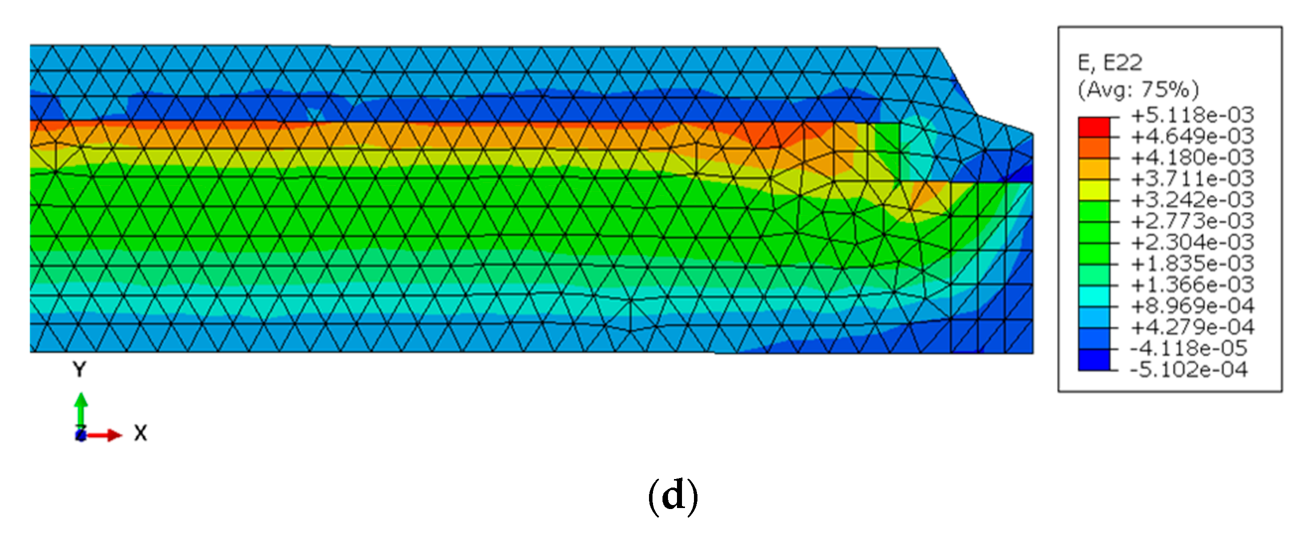
Figure 17. Isovalues of thermal strains at the interface: (a) reinforced panel, (b) fiberglass-reinforced panel, (c) insulated reinforced panel, (d) insulated fiberglass-reinforced panel.
Buildings 15 03664 g017aBuildings 15 03664 g017b
Table 1. Mechanical properties of the materials.
MaterialParameterValue
Concrete f c k [MPa]
ε c u [%]
E c m [MPa]
Poisson’s ratio (µ)
Specific heat capacity (C) [KJ/kg K]
Thermal conductivity (λ) [W/m K]
Coefficient of thermal expansion (α) [ K 1 ]
40.8
0.38
33 546
0.2
840
1.15
6 × 10 6
Timber (GL24h) f m , g , k [MPa]
f t , 0 , g , k [MPa]
f c , 0 , g , k [MPa]
f v , g , k [MPa]
E 0 , g , m e a n [MPa]
E 0 , g , 05 [MPa]
Poisson’s ratio (µ)
Specific heat capacity (C) [KJ/kg K]
Thermal conductivity (λ) [W/m K]
Coefficient of thermal expansion (α) [ K 1 ]
24 (h = 12%)
16.5
24
2.7
11 600
9400
0.3
1600
0.15
5.5 5
Resin f c [MPa]
f t [MPa]
ε t [%]
E t [MPa]
83 ± 4
32 ± 3
1.2 ± 0.2
3500 ± 500
h: Moisture content.
Table 2. Panels tested and test conditions.
TestsPanelsConditioningApplied
Temperature
(°C)
Loading
Process
Loading Duration (Hours)
Test 1FG-P1Without insulation6524Heating Cooling50
Test 2FG-P2-IInsulated7024Heating70
Test 3R-P3Without insulation6322Heating Cooling28
Test 4R-P4-IInsulated7026Heating70
Test 5R-P5Insulated6722Heating62
FG-P: Fiberglass-reinforced panel, R-P: Reinforced Panel (Standard panels).
Table 3. Gauges positioning summary.
SpecimensStrain Gauges Positioned at Mid-HeightStrain Gauges Positioned at the Edges

C2-Concrete
B3-Wood
B2-Wood
B1-Wood
G2-Concrete
b3-Wood
b2-Wood
b1-Wood
Panel 1
Panel 3
Panel 5
C3-Concrete
B5-Wood
B6-Wood
B7-Wood
Panel 2
Panel 4
G3-Concrete
b5-Wood
b6-Wood
b7-Wood
Table 4. Comparison Between Theoretical and Finite Element Values for ΔT = 50 °C.
Position (m)Shear Stress
(MPa)
Difference
AnalyticalFEAAnaly/FEA
(%)
10.520.7732
20.040.0520
3000
40.040.0520
60.520.7732
Table 5. Comparison Between Experimental and Finite Element Values for ΔT = 50 °C.
PanelCondition∆T-FEA
(°C)
∆T-Exp
(°C)
Difference
(EXP/FEA)
(%)
Reinforced panelUninsulated5242−19
Reinforced panelInsulated5646−17
Fiberglass-reinforced panelUninsulated5143−16
Fiberglass-reinforced panelInsulated5651−8
Disclaimer/Publisher’s Note: The statements, opinions and data contained in all publications are solely those of the individual author(s) and contributor(s) and not of MDPI and/or the editor(s). MDPI and/or the editor(s) disclaim responsibility for any injury to people or property resulting from any ideas, methods, instructions or products referred to in the content.