Abstract
LiDAR-based Simultaneous Localization and Mapping (SLAM) plays a key role in enabling inspection robots to achieve autonomous navigation. However, at installation construction sites of large-scale public buildings, existing methods often suffer from point-cloud drift, large z-axis errors, and inefficient loop closure detection, limiting their robustness and adaptability in complex environments. To address these issues, this paper proposes an improved algorithm, LeGO-LOAM-LPB (Large-scale Public Building), built upon the LeGO-LOAM framework. The method enhances feature quality through point-cloud preprocessing, stabilizes z-axis pose estimation by introducing ground-residual constraints, improves matching efficiency with an incremental k-d tree, and strengthens map consistency via a two-layer loop closure detection mechanism. Experiments conducted on a self-developed inspection robot platform in both simulated and real construction sites of large-scale public buildings demonstrate that LeGO-LOAM-LPB significantly improves positioning accuracy, reducing the root mean square error by 41.55% compared with the original algorithm. The results indicate that the proposed method offers a more precise and robust SLAM solution for safety inspection robots in construction environments and shows strong potential for engineering applications.
1. Introduction
In 2024, the total output value of China’s construction industry reached 32.65 trillion yuan, representing a 3.9% year-on-year increase. Nevertheless, the construction industry remains highly labor-intensive and exhibits relatively low levels of digitalization and informatization [1]. The sector continues to face persistent challenges, including low productivity, labor shortages, and significant safety risks. With the growing adoption of intelligent construction, the integration of artificial intelligence technologies into engineering processes has opened new avenues for advancing construction industrialization [2]. Construction robots, as key technological enablers of intelligent construction, have the potential to increase efficiency, reduce costs, and improve safety. These robots are increasingly applied across all stages of the building life cycle, including design, construction, operation and maintenance, and demolition [3]. During the construction phase, various sub-categories of construction robots have emerged [4], including bricklaying robots, 3D printing robots, steel-bar tying robots, tile-laying robots, spraying robots, material transportation robots, progress monitoring robots, and safety inspection robots. The construction industry ranks as the second-highest risk sector, following only the mining industry. In April 2024, China’s Ministry of Housing and Urban-Rural Development issued the Notice on Launching a Three-Year Action for Fundamental Improvement of Work Safety in Housing and Municipal Engineering, explicitly advocating the use of “smart construction sites + construction robots” as a breakthrough strategy to enhance intelligence, mechanization, and digitalization at construction sites, thereby fostering new productive forces for improving construction safety. In large-scale public building installation projects, where installation and decoration tasks often overlap, a three-dimensional construction space emerges in which multiple trades operate simultaneously. Such environments are characterized by high-risk factors, including complex procedures, frequent operations, abundant combustible materials, dense temporary facilities, and frequent hot-work activities (Figure 1). Against this backdrop, conducting systematic safety inspections at construction sites becomes particularly significant. A core prerequisite for autonomous robotic inspections is high-precision and robust SLAM technology [5], which ensures accurate pose estimation and environmental mapping to support path planning, real-time obstacle avoidance, and autonomous navigation.
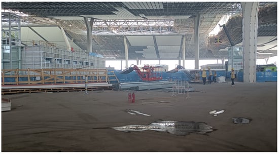
Figure 1.
The environment of the installation construction site of large-scale public buildings.
LiDAR (Light Detection and Ranging) and vision cameras are two mainstream sensor modalities employed in SLAM algorithms [6]. Compared with cameras, which are highly susceptible to illumination, reflection, and occlusion, LiDAR offers distinct advantages, including strong resistance to illumination interference, high ranging accuracy, and adaptability to complex working conditions [7]. Consequently, LiDAR has become the preferred sensing modality for SLAM systems in safety inspection robots at construction sites. LiDAR-based SLAM algorithms are commonly classified into 2D and 3D approaches according to the number of laser beams. Two-dimensional SLAM algorithms are well-suited for structured indoor environments with clear layouts and flat terrains [8]. However, in unstructured construction sites with severe dynamic disturbances, their performance is significantly constrained [9], making it difficult to achieve robust mapping in complex scenarios. LiDAR-based SLAM methods have been extensively applied in the domain of inspection robots, offering robust solutions for autonomous navigation and environment perception in complex scenarios. Chen et al. [10] proposed ISTA, a knowledge- and BIM-based automatic inspection framework that integrates ontology models of scenarios, tasks, and agents. This framework enables fully automated execution of facility inspection tasks and supports knowledge-driven decision-making. Huang et al. [11] introduced an enhanced FAST-LIO2 algorithm tailored for greenhouse environments by incorporating ground constraints and STD loop closure detection. Their multi-sensor fusion navigation system, combined with taught path planning and adaptive data acquisition strategies, achieved centimeter-level navigation accuracy under greenhouse conditions. In addition, Liu et al. [12] developed a LiDAR-based quadrotor UAV to address the challenges of slope inspection in dense vegetation environments. The proposed system demonstrated performance that significantly outperforms existing commercial UAV inspection solutions, thereby establishing a new benchmark for autonomous inspection in complex natural terrains. Therefore, 3D LiDAR SLAM algorithms have emerged as a key research focus for enhancing the intelligent perception capabilities of safety inspection robots at construction sites [13].
In recent years, substantial progress has been achieved in the field of 3D LiDAR SLAM. The LOAM algorithm [14] compensates for point cloud distortion under the assumption of uniform motion and performs inter-frame pose estimation by separately matching edge and planar features. LOAM is widely recognized as a seminal work in this field, inspiring numerous subsequent studies. Liu et al. [15] enhanced LOAM by incorporating SegMatch loop closure detection and ground constraints, thereby reducing drift errors and improving map accuracy. Wang et al. [16] proposed the global descriptor LiDAR-Iris, which achieves loop closure recognition via a binary feature map but suffers from long search times and high computational costs. ISC-LOAM [17], built upon the Fast-LOAM framework, constructs an intensity scan context (ISC) to enhance loop closure detection. F-LOAM [18] improves real-time performance while maintaining accuracy by employing non-iterative motion compensation, feature-weighted optimization, and lightweight map management. Deep-learning-based methods have also been explored for loop closure detection; however, they generally fail to meet real-time requirements in practical applications. The LeGO-LOAM algorithm proposed by Shan et al. [19] achieves lightweight and efficient mapping through ground extraction and ICP-based loop closure detection, making it suitable for ground-mobile robot platforms with limited resources.
Although these methods demonstrate strong performance on traffic-scene datasets such as KITTI [20], they encounter considerable challenges in the construction environments of large-scale public buildings. Large-scale public buildings are defined as single public buildings with a floor area exceeding 20,000 m2, characterized by highly complex construction processes and stringent quality requirements. First, these environments are distinguished by expansive spatial scales and strongly repetitive structural layouts. The alternation of long corridors and open spaces, together with the dense distribution of repetitive elements such as columns, doors, and windows, introduces spatial ambiguities in the point cloud, frequently resulting in front-end registration errors and loop closure detection failures. Furthermore, long-corridor scenarios typically lack sufficient observation constraints, giving rise to observation-degenerate environments. Second, the continuous presence of moving construction machinery, hoisted components, and workers traversing the site violates the static-environment assumption underlying most SLAM algorithms. This dynamic interference disrupts feature extraction and matching, thereby inducing localization drift and map misregistration. Finally, the diversity of materials commonly encountered in construction sites—including concrete, metal, glass, and plastic—exhibit markedly different reflection characteristics, which can cause laser signal attenuation or distortion and ultimately lead to feature mismatching and noise accumulation.
To address the aforementioned challenges, we extend the LeGO-LOAM algorithm, which is known for its computational efficiency, satisfactory system accuracy, and suitability for low-power embedded platforms. As a lightweight LiDAR SLAM framework, it offers an effective balance between real-time performance and deployment cost. Building upon this foundation, we propose LeGO-LOAM-LPB (LeGO-LOAM for Large-scale Public Buildings), with the objective of developing a robust and efficient positioning and mapping system tailored specifically to the installation and construction environments of large-scale public buildings. The proposed algorithm is designed to operate effectively under challenging conditions such as dynamic obstacles, complex layouts, and limited GNSS availability, thereby providing a reliable foundation for downstream tasks including path planning, autonomous navigation, and obstacle avoidance. The main contributions of this work are summarized as follows:
(1) Point cloud preprocessing: We introduce strategies such as outlier removal, ground point extraction, and dynamic object filtering to improve feature stability and representational capacity, thereby enhancing pose-estimation accuracy at the source.
(2) Front-end odometry: We add a ground-constraint term, employ an incremental kd-tree (ikd-tree) for efficient map construction, and adopt a two-layer loop closure mechanism to enhance system robustness.
(3) Experimental validation: We build an experimental platform for safety inspection robots, generate a simulation scene based on real construction drawings, and conduct large-scale data collection in combination with real construction sites. The mapping and positioning performance of the SLAM algorithm is systematically evaluated in both simulated and real installation construction environments of large-scale public buildings.
(4) Performance results: Experimental results demonstrate that the LeGO-LOAM-LPB algorithm achieves superior robustness and mapping accuracy in long-distance, large-scale, and complex installation construction environments, confirming its feasibility and practical value for construction engineering applications.
The remainder of this paper is organized as follows: Section 2 provides a systematic overview of the proposed SLAM method. Section 3 presents a detailed description of the LeGO-LOAM-LPB algorithm, including point cloud preprocessing, feature extraction, LiDAR odometry, map construction, and loop closure detection. Section 4 introduces the experimental platform for the inspection robot and conducts experimental validation and performance evaluation of the SLAM algorithm in both simulated environments based on large-scale public building construction sites and actual installation sites. Finally, Section 5 concludes the paper and discusses directions for future research.
2. System Overview
The LOAM framework pioneered a practical solution to the SLAM problem by decoupling it into two parallel optimization threads: a high-frequency odometry thread for real-time motion estimation and a low-frequency mapping thread for high-precision global optimization (Figure 2). However, its reliance on iterative scan matching and motion distortion correction introduces substantial computational overhead, limiting efficiency in large-scale applications. To address this limitation, F-LOAM adopts a non-iterative two-stage distortion compensation approach. The first stage assumes constant angular and linear velocities over short intervals to predict and preliminarily correct motion distortions, while the second stage refines distortion correction after pose optimization and updates the global map (Figure 3). This design significantly reduces computational cost while maintaining accuracy comparable to LOAM. Building on this progress, LeGO-LOAM further improves efficiency by segmenting the point cloud into ground and non-ground subsets and conducting feature extraction and matching separately. This selective processing strategy greatly reduces computational complexity without compromising localization accuracy, making it especially suitable for large-scale outdoor and semi-structured environments (Figure 4).
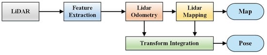
Figure 2.
System framework of the LOAM algorithm.
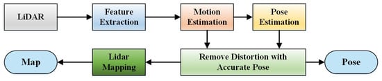
Figure 3.
System framework of the F-LOAM algorithm.
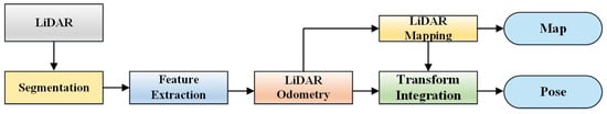
Figure 4.
System framework of the LeGO-LOAM algorithm.
The LeGO-LOAM-LPB algorithm proposed in this study comprises five modules: ground point cloud preprocessing, feature extraction, LiDAR odometry, LiDAR map construction, and loop closure detection. The overall system framework is illustrated in Figure 5. The specific steps are as follows:
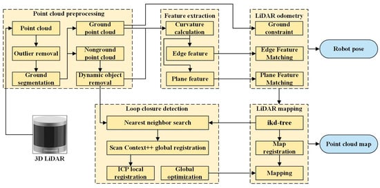
Figure 5.
System framework of the LeGO-LOAM-LPB algorithm.
(1) Point cloud preprocessing: After acquiring the LiDAR point cloud data, preprocessing is performed according to the environmental characteristics of installation construction sites of large-scale public buildings. This stage includes outlier removal, ground segmentation, and dynamic object removal, which improve feature quality at the source and enhance the robustness of odometry pose estimation.
(2) Feature extraction: Feature extraction is conducted on both ground and non-ground point clouds based on local curvature. High-curvature points are identified as edge features, corresponding to sharp geometric variations, whereas low-curvature points are classified as plane features, representing relatively flat surfaces.
(3) LiDAR odometry: Point cloud registration is performed using a two-step method. First, plane features are used to estimate z, pitch, and roll. Second, line features from the non-ground point cloud are used to estimate x, y, and yaw. Ground constraints are then applied to reduce z-axis estimation error. All constraints are integrated into a unified nonlinear optimization problem to obtain the optimal six-degree-of-freedom (6-DoF) pose transformation.
(4) LiDAR mapping: The Scan-to-Map feature-matching method is adopted, whereby edge and plane features extracted from the current frame are incrementally integrated into the global map. Using the ikd-tree data structure, which supports dynamic operations, only newly generated feature points are subject to insertion, deletion, or reinsertion, thereby enabling efficient map updates and maintenance.
(5) Loop closure detection: A two-layer loop closure mechanism combining Scan Context++ and ICP is constructed. Scan Context++ provides global perception, robustly proposes candidate frames under occlusion and viewpoint changes, and accelerates retrieval through a kd-tree. ICP then performs local fine registration based on the initial alignment and eliminates geometrically inconsistent mismatches. The combined results serve as constraints for graph optimization, from which the optimized pose estimation and point cloud map are generated.
3. Method
3.1. Data Preprocessing
3.1.1. Outlier Removal
At installation construction sites of large-scale public buildings, diverse materials such as concrete, metal, glass, plastic, and wood are commonly present (Figure 6). The surfaces of these materials exhibit heterogeneous reflectivity, which can result in weak or distorted echo signals and degrade the quality of LiDAR point clouds. When two adjacent planes are composed of different materials, their reflectivity differs markedly. Consequently, the reflection intensity varies substantially, even though the distances from the surrounding points to the LiDAR remain nearly identical [21]. In both cases, points exhibiting large variations in reflection intensity or distance are removed. Specifically, the removed points can be formulated as:
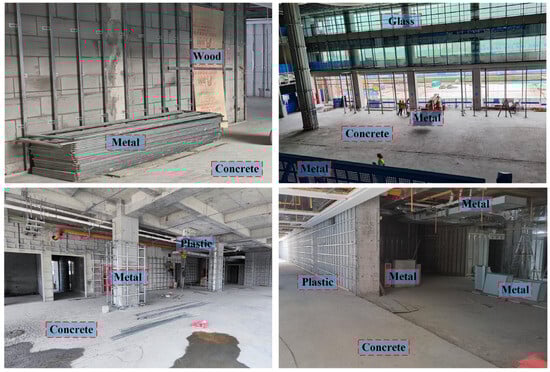
Figure 6.
Installation construction sites of large-scale public buildings with diverse materials, including concrete, metal, glass, plastic, and wood.
In Equations (1) and (2), the value range of j is (i − 5, i + 5).
By applying this method, outliers caused by variations in surface reflectivity and object distance can be effectively eliminated. Such outliers often introduce significant errors in point-cloud matching and motion estimation. Therefore, removing them prior to feature-point extraction not only enhances the reliability of feature selection but also improves the overall accuracy and robustness of the SLAM system. This process ensures that the extracted feature points are of higher quality, thereby directly contributing to more precise pose estimation.
3.1.2. Ground Segmentation
The ground at the installation construction site of large-scale public buildings is relatively flat. Effective segmentation of the ground point cloud from the 3D point cloud and subsequent plane fitting can, on the one hand, constrain the local map and the z-axis pose. On the other hand, because the inspection robot operates on the ground and the ground point cloud typically constitutes about one-third of the total data, ground segmentation significantly reduces the computational cost of subsequent feature extraction. Therefore, achieving fast and accurate ground point cloud segmentation has become a key challenge. In LeGO-LOAM, ground segmentation relies on curvature and height-difference features, which are easily influenced by uneven surfaces or noise, particularly in complex construction sites (e.g., with scaffolding or debris), leading to frequent mis-segmentation. To overcome this problem, this paper employs the Random Sample Consensus (RANSAC) [22] algorithm for ground segmentation. RANSAC effectively removes noise and irregular points through random sampling and consistency verification, thereby yielding more robust segmentation results under complex ground conditions. During LiDAR scanning, three points are randomly sampled from each frame of the point cloud to fit a plane.
According to the basic principle of RANSAC, three points are randomly sampled from each frame of the LiDAR point cloud to fit a candidate plane. The corresponding plane equation is expressed in Equation (3), where (a, b, c) denotes the normal vector of the plane, with its value range defined in Equation (4). Parameter d represents the distance from the LiDAR sensor to the plane, which is always greater than 0, thereby uniquely determining the plane. The specific segmentation steps are as follows:
(1) Step 1: Calculate the parameters of the plane equation. Three points P1 (x1, y1, z1), P2 (x2, y2, z2), and P3 (x3, y3, z3) are randomly selected from the point cloud P. These points define a plane S, whose parameters a, b, c and d can be computed using Equations (4) and (5).
(2) Step 2: Calculate the distance from points to the plane. For each point Pi (xi, yi, zi) in the point cloud P, the perpendicular distance di to the plane S is computed. If di is smaller than the pre-defined plane thickness, the point is classified as an inlier of plane S. A score is then assigned based on the number of inlier points, as expressed in Equation (6).
(3) Step 3: Iterate the sampling process. The above procedure is iterated across multiple random samplings, and the plane with the highest score is selected as the estimated ground plane.
(4) Step 4: Refine the ground plane. Based on the coarse ground segmentation obtained by RANSAC, a refined ground plane is fitted using the least-squares method, as given in Equation (7).
3.1.3. Dynamic Object Removal
At the installation construction sites of large-scale public buildings, various dynamic objects, including construction machinery, workers, and equipment, are frequently present. The motion of these dynamic objects can easily introduce errors into point-cloud matching, thereby degrading positioning accuracy. In addition, such motion induces further errors, resulting in significant drift during the mapping process.
For dynamic object removal, only non-ground point clouds are considered. This is because the ground serves as a common support surface that connects different objects, thereby interfering with object removal; moreover, it is inherently stationary and does not generate dynamic points. The proposed method simultaneously accounts for efficiency and robustness. Without relying on prior models or computationally expensive operations, the DBSCAN (Density-Based Spatial Clustering of Applications with Noise) algorithm is employed to cluster the point clouds [23]. Dynamic objects are distinguished from the static environment by analyzing the Euclidean distance between the centroids of clusters in consecutive frames. This approach eliminates the need for complex semantic segmentation or dedicated dynamic object detection algorithms. Thus, dynamic object removal can be achieved solely through clustering, while maintaining relatively low computational complexity.
3.2. Feature Extraction
In LiDAR odometry, scan-matching methods are typically employed to estimate the relative pose transformation between consecutive point clouds. These methods primarily encompass direct-matching and feature-based matching approaches. Direct-matching methods exhibit sensitivity to noise and suffer from low computational efficiency. Conversely, feature-based matching methods avoid processing the entire point cloud. Instead, they first extract distinctive feature points, subsequently achieving LiDAR odometry by minimizing point-to-line and point-to-plane distances. This approach offers superior computational efficiency and enhanced robustness, leading to its widespread adoption. Consequently, this paper utilizes extracted edge features and plane features to estimate the relative motion between consecutive frames. These features are distinguished based on curvature, with the selection criterion defined as follows:
where c denotes the curvature value, while ri and rj represent the Euclidean distances from points pi and pj in set S to the LiDAR sensor, respectively. A higher curvature value indicates a greater likelihood of the point being an edge feature, whereas a lower curvature value suggests a plane feature. During feature extraction, the point cloud is first sorted based on computed curvature values. Subsequently, points exhibiting the highest curvature values are selected as edge features, while those with the lowest curvature values are identified as plane features. This curated feature set provides the foundational data for subsequent LiDAR odometry calculations.
3.3. LiDAR Odometry
Following the acquisition of ground point clouds, edge features, and plane features, the inter-frame pose transformation is estimated by minimizing point-to-line and point-to-plane distances. LeGO-LOAM performs scan-matching between these features: current–frame edge features are matched against line segments (formed by two edge points) from the previous frame, while current–frame plane features are matched against planar patches (formed by three plane points), thereby constructing point-to-edge residuals (Eedge) and point-to-plane residuals (Eplane). However, for ground-based inspection robots, reliance solely on these constraints may induce significant matching errors. To enhance estimation accuracy, a ground constraint is incorporated by matching current–frame ground points to the ground plane (fitted from the previous frame’s point cloud), which yields a ground plane residual (Eground). These residuals are collectively minimized through nonlinear optimization as follows:
Here, T represents the robot’s 6-degree-of-freedom (6-DoF) pose. These constraints are collectively formulated within a unified nonlinear optimization framework to determine the optimal pose transformation T.
3.4. LiDAR Mapping
During LiDAR map construction, LeGO-LOAM utilizes a k-dimensional tree to enable efficient nearest neighbor search (NNS), matching feature points from newly scanned frames against historical point clouds in the local map. Construction sites of large-scale public buildings constitute dynamic environments where inspection robots require generation of extensive, long-term point cloud maps. However, traditional k-d trees are static structures that lack support for sliding-window deletion. As map scale increases, NNS performance deteriorates significantly. Moreover, each point insertion necessitates full tree reconstruction, leading to heightened matching errors, inefficient queries, and compromised real-time map updating capabilities. To address these limitations, our approach employs an ikd-tree for large-scale mapping. The ikd-tree performs incremental updates—inserting, deleting, or reinserting points without global reconstruction [24], thereby maintaining efficiency. Implementation details follow:
(1) Incremental Insertion: Upon acquiring new LiDAR data, the ikd-tree inserts points starting from the root node. It traverses the tree structure to determine optimal insertion positions and subsequently updates structural metadata.
(2) Lazy Deletion and Reinsertion: For dynamic objects or noise points, the ikd-tree employs a lazy deletion strategy, flagging points for deferred removal rather than immediate deletion. These points may be reinserted during subsequent update operations.
3.5. Loop Closure Detection
During each frame processing step, LeGO-LOAM identifies candidate frames with spatial overlap from historical frames. It employs the Iterative Closest Point (ICP) algorithm to register the current frame against historical frames, obtaining relative pose transformations. Successful matches are incorporated as loop closure edge constraints into the pose graph for global optimization, thereby mitigating cumulative errors and drift. However, this approach is limited to small-scale environments [25]. In the expansive, structurally repetitive, and complex settings characteristic of large-scale public building construction sites, the method incurs substantial computational overhead and is susceptible to both missed detections and false positives. To address these limitations, we propose a hierarchical loop closure detection framework:
(1) Primary Layer: Leveraging global structural features, the Scan Context++ descriptor reliably identifies candidate frames despite occlusions, viewpoint variations, and dynamic object interference [26]. Although ICP exhibits sensitivity to initial pose errors, the robust initialization provided by Scan Context++ ensures stable convergence.
(2) Secondary Layer: Scan Context++ generates an approximate relative pose estimate, which ICP subsequently refines through precise point cloud registration to ensure geometric consistency. Sole reliance on Scan Context++ may yield false positives due to environmental similarities (such as long straight corridors, atriums, and corridors); thus, ICP validation eliminates geometrically inconsistent loop closures.
Scan Context++ utilizes a k-d tree for efficient retrieval, while ICP operates exclusively on a limited candidate set, maintaining real-time performance. Furthermore, only non-ground points are processed for Scan Context++ generation to reduce computational burden. This synergistic integration combines Scan Context++’s robust global perception with ICP’s high-precision local constraints, yielding a loop closure detection framework that demonstrates enhanced stability, accuracy, and efficiency in complex environments.
4. Experimental Results and Analysis
4.1. Experimental Design
The experimental platform of the inspection robot and its principal components are illustrated in Figure 7. The inspection robot is powered by a 24 V lithium iron phosphate battery (30 Ah capacity). A motor drive controller regulates motor rotation speeds to enable precise attitude adjustment and motion control, achieving a maximum velocity of 3.0 m/s. The onboard computing platform an NVIDIA Jetson Xavier NX module, which communicates with the motor controller via a CAN (Controller Area Network) bus interface. Pulse–width modulation (PWM) signals govern both drive and steering motors. Sensor instrumentation includes a 16-line 3D LiDAR (RS-Helios-16P) and a nine-axis inertial measurement unit (IMU). The 3D LiDAR is mounted horizontally atop the robot at 0.88 m ground clearance, featuring a 360° horizontal field of view, 30° vertical field of view (±15°), 0.4° horizontal angular resolution, 2° vertical angular resolution, 10 Hz frame rate, ±2 cm accuracy, and 0.2–150 m effective range. The IMU operates at 200 Hz and is installed horizontally 0.15 m below the 3D LiDAR, maintaining precise spatial registration.
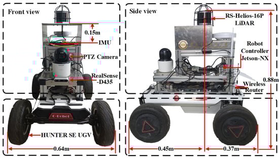
Figure 7.
Experimental platform for inspection robots.
The inspection robot’s onboard computing unit is a Jetson Xavier NX module integrating a 6-core NVIDIA Carmel ARM® v8.2 64-bit CPU, a 384-core NVIDIA Volta™ GPU, and 8 GB of LPDDR4x memory (manufacturer: Tuwei Information Technology (Shenzhen) Co., Ltd., China). Real-time connectivity to the ground control station is provided via a Wi-Fi local area network. The ground station uses an Acer laptop (manufacturer: Acer Smart (Chongqing) Co., Ltd., China) equipped with an 11th-generation Intel® Core™ i7-11800H CPU and an NVIDIA GeForce RTX 3060 GPU. Both the robot and the remote station run Ubuntu 18.04 LTS with ROS Melodic, utilizing the distributed multi-machine communication framework of ROS to support efficient data transmission and system coordination.
Conducting experiments at active large-scale public building construction sites presents significant challenges due to safety hazards and efficiency constraints. Many construction zones remain inaccessible, and repeated experimentation in identical areas proves impractical. Simulation environments offer a viable alternative to overcome robotics data collection limitations in real-world settings. These controlled environments enable safe, repeatable acquisition of consistent and reliable data—parameters frequently unattainable in actual construction sites. Consequently, this study employs a hybrid simulation-real-world validation approach to assess SLAM method accuracy.
4.2. Simulation Environment Experiment
4.2.1. Inspection Robot Simulation Model
Leveraging the inspection robot’s hardware specifications, we developed its URDF (Unified Robot Description Format) model using SolidWorks 2018 mechanical design software. The base URDF structure was optimized through xacro macros to reduce model complexity, particularly streamlining collision detection computations. Sensor models—including 3D LiDAR, camera, and IMU-were subsequently integrated into the robotic platform. Finally, Gazebo simulation tags, transmission mechanisms, and controller plugins were incorporated to complete the model. This simulated inspection robot enables comprehensive motion control and sensor perception capabilities. The model’s physical parameters match the experimental platform: maximum velocity (3.0 m/s), acceleration (3.0 m/s2), static friction coefficient (0.9), dynamic friction coefficient (0.6), and total mass (62 kg).
4.2.2. Construction Site Simulation Model
During the establishment of the simulation model for large-scale public building construction sites, to make the 3D environment model closer to the actual construction site, the construction CAD drawings are first processed by deleting semantic information of equipment specialties such as fire-fighting, lighting, power supply, and distribution in the drawings. Then, a BIM model is established based on the processed CAD drawings. Finally, the model is optimized through Blender to reduce the consumption of computational resources during Gazebo simulation. The optimized model is imported into the Gazebo simulation platform to form a simulation environment for large—scale public building construction sites. The establishment process of the simulation environment is shown in Figure 8. A BIM 3D model is established based on the CAD construction drawings of an under-construction outpatient building of a hospital in Xi’an. After being optimized by Blender, this model is imported into the Gazebo simulation platform to simulate the construction site environment. This hospital outpatient building is a typical large—scale public building. One standard floor is selected for modeling. The length of this standard floor is 292 m, the width is 142 m, the height is 6 m, and the area is 27,152 m2. The ground of this simulation environment is flat and contains walls, columns, long corridors, large—span spatial structures, and various hospital rooms with complex functions, as shown in Figure 8. It can be seen from the figure that this scene contains a large number of windowless long straight corridors, which are scarce in features, especially lacking linear features.
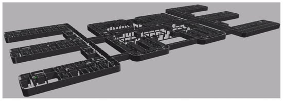
Figure 8.
Simulation environment of the installation construction site of large-scale public buildings.
During the data collection process of the inspection robot, the moving distance is 1293 m and the time is 1383 s. The robot passes not only a straight and narrow corridor (with parallel side walls at a fixed distance) but also an area with a more complex layout. In this area, the robot’s trajectory is an S-shaped curve. Throughout the process, the inspection robot does not pass the same position repeatedly, so loop closure detection cannot be used to reduce errors. This particularly tests the accuracy and stability of the LiDAR odometry.
4.3. Construction Site Experiment
Experiments were carried out at the installation construction site of an outpatient building of a hospital in Xi’an. This outpatient building is a typical large-scale public building. The main civil engineering structure has been topped out, and the focus of work is gradually shifting indoors. Multiple sub projects such as building water supply and drainage, heating, ventilation and air-conditioning, electrical building, and intelligent building are under construction simultaneously, with decoration and fit out works interspersed. Doors, windows, and curtain walls have not been installed yet, while ceiling and wall construction is in progress. Meanwhile, the construction of air-conditioning systems, lighting systems, firefighting facilities, mechanical and electrical equipment, and low-voltage electrical facilities is also being carried out in an interleaved manner. There are many dynamic construction workers, semi dynamic unstructured obstacles such as scaffolding, elevated work platform vehicles, and carts for transporting building materials at the construction site, as shown in Figure 9. Some areas of the hospital outpatient building construction site are under floor construction and are closed. Therefore, considering safety factors at the actual construction site, the moving speed and range of the inspection robot are less than those in the simulation environment. In this paper, data were collected on one standard floor of this large-scale public building. During the data collection process, the inspection robot experimental platform was manually controlled to move at the construction site for data collection using an Xbox360 controller (manufacturer: Qiaotou Kupeng Electronics Factory, Dongguan, China). The moving speed was set at 0.5 m/s, and the experimental time was 2067 s. Topic data from sensors such as LiDAR, IMU, and cameras were stored in Rosbag data packets.
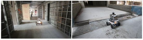
Figure 9.
Experiments in the complex environment of the installation construction site of large-scale public buildings.
4.4. Analysis of Experimental Results
4.4.1. Ground Point Cloud Segmentation
LeGO-LOAM-LPB enables more abundant and continuous extraction of ground points in the actual installation construction site of large-scale public buildings (as shown in Figure 10). These high quality ground points can not only serve as a candidate set for planar feature points but also provide stable and reliable geometric constraints for the non—linear optimization process of LiDAR odometry. Consequently, this effectively improves the accuracy of pose estimation and the overall robustness of the system.
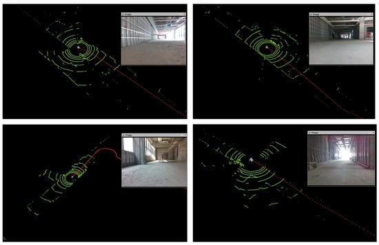
Figure 10.
Effect of ground point cloud segmentation.
4.4.2. Trajectory Estimation Results
Due to factors such as severe line of sight obstruction and difficulties in laying out measurement points at the installation construction site of large-scale public buildings, it is difficult to obtain the true movement trajectory of the inspection robot using a total station. Therefore, the dataset in the simulation environment of the large-scale public building construction site is used to evaluate the overall consistency between the trajectory output by the SLAM algorithm and the true trajectory. The evo_ape tool is used to evaluate the Absolute Pose Error (APE) of each SLAM algorithm based on the ground—truth trajectory. During the evaluation, both rotation and translation errors are considered, and the resulting absolute pose error is unitless. The specific evaluation indicators of APE include maximum error (Max), average error (Mean), median error (Median), root mean square error (Rmse), and standard deviation (Std), etc. The smaller the indicator data, the lower the error. The absolute pose errors of different SLAM algorithms are shown in Table 1. As can be seen from Table 1, in the simulation environment of the large-scale public building construction site, the proposed LeGO-LOAM-LPB algorithm has the lowest errors in all aspects. Compared with the original LeGO-LOAM before improvement, all indicators have significantly improved, with the root mean square error reduced by 41.55%.

Table 1.
Absolute pose error of the SLAM algorithm.
The comparison diagram between the estimated trajectory of the SLAM algorithm and the true trajectory is shown in Figure 11. As can be seen from Figure 8, when the inspection robot passes through the degraded environment of a long and narrow corridor without structural features, the z-axis error of the SLAM algorithm gradually increases. The reason is that the number of lines of the 16-line 3D LiDAR in the vertical direction is much less than that in the horizontal direction, and the vertical resolution is limited, resulting in a lack of effective geometric features and constraints in the vertical direction. However, the proposed LeGO-LOAM-LPB (green line) in this paper makes full use of the ground information for constraint, resulting in a smaller trajectory error and the highest degree of coincidence with the actual trajectory. Figure 12 shows the trajectory error evaluation results of the SLAM algorithm, mainly including the spatial error heatmap and the time series error distribution diagram. The spatial heatmap encodes the error magnitude by color based on the spatial position of the trajectory. The color gradually transitions from blue (small error) to green, yellow, and finally deep red (large error). The time series error distribution diagram reflects the trend of error change over time. The two form a corresponding relationship in the time and space dimensions to reflect the change law of the SLAM pose estimation accuracy throughout the operation process. The same conclusion can be drawn from Figure 12.
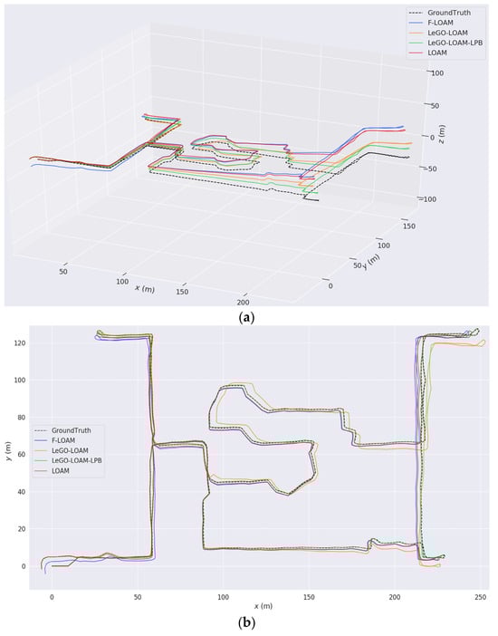
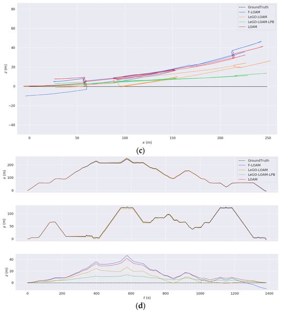
Figure 11.
Comparison diagram between the estimated trajectory and the true trajectory of the SLAM algorithm. (a) Three-dimensional trajectory diagram. (b) XY-plane trajectory diagram. (c) XZ-plane trajectory diagram. (d) Time-series diagrams of the trajectories in the directions of each coordinate axis changing with time.
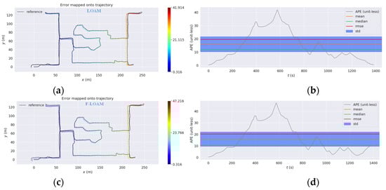
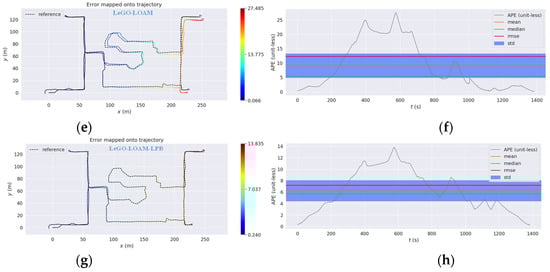
Figure 12.
Trajectory error plot of the SLAM algorithm. (a) LOAM spatial error heat map. (b) LOAM temporal error distribution plot. (c) F-LOAM spatial error heat map. (d) F-LOAM temporal error distribution plot. (e) LeGO-LOAM spatial error heat map. (f) LeGO-LOAM temporal error distribution plot. (g) LeGO-LOAM-LPB spatial error heat map. (h) LeGO-LOAM-LPB temporal error distribution plot.
4.4.3. Map Construction Results
During the operation of the inspection robot at the actual installation construction site of large-scale public buildings, the global point cloud map constructed based on the LeGO-LOAM-LPB algorithm is shown in Figure 13. This global map comprehensively reflects the large-scale structural features of the site, including walls and spatial structures. Figure 14 shows the actual photo of the local environment at the construction site and its corresponding local point cloud representation. It can be seen that whether it is the window frames, metal connectors on the walls, or the thermal insulation materials stacked on the ground, the point cloud map is highly consistent with the actual environment, without distortion or drift. It demonstrates good spatial continuity and structural restoration ability, providing reliable environmental model support for subsequent positioning, obstacle avoidance, and path planning.
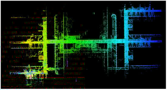
Figure 13.
Global point cloud map of the construction site.
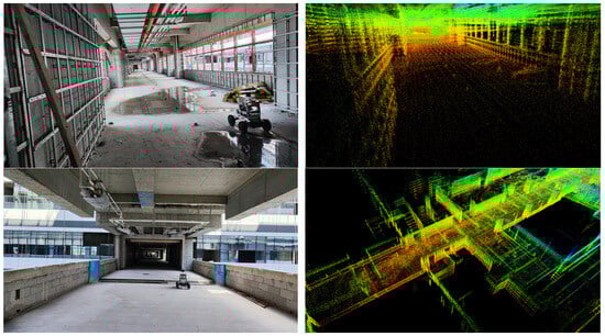
Figure 14.
Local environment of the construction site and its corresponding point cloud map.
5. Conclusions
This paper addresses the challenges of point cloud drift and low-efficiency loop closure detection faced by LiDAR-based SLAM in the installation construction sites of large-scale public buildings, and proposes a highly robust SLAM method for inspection tasks, termed LeGO-LOAM-LPB. Building upon the LeGO-LOAM framework, the proposed method systematically incorporates point cloud preprocessing, ground-constraint optimization, incremental k-d tree matching, and a two-layer loop closure detection mechanism. These enhancements significantly improve positioning accuracy and mapping consistency in complex environments. Field experiments demonstrate that the proposed method reduces the root-mean-square positioning error by 41.55% in typical construction scenarios, thereby enhancing adaptability in dynamically changing, structurally repetitive, and materially diverse environments. This work thus provides an efficient and practical solution for positioning and mapping inspection robots in unstructured large-scale public building installation sites.
Nevertheless, although the introduction of ground-residual constraints alleviates pose drift along the z-axis to some extent, the inherent limitations of single-modality LiDAR sensing make it difficult to fully suppress z-axis errors in long-distance or monotonous structural environments. Future research will focus on the development of advanced multi-sensor fusion strategies, particularly the integration of LiDAR and IMU data, to further enhance robustness and applicability in complex construction scenarios characterized by severe occlusions and drastic lighting variations. Furthermore, we plan to conduct extensive experiments on large-scale public buildings—defined as individual structures with a total floor area exceeding 20,000 m2—encompassing a variety of types and sizes. These efforts will serve to further evaluate and validate the SLAM algorithm’s performance across diverse realistic settings. In addition, an ultra-wideband (UWB) positioning system will be integrated to acquire high-precision ground-truth trajectories of inspection robots in indoor construction environments, thereby facilitating the construction of a more reliable and comprehensive dataset for validation purposes.
Author Contributions
Data curation, investigation, methodology, writing—original draft, writing—review and editing, C.F.; funding acquisition, project administration, supervision, J.Y.; data curation, investigation, software, J.L.; funding acquisition, project administration, Y.W.; data curation, investigation, software, B.W.; formal analysis, investigation, visualization, K.W. All authors have read and agreed to the published version of the manuscript.
Funding
This research was funded by the Key Research and Development Program of Shaanxi (2024GX-ZDCYL-02-04). XAUAT Engineering Technology Co., Ltd. technology research and development project (XAJD-YF24N008). Xi’an University of Architecture and Technology New Urbanization Youth Observation Project (2024GCJH21).
Data Availability Statement
Data will be made available on request.
Conflicts of Interest
Author Yonghua Wu was employed by the company XAUAT Engineering Technology Co., Ltd. The remaining authors declare that the research was conducted in the absence of any commercial or financial relationships that could be construed as a potential conflict of interest.
References
- Zhang, M.; Xu, R.; Wu, H.; Pan, J.; Luo, X. Human–Robot Collaboration for on-Site Construction. Autom. Constr. 2023, 150, 104812. [Google Scholar] [CrossRef]
- Chen, X.; Li, X.; Li, K.; Xu, K.; Luo, J.; Du, G.; Ge, Z.; He, C. Collaborative Optimization of Indoor Concrete Leveling Robot Path Based on Discrete Element Simulation. J. Build. Eng. 2025, 111, 113247. [Google Scholar] [CrossRef]
- Kim, S.; Peavy, M.; Huang, P.-C.; Kim, K. Development of BIM-Integrated Construction Robot Task Planning and Simulation System. Autom. Constr. 2021, 127, 103720. [Google Scholar] [CrossRef]
- Tsuruta, T.; Miura, K.; Miyaguchi, M. Mobile Robot for Marking Free Access Floors at Construction Sites. Autom. Constr. 2019, 107, 102912. [Google Scholar] [CrossRef]
- Zou, Q.; Sun, Q.; Chen, L.; Nie, B.; Li, Q. A Comparative Analysis of LiDAR SLAM-Based Indoor Navigation for Autonomous Vehicles. IEEE Trans. Intell. Transp. Syst. 2022, 23, 6907–6921. [Google Scholar] [CrossRef]
- Vassena, G.P.M.; Perfetti, L.; Comai, S.; Mastrolembo Ventura, S.; Ciribini, A.L.C. Construction Progress Monitoring through the Integration of 4D BIM and SLAM-Based Mapping Devices. Buildings 2023, 13, 2488. [Google Scholar] [CrossRef]
- Ibrahimkhil, M.H.; Shen, X.; Barati, K.; Wang, C.C. Dynamic Progress Monitoring of Masonry Construction through Mobile SLAM Mapping and As-Built Modeling. Buildings 2023, 13, 930. [Google Scholar] [CrossRef]
- Brosque, C.; Hawkins, J.T.; Dong, T.; Örn, J.; Fischer, M. Comparison of On-Site and off-Site Robot Solutions to the Traditional Framing and Drywall Installation Tasks. Constr. Robot. 2023, 7, 19–39. [Google Scholar] [CrossRef]
- Wang, X.; Ding, D.; Fu, W. A Robust Lidar-Inertial Localization System Based on Outlier Removal. In Proceedings of the 2021 China Automation Congress (CAC), Beijing, China, 22–24 October 2021; pp. 2420–2425. [Google Scholar]
- Chen, J.; Lu, W.; Fu, Y.; Dong, Z. Automated Facility Inspection Using Robotics and BIM: A Knowledge-Driven Approach. Adv. Eng. Inform. 2023, 55, 101838. [Google Scholar] [CrossRef]
- Huang, Z.; Yang, N.; Cao, R.; Li, Z.; He, Y.; Feng, X. Autonomous Navigation System in Various Greenhouse Scenarios Based on Improved FAST-LIO2. Comput. Electron. Agric. 2025, 234, 110279. [Google Scholar] [CrossRef]
- Liu, W.; Ren, Y.; Guo, R.; Kong, V.W.W.; Hung, A.S.P.; Zhu, F.; Cai, Y.; Wu, H.; Zou, Y.; Zhang, F. Slope Inspection under Dense Vegetation Using LiDAR-Based Quadrotors. Nat. Commun. 2025, 16, 7411. [Google Scholar] [CrossRef]
- Kaya, Y.F.; Orr, L.; Kocer, B.B.; Pawar, V.; Stuart-Smith, R.; Kovač, M. Aerial Additive Manufacturing: Toward on-Site Building Construction with Aerial Robots. Sci. Robot. 2025, 10, eado6251. [Google Scholar] [CrossRef]
- Zhang, J.; Singh, S. Low-Drift and Real-Time Lidar Odometry and Mapping. Auton. Robot. 2017, 41, 401–416. [Google Scholar] [CrossRef]
- Liu, X.; Zhang, L.; Qin, S.; Tian, D.; Ouyang, S.; Chen, C. Optimized LOAM Using Ground Plane Constraints and SegMatch-Based Loop Detection. Sensors 2019, 19, 5419. [Google Scholar] [CrossRef] [PubMed]
- Wang, Y.; Sun, Z.; Xu, C.-Z.; Sarma, S.E.; Yang, J.; Kong, H. LiDAR Iris for Loop-Closure Detection. In Proceedings of the 2020 IEEE/RSJ International Conference on Intelligent Robots and Systems (IROS), Las Vegas, NV, USA, 25–29 October 2020; pp. 5769–5775. [Google Scholar]
- Wang, H.; Wang, C.; Xie, L. Intensity Scan Context: Coding Intensity and Geometry Relations for Loop Closure Detection. In Proceedings of the 2020 IEEE International Conference on Robotics and Automation (ICRA), Paris, France, 31 May–31 August 2020; pp. 2095–2101. [Google Scholar]
- Wang, H.; Wang, C.; Chen, C.-L.; Xie, L. F-LOAM: Fast LiDAR Odometry and Mapping. In Proceedings of the 2021 IEEE/RSJ International Conference on Intelligent Robots and Systems (IROS), Prague, Czech Republic, 27 September–1 October 2021; pp. 4390–4396. [Google Scholar]
- Shan, T.; Englot, B. LeGO-LOAM: Lightweight and Ground-Optimized Lidar Odometry and Mapping on Variable Terrain. In Proceedings of the 2018 IEEE/RSJ International Conference on Intelligent Robots and Systems (IROS), Madrid, Spain, 1–5 October 2018; pp. 4758–4765. [Google Scholar]
- Geiger, A.; Lenz, P.; Stiller, C.; Urtasun, R. Vision Meets Robotics: The KITTI Dataset. Int. J. Robot. Res. 2013, 32, 1231–1237. [Google Scholar] [CrossRef]
- Wang, Z.; Liu, G. Improved LeGO-LOAM Method Based on Outlier Points Elimination. Measurement 2023, 214, 112767. [Google Scholar] [CrossRef]
- Qian, X.; Ye, C. NCC-RANSAC: A Fast Plane Extraction Method for 3-D Range Data Segmentation. IEEE Trans. Cybern. 2014, 44, 2771–2783. [Google Scholar] [CrossRef] [PubMed]
- Pierzchała, M.; Giguère, P.; Astrup, R. Mapping Forests Using an Unmanned Ground Vehicle with 3D LiDAR and Graph-SLAM. Comput. Electron. Agric. 2018, 145, 217–225. [Google Scholar] [CrossRef]
- Cai, Y.; Xu, W.; Zhang, F. Ikd-Tree: An Incremental K-D Tree for Robotic Applications 2021. arXiv 2021, arXiv:2102.10808. [Google Scholar]
- Tang, J.; Zhang, X.; Zou, Y.; Li, Y.; Du, G. A High-Precision LiDAR-Inertial Odometry via Kalman Filter and Factor Graph Optimization. IEEE Sens. J. 2023, 23, 11218–11231. [Google Scholar] [CrossRef]
- Kim, G.; Choi, S.; Kim, A. Scan Context++: Structural Place Recognition Robust to Rotation and Lateral Variations in Urban Environments. IEEE Trans. Robot. 2022, 38, 1856–1874. [Google Scholar] [CrossRef]
Disclaimer/Publisher’s Note: The statements, opinions and data contained in all publications are solely those of the individual author(s) and contributor(s) and not of MDPI and/or the editor(s). MDPI and/or the editor(s) disclaim responsibility for any injury to people or property resulting from any ideas, methods, instructions or products referred to in the content. |
© 2025 by the authors. Licensee MDPI, Basel, Switzerland. This article is an open access article distributed under the terms and conditions of the Creative Commons Attribution (CC BY) license (https://creativecommons.org/licenses/by/4.0/).