Abstract
Dams are currently confronted with severe risks from frequent extreme climates and expanding aging deterioration, with traditional mitigation measures struggling to balance efficient prevention/control and long-term management. As an innovative solution, fiber-reinforced polymer (FRP) composites support improved dam safety governance. To address the lack of systematic integration in existing dam-related studies, this paper promotes the development of an FRP in the dam field by comprehensively analyzing and summarizing the material properties, interfacial bonding properties of the FRP, as well as the flexural and compressive characteristics of FRP bar–concrete members and FRP sheet–concrete members while systematically organizing their practical engineering application cases. It also explores the FRP’s potential in hydraulic structures and suggests its wider application therein based on the FRP’s superior properties.
1. Introduction
Dams, as core infrastructure for ensuring water resource allocation, flood control, and power generation, play a crucial role not only in the sustainable development of regional economies but also in safeguarding social and public security. In recent years, the frequent occurrence of extreme weather events has become an undeniable reality [1], with natural disasters such as super-standard floods, earthquakes, and droughts increasingly threatening the safety of dams. Meanwhile, with the prolonged service life of dams, issues related to the aging and degradation of many existing dams are gradually becoming more apparent [2]. Particularly in some early-built dams, due to limitations in design standards, construction technologies, and material properties at the time of construction, the problem of aging and degradation is more pronounced, exacerbating the risk to dam safety. Moreover, as society continues to place greater emphasis on public safety, the regulatory authorities overseeing dams have imposed more stringent safety requirements [3], particularly regarding the effective monitoring and mitigation of safety risks during the operation and maintenance phase. Therefore, the safety of dams is facing unprecedented challenges.
During the long-term operation of dam structures, there exist specific aging problems, including spalling damage of the concrete surface layer caused by carbonation and freeze–thaw cycles, the occurrence of temperature cracks and load-induced cracks in the dam body, corrosion of internal steel bars in concrete dams due to electrochemical reactions, the need for strengthening the anti-seepage curtain of the dam foundation, and the requirement for improving the erosion and abrasion resistance of spillways. Appropriate materials and technologies are required for treatment to ensure the structural safety and long-term operation of dams.
According to data from authoritative organizations such as the International Commission on Large Dams (ICOLD), structural aging and material degradation account for 65% of dam safety risks over the past decade. In aging dams, risks such as surface cracking induced by the expansion of rusted internal steel reinforcement in concrete, as well as concrete deterioration in spillways, are common phenomena. However, traditional reinforcement and repair materials represented by reinforced concrete, which are heavy and have poor corrosion resistance, are prone to rust in humid and chemically corrosive environments [4]. This condition leads to cracking of dam concrete, making it difficult to ensure long-term safety. Under such circumstances, fiber-reinforced polymer (FRP) composites, owing to their unique mechanical properties and superior durability, offer a new paradigm for dam safety risk mitigation [5]. FRP is composed of reinforcing fibers, matrix materials, and auxiliary components, and its performance is determined by the interaction of these three [6]. Reinforcing fibers (such as carbon fibers, glass fibers, aramid fibers, etc.) act as the structural skeleton, characterized by high aspect ratios and pronounced anisotropy, which govern load transfer and directional strength. Matrix materials (thermosetting or thermoplastic resins such as epoxy resin and polyester resin) absorb energy through plastic deformation, alleviate stress concentration caused by fiber fracture, protect fibers from environmental erosion through interface bonding, and coordinate load distribution. Auxiliary components (coupling agents, nanofillers) strengthen interface bonding and optimize matrix performance. The tensile strength of FRP composites is 3–10 times that of steel, and the elastic modulus reaches 200–700 GPa (for carbon fibers). However, their shear strength is relatively low, typically 5–20% of tensile strength, necessitating advanced manufacturing techniques such as 3D weaving for improvement. Both the absolute value and relative ratio of shear strength are low, exhibiting the characteristic of “high tensile strength but low shear strength”; the anisotropy is significant, and when the shear direction forms a large angle with the fiber axis, the shear force transmission relies on the matrix and interface with low shear resistance, which is prone to brittle fracture; moreover, environmental factors such as humidity and acid-alkali erosion can further exacerbate the degradation of its shear performance.
Future enhancements may involve fiber hybridization, ply optimization, and nano-modification. Overall, FRP composites exhibit advantageous properties including lightweight, high strength, corrosion resistance, fatigue resistance, and low coefficient of thermal expansion, enabling effective applications in dam structural reinforcement, seepage control, seismic upgrading, and structural health monitoring. In structural reinforcement [7], externally bonded or wrapped FRP systems enhance load-bearing capacity while inhibiting crack propagation and seepage deterioration. FRP seepage barriers leverage corrosion resistance and conformability to form effective impermeable layers on complex dam surfaces, addressing adhesion failures common in conventional materials. For seismic regions, FRP wrapping of critical dam components [8] improves earthquake resistance without significantly increasing self-weight. Combining FRP materials with sensor technology [9], embedding sensors to monitor dam structural parameters in real-time can timely capture abnormalities and issue early warnings, realizing early detection and early treatment of safety risks. While challenges remain in shear performance optimization and high-temperature applicability, FRP’s superior corrosion resistance and adaptability for complex structural repairs demonstrate significant potential as a traditional material substitute. Further investigation into FRP’s mechanical behavior, long-term durability, and engineering applicability will refine dam reinforcement strategies, ultimately enhancing dam safety, durability, and management efficacy.
The innovation of this study lies in discussing the feasibility of applying FRP to dam risk mitigation measures, whereas other existing studies still focus on the discussion of the basic performance of components. Based on the mechanical properties and experimental performance of FRP composites, combined with practical engineering cases, this paper deeply explores their potential application and practical value in dam safety risk mitigation, provides a new technical approach for dam safety risk management, aiming to offer technical support for technological innovation and safety enhancement in the field of hydraulic engineering.
2. Research Progress on FRP Bar–Concrete Members
2.1. Material Properties of FRP Bars
To comprehensively leverage the excellent properties of FRP bars, ordinary steel bars can be replaced with FRP bars, which fundamentally solves the problem of steel corrosion in concrete structures under harsh environmental conditions. This approach is primarily applied to the reinforcement of non-load-bearing components, improving their crack resistance and seismic capacity through implantation or tensioning techniques. Extensive experimental research and summarization have been conducted on FRP bars by researchers and engineers both domestically and internationally. Studies have shown [10] that the type, content, cross-sectional shape of fibers and the manufacturing process all influence the mechanical properties of FRP bars to a certain extent. Currently, the commonly used FRP materials in engineering include Carbon Fiber Reinforced Polymer (CFRP), Aramid Fiber Reinforced Polymer (AFRP), Glass Fiber Reinforced Polymer (GFRP), and Basalt Fiber Reinforced Polymer (BFRP) independently developed in China. It has been found that the mechanical properties of FRP bars are improved correspondingly with the gradual increase in fiber content. The fiber content of common FRP bars or rods is typically between 70% and 80%, while their volume content is approximately between 60% and 65%. The surface forms of FRP bars include smooth round, threaded, rectangular and I-shaped. FRP bars also include the common strand form, with their outer diameter ranging from 3 mm to 40 mm. The physical and mechanical properties of FRP bars vary due to factors such as processing technology, methods, fiber types and content. Therefore, China’s “Technical Specification for Application of Fiber Reinforced Polymer in Building Engineering” [11] (GB50608-2010) provides reference values for four commonly used types of FRP bars, as shown in Table 1.

Table 1.
Mechanical properties of FRP bars.
The tensile strength of FRP bars is generally superior to that of ordinary steel bars on the same specification, being 20% higher, and they also exhibit excellent fatigue resistance. Meanwhile, they are relatively lightweight, with a density merely 25% that of steel bars, ranging from 1.5 to 1.9 g/cm3. They also possess strong corrosion resistance, capable of withstanding corrosion from chemical substances such as acids and alkalis, and demonstrate the performance of resisting chloride ions and low pH solutions, particularly showing enhanced resistance to carbides and chlorides [12]. Additionally, as non-magnetic materials, FRP bars have high magnetic permeability and do not require demagnetization treatment in concrete members. Their elastic modulus is relatively low, approximately 24.3% that of steel bars, enabling them to withstand large deformations. Consequently, FRP-reinforced beams often undergo greater deflection deformation than ordinary steel-reinforced beams. However, the shear resistance of FRP bars is relatively weak [13]. Due to their anisotropic characteristics, their transverse shear performance is significantly inferior to their longitudinal tensile performance, with research indicating that their shear strength is typically only about 10% of their tensile strength. In a chemical corrosion environment (salt solution), the influence on the tensile strength of BFRP is significantly weaker than that on GFRP. Under the action of wet-dry cycles, the tensile strength of CFRP changes little, while that of GFRP is greatly affected. Both CFRP and GFRP have their elongation rates affected, but the impact on the latter is more significant. The elastic moduli of CFRP and GFRP are not affected.
2.2. Interfacial Bond Properties Between FRP Bar and Concrete
2.2.1. Failure Modes of the FRP Bar–Concrete Interface
Due to the wider use of GFRP bars than the other types, e.g., AFRP, CFRP, or BFRP, the following discussion will be mainly focused on the performance of concrete members embedded with GFRP bars. The bond strength between FRP bars and concrete primarily consists of three components [14]: chemical adhesion formed between concrete and the surface of FRP bars, mechanical interlock generated between the ribs on the surface of FRP bars and the surrounding concrete, and frictional force induced by the relative slip between FRP bars and concrete. The failure modes of FRP bar–concrete structures mainly include three types [15,16], and several typical failure morphologies are illustrated in Figure 1. Among these, FRP bar pull-out failure is relatively common, where part of the concrete at the bonding interface between FRP bars and concrete becomes detached, with no cracks appearing on the concrete surface and several concrete fragments adhering to the FRP bars, thereby weakening the mechanical interaction and frictional resistance at the FRP-concrete interface [17]. In the case of concrete splitting failure, the portion of the specimen spalls off with a distinct cracking sound, and cracks propagate significantly, leading to extensive cracking and spalling of the concrete before the FRP bar is pulled out [18]. Bar splitting failure typically involves longitudinal splitting at the load of the FRP bar, and during failure, the bonded section of the FRP bar exhibits rib yarn peeling [15]. In contrast, bar rupture failure occurs in concrete with high strength, characterized by sudden rupture or cracking of the FRP bar at the loaded, with slight wear on the surface of the bonding interface, which may be caused by stress concentration in the FRP bar.

Figure 1.
Several typical failure modes of specimens [15,16]: (a) Pull-out failure; (b) Splitting failure; (c) Fracture failure of FRP bars.
2.2.2. Influencing Factors of Bond Performance
- (1)
- Surface shape and diameter of FRP bars
FRP bars exhibit diverse surface characteristics due to their wide range of application scenarios, and their bond performance with concrete demonstrates significant differences owing to varying geometric properties. Based on existing research, Wang et al. [19] conducted pull-out tests on 407 FRP bars with different surface types, including sand-coated, spirally wrapped, ribbed, and indented surfaces. The results indicated that surface treatment significantly influences the bond performance between FRP bars and concrete, and a new model is proposed, which can accurately evaluate the influence of surface characteristics on the bond behavior. Solyom et al. [20] carried out 200 traditional pull-out tests and 38 direct pull-out tests, revealing that bond strength, bond stress-slip relationship, representative bond stress, and failure modes all exhibit significant differences with varying surface characteristics. For specific surface categories, such as sand-coated and threaded ones, the bond strength fluctuates within a wide range.
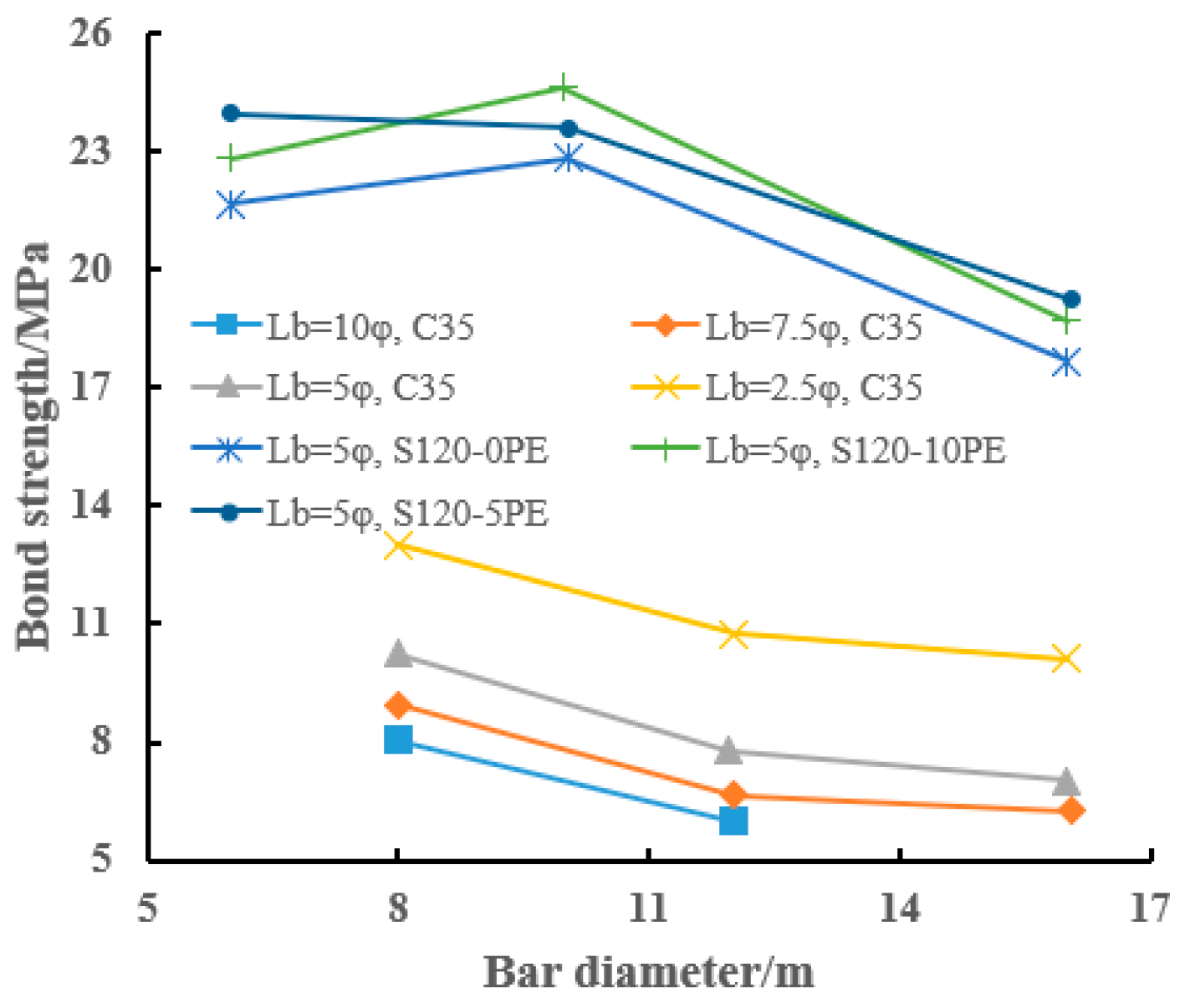
The diameter of FRP bars also significantly influences the interfacial bond performance. Some scholars [21,22,23] have pointed out that when the diameter of FRP bars ranges from 7 mm to 29 mm, the bond strength exhibits a negative correlation with the bar diameter. Shen et al. [24] indicated through pull-out test results that when the bar diameter increases from 10 mm to 14 mm and 20 mm, the bond strength decreases by 8.1% and 30.1%, respectively, while the slip corresponding to the bond strength increases by 23.8% and 38.7%, respectively. Generally, such changes are closely related to chemical forces and material properties. For a given embedment length, the bond strength decreases with the increase in FRP bar diameter [25], as shown in Figure 2. The bond strengths of specimens with diameters of 6 mm and 10 mm are similar; in particular, when the bar diameter increases from 10 mm to 16 mm, the bond strength decreases significantly. For example, under fiber volume fractions of 0%, 5%, and 10%, the bond strength decreases by 22.2%, 20.3%, and 23.4%, respectively [26]. The primary reason for the significant impact of FRP bar diameter on bond performance is that as the bar diameter increases, although the absolute bond area increases, the bond area per unit volume decreases accordingly, directly leading to a decline in bond performance. Additionally, due to the Poisson’s ratio effect, a larger Poisson’s ratio causes the bar diameter to reduce during the pull-out process, thereby decreasing the contact area between the bar and the surrounding concrete, reducing friction, and ultimately resulting in a decrease in bond strength [27].
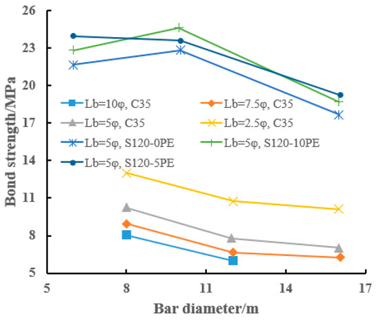
Figure 2.
Influence of bar diameter on bond strength [18].
- (2)
- Concrete strength and cover thickness
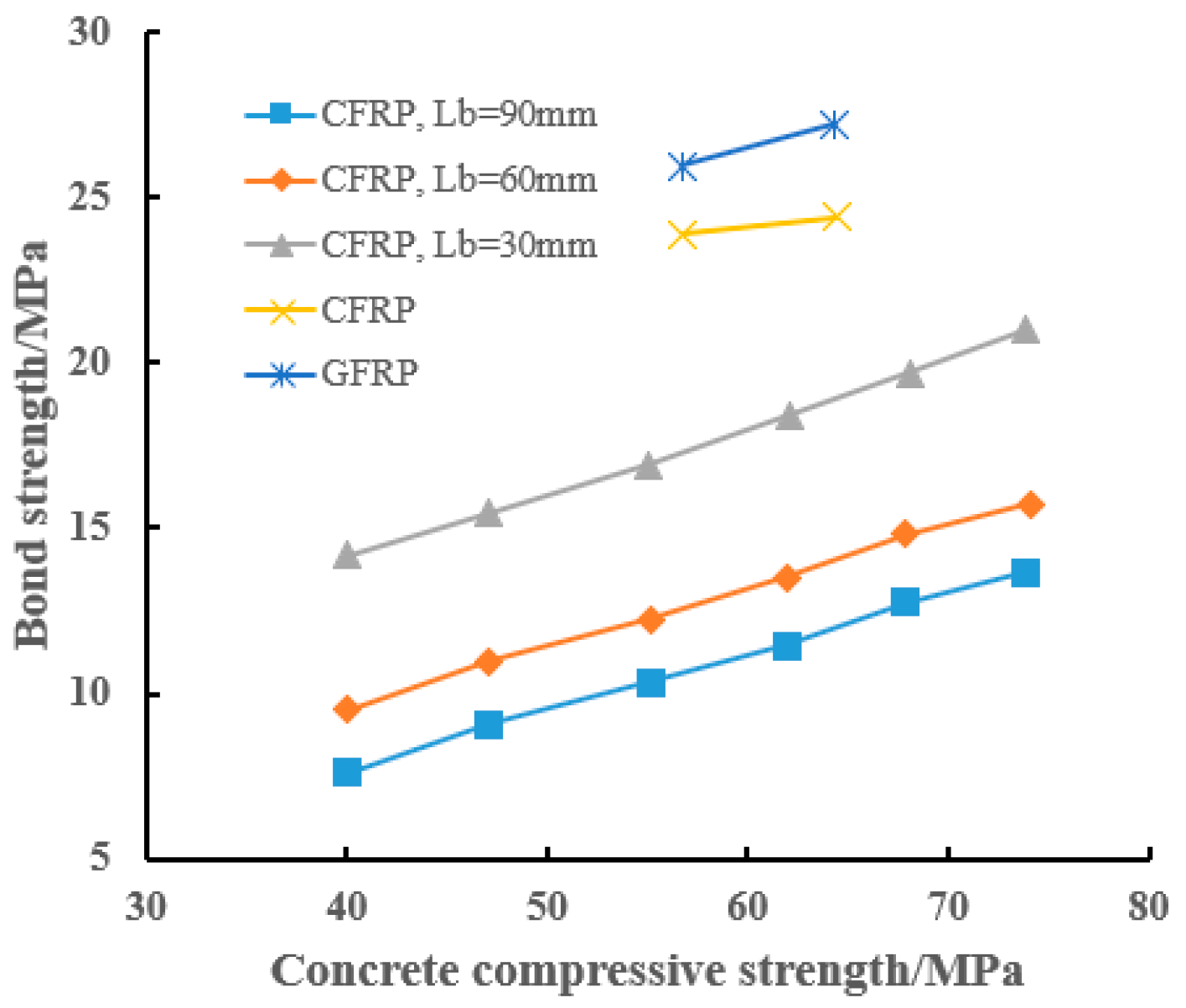
The compressive strength of the concrete matrix can alter the failure mode of FRP bars, while the bond strength increases with the enhancement of compressive strength. Concrete with higher strength exhibits stronger chemical adhesion with FRP bars and better mechanical interlocking at the interface. Therefore, the bond performance is directly related to the compressive strength of concrete [28], and the relationship between them is shown in Figure 3. By observing the failure modes of pull-out specimens, Zhang et al. [18] found that for seawater and sea-sand concrete, the bond strength increases with the increase in concrete compressive strength; however, when the compressive strength exceeded 50 MPa, the failure modes of the specimens were mainly cracking or fracture of FRP bars. Su et al. [29] compared the pull-out tests results of concrete specimens with two strength grades and found that, given a specific FRP bar material, the bond strength increased with the improvement in concrete strength and was unaffected by the bond length. Zemour et al. [30] conducted tensile tests on FRP bars with a diameter of 13 mm embedded in concrete, and found that the type of concrete has little influence on the bond strength, which increases with the rise in concrete strength. Although increasing the concrete strength can enhance the bond performance, the improvement effect is quitely limited; when the concrete strength increases by 46%, the bond strength only increases by an average of 4.5%. Moreover, under high strength conditions, pull-out failure mostly occurs at the interface between the sand-coated surface layer and the inner layer of FRP bars, resulting in the peeling of the sand-coated layer. Additionally, excessively high concrete strength may lead to concrete drying shrinkage, which in turn causes the failure mode to transform from normal pull-out failure to splitting failure, thereby reducing the bond strength [31].
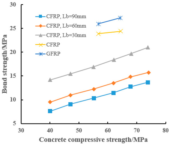
Figure 3.
Influence of concrete compressive strength on bond strength [18].
- (3)
- Fiber types of FRP bars
Due to the differences in material properties among various fiber types, FRP bars exhibit variations in mechanical properties, durability, and bond performance with concrete. By comparing the bond performance of different FRP bars, Achillides et al. [21] found that the bond strength of FRP bars can reach 72% of that of traditional steel bars. Wang et al. [16] studied the influence of fiber types on the average bond strength, demonstrating that CFRP bars exhibit superior bond strength compared to BFRP and GFRP bars. However, due to differences in test materials and methods, there are discrepancies in the conclusions regarding the bond strength of BFRP and GFRP bars. Tong [28] argued that in seawater and sea-sand concrete, the bond strength of BFRP bars is better than that of GFRP bars, which may be attributed to the differences in surface roughness and mechanical properties of the bars. Conversely, Wang et al. [32] discovered through experiments that the durability of BFRP bars exposed to seawater environments is lower than that of GFRP bars. These findings indicate that there is no unified conclusion on the influence of fiber types in FRP bars on bond performance. Different fiber types in FRP bars significantly affect their structural stiffness, which can alter the ascending portion of the bond-slip curve and thus cause changes in bond strength [33]. Therefore, further in-depth research is required to elucidate the influence mechanism of fiber type in FRP bars on the bond performance between the bars and concrete.
In summary, from the perspective of the inherent properties of the FRP bars, the surface treatment type of the FRP bars has a more pronounced impact on the interfacial bond performance, whereas the fiber type and diameter of the FRP bars exert relatively less obvious influence. When considering the effect of concrete compressive strength, the bond strength increases correspondingly with the improvement of the compressive strength of the concrete matrix, but this growth trend is relatively limited in high-strength concrete. In studies on the effect of fiber type on BFRP/GFRP bar–concrete bond strength, conclusions remain inconsistent, primarily due to cross-interference of four variables: first, inherent property trade-offs between the two FRP bar fibers (BFRP has high modulus but vulnerable interface, while GFRP has stable interface but low modulus); second, non-standardized test designs with inconsistent key parameters (e.g., concrete strength, bar surface treatment) causing discrete results; third, insufficient long-term environmental performance comparison data and varied aging protocols; fourth, divergent bond performance evaluation dimensions (focus on peak strength or ductility) without a unified benchmark. Based on the results of FRP bar pull-out tests, Peng [34] integrated experimental observations with an analytical framework to propose a modified bond strength model for carbon fiber-reinforced polymer (CFRP) bars and geopolymer mortar. This model enables the theoretical prediction of the bond strength between FRP bars and concrete under relevant conditions and provides effective guidance for design practice.
Future research should comprehensively consider the influencing factors of the bond performance between FRP bars and concrete, such as the rib height, rib spacing, surface roughness, fiber type, and diameter of the bars, as well as the compressive strength, cover thickness, and age of concrete, to establish an accurate prediction model. The key research on prediction models for the bond performance between FRP bars and concrete in dam engineering is inadequate in the following aspects: Most models are based on simple mechanical tests and cannot simulate the complex stress coupling in dams; long-term performance models have not fully incorporated the bond degradation laws induced by the environment and loads during the service period; there is a lack of quantitative analysis on the coupling effect of multiple influencing factors; the bond-slip constitutive relation is insufficient in describing scenarios such as the combination of FRP bars and UHPC and the descending segment of the curve; moreover, the variability of bond strength is not considered, and there is a lack of guarantee rate calculation models that meet the high reliability requirements of dams. Additionally, attention should be paid to the impact of complex environments such as high temperature, high humidity, and corrosion on bond performance, and the long-term durability of FRP bar-reinforced concrete structures should be evaluated.
2.3. Flexural Behavior of FRP Bar-Reinforced Concrete Beams
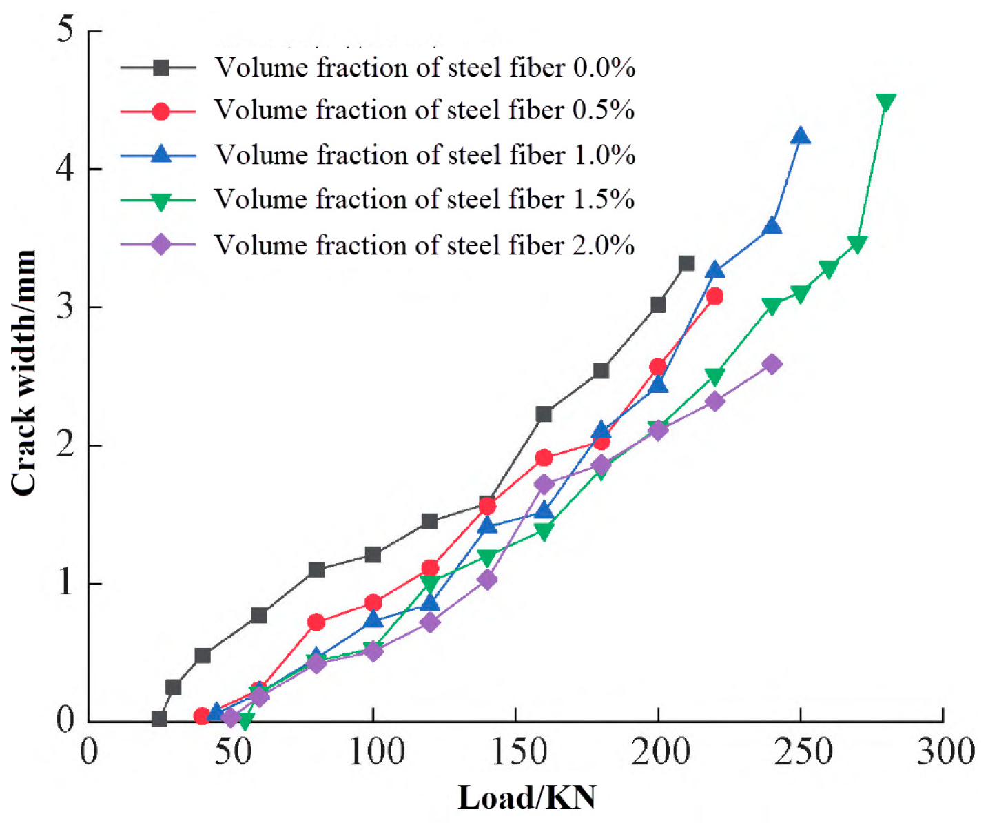
During the loading process, the low elasticity of FRP bars often leads to excessive deformation and crack width of beam members, with brittle failure being the predominant failure mode. Shen [35] found that the failure of FRP bar-reinforced concrete beams also undergoes three distinct loading stages: elastic behavior, cracked behavior, and ultimate failure. Elgabbas et al. [36] found that compared with ordinary reinforced concrete beams, FRP bar-reinforced beams exhibit more rapid crack development and wider crack widths, and the axial stiffness of the tensile reinforcement was the main factor affecting crack propagation and deflection deformation. Khorasani [37] conducted flexural performance tests on FRP bar-reinforced beam specimens under three-point loading, indicating that after the member cracks, its stiffness decreases rapidly, and the deflection deformation and crack width development at failure are relatively large. Sun’s research [38] also demonstrated that due to their low elastic modulus, FRP bar-reinforced concrete beams produce large deflection deformation and crack width. Meanwhile, researchers have proposed methods to enhance the ductility of structures by modifying concrete with various fibers that possess excellent crack-resistance properties. Zhu et al. [39] found that steel fibers improve the ductility and stiffness of beam members, which is an effective way to solve the problems of excessive deformation and cracks. Wang et al. [40] pointed out that adding polypropylene fibers into concrete can significantly enhances the crack resistance of structures. Li et al. [41] and Zhu et al. [42] primarily investigated the influence of different steel fiber volume fractions on the crack initiation and propagation laws of FRP bar-reinforced test beams. The curves showing the influence of different steel fiber volume fractions on crack width are presented in Figure 4. Steel fibers in concrete have an obvious inhibitory effect on crack development in test beams; under the same level of load, the crack size of members is inversely proportional to the steel fiber content.
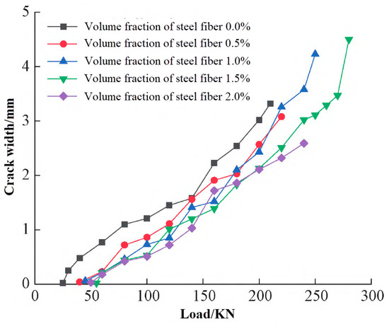
Figure 4.
Influence of different volume fractions of steel fiber on crack width [42].
Furthermore, to more effectively address the issue of structural brittle failure, the hybrid reinforcement approach combining steel bars and FRP bars has garnered the attention from researchers. Lau et al. [43] conducted flexural performance tests on beams with hybrid reinforcement, indicating that steel bars enhance the overall ductility and load-carrying capacity of FRP bar-reinforced members. The research results of Refai et al. [44] showed that beams with hybrid reinforcement exhibit superior flexural capacity. Studies by Leung et al. [45] demonstrated that the flexural capacity and failure modes of beams with hybrid reinforcement are greatly affected by concrete strength parameters. Zhou et al. [46] posited that the moderate enhancement of concrete strength grade can effectively enhance the flexural capacity of beams reinforced with hybrid reinforcement while fully utilizing the tensile strength of FRP bars.
In summary, the flexural bearing capacity of FRP bar-reinforced concrete beams is affected by various factors such as reinforcement ratio, concrete strength, fiber addition, and hybrid reinforcement. Adding fibers, appropriately increasing concrete strength, and adopting hybrid reinforcement are effective measures to improve the flexural capacity and ductility of beams. Currently, research on the mechanical behavior of beams reinforced with a hybrid of steel and FRP bars, especially regarding the reinforcement area ratio and hybrid reinforcement ratio, is relatively lagging, and the mechanical calculation theories predominantly rely on those for ordinary beam members. In the design of FRP-reinforced concrete beams, the following recommendations are proposed: add steel fibers (to reduce crack width and improve ductility/stiffness) or polypropylene fibers (to enhance crack resistance); adopt steel-FRP hybrid reinforcement (to improve ductility, bearing capacity and flexural performance); moderately increase concrete strength; and optimize the area ratio and reinforcement ratio of hybrid reinforcement. Therefore, it is essential to conduct in-depth investigations into the calculation methods for the flexural performance of beams reinforced with hybrid reinforcement, taking into account relevant structural design codes and experimental research. The related findings can serve as a theoretical basis for the design and engineering applications of beams reinforced with a hybrid of steel and FRP bars.
3. Research Progress on FRP Sheet–Concrete Members
3.1. Material Properties of FRP Sheets
FRP sheets possess excellent flexibility and sealing properties, enabling them to closely adhere to the structural surfaces to form a continuous protective layer. They exhibit outstanding durability, being capable of effectively resisting chemical erosion, ultraviolet aging, and microbial degradation. These sheets are particularly suitable for locations such as spillways that suffer severe water scouring and chemical corrosion. Their environmental adaptability ensures long-term stable operation under complex working conditions such as dry-wet alternation and high-low temperature cycles. Common composite materials in engineering include CFRP, GFRP, AFRP, BFRP, and LRS FRP (e.g., PET and PEN), with the differences in their main mechanical properties detailed in Table 2. GFRP exhibits poor UV aging resistance, with a strength retention rate of approximately 81–85%; its water resistance is moderate, while it has good freeze–thaw performance with no significant degradation in mechanical properties. CFRP has excellent UV aging resistance (strength retention rate over 92%), outstanding water resistance (minimal performance impact from water), and good freeze–thaw performance. AFRP has poor UV aging resistance (strength retention rate only around 45%) and relatively weak water resistance; its mechanical property retention rate is about 70% after freeze–thaw cycles. BFRP possesses excellent UV aging resistance (strength reduction of 8%), good water resistance, and stable freeze–thaw performance, meeting outdoor durability requirements. The environmental degradation of FRP sheets stems from the damage propagation among fibers, resin, and interfaces under different environmental actions: alkali erosion damages the resin structure and interface bonding, especially exacerbating the degradation of GFRP; moisture absorption plasticizes the resin, induces interfacial cracks, and reduces stiffness; freeze–thaw cycles promote crack propagation through “freezing expansion and thawing contraction” and often synergize with other factors to accelerate damage; ultraviolet radiation causes resin chain scission and surface aging embrittlement, eventually exposing fibers and leading to the attenuation of the overall mechanical properties of FRP sheets.

Table 2.
Physical and mechanical properties of different FRP sheets [47,48].
Overall, the type of internal fibers significantly influences the mechanical properties of the material. CFRP boasts ultra-high specific strength, high durability and fatigue resistance, a low coefficient of linear expansion, and relatively stable quality control, making it an outstanding high-performance material. GFRP, on the other hand, exhibits relatively weaker corrosion resistance, necessitating special attention when used in deteriorating environments. AFRP is notable for its significant creep behavior. BFRP is an environmentally friendly material with good mechanical properties, but its quality control is relatively poor [47]. The fracture strain of common PET and PEN can almost reach nearly 5–7 times that of other composite materials, which enhances the ductility of components (especially in seismic retrofitting), but they are not suitable for situations where there is a high demand for structural strength improvement [48,49]. Therefore, each type of FRP has its own particularities. Hence, in practical applications, it is essential to first clarify the design requirements before selecting the most appropriate FRP for implementation.
3.2. Interfacial Bond Properties Between FRP Sheet and Concrete
3.2.1. Failure Modes of the FRP Sheet–Concrete Interface
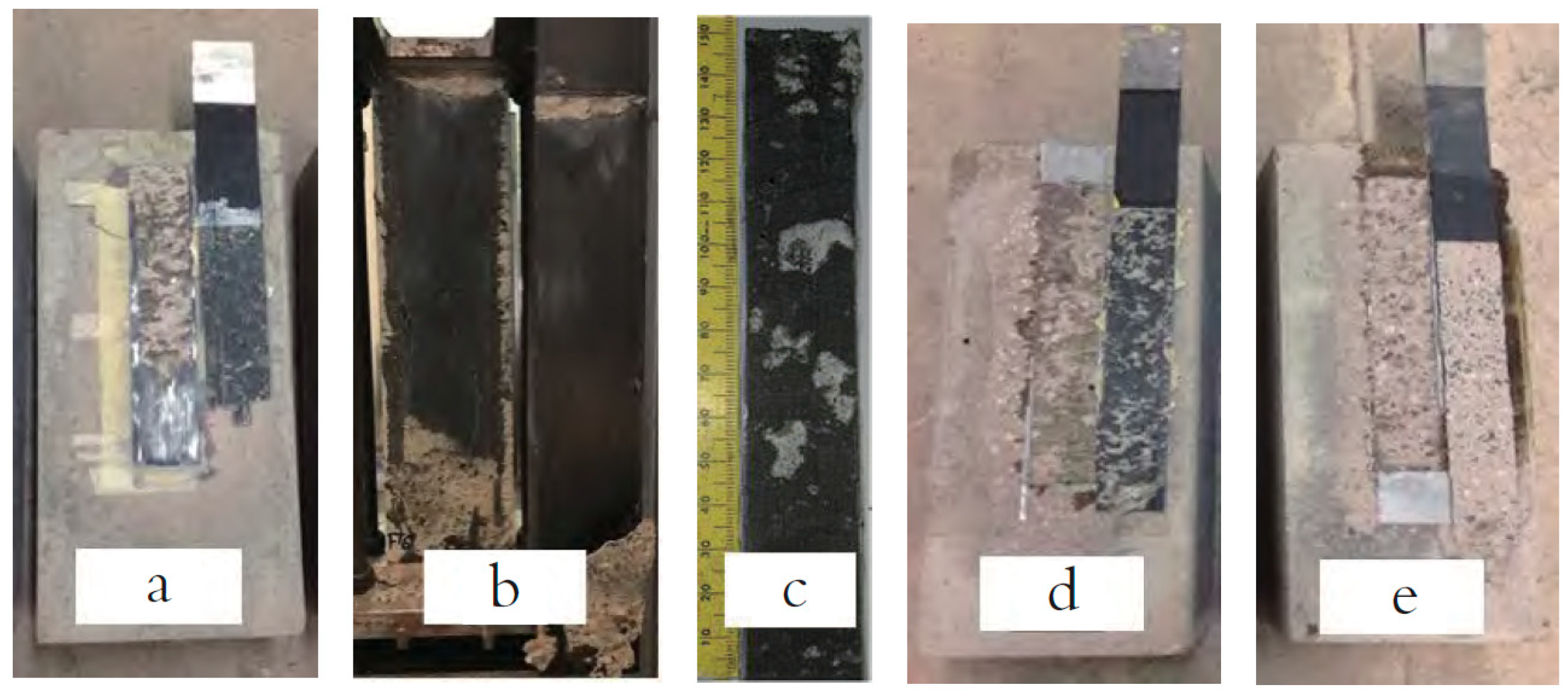
The fundamental prerequisite for the collaborative load-bearing between externally bonded FRP and concrete is effective interfacial stress transfer. However, the occurrence of debonding can severely disrupt the stress transfer, significantly diminishing the reinforcement effectiveness of externally bonded FRP and thereby accelerating the failure process of the strengthened member. There are two interface layers between FRP sheets and concrete, namely the interface layer between FRP and resin, and the interface layer between concrete and resin. When FRP is subjected to tensile force, failure may occur in FRP sheets, bonding resin, concrete, or at the two interfaces. In other words, the failure modes primarily encompass the following five types [50], as illustrated in Figure 5.

Figure 5.
Common FRP-concrete interface failure modes [50]: (a) Fracture or delamination failure of FRP; (b) Interface debonding failure between FRP and resin layer; (c) Internal shear failure of resin layer; (d) Interface debonding failure between resin layer and concrete; (e) Debonding failure caused by internal cracking of concrete.
3.2.2. Interfacial Bond Properties Between FRP Sheets and Concrete
Research on the mechanical properties of the FRP-concrete bonding interface is primarily conducted through independent interface tests, which mainly include single-shear tests [51,52,53,54,55,56], double-shear tests [57,58,59,60,61], and modified beam tests [62,63], among others. The bonding performance between FRP and substrate materials is directly related to the width, thickness, stiffness of the FRP sheet, which in turn determines the anchorage performance of the FRP sheet at the end. Through test research, Bizindavyi et al. [64] found that when the stress amplitude is equal, if the lower limit of the fatigue load is higher, the fatigue life of the interface significantly decreases compared to the specimens with a zero lower limit of fatigue load. Yun et al. [59] investigated the fatigue performance of FRP sheet under different anchorage systems and found that regardless of the number of fatigue loading cycles, the slope of the interface load-slip hysteresis loop remains unchanged significantly, that is, the stiffness of the interface does not degrade with the increase in the number of fatigue cycles. Daud et al. [50] experimentally demonstrated that preliminary fatigue loading induces a significant reduction in the interfacial debonding strain of CFRP plates, wherein higher-stiffness CFRP plates exhibit a more pronounced decrease in debonding strain.
The bond performance at the FRP sheet–concrete interface depends on the microstructures of the resin-concrete layer and fiber-resin layer. Its improvement can be achieved through the following approaches: creating mechanical interlocking by roughening the FRP resin layer or treating the concrete substrate; enhancing chemical bonding via adding coupling agents or oxidizing fibers; and optimizing the transition zone to suppress defects. The deterioration of this bond performance stems from environmental erosion, load actions, and construction defects.
The reasons for the degradation of FRP-concrete interfacial bond performance under fatigue loads are extremely complex, primarily attributed to the initiation and propagation of microcracks within the interfacial layer. Therefore, determining the characterization methodology for this mechanism assumes heightened significance. Addressing the issue of fatigue crack propagation at the bonded interface, through in-depth theoretical analysis and extensive experimental research, Zhou et al. [65] simplified the FRP-concrete interface as a Mode II crack propagation problem, constructed an interfacial damage accumulation model, and proposed that sufficient consideration must be given to the impact caused by the uncertainty of concrete cracks in the bonded zone.
The load-bearing capacity of the FRP-concrete interface exhibits a prominent characteristic, namely the existence of an “effective anchorage length”. When the bond length between FRP and concrete is less than the effective anchorage length Le, the load-bearing capacity of the bonded interface increases with the bond length. Conversely, when the bond length exceeds the effective anchorage length Le, the load-bearing capacity of the bonded interface remains constant, and an extended bond length beyond Le merely prolongs the failure process of the entire specimen, providing failure ductility for the bonded interface to a certain extent. Given that the load-bearing capacity of the bonded interface can be relatively straightforwardly obtained from experiments, numerous scholars both domestically and internationally have proposed bond strength models for the FRP-concrete interface. Representative models are presented in Table 3. Since the debonding failure of the FRP-concrete interface occurs within a thin layer of concrete, the concrete strength significantly influences the load-bearing capacity of the interface. Generally, under the same reinforcement conditions, a higher concrete strength grade corresponds to a higher load-bearing capacity of the FRP-concrete interface.

Table 3.
Summary of typical FRP-concrete interface bond strength models.
3.3. Ultimate Condition Compressive Behavior of FRP Sheet-Confined Concrete Columns
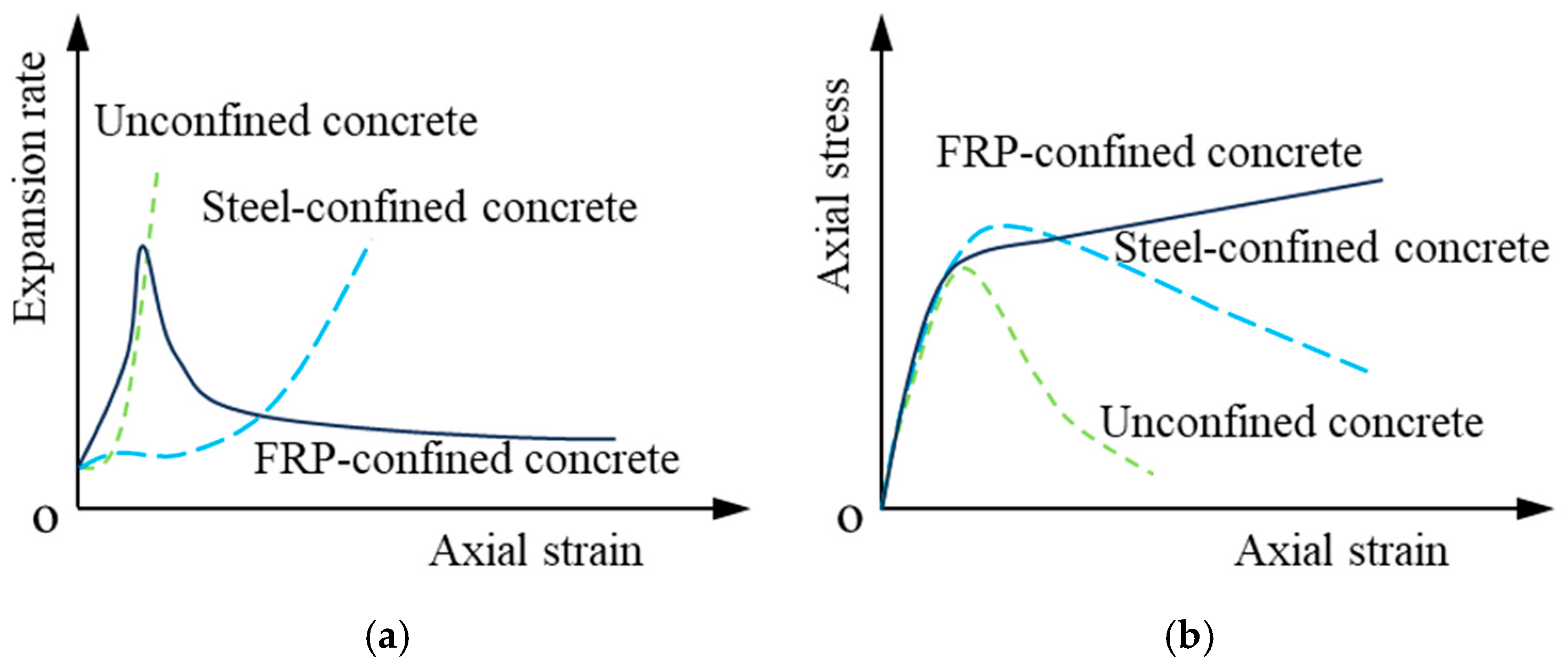
The compressive performance of FRP-confined concrete is crucial for its long-term performance evolution. Fardis and Khalili [75] discussed the variations in strength and ductility of various types of FRP-confined concrete under axial compression loads, revealing that their stress–strain curves significantly differ from those of traditionally steel tube-confined concrete. However, the relationship between the axial stress and the confining stress still adheres to the classical Richart model [76]. With further research, Mirmiran and Shahawy [77], along with Samaan et al. [78], discovered that due to the differing material properties of steel and FRP, there are variations in the confinement mechanisms for core concrete, namely active and passive confinement properties. This ultimately leads to notable differences in the expansion behavior and stress–strain relationships between FRP-confined concrete and steel-confined concrete, as illustrated in Figure 6.
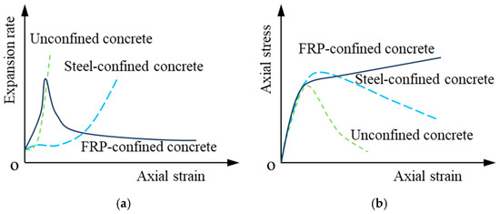
Figure 6.
Expansion characteristics and stress–strain curves of typically confined concrete: (a) Expansion rate [78]; (b) Stress–strain curve [79].
Relevant scholars have begun to conduct detailed discussions on the various factors influencing the FRP confinement effect. Toutanji [80], along with Xiao and Wu [81], found that as the number of external FRP layers increases, the strength and deformation capacity of confined concrete improve significantly. However, regardless of the external confinement stiffness, the ultimate failure is invariably controlled by the sudden brittle fracture of the FRP. Lam and Teng [82] discovered that in FRP-confined concrete, the measured fracture strain of FRP at specimen failure is significantly lower than the ultimate tensile strain obtained from material property tests. The primary reasons for this discrepancy are as follows: (1) the curvature change in FRP; (2) significant local deformations caused by concrete cracking; and (3) the presence of FRP overlapping areas in confined columns. These conclusions were later confirmed by research conducted by Chen et al. [83]. Wang [84] investigated the axial compression performance of FRP-confined concrete circular and square columns, finding that the size effect is not pronounced for circular columns but cannot be ignored for square columns, significantly influencing both the bearing capacity of the specimens and the effective fracture strain of the FRP. Additionally, the presence of longitudinal reinforcement enhances the bearing capacity of confined columns to a certain extent. Zeng et al. [85] conducted arc-rounding treatments on large-scale rectangular columns and performed axial compression tests, revealing that this technique is also effective for large-scale specimens, with the confinement effect increasing as the rise-to-span ratio improves. Furthermore, some scholars [86] have found that for common reinforced concrete columns, after FRP confinement, the increase in concrete compressive strength may lead to ultimate failure being controlled by column buckling. Consequently, Jiang and Teng [87] conducted in-depth research on this issue and proposed a predictive formula for the slenderness ratio limit applicable to FRP-confined reinforced concrete columns. On the other hand, relevant studies [88,89] indicate that as concrete strength increases, the strength development pattern of FRP-confined concrete becomes more dependent on the stiffness of the external FRP.
In scenarios where a moderate increase in strength is required but high ductility is also in demand, adopting a fully wrapped confinement configuration is not the optimal solution [90]. Saadatmanesh et al. [91] investigated the feasibility of using FRP strip confinement for reinforced concrete columns and found that the ductility coefficient continuously increases with an increase in strip thickness and a decrease in clear spacing. The experimental results from Barros et al. [92] indicated that the width, clear spacing, number of layers, stiffness of CFRP strips, and concrete strength grade all exert varying degrees of influence on the confinement efficiency. Wu et al. [88] compared the performance differences between fully wrapped and strip-confined columns under different concrete strengths and discovered that as concrete strength continuously increases, the FRP confinement efficiency gradually declines, particularly when using strip confinement. Recently, Zeng’s research team [93,94,95] conducted systematic experimental and theoretical analyses on the mechanical properties of FRP strip-confined concrete columns. They found that due to the existence of non-confined zones between the strips, there is significant discontinuity in axial and lateral deformations between the FRP strip-confined and non-confined zones of the specimens, leading to notable differences in their stress–strain behavior compared to traditionally fully wrapped confined concrete.
Research has found that, regardless of whether a fully wrapped FRP confinement or a strip confinement approach is employed, the ultimate failure is invariably controlled by the sudden brittle fracture of the FRP, without any forewarning. To address this issue, Professor Hadi’s research group [96] proposed the concept of non-uniform confinement, which involves a hybrid approach combining full wrapping and strip confinement. This method results in an uneven distribution of FRP thickness along the height of the entire member. Consequently, it can be inferred that failure will initially occur at the sections with thinner FRP confinement. However, since these sections are flanked by relatively thicker FRP strips, they will not lead to a sudden catastrophic failure, thereby allowing the failure process to exhibit certain forewarning characteristics.
4. Engineering Applications
FRP materials are increasingly being applied in dam engineering. With their characteristics of high strength, corrosion resistance, and light weight, they provide innovative solutions to solve the problems of traditional materials in the construction and maintenance of dams.
4.1. Large-Scale Application of GFRP Bars in Downstream Spillway Channel
4.1.1. Basic Information of the Project
The project located in Jizan City, the capital of Jizan Province in Saudi Arabia. Due to seasonal heavy rainfall and poor drainage, the region is prone to flooding. The construction of a 21.3 km-long spillway channel will play a crucial role in protecting urban infrastructure, ensuring community safety, and promoting economic development.
4.1.2. Project Construction Plan
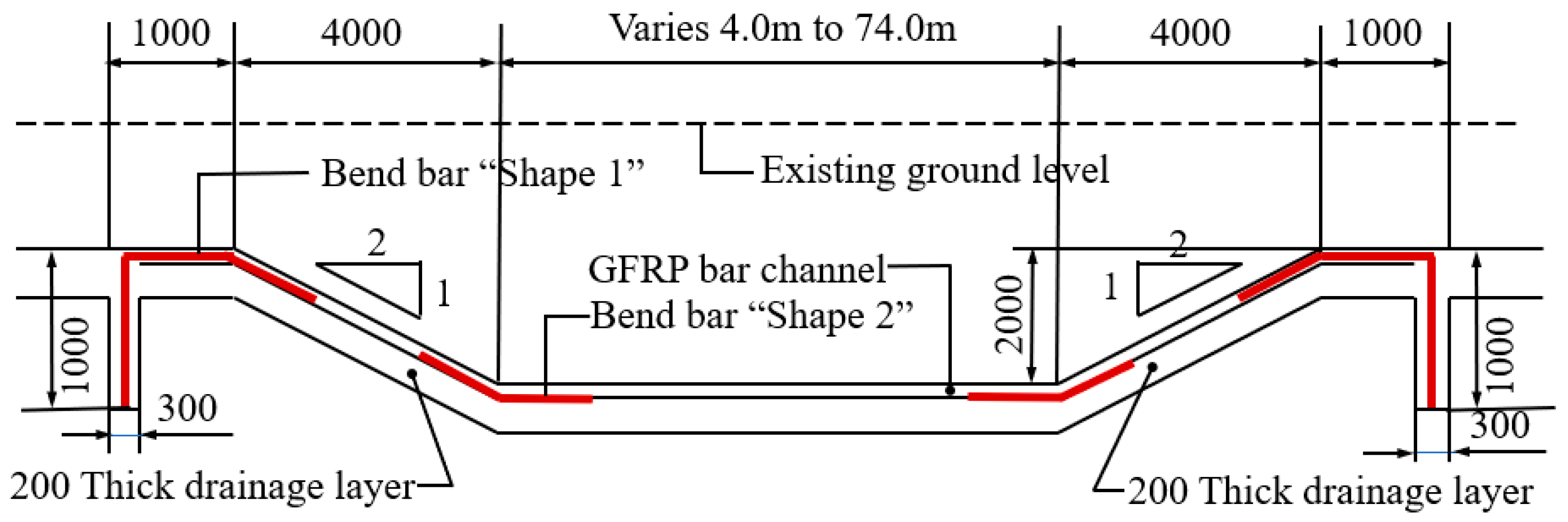
Traditionally, spillway channels are constructed with reinforced concrete. However, due to the coastal location of this project, under the combined effects of extreme stormy weather and wave attack, seawater can infiltrate and corrode the internal steel reinforcement, accelerating aging and concrete cracking. Considering these factors, it was decided to replace steel reinforcement with composite reinforcement as the enhancing material for the concrete. The project design drawing is detailed in Figure 7. The plan involves constructing a spillway channel that is 23,000 m long and 80 m wide, utilizing glass fiber reinforced polymer (GFRP) composite bars (both straight and stirrups) with a diameter of 13 mm. With over 11 million meters of GFRP bars used, this project has become the world’s largest-scale application case of composite reinforcement. It also marks that after more than 40 years of commercial use, composite reinforcement has finally become a material of choice for mainstream infrastructure projects.

Figure 7.
Design drawing of the downstream spillway channel.
GFRP is a type of composite material, typically consisting of vinyl ester resin and glass fibers. In addition to corrosion resistance, it exhibits high specific strength, electromagnetic neutrality, and excellent fatigue durability, with its material parameters detailed in Table 4. Furthermore, the relatively low weight of the reinforcement bars reduces transportation and installation costs, while also demonstrating good compatibility with concrete in terms of thermal expansion and stiffness.

Table 4.
Material parameters of GFRP bars.
4.1.3. Project Construction Process
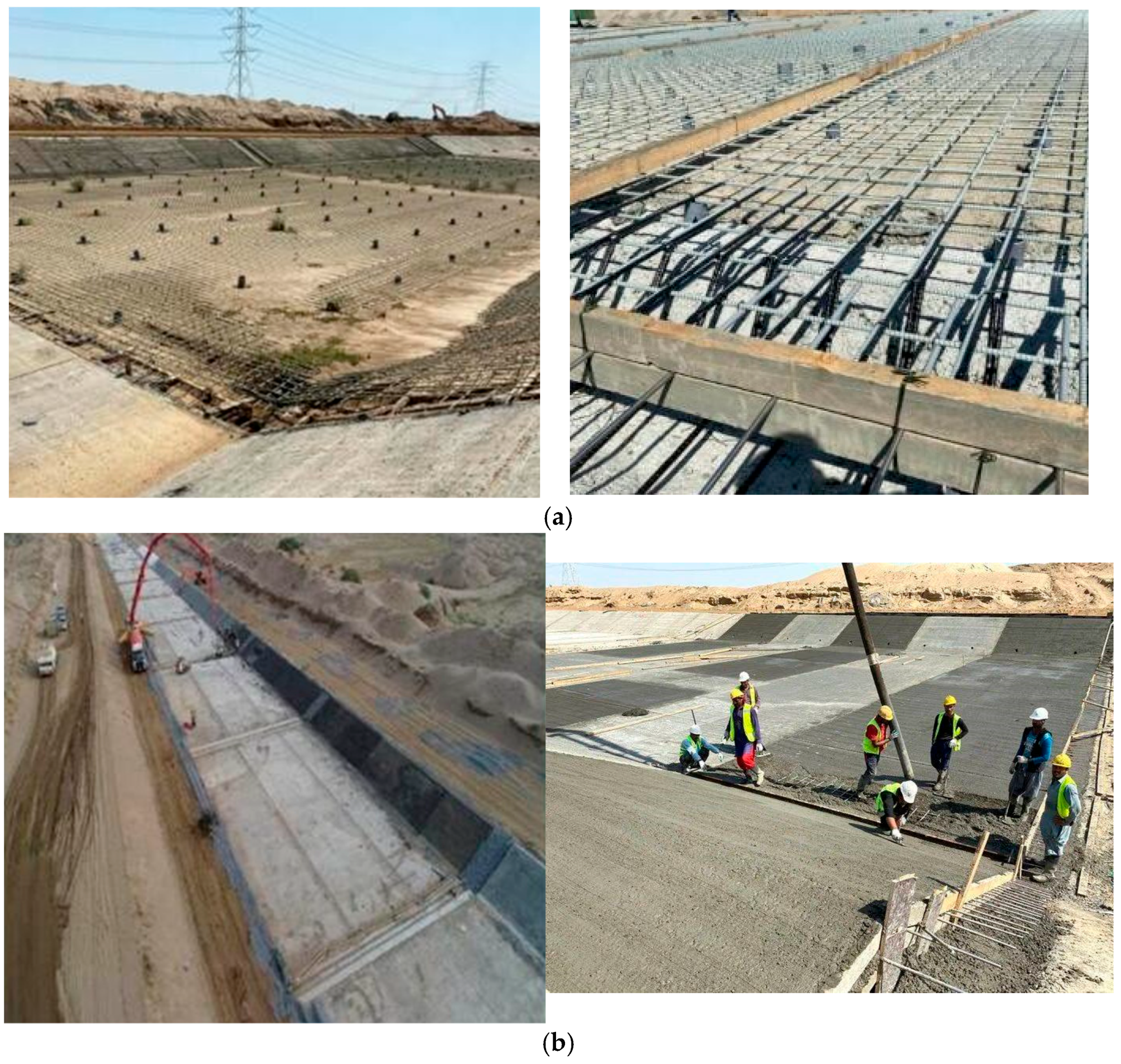
During the construction process, over 1500 cubic meters of concrete were poured daily. The entire project comprised 82% straight reinforcement bars and 18% stirrups. These were laid out according to the design plan, supported by round pipes below to ensure the appropriate height, and secured with stainless steel wire bindings. Concrete was poured from top to bottom, filling, compacting, and expelling air bubbles. Detailed illustrations are shown in Figure 8. The first key point was that, in response to changes in the structural design of the spillway channel, additional automatic grinding machines and new pipe bending machines were installed at the construction site. Another key point was that, in accordance with the design requirements of the spillway channel, an expansion joint needed to be installed on each slab, which required a curved reinforcement bar that could bend back onto itself. There were almost no similar bending construction techniques, but through repeated tests by pultrusion experts, the prefabrication of GFRP bars was successfully produced and they were promptly supplied to the project. During construction, another significant advantage of composite reinforcement bars became evident: ease of installation. Due to their weight being only 25% that of steel reinforcement bars, composite reinforcement bars were more convenient to handle and position, requiring fewer workers for the task.
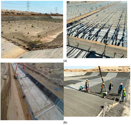
Figure 8.
Downstream spillway channel: (a) Mesh configuration of GFRP bars; (b) The procedure of concrete pouring.
4.1.4. Project Implementation Effect
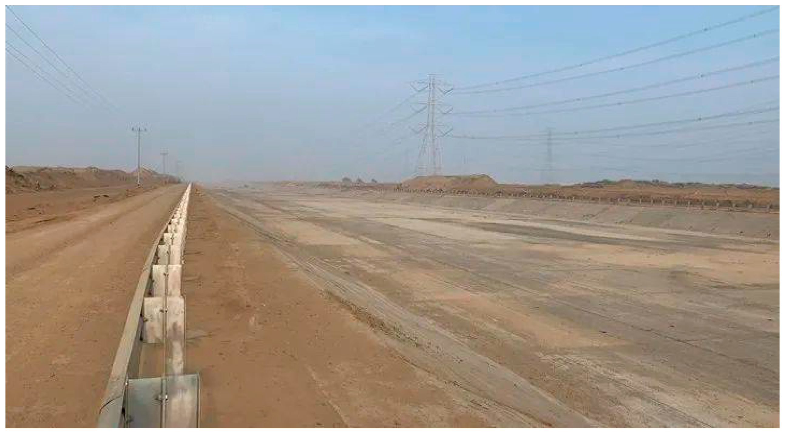
The use of high-performance GFRP reinforcement bars, with their exceptional durability (corrosion resistance and high chemical resistance), ensures a designed lifespan of 100 years for the spillway channel with minimal maintenance requirements. The channel protects people and the city from the devastation caused by floods. Nearly 3 years after project implementation, an investigation was conducted to evaluate the cost advantages and disadvantages of using GFRP reinforcement bars instead of epoxy-coated steel reinforcement. For a concrete slab measuring 30 × 30 × 0.2 m, substituting traditional steel reinforcement with the GFRP solution resulted in an 11% reduction in reinforcement material costs, a 10% decrease in concrete costs, a 42% drop in steel tie wire costs, a 100% reduction in crane expenses, and a 67% decrease in labor costs. The total direct cost savings for the GFRP reinforcement solution amounted to 21%. When considering life-cycle cost analysis, the savings become even more significant. For other similar large-scale projects, the use of GFRP reinforcement bars can also substantially reduce costs. The completed rendering of the project is detailed in Figure 9.
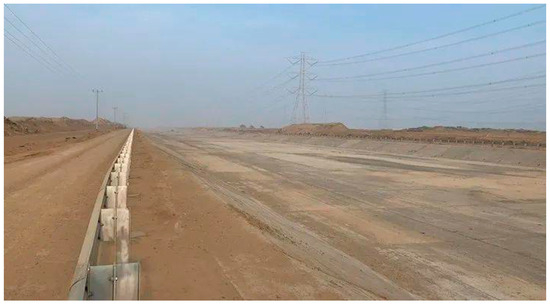
Figure 9.
Completion effect of the downstream spillway channel.
4.2. Application of FRP Sheets in Strengthening the Gantry Crane Rail Beam of Majingzi Dam
4.2.1. Basic Information of Majingzi Dam
The Majing Reservoir is located in the upstream gorge of the Qingxi River, characterized by a wide top and narrow bottom terrain with a significant elevation drop. It is a medium-sized reservoir with comprehensive functions such as power generation, irrigation, flood control, and aquaculture. The dam underwent two heightening projects in 1992 and 2007, raising its height from the original 17.3 m to 35.9 m and extending its length from 80 m to 153.4 m, with a storage capacity of 11.2 million cubic meters. Having been in operation for over 50 years since its completion, the reservoir’s gantry crane rail beam has exhibited various defects, including concrete spalling, steel reinforcement corrosion, and tensile cracking on both the beam bottom and sides, necessitating engineering reinforcement measures.
4.2.2. Engineering Reinforcement and Maintenance Plan
The gantry crane rail beam’s bottom and sides were reinforced by bonding 300 g/m2 carbon fiber reinforcement polymer sheets (CFRPS) with Type A adhesive. For the beam bottom, four layers of CFRPS with the same width as the beam bottom surface are adhered for reinforcement. At the mid-span of the beam, a full-section “U”-shaped hoop is formed using a single layer of 20 cm wide CFRPS. At other locations, uniformly spaced “U”-shaped hoops are created using a single layer of 20 cm wide CFRPS with a 20 cm interval. Additionally, two 10 cm wide CFRPS are adhered longitudinally along the top and middle of the beam to reinforce the “U”-shaped hoops, integrating the all CFRPS into a cohesive whole. The inspection parameters for the CFRPS are detailed in Table 5, while the inspection parameters for the accompanying Grade A adhesive are provided in Table 6.

Table 5.
Inspection data of CFRP sheets.

Table 6.
Inspection data of matching Class A adhesive.
4.2.3. Construction Technology for Engineering Reinforcement
CFRPS reinforcement is a novel strengthening technique developed in recent years by countries such as the United States and Japan for application in civil engineering. This method employs unidirectionally arranged CFRPS that are bonded to the surface of concrete structures at room temperature using epoxy resin adhesive. By tightly adhering to the concrete surface, the CFRPS and the concrete structure act as a new, integrated unit to jointly bear loads. This approach represents a highly straightforward and effective strengthening method. Unlike traditional steel plate bonding reinforcement, CFRPS reinforcement achieves efficient strengthening without increasing the load-bearing weight of the structure.
The construction process for CFRPS reinforcement is as follows: concrete surface treatment → CFRPS layout planning → adhesive formulation preparation → application of primer adhesive → leveling with leveling compound → application of topcoat adhesive → bonding of CFRPS → and final application of topcoat adhesive on the surface of CFRPS.
The main construction techniques are as follows:
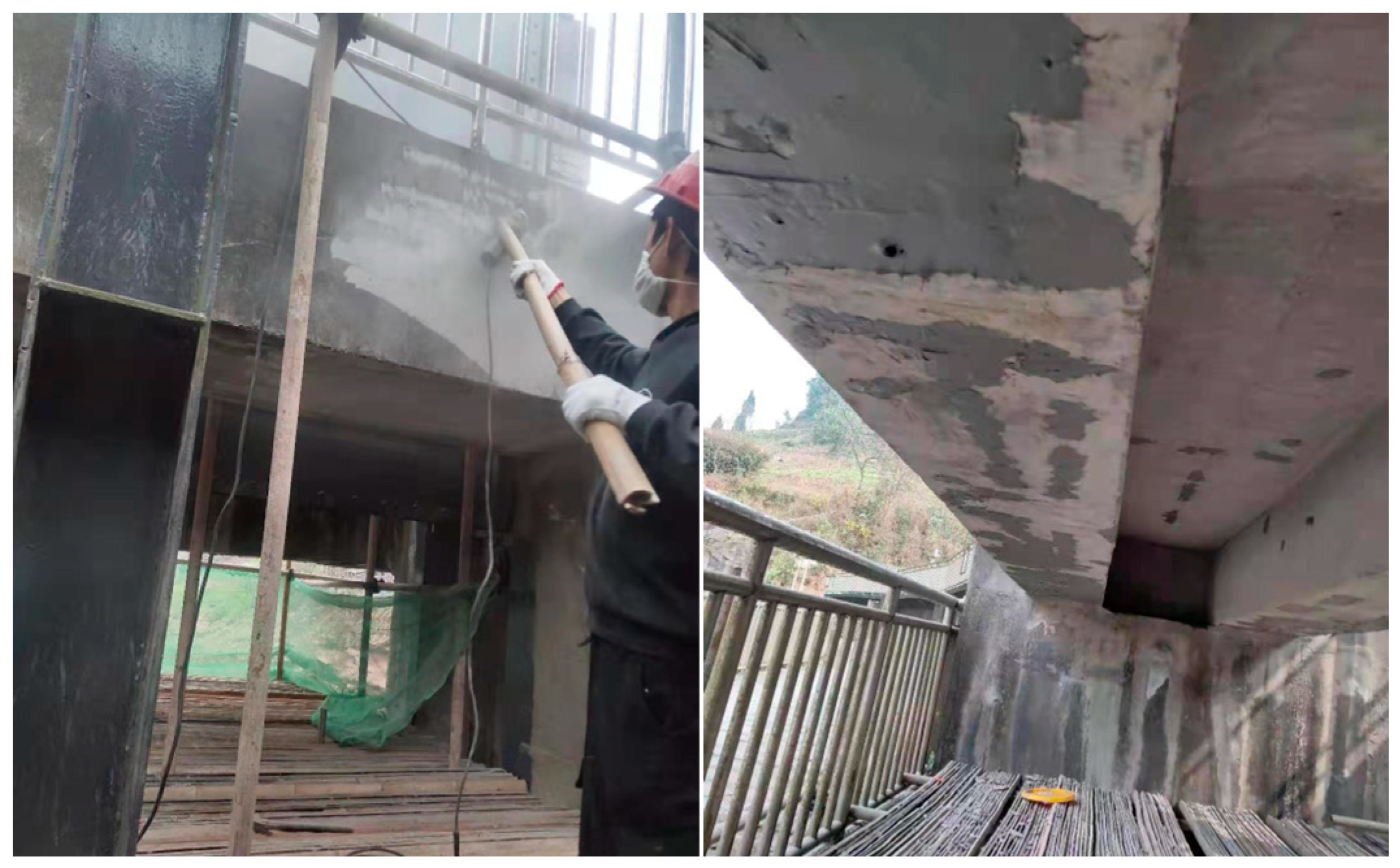
(1) Areas of the concrete surface exhibiting deterioration such as spalling, honeycombing, or corrosion should be removed. For larger areas of defective concrete, repair should be carried out using fine aggregate concrete with a grade of C30 or higher after removal. A concrete angle grinder should be used to eliminate laitance, oil stains, and other impurities from the concrete surface, ensuring that the concrete substrate is ground smooth. At corners, rounding off must be performed. See Figure 10 for details.
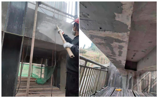
Figure 10.
Repair performance of concrete substrate surfaces.
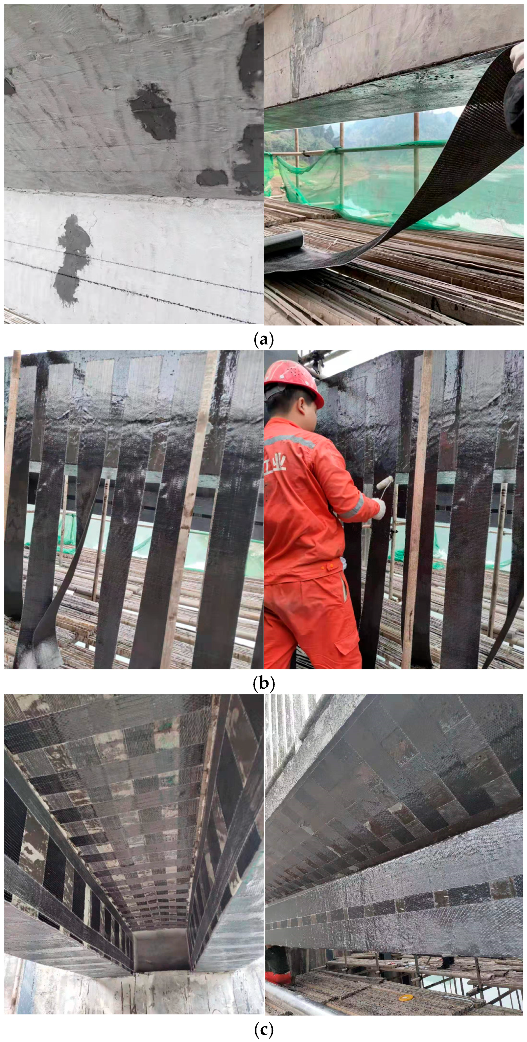
(2) According to the design requirements, it is necessary to layout the CFRPS on the concrete surface, apply the prepared and mixed adhesive evenly to the area to be bonded using a roller brush, use tools such as scrapers to bond the CFRPS to the target area, and repeatedly roll the surface of the CFRPS in the same direction with a grooved roller to remove air bubbles, ensuring that the CFRPS are fully impregnated with the adhesive, as shown in Figure 11.
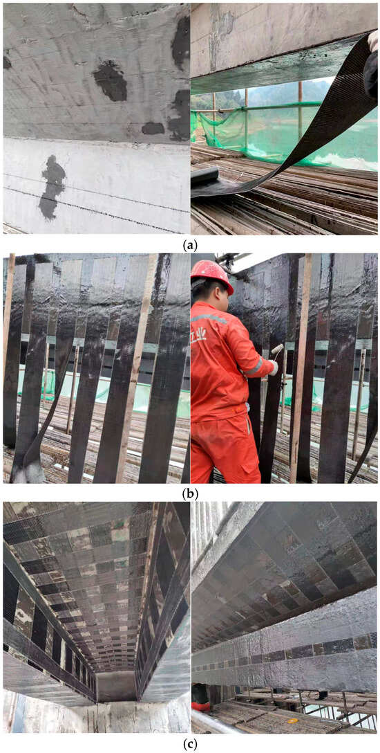
Figure 11.
Engineering application of CFRP sheets: (a) Configuration of CFRP sheets; (b) Bond of FRP sheets; (c) Formation of FRP sheets.
4.2.4. Effectiveness of CFRP Reinforcement Treatment
During the construction process, a set of bonded steel standard blocks was sampled under the same environmental conditions as the current construction scenario. Laboratory tests were conducted using a calibrated bond strength tester, revealing that the normal tensile bond strength values ranged from 3.1 to 3.6 MPa. These values met the requirement of being 1.5 times the standard tensile strength of the original concrete member (2.01 MPa), with the failure mode identified as cohesive failure (a normal failure mode). Additionally, based on the “Technical Specification for Strengthening Concrete Structures with Carbon Fiber Reinforced Polymer (CFRP) Sheets” (CECS146:2003), the results were assessed as qualified.
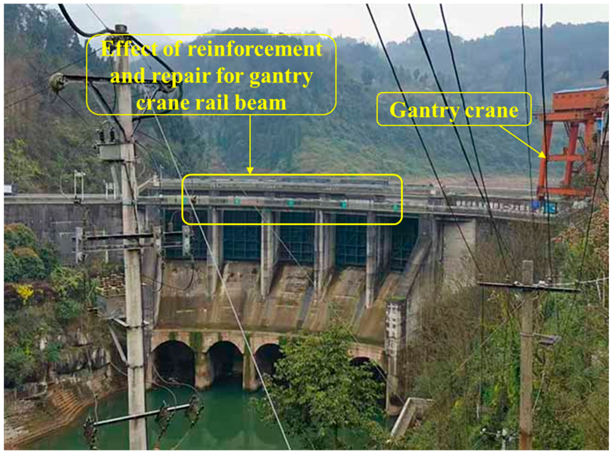
After the completion of the reinforcement and repair project for the gantry crane rail beam, several observations were made during the operation of the gantry crane. The CFRPS on the beam exhibited excellent adhesion to the concrete surface, with no signs of CFRPS tearing, debonding, or other abnormal phenomena. See Figure 12 for details.
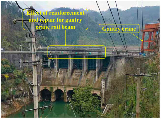
Figure 12.
Reinforcement and repair effect of gantry crane rail beam.
5. Exploration on New Application Scenarios of FRP
5.1. Seepage Prevention and Crack Resistance of FRP-Concrete Composite Dam
Based on the excellent seepage prevention and crack resistance properties of FRP composites, a composite structure featuring “crack resistance-seepage prevention-load bearing” can be designed for dam panels. The outer layer of the panel employs FRP composites (such as CFRP-concrete) to form a continuous seepage barrier and exert crack resistance by inhibiting the propagation of early shrinkage cracks or thermal cracks. The inner layer, composed of ordinary concrete, primarily provides compressive strength to ensure structural stability. This approach is suitable for applying FRP composites (e.g., FRP bars, FRP sheets) on the upstream or downstream faces of the dam for seepage prevention treatment, thereby blocking water penetration pathways and preventing dam body damage caused by seepage. Meanwhile, attention should be paid to reducing the environmental pollution caused by waste materials, and the recycling and disposal of FRP should also be considered in the future [97].
5.2. Reinforcement and Repair of Spillway
In practical engineering projects, dams frequently open their gates to discharge water to ensure flood control safety each year, resulting in spillways being constantly subjected to high-velocity water flow scouring. This often leads to the emergence of cracks or surface concrete damage, thereby posing a threat to the safety of hydraulic structures. To address this issue, the erosion resistance of FRP composites can be utilized by laying an FRP material protective layer (such as FRP-reinforced concrete or FRP sheets) on the spillway surface. This approach not only reduces water flow resistance, enhances cavitation erosion resistance, and improves wear resistance but also significantly shortens the downtime for maintenance due to the convenient and efficient construction of FRP materials.
5.3. Dam Safety Monitoring Equipment
By integrating FRP materials with sensors such as piezometers and strain gauges embedded within the dam structure, real-time monitoring of stress, strain, and temperature variations in the dam body can be achieved. Leveraging its exceptional corrosion resistance and structural stability, FRP materials provide a reliable protective barrier for the sensors, effectively isolating them from the effects of internal dampness and chemical erosion (e.g., chloride ions, sulfates). This significantly extends the service life of both the sensors and the entire monitoring system [98]. Furthermore, the coordinated deformation characteristics of FRP materials with the dam structure ensure that sensors accurately capture real-time data, offering continuous and reliable monitoring support for evaluating the safety status of the dam.
5.4. Anchorage Systems in Dam Retrofits for Different FRP Types
In dam retrofitting, the design of FRP anchorage systems must be adapted to the characteristics of different FRP types. Glass Fiber-Reinforced Polymer (GFRP), featuring low cost and relatively good ductility, is mostly used for the retrofitting of small-to-medium-sized dams or non-critical components. Its anchorage adopts a “mechanical anchorage + bonding assistance” configuration to reliably transfer moderate loads in a simple manner. Carbon Fiber-Reinforced Polymer (CFRP), which has high strength and high brittleness, is suitable for retrofitting critical dam components; it relies on a “prestressed anchorage + end constraint” system to achieve high-strength load transfer and suppress brittle failure. Aramid Fiber-Reinforced Polymer (AFRP), with excellent impact resistance and fatigue resistance, is applied to dam components subject to impact or alternating loads (e.g., spillways). Its anchorage employs a “flexible anchorage + protective coating” combination to ensure impact resistance and long-term weatherability. The core design principle of all types of anchorage systems is to align with the properties of FRP materials as well as the load and environmental requirements of the dam retrofitting components, thereby realizing the cooperative force transfer among FRP, the anchorage system, and the dam matrix, and ensuring the safety and durability of the retrofitting project.
6. Conclusions and Summary
6.1. Conclusions
This paper provides a comprehensive review of the performance of FRP materials, the interfacial bond performance between FRP materials and concrete, as well as their flexural or compressive properties, based on both domestic and international research. It summarizes the influencing factors related to the performance of FRP materials and concrete members, offering a thorough technical reference for the rational selection and optimized design of FRP materials in hydraulic structures. The main conclusions are as follows:
- (1)
- In practical engineering applications, focus should be placed on the surface treatment type of FRP bars, as it significantly affects the bond performance at the FRP bar–concrete interface. Meanwhile, the flexural capacity and ductility of FRP-reinforced concrete beams can be improved through three methods: incorporating steel fibers, increasing concrete strength, and adopting hybrid reinforcement.
- (2)
- For the application of FRP sheets, the effective anchorage length of FRP sheets and concrete strength should be key considerations, as they exert a significant impact on the bond strength at the FRP sheet–concrete interface. The non-uniform confinement form provides a feasible approach to addressing the sudden brittle failure of FRP-confined concrete columns (which occurs without warning) and offers important theoretical support for the rational design and performance optimization of FRP in engineering applications such as concrete structure retrofitting.
- (3)
- Based on the advantages of FRP composites and actual conditions, they can be widely applied in hydraulic structures such as dikes, sluice gates, and aqueducts, providing innovative solutions for the construction, monitoring, repair, and reinforcement of hydraulic buildings.
6.2. Summary
Research on the shear performance of FRP composites is notably insufficient, necessitating the exploration of relevant theories, methods, or technologies to substantially enhance their shear capacity. Meanwhile, the selection of FRP materials, structural design specifications, and construction process standards for different engineering scenarios remains incomplete, hindering their standardized application. Future efforts should focus on investigating the long-term performance evolution patterns and predictive models of FRP materials under complex environmental conditions; refining design standards and construction techniques; developing novel low-cost, high-performance FRP composite structures; and promoting their large-scale and efficient application in hydraulic structures and other fields. This study actually emphasizes the potential macro-applications of FRP in dam safety risk mitigation measures, such as reinforcement measures. However, the use of externally bonded steel-reinforced polymer (SRP) composites [99] for reinforcement is also a viable solution, which remains to be investigated in future work.
Author Contributions
Conceptualization, L.Z., P.L., F.X. and G.B.; data curation, L.Z., F.X. and P.L.; formal analysis, L.Z. and F.X.; funding acquisition, P.L. and D.Y.; investigation, L.Z., P.L. and J.C.; methodology, L.Z. and F.X.; project administration, G.B., J.C., D.Y. and L.P.; resources, G.B., J.C. and D.Y.; software, L.Z.; supervision, G.B., J.C., L.P. and D.Y.; validation, L.Z. and P.L.; visualization, L.Z. and P.L.; writing—original draft, L.Z., F.X. and P.L.; writing—review and editing, L.Z., F.X., P.L. and G.B. All authors have read and agreed to the published version of the manuscript.
Funding
This research was supported by the National Natural Science Foundation of China (No.52409178).
Data Availability Statement
The original contributions presented in this study are included in the article. Further inquiries can be directed to the corresponding author.
Conflicts of Interest
The all authors declare that the research was conducted in the absence of any commercial or financial relationships that could be construed as a potential conflict of interest.
References
- Nemnem, A.M.; Tanim, A.H.; Nahian, A.; Khan, S.; Goharian, E.; Imran, J. How extreme rainfall and failing dams unleashed the Derna flood disaster. Nat. Commun. 2025, 16, 4191. [Google Scholar] [CrossRef]
- Adamo, N.; Al-Ansari, N.; Sissakian, V.; Laue, J.; Knutsson, S. Dam safety: Technical problems of ageing concrete dams. J. Earth Sci. Geotech. Eng. 2020, 10, 241–279. [Google Scholar]
- Silva, L.C.; de Oliveira Mattos, U.A.; da Silva, J.C. Dams safety: An analysis of safety management and the difficulties of its supervision. Ciência Nat. 2023, 45, e6. [Google Scholar] [CrossRef]
- Imperatore, S.; Rinaldi, Z. Cracking in reinforced concrete structures damaged by artificial corrosion: An overview. Open Constr. Build. Technol. J. 2019, 13, 199. [Google Scholar] [CrossRef]
- Ojha, P.N.; Trivedi, A.; Singh, B.; Adarsh Kumar, N.S.; Patel, V.; Gupta, R.K. High performance fiber reinforced concrete–for repair in spillways of concrete dams. Res. Eng. Struct. Mater. 2021, 7, 505–522. [Google Scholar] [CrossRef]
- Uddin, N. Developments in Fiber-Reinforced Polymer (FRP) Composites for Civil Engineering; Woodhead Publishing: Delhi, India, 2013. [Google Scholar]
- Das, S.C.; Nizam, M. Applications of fiber reinforced polymer composites (FRP) in civil engineering. Int. J. Adv. Struct. Geotech. Eng. 2014, 3, 299–309. [Google Scholar]
- Altunişik, A.C.; Günaydin, M.; Sevim, B.; Bayraktar, A.; Adanur, S. CFRP composite retrofitting effect on the dynamic characteristics of arch dams. Soil Dyn. Earthquake Eng. 2015, 74, 1–9. [Google Scholar] [CrossRef]
- Kalamkarov, A.; Saha, G.; Rokkam, S.; Newhook, J.; Georgiades, A. Strain and deformation monitoring in infrastructure using embedded smart FRP reinforcements. Compos. Part B Eng. 2005, 36, 455–467. [Google Scholar] [CrossRef]
- Baena, M.; Torres, L.; Turon, A.; Barris, C. Experimental study of bond behaviour between concrete and FRP bars using a pull-out test. Compos. Part B Eng. 2009, 40, 784–797. [Google Scholar] [CrossRef]
- GB 50608-2020; Technical Standard for Fiber Reinforced Polymer (FRP) in Construction. China Planning Press: Beijing, China, 2020.
- Feng, G.; Zhu, D.; Guo, S.; Rahman, M.Z.; Jin, Z.; Shi, C. A review on mechanical properties and deterioration mechanisms of FRP bars under severe environmental and loading conditions. Cem. Concr. Comp. 2022, 134, 104758. [Google Scholar] [CrossRef]
- EI-Sayed, A.K.; EI-Salakawy, E.F.; Benmokrane, B. Shear strength of FRP-reinforced concrete beams without transverse reinforcement. ACI Mater. J. 2006, 103, 235. [Google Scholar]
- Allen, J.H.; Felder, A.L.; McDermott, J.F.; Azizinamini, A.; Frosch, R.J.; Mitchell, D.; Matamoros, A.B. Bond and Development of Straight Reinforcing Bars in Tension; Report no. ACI 408R-03; American Concrete Institute: Detroit, MI, USA, 2003. [Google Scholar]
- Gao, J.; Fan, L.Y. Experiment on bond performance between CFRP bar and seawater sea sand concrete and its working mechanism. Acta Mater. Compos. Sin. 2022, 39, 1194–1204. (In Chinese) [Google Scholar]
- Wang, L.; Li, W.; Chen, S.; Mao, Y.D.; Wang, K. Effects of sea water soaking on the bonding properties of FRP bars-coral concrete. Acta Mater. Compos. Sin. 2018, 35, 3458–3465. (In Chinese) [Google Scholar]
- Taha, A.; Alnahhal, W. Bond durability and service life prediction of BFRP bars to steel FRC under aggressive environmental conditions. Compos. Struct. 2021, 269, 114034. [Google Scholar] [CrossRef]
- Zhang, B.; Zhu, H.; Cao, R.M.; Ding, J.; Chen, X. Feasibility of using geopolymers to investigate the bond behavior of FRP bars in seawater sea-sand concrete. Constr. Build. Mater. 2021, 282, 122636. [Google Scholar] [CrossRef]
- Wang, J.Z.; Xiao, F.D.; Lai, Z.Y.; Yang, J.L.; Tian, S.Y. Bond of FRP bars with different surface characteristics to concrete. Structures 2024, 59, 105731. [Google Scholar] [CrossRef]
- Solyom, S.; Balázs, G.L. Bond of FRP bars with different surface characteristics. Constr. Build. Mater. 2020, 264, 119839. [Google Scholar] [CrossRef]
- Achillides, Z.; Pilakoutas, K. Bond behavior of fiber reinforced polymer bars under direct pullout conditions. J. Compos. Constr. 2004, 8, 173–181. [Google Scholar] [CrossRef]
- Firas, S.A.; Gilles, F.; Robert, L.R. Bond between carbon fibre-reinforced polymer (CFRP) bars and ultra high performance fibre reinforced concrete (UHPFRC): Experimental study. Constr. Build. Mater. 2011, 25, 479–485. [Google Scholar] [CrossRef]
- Refai, A.E.; Ammar, M.A.; Masmoudi, R. Bond performance of basalt fiber reinforced polymer bars to concrete. J. Compos. Constr. 2015, 19, 04014050. [Google Scholar] [CrossRef]
- Shen, D.; Ojha, B.; Shi, X.; Zhang, H.; Shen, J. Bond stress-slip relationship between basalt fiber-reinforced polymer bars and concrete using a pull-out test. J. Reinf. Plast. Comp. 2016, 35, 747–763. [Google Scholar] [CrossRef]
- Chang, Y.F.; Wang, Y.L.; Wang, M.F.; Zhou, Z.; Ou, J.P. Bond durability and degradation mechanism of GFRP bars in seawater sea-sand concrete under the coupling effect of seawater immersion and sustained load. Constr. Build. Mater. 2021, 307, 124878. [Google Scholar] [CrossRef]
- Zeng, J.J.; Liao, J.J.; Yan, Z.G.; Guo, Y.C.; Zhou, J.K.; Huang, Z.H.; Zhang, L.H. Bond behavior between GFRP bars and seawater sea-sand fiber-reinforced ultra-high strength concrete. Eng. Struct. 2022, 254, 113787. [Google Scholar] [CrossRef]
- Huang, Z.H. Bond-Slip Behavior Between GFRP Bar and High Strength PE Fiber Reinforced Seawater Sea-Sand Concrete. Master’s Thesis, Guangdong University of Technology, Guangzhou, China, 2021. (In Chinese). [Google Scholar]
- Tong, G.Q. Experimental Research on the Bond Performance of FRP Bars in Seawater and Sea Sand Concrete. Master’s Thesis, Hunan University, Changsha, China, 2020. (In Chinese). [Google Scholar]
- Su, X.; Yin, S.P.; Zhao, Y.D.; Hua, Y.T. Experimental study on bond behavior between BFRP bars and seawater sea-sand concrete. J. Cent. South. Univ. 2021, 28, 2193–2205. [Google Scholar] [CrossRef]
- Zemour, N.; Asadian, A.; Ahmed, E.A.; Khayat, K.H.; Benmokrane, B. Experimental study on the bond behavior of GFRP bars in normal and self-consolidating concrete. Constr. Build. Mater. 2018, 189, 869–881. [Google Scholar] [CrossRef]
- Liu, H.X.; Yang, J.W.; Wang, X.Z. Bond behavior between BFRP bar and recycled aggregate concrete reinforced with basalt fiber. Constr. Build. Mater. 2017, 135, 477–483. [Google Scholar] [CrossRef]
- Wang, Z.K.; Zhao, X.L.; Xian, G.J.; Wu, G.; Singh Raman, R.K.; Al-Saadi, S. Durability study on interlaminar shear behaviour of basalt-, glass-and carbon-fibre reinforced polymer (B/G/CFRP) bars in seawater sea sand concrete environment. Constr. Build. Mater. 2017, 156, 985–1004. [Google Scholar] [CrossRef]
- Nepomuceno, E.; Sena-Cruz, J.; Correia, L.; Antino, T.D. Review on the bond behavior and durability of FRP bars to concrete. Constr. Build. Mater. 2021, 287, 123042. [Google Scholar] [CrossRef]
- Peng, K.D.; Zeng, J.J.; Huang, B.T.; Huang, J.Q.; Zhuge, Y.; Dai, J.G. Bond performance of FRP bars in plain and fiber-reinforced geopolymer under pull-out loading. J. Build. Eng. 2022, 57, 104893. [Google Scholar] [CrossRef]
- Shen, X.; Li, B.; Shi, W.; Chen, Y.T. Numerical study on flexural behaviour of FRP reinforced concrete beams with compression yielding blocks. Case Stud. Constr. Mater. 2022, 17, e01169. [Google Scholar]
- Elgabbas, F.; Ahmed, E.A.; Benmokrane, B. Flexural behavior of concrete beams reinforced with ribbed basalt-FRP bars under static loads. J. Compos. Constr. 2017, 21, 04016098. [Google Scholar] [CrossRef]
- Khorasani, A.M.M.; Esfahani, M.R.; Sabzi, J. The effect of transverse and flexural reinforcement on deflection and cracking of GFRP bar reinforced concrete beams. Compos. Part B Eng. 2019, 161, 530–546. [Google Scholar] [CrossRef]
- Sun, S.J.; Guo, Y.P.; Gui, P.; Xing, L.L.; Mei, K.H. Flexural behaviour of steel–basalt fibre composite bar-reinforced concrete beams. Eng. Struct. 2023, 289, 116246. [Google Scholar] [CrossRef]
- Zhu, H.T.; Cheng, S.Z.; Gao, D.Y.; Neaz, S.M.; Li, C.C. Flexural behavior of partially fiber-reinforced high-strength concrete beams reinforced with FRP bars. Constr. Build. Mater. 2018, 161, 587–597. [Google Scholar] [CrossRef]
- Wang, H.Z.; Belarbi, A. Ductility characteristics of fiber-reinforced-concrete beams reinforced with FRP rebars. Constr. Build. Mater. 2011, 25, 2391–2401. [Google Scholar] [CrossRef]
- Li, Z.Z.; Zhu, H.T.; Du, C.X.; Cao, D.Y.; Yuan, J.S.; Wen, C.C. Experimental study on cracking behavior of steel fiber-reinforced concrete beams with BFRP bars under repeated loading. Compos. Struct. 2021, 267, 113878. [Google Scholar] [CrossRef]
- Zhu, H.T.; Cheng, S.Z.; Gao, D.Y.; Gui, G.H. Bending experimental study and crack width calculation method of high-strength concrete beams reinforced with BFRP bars and steel fiber. J. Build. Struct. 2020, 41, 133–142. [Google Scholar]
- Lau, D.; Pam, H.J. Experimental study of hybrid FRP reinforced concrete beams. Eng. Struct. 2010, 32, 3857–3865. [Google Scholar] [CrossRef]
- Refai, A.E.; Abed, F.; Rahmani, A.A. Structural performance and serviceability of concrete beams reinforced with hybrid (GFRP and steel) bars. Constr. Build. Mater. 2015, 96, 518–529. [Google Scholar] [CrossRef]
- Leung, H.Y.; Balendran, R.V. Flexural behaviour of concrete beams internally reinforced with GFRP rods and steel rebars. Struct. Surv. 2003, 21, 146–157. [Google Scholar] [CrossRef]
- Zhou, B.B.; Wu, R.Y.; Liu, Y.Q.; Zhang, X.H.; Yin, S.P. Flexural strength design of hybrid FRP-steel reinforced concrete beams. Materials 2021, 14, 6400. [Google Scholar] [CrossRef]
- Amran, Y.H.M.; Alyousef, R.; Rashid, R.S.M.; Alabduljabbar, H.; Hung, C.C. Properties and applications of FRP in strengthening RC structures: A review. Structures 2018, 16, 208–238. [Google Scholar] [CrossRef]
- Ye, Y.Y.; Liang, S.D.; Feng, P.; Zeng, J.J. Recyclable LRS FRP composites for engineering structures: Current status and future opportunities. Compos. Part. B Eng. 2021, 212, 108689. [Google Scholar] [CrossRef]
- Dai, J.G.; Bai, Y.L.; Teng, J.G. Behavior and modeling of concrete confined with FRP composites of large deformability. J. Compos. Constr. 2011, 15, 963–973. [Google Scholar] [CrossRef]
- Daud, R.A.; Cunningham, L.S.; Wang, Y.C. Static and fatigue behaviour of the bond interface between concrete and externally bonded CFRP in single shear. Eng. Struct. 2015, 97, 54–67. [Google Scholar] [CrossRef]
- Bizindavyi, L.; Neale, K.W.; Erki, M.A. Experimental Investigation of Bonded Fiber Reinforced Polymer-Concrete Joints under Cyclic Loading. J. Compos. Constr. 2003, 7, 127–134. [Google Scholar] [CrossRef]
- Carloni, C.; Subramaniam, K.V.; Savoia, M.; Mazzotti, C. Experimental determination of FRP-concrete cohesive interface properties under fatigue loading. Compos. Struct. 2012, 94, 1288–1296. [Google Scholar] [CrossRef]
- Cornetti, P.; Muñoz-Reja, M.; Mantič, V. Cohesive crack models and finite fracture mechanics analytical solutions for FRP-concrete single-lap shear test: An overview. Theor. Appl. Fract. Mech. 2022, 122, 103529. [Google Scholar] [CrossRef]
- Calabrese, A.S.; Colombi, P.; D'antino, T. Analytical solution of the full-range behavior of adhesively bonded FRP-steel joints made with toughened adhesives. Eng. Fract. Mech. 2023, 292, 109569. [Google Scholar] [CrossRef]
- Zhang, W.; Tang, Z. Numerical modeling of response of CFRP concrete interfaces subjected to fatigue loading. J. Compos. Constr. 2021, 25, 04021043. [Google Scholar] [CrossRef]
- Al-Saoudi, A.; Kalfat, R.; Al-Mahaidi, R.; Cervenka, J.; Pryl, D. Numerical and experimental investigation into the fatigue life of FRP bonded to concrete and anchored with bidirectional fabric patches. Eng. Struct. 2021, 239, 112335. [Google Scholar] [CrossRef]
- Ferrier, E.; Bigaud, D.; Hamelin, P.; Bizindavyi, L.; Neale, K.W. Fatigue of CFRPs externally bonded to concrete. Mater. Struct. 2005, 38, 39–46. [Google Scholar] [CrossRef]
- Diab, H.; Wu, Z. Nonlinear constitutive model for time-dependent behavior of FRP-concrete interface. Compos. Sci. Tech. 2007, 67, 2323–2333. [Google Scholar] [CrossRef]
- Yun, Y.; Wu, Y.F.; Tang, W.C. Performance of FRP bonding systems under fatigue loading. Eng. Struct. 2008, 30, 3129–3140. [Google Scholar] [CrossRef]
- Ko, H.; Sato, Y. Bond stress-slip relationship between FRP sheet and concrete under cyclic load. J. Compos. Constr. 2007, 11, 419–426. [Google Scholar] [CrossRef]
- Fathi, A.; El-Saikaly, G.; Chaallal, O. Fatigue behavior in the Carbon-Fiber-Reinforced Polymer-to-Concrete bond by cyclic pull-out test: Experimental and analytical study. J. Compos. Constr. 2023, 27, 04023033. [Google Scholar] [CrossRef]
- Li, K.; Zhao, D.P.; Wang, X.L.; Feng, H.; Zou, X.Y. Investigation of crack growth in CFRP-concrete interface under fatigue loading. Structures 2021, 34, 356–367. [Google Scholar] [CrossRef]
- Yuan, H.; Luo, G.Y.; Liu, C.; Zeng, L. Interfacial properties of CFRP sheets and concrete subjected to variable amplitude fatigue loading. Struct. Concr. 2021, 22, 1927–1945. [Google Scholar] [CrossRef]
- Bizindavyi, L.; Neale, K. Transfer lengths and bond strengths for composites bonded to concrete. J. Compos. Constr. 1999, 3, 153–160. [Google Scholar] [CrossRef]
- Zhou, H.; Zhang, S.S.; Fernando, D.; Huang, T.L. The bond-behaviour of CFRP-to-concrete bonded joints under fatigue loading: A damage accumulation model. Eng. Fract. Mech. 2023, 284, 109272. [Google Scholar] [CrossRef]
- Chen, J.F.; Teng, J. Anchorage strength models for FRP and steel plates bonded to concrete. J. Struct. Eng. 2001, 127, 784–791. [Google Scholar] [CrossRef]
- Liu, X.Z. Studies on FRP-Concrete Interface. Ph.D. Thesis, Tsinghua University, Beijing, China, 2004. (In Chinese). [Google Scholar]
- Sato, Y.; Vecchio, F.J. Tension stiffening and crack formation in reinforced concrete members with fiber-reinforced polymer sheets. J. Struct. Eng. 2003, 129, 717–724. [Google Scholar] [CrossRef]
- Izumo, K.; Saeki, N.; Fukao, M.; Takashi, H. Bond behavior and strength between fiber sheets and concrete. Trans. Jpn. Concr. Inst. 2000, 21, 423–430. [Google Scholar]
- Gemert, V.D. Force transfer in epoxy bonded steel/concrete joints. Int. J. Adhes. 1980, 1, 67–72. [Google Scholar] [CrossRef]
- Chaallal, O.; Nollet, M.J.; Perraton, D. Strengthening of reinforced concrete beams with externally bonded fiber-reinforced-plastic plates: Design guidelines for shear and flexure. Can. J. Civ. Eng. 1998, 25, 692–704. [Google Scholar] [CrossRef]
- Yoshizawa, H. Analysis of debonding fracture properties of CFS strengthened RC member subject to tension. In Non-Metallic (FRP) Reinforcement for Concrete Structures, Proceedings of the Third International Symposium on FRP Reinforcement for Concrete Structures (FRPRCS-3), Sapporo, Japan, 14–16 October 1997; Japan Concrete Institute: Tokyo, Japan, 1997; pp. 287–294. [Google Scholar]
- Wei, M.W.; Xie, J.H.; Zhang, H.; Li, J.L. Bond-slip behaviors of BFRP-to-concrete interfaces exposed to wet/dry cycles in chloride environment. Compos. Struct. 2019, 219, 185–193. [Google Scholar] [CrossRef]
- Chalot, A.; Michel, L.; Ferrier, E. Experimental study of external bonded CFRP-concrete interface under low cycle fatigue loading. Compos. B. Eng. 2019, 177, 107255. [Google Scholar] [CrossRef]
- Fardis, M.N.; Khalili, H. Concrete encased in fiberglass-reinforced plastic. J. Proc. 1981, 78, 440–446. [Google Scholar]
- Richart, F.E.; Brandtzaeg, A.; Brown, R.L. A Study of the Failure of Concrete Under Combined Compressive Stresses; Bulletin No. 185; University of Illinois at Urbana Champaign: Champaign, IL, USA, 1928. [Google Scholar]
- Mirmiran, A.; Shahawy, M. Dilation characteristics of confined concrete. Mech. Cohes. Frict. Mater. 1997, 2, 237–249. [Google Scholar] [CrossRef]
- Samaan, M.; Mirmiran, A.; Shahawy, M. Model of concrete confined by fiber composites. J. Struct. Eng. 1998, 124, 1025–1031. [Google Scholar] [CrossRef]
- Wu, Y.F.; Wei, Y. General stress-strain model for steel- and FRP-confined concrete. J. Compos. Constr. 2015, 19, 04014069. [Google Scholar] [CrossRef]
- Toutanji, H.A. Stress-strain characteristics of concrete columns externally confined with advanced fiber composite sheets. ACI Mater. J. 1999, 96, 397–404. [Google Scholar] [CrossRef]
- Xiao, Y.; Wu, H. Compressive behavior of concrete confined by carbon fiber composite jackets. J. Mater. Civ. Eng. 2000, 12, 139–146. [Google Scholar] [CrossRef]
- Lam, L.; Teng, J.G. Ultimate condition of fiber reinforced polymer-confined concrete. J. Compos. Constr. 2004, 8, 539–548. [Google Scholar] [CrossRef]
- Chen, J.F.; Li, S.Q.; Bisby, L.A. Factors affecting the ultimate condition of FRP-wrapped concrete columns. J. Compos. Constr. 2013, 17, 67–78. [Google Scholar] [CrossRef]
- Wang, Y.F.; Wu, H.L. Size effect of concrete short columns confined with aramid FRP jackets. J. Compos. Constr. 2011, 15, 535–544. [Google Scholar] [CrossRef]
- Zeng, J.J.; Teng, J.G.; Lin, G.; Li, L.H. Large-scale FRP-confined rectangular RC columns with section curvilinearization under axial compression. J. Compos. Constr. 2021, 25, 04021020. [Google Scholar] [CrossRef]
- Jiang, T.; Teng, J.G. Theoretical model for slender FRP-confined circular RC columns. Constr. Build. Mater. 2012, 32, 66–76. [Google Scholar] [CrossRef]
- Jiang, T.; Teng, J.G. Slenderness limit for short FRP-confined circular RC columns. J. Compos. Constr. 2012, 16, 650–661. [Google Scholar] [CrossRef]
- Wu, H.L.; Wang, Y.F.; Yu, L.; Li, X.R. Experimental and computational studies on high-strength concrete circular columns confined by aramid fiber-reinforced polymer sheets. J. Compos. Constr. 2009, 13, 125–134. [Google Scholar] [CrossRef]
- Ozbakkaloglu, T. Axial compressive behavior of square and rectangular high-strength concrete-filled FRP tubes. J. Compos. Constr. 2013, 17, 151–161. [Google Scholar] [CrossRef]
- Zeng, J.J.; Guo, Y.C.; Gao, W.Y.; Chen, W.P.; Li, L.J. Stress-strain behavior of concrete in circular concrete columns partially wrapped with FRP strips. Compos. Struct. 2018, 200, 810–828. [Google Scholar] [CrossRef]
- Saadatmanesh, H.; Ehsani, M.R.; Li, M.W. Strength and ductility of concrete columns externally reinforced with fiber composite straps. Struct. J. 1994, 91, 434–447. [Google Scholar]
- Barros, J.A.O.; Ferreira, D.R.S.M. Assessing the efficiency of CFRP discrete confinement systems for concrete cylinders. J. Compos. Constr. 2008, 12, 134–148. [Google Scholar] [CrossRef]
- Zeng, J.J.; Duan, Z.J.; Guo, Y.C.; Xie, Z.H.; Li, L.J. Novel fiber-reinforced polymer cross wrapping strengthening technique: A comparative study. Adv. Struct. Eng. 2019, 23, 979–996. [Google Scholar] [CrossRef]
- Zeng, J.J.; Chen, S.P.; Zhuge, Y.; Gao, W.Y.; Duan, Z.J.; Guo, Y.C. Three-dimensional finite element modeling and theoretical analysis of concrete confined with FRP rings. Eng. Struct. 2021, 234, 111966. [Google Scholar] [CrossRef]
- Zeng, J.J.; Liao, J.J.; Ye, Y.Y.; Guo, Y.C.; Zheng, Y.; Tan, L.H. Behavior of FRP spiral strip-confined concrete under cyclic axial compression. Constr. Build. Mater. 2021, 295, 123544. [Google Scholar] [CrossRef]
- Mai, A.D.; Sheikh, M.N.; Yamakado, K.; Hadi, M.N. S Nonuniform CFRP wrapping to prevent sudden failure of FRP confined square RC columns. J. Compos. Constr. 2020, 24, 04020063. [Google Scholar] [CrossRef]
- Mostafaei, H.; Chamasemani, N.F.; Mashayekhi, M.; Hamzehkolaei, N.S.; Santos, P. Sustainability enhancement and evaluation of a concrete dam using recycling. Appl. Sci. 2025, 15, 2479. [Google Scholar] [CrossRef]
- Möhring, H.C.; Wiederkehr, P.; Lerez, C.; Schmitz, H.; Goldau, H.; Czichy, C. Sensor integrated CFRP structures for intelligent fixtures. Procedia Technol. 2016, 26, 120–128. [Google Scholar] [CrossRef]
- Sneed, L.H.; Verre, S.; Ombres, L.; Carloni, C. Flexural behavior RC beams strengthened and repaired with SRP composite. Eng. Struct. 2022, 258, 114084. [Google Scholar] [CrossRef]
Disclaimer/Publisher’s Note: The statements, opinions and data contained in all publications are solely those of the individual author(s) and contributor(s) and not of MDPI and/or the editor(s). MDPI and/or the editor(s) disclaim responsibility for any injury to people or property resulting from any ideas, methods, instructions or products referred to in the content. |
© 2025 by the authors. Licensee MDPI, Basel, Switzerland. This article is an open access article distributed under the terms and conditions of the Creative Commons Attribution (CC BY) license (https://creativecommons.org/licenses/by/4.0/).


